EP2417654B1 - Electrode de batterie acide-plomb comportant un reseau de pores traversants et procede de fabrication - Google Patents
Electrode de batterie acide-plomb comportant un reseau de pores traversants et procede de fabrication Download PDFInfo
- Publication number
- EP2417654B1 EP2417654B1 EP10709748.7A EP10709748A EP2417654B1 EP 2417654 B1 EP2417654 B1 EP 2417654B1 EP 10709748 A EP10709748 A EP 10709748A EP 2417654 B1 EP2417654 B1 EP 2417654B1
- Authority
- EP
- European Patent Office
- Prior art keywords
- lead
- carbon
- electrode
- pores
- outer frame
- Prior art date
- Legal status (The legal status is an assumption and is not a legal conclusion. Google has not performed a legal analysis and makes no representation as to the accuracy of the status listed.)
- Not-in-force
Links
Images


Classifications
-
- H—ELECTRICITY
- H01—ELECTRIC ELEMENTS
- H01M—PROCESSES OR MEANS, e.g. BATTERIES, FOR THE DIRECT CONVERSION OF CHEMICAL ENERGY INTO ELECTRICAL ENERGY
- H01M4/00—Electrodes
- H01M4/02—Electrodes composed of, or comprising, active material
- H01M4/04—Processes of manufacture in general
- H01M4/0402—Methods of deposition of the material
- H01M4/0404—Methods of deposition of the material by coating on electrode collectors
-
- C—CHEMISTRY; METALLURGY
- C04—CEMENTS; CONCRETE; ARTIFICIAL STONE; CERAMICS; REFRACTORIES
- C04B—LIME, MAGNESIA; SLAG; CEMENTS; COMPOSITIONS THEREOF, e.g. MORTARS, CONCRETE OR LIKE BUILDING MATERIALS; ARTIFICIAL STONE; CERAMICS; REFRACTORIES; TREATMENT OF NATURAL STONE
- C04B35/00—Shaped ceramic products characterised by their composition; Ceramics compositions; Processing powders of inorganic compounds preparatory to the manufacturing of ceramic products
- C04B35/515—Shaped ceramic products characterised by their composition; Ceramics compositions; Processing powders of inorganic compounds preparatory to the manufacturing of ceramic products based on non-oxide ceramics
- C04B35/52—Shaped ceramic products characterised by their composition; Ceramics compositions; Processing powders of inorganic compounds preparatory to the manufacturing of ceramic products based on non-oxide ceramics based on carbon, e.g. graphite
- C04B35/524—Shaped ceramic products characterised by their composition; Ceramics compositions; Processing powders of inorganic compounds preparatory to the manufacturing of ceramic products based on non-oxide ceramics based on carbon, e.g. graphite obtained from polymer precursors, e.g. glass-like carbon material
-
- C—CHEMISTRY; METALLURGY
- C04—CEMENTS; CONCRETE; ARTIFICIAL STONE; CERAMICS; REFRACTORIES
- C04B—LIME, MAGNESIA; SLAG; CEMENTS; COMPOSITIONS THEREOF, e.g. MORTARS, CONCRETE OR LIKE BUILDING MATERIALS; ARTIFICIAL STONE; CERAMICS; REFRACTORIES; TREATMENT OF NATURAL STONE
- C04B35/00—Shaped ceramic products characterised by their composition; Ceramics compositions; Processing powders of inorganic compounds preparatory to the manufacturing of ceramic products
- C04B35/71—Ceramic products containing macroscopic reinforcing agents
- C04B35/78—Ceramic products containing macroscopic reinforcing agents containing non-metallic materials
- C04B35/80—Fibres, filaments, whiskers, platelets, or the like
- C04B35/83—Carbon fibres in a carbon matrix
-
- C—CHEMISTRY; METALLURGY
- C04—CEMENTS; CONCRETE; ARTIFICIAL STONE; CERAMICS; REFRACTORIES
- C04B—LIME, MAGNESIA; SLAG; CEMENTS; COMPOSITIONS THEREOF, e.g. MORTARS, CONCRETE OR LIKE BUILDING MATERIALS; ARTIFICIAL STONE; CERAMICS; REFRACTORIES; TREATMENT OF NATURAL STONE
- C04B38/00—Porous mortars, concrete, artificial stone or ceramic ware; Preparation thereof
- C04B38/0022—Porous mortars, concrete, artificial stone or ceramic ware; Preparation thereof obtained by a chemical conversion or reaction other than those relating to the setting or hardening of cement-like material or to the formation of a sol or a gel, e.g. by carbonising or pyrolysing preformed cellular materials based on polymers, organo-metallic or organo-silicon precursors
-
- H—ELECTRICITY
- H01—ELECTRIC ELEMENTS
- H01M—PROCESSES OR MEANS, e.g. BATTERIES, FOR THE DIRECT CONVERSION OF CHEMICAL ENERGY INTO ELECTRICAL ENERGY
- H01M10/00—Secondary cells; Manufacture thereof
- H01M10/06—Lead-acid accumulators
- H01M10/12—Construction or manufacture
-
- H—ELECTRICITY
- H01—ELECTRIC ELEMENTS
- H01M—PROCESSES OR MEANS, e.g. BATTERIES, FOR THE DIRECT CONVERSION OF CHEMICAL ENERGY INTO ELECTRICAL ENERGY
- H01M4/00—Electrodes
- H01M4/02—Electrodes composed of, or comprising, active material
- H01M4/04—Processes of manufacture in general
- H01M4/0438—Processes of manufacture in general by electrochemical processing
-
- H—ELECTRICITY
- H01—ELECTRIC ELEMENTS
- H01M—PROCESSES OR MEANS, e.g. BATTERIES, FOR THE DIRECT CONVERSION OF CHEMICAL ENERGY INTO ELECTRICAL ENERGY
- H01M4/00—Electrodes
- H01M4/02—Electrodes composed of, or comprising, active material
- H01M4/14—Electrodes for lead-acid accumulators
-
- H—ELECTRICITY
- H01—ELECTRIC ELEMENTS
- H01M—PROCESSES OR MEANS, e.g. BATTERIES, FOR THE DIRECT CONVERSION OF CHEMICAL ENERGY INTO ELECTRICAL ENERGY
- H01M4/00—Electrodes
- H01M4/02—Electrodes composed of, or comprising, active material
- H01M4/14—Electrodes for lead-acid accumulators
- H01M4/16—Processes of manufacture
- H01M4/20—Processes of manufacture of pasted electrodes
-
- H—ELECTRICITY
- H01—ELECTRIC ELEMENTS
- H01M—PROCESSES OR MEANS, e.g. BATTERIES, FOR THE DIRECT CONVERSION OF CHEMICAL ENERGY INTO ELECTRICAL ENERGY
- H01M4/00—Electrodes
- H01M4/02—Electrodes composed of, or comprising, active material
- H01M4/14—Electrodes for lead-acid accumulators
- H01M4/16—Processes of manufacture
- H01M4/22—Forming of electrodes
-
- H—ELECTRICITY
- H01—ELECTRIC ELEMENTS
- H01M—PROCESSES OR MEANS, e.g. BATTERIES, FOR THE DIRECT CONVERSION OF CHEMICAL ENERGY INTO ELECTRICAL ENERGY
- H01M4/00—Electrodes
- H01M4/02—Electrodes composed of, or comprising, active material
- H01M4/36—Selection of substances as active materials, active masses, active liquids
- H01M4/38—Selection of substances as active materials, active masses, active liquids of elements or alloys
-
- H—ELECTRICITY
- H01—ELECTRIC ELEMENTS
- H01M—PROCESSES OR MEANS, e.g. BATTERIES, FOR THE DIRECT CONVERSION OF CHEMICAL ENERGY INTO ELECTRICAL ENERGY
- H01M4/00—Electrodes
- H01M4/02—Electrodes composed of, or comprising, active material
- H01M4/36—Selection of substances as active materials, active masses, active liquids
- H01M4/48—Selection of substances as active materials, active masses, active liquids of inorganic oxides or hydroxides
- H01M4/56—Selection of substances as active materials, active masses, active liquids of inorganic oxides or hydroxides of lead
-
- H—ELECTRICITY
- H01—ELECTRIC ELEMENTS
- H01M—PROCESSES OR MEANS, e.g. BATTERIES, FOR THE DIRECT CONVERSION OF CHEMICAL ENERGY INTO ELECTRICAL ENERGY
- H01M4/00—Electrodes
- H01M4/02—Electrodes composed of, or comprising, active material
- H01M4/64—Carriers or collectors
- H01M4/66—Selection of materials
- H01M4/661—Metal or alloys, e.g. alloy coatings
-
- H—ELECTRICITY
- H01—ELECTRIC ELEMENTS
- H01M—PROCESSES OR MEANS, e.g. BATTERIES, FOR THE DIRECT CONVERSION OF CHEMICAL ENERGY INTO ELECTRICAL ENERGY
- H01M4/00—Electrodes
- H01M4/02—Electrodes composed of, or comprising, active material
- H01M4/64—Carriers or collectors
- H01M4/66—Selection of materials
- H01M4/663—Selection of materials containing carbon or carbonaceous materials as conductive part, e.g. graphite, carbon fibres
-
- H—ELECTRICITY
- H01—ELECTRIC ELEMENTS
- H01M—PROCESSES OR MEANS, e.g. BATTERIES, FOR THE DIRECT CONVERSION OF CHEMICAL ENERGY INTO ELECTRICAL ENERGY
- H01M4/00—Electrodes
- H01M4/02—Electrodes composed of, or comprising, active material
- H01M4/64—Carriers or collectors
- H01M4/66—Selection of materials
- H01M4/665—Composites
- H01M4/667—Composites in the form of layers, e.g. coatings
-
- H—ELECTRICITY
- H01—ELECTRIC ELEMENTS
- H01M—PROCESSES OR MEANS, e.g. BATTERIES, FOR THE DIRECT CONVERSION OF CHEMICAL ENERGY INTO ELECTRICAL ENERGY
- H01M4/00—Electrodes
- H01M4/02—Electrodes composed of, or comprising, active material
- H01M4/64—Carriers or collectors
- H01M4/66—Selection of materials
- H01M4/68—Selection of materials for use in lead-acid accumulators
-
- H—ELECTRICITY
- H01—ELECTRIC ELEMENTS
- H01M—PROCESSES OR MEANS, e.g. BATTERIES, FOR THE DIRECT CONVERSION OF CHEMICAL ENERGY INTO ELECTRICAL ENERGY
- H01M4/00—Electrodes
- H01M4/02—Electrodes composed of, or comprising, active material
- H01M4/64—Carriers or collectors
- H01M4/66—Selection of materials
- H01M4/68—Selection of materials for use in lead-acid accumulators
- H01M4/685—Lead alloys
-
- H—ELECTRICITY
- H01—ELECTRIC ELEMENTS
- H01M—PROCESSES OR MEANS, e.g. BATTERIES, FOR THE DIRECT CONVERSION OF CHEMICAL ENERGY INTO ELECTRICAL ENERGY
- H01M4/00—Electrodes
- H01M4/02—Electrodes composed of, or comprising, active material
- H01M4/64—Carriers or collectors
- H01M4/70—Carriers or collectors characterised by shape or form
- H01M4/72—Grids
- H01M4/73—Grids for lead-acid accumulators, e.g. frame plates
-
- H—ELECTRICITY
- H01—ELECTRIC ELEMENTS
- H01M—PROCESSES OR MEANS, e.g. BATTERIES, FOR THE DIRECT CONVERSION OF CHEMICAL ENERGY INTO ELECTRICAL ENERGY
- H01M4/00—Electrodes
- H01M4/02—Electrodes composed of, or comprising, active material
- H01M4/64—Carriers or collectors
- H01M4/70—Carriers or collectors characterised by shape or form
- H01M4/80—Porous plates, e.g. sintered carriers
- H01M4/808—Foamed, spongy materials
-
- H—ELECTRICITY
- H01—ELECTRIC ELEMENTS
- H01M—PROCESSES OR MEANS, e.g. BATTERIES, FOR THE DIRECT CONVERSION OF CHEMICAL ENERGY INTO ELECTRICAL ENERGY
- H01M4/00—Electrodes
- H01M4/02—Electrodes composed of, or comprising, active material
- H01M4/64—Carriers or collectors
- H01M4/82—Multi-step processes for manufacturing carriers for lead-acid accumulators
-
- C—CHEMISTRY; METALLURGY
- C04—CEMENTS; CONCRETE; ARTIFICIAL STONE; CERAMICS; REFRACTORIES
- C04B—LIME, MAGNESIA; SLAG; CEMENTS; COMPOSITIONS THEREOF, e.g. MORTARS, CONCRETE OR LIKE BUILDING MATERIALS; ARTIFICIAL STONE; CERAMICS; REFRACTORIES; TREATMENT OF NATURAL STONE
- C04B2111/00—Mortars, concrete or artificial stone or mixtures to prepare them, characterised by specific function, property or use
- C04B2111/00474—Uses not provided for elsewhere in C04B2111/00
- C04B2111/00853—Uses not provided for elsewhere in C04B2111/00 in electrochemical cells or batteries, e.g. fuel cells
-
- C—CHEMISTRY; METALLURGY
- C04—CEMENTS; CONCRETE; ARTIFICIAL STONE; CERAMICS; REFRACTORIES
- C04B—LIME, MAGNESIA; SLAG; CEMENTS; COMPOSITIONS THEREOF, e.g. MORTARS, CONCRETE OR LIKE BUILDING MATERIALS; ARTIFICIAL STONE; CERAMICS; REFRACTORIES; TREATMENT OF NATURAL STONE
- C04B2235/00—Aspects relating to ceramic starting mixtures or sintered ceramic products
- C04B2235/60—Aspects relating to the preparation, properties or mechanical treatment of green bodies or pre-forms
- C04B2235/616—Liquid infiltration of green bodies or pre-forms
-
- H—ELECTRICITY
- H01—ELECTRIC ELEMENTS
- H01M—PROCESSES OR MEANS, e.g. BATTERIES, FOR THE DIRECT CONVERSION OF CHEMICAL ENERGY INTO ELECTRICAL ENERGY
- H01M50/00—Constructional details or processes of manufacture of the non-active parts of electrochemical cells other than fuel cells, e.g. hybrid cells
- H01M50/40—Separators; Membranes; Diaphragms; Spacing elements inside cells
- H01M50/409—Separators, membranes or diaphragms characterised by the material
- H01M50/431—Inorganic material
- H01M50/434—Ceramics
- H01M50/437—Glass
-
- H—ELECTRICITY
- H01—ELECTRIC ELEMENTS
- H01M—PROCESSES OR MEANS, e.g. BATTERIES, FOR THE DIRECT CONVERSION OF CHEMICAL ENERGY INTO ELECTRICAL ENERGY
- H01M50/00—Constructional details or processes of manufacture of the non-active parts of electrochemical cells other than fuel cells, e.g. hybrid cells
- H01M50/40—Separators; Membranes; Diaphragms; Spacing elements inside cells
- H01M50/409—Separators, membranes or diaphragms characterised by the material
- H01M50/44—Fibrous material
-
- H—ELECTRICITY
- H01—ELECTRIC ELEMENTS
- H01M—PROCESSES OR MEANS, e.g. BATTERIES, FOR THE DIRECT CONVERSION OF CHEMICAL ENERGY INTO ELECTRICAL ENERGY
- H01M50/00—Constructional details or processes of manufacture of the non-active parts of electrochemical cells other than fuel cells, e.g. hybrid cells
- H01M50/40—Separators; Membranes; Diaphragms; Spacing elements inside cells
- H01M50/46—Separators, membranes or diaphragms characterised by their combination with electrodes
-
- Y—GENERAL TAGGING OF NEW TECHNOLOGICAL DEVELOPMENTS; GENERAL TAGGING OF CROSS-SECTIONAL TECHNOLOGIES SPANNING OVER SEVERAL SECTIONS OF THE IPC; TECHNICAL SUBJECTS COVERED BY FORMER USPC CROSS-REFERENCE ART COLLECTIONS [XRACs] AND DIGESTS
- Y02—TECHNOLOGIES OR APPLICATIONS FOR MITIGATION OR ADAPTATION AGAINST CLIMATE CHANGE
- Y02E—REDUCTION OF GREENHOUSE GAS [GHG] EMISSIONS, RELATED TO ENERGY GENERATION, TRANSMISSION OR DISTRIBUTION
- Y02E60/00—Enabling technologies; Technologies with a potential or indirect contribution to GHG emissions mitigation
- Y02E60/10—Energy storage using batteries
-
- Y—GENERAL TAGGING OF NEW TECHNOLOGICAL DEVELOPMENTS; GENERAL TAGGING OF CROSS-SECTIONAL TECHNOLOGIES SPANNING OVER SEVERAL SECTIONS OF THE IPC; TECHNICAL SUBJECTS COVERED BY FORMER USPC CROSS-REFERENCE ART COLLECTIONS [XRACs] AND DIGESTS
- Y02—TECHNOLOGIES OR APPLICATIONS FOR MITIGATION OR ADAPTATION AGAINST CLIMATE CHANGE
- Y02P—CLIMATE CHANGE MITIGATION TECHNOLOGIES IN THE PRODUCTION OR PROCESSING OF GOODS
- Y02P70/00—Climate change mitigation technologies in the production process for final industrial or consumer products
- Y02P70/50—Manufacturing or production processes characterised by the final manufactured product
Definitions
- the invention relates to a lead-acid battery electrode comprising at least one porous carbon-based structure with parallel main faces and lateral faces surrounded by an external reinforcement, the porous structure covered with a lead or alloy layer.
- lead-based being filled with a lead-based paste.
- the invention also relates to a method of manufacturing such an electrode.
- Lead-acid batteries generally consist of a stack of electrochemical cells. Each cell comprises two electrodes each comprising a porous current collector, also called a gate, and an active material based on lead or lead dioxide, and an electrolyte based on sulfuric acid.
- the volume of the electrodes varies greatly due to the difference in molar volumes of lead sulfate and lead / lead dioxide.
- the mechanical stresses generated cause the progressive degradation of the battery, in particular of the active material of the positive electrode. Indeed, it disintegrates and detaches itself from the grid.
- AGM Absorptive Glass Mat
- An AGM type sheet is securely held between the two electrodes exerting a compressive force thereon. This compression prevents degradation of the active material caused by the volume change and increases battery life, as demonstrated by Takahashi et al.
- the aim of the invention is an electrode for lead-acid battery comprising at least one porous carbon-based structure with parallel main faces and lateral faces surrounded by an external reinforcement and the porous structure, covered with a lead layer or lead-based alloy, being filled with a lead-based paste, and overcoming the disadvantages of the prior art. More particularly, the object of the invention is to provide a compact, lightweight, solid electrode that is easy to produce, enabling the manufacture of batteries with a high energy density.
- this object is achieved by the fact that the structure comprises an ordered network of traversing pores, homogeneous and perpendicular audited main faces and in that the outer armature is carbon-based and covered with a layer of lead or lead-based alloy.
- the invention also aims a method of manufacturing such an electrode, easy to implement.
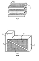
- the figure 1 represents a particular embodiment of an electrode for acid-lead battery according to the invention.
- the electrode comprises a structure 1 provided with a network of pores 1a passing from one main face to the other.
- the pores 1a are perpendicular to the main faces of the grid. They are preferably all identical and separated by thin, weakly porous walls (porosity: 5-10%).
- the cross-section of each pore 1 can be of any type: circular, hexagonal, square, rectangular ...
- a lead-based paste intended to form the active material associated with said electrode fills the pores 1a of the structure 1.
- the network thus formed is preferably a regular network, for example in the form of a honeycomb.
- the lateral faces of the structure 1 are, moreover, covered with an outer armature 2, which is advantageously solid, that is to say compact and the least porous possible.
- the outer armature 2 surrounding the structure 1 comprises, in particular on the figure 1 , a connection element 3, formed for example by a projecting element.
- the structure 1 and the outer frame 2 are based on carbon, preferably glassy.
- Such an electrode has the advantage of being light and strong.
- Another advantage of the porous structure of the electrode according to the invention is the remarkable active surface of the current collector. The ratio of the mass of active material on the surface of the collector is greatly reduced with this grid, which means that the life of these electrodes is important.
- an electrode according to the invention is especially easy to achieve.
- the electrode can be made by means of a manufacturing method that is easy to implement, using a temporary support.
- Tubes for example made of paper, are impregnated with at least one thermosetting resin based on carbon, and then arranged to form a temporary impregnated support 4, as illustrated on FIG. figure 2 .
- the temporary support 4 comprises a network of pores 1a corresponding to the spaces delimited by the walls of the paper tubes. So, on the figure 2 , the temporary support is constituted by an assembly of rectangular section, formed by 70 tubes of square section all identical.
- the resin used to impregnate the temporary support 4 is a thermosetting resin based on carbon. It is therefore able to be carbonized, that is to say to be converted into carbon by a suitable heat treatment.
- the resin is preferably an epoxy resin or a phenol-formaldehyde resin.
- the tubes used may have a diameter or a side of 1 to 4 mm and a wall with a thickness of the order of 0.1 mm.
- the temporary support 4 is then placed in a mold to form the outer reinforcement 2 using a mixture comprising at least one thermosetting resin based on carbon.
- the mixture further comprises carbon and a solvent.
- the input-output of the pores 1a are advantageously closed in order to prevent the entry of the mixture used to form the outer armature 2 into the pores.
- the closure is achieved, for example, by gluing a plate to the ends of the pores.
- the resin of the mixture is preferably the same as that used to impregnate the temporary support 4, which greatly simplifies the manufacturing process.
- the carbon of the mixture may, for example, be in the form of fibers.
- the concentration of the carbon fibers then varies, preferably, from 1 to 10% by weight relative to the weight of resin used and that of the solvent then varies from 5 to 15% by weight relative to the weight of resin used.
- Carbon fibers can also be replaced by particles. These additives allow rapid subsequent carbonization without creating defects in the outer framework.
- the resins are then cured either by the presence of a curing agent, or by heating at 60 ° C, or by the two combined actions.
- the support 4 covered with its reinforcement is then taken out of the mold, then it is sliced to the desired thickness to form grids 5 ( Fig. 3 ). The cutting is, for example, performed using a band saw or similar equipment.
- the grids 5 thus formed undergo a heat treatment, in an inert atmosphere, at a temperature allowing the carbonization of the materials.
- the thermosetting resin based on carbon of the structure 1 and that of the mixture used for the reinforcement 2 are converted into carbon, conductive, having excellent chemical and mechanical resistance.
- the temperature is advantageously of the order of 1000 to 1100 ° C and the carbon obtained is, in particular, vitreous carbon.
- a deposit of lead or a lead-based alloy must cover all the grids 5.
- the layer deposited on each grid 5 is preferably made of pure lead or tin-lead alloy (mass of tin: 1.5 to 2% of the total mass), depending on the type of electrode desired (positive or negative).
- a positive electrode is covered with a deposit of lead and tin 100 to 200 ⁇ m thick and a negative electrode is covered with a pure lead deposit of 20 to 40 .mu.m thick.
- the deposit ensures a good adhesion of the active material, as well as a protection of the carbon surface against oxidation.
- the deposition is preferably carried out by electrodeposition, which allows deposition on large areas and non-porous deposits.
- a step of pasting (or "pasting" in English) is performed, allowing the filling of the pores 1a of the grid 5 by an active material adapted to the desired type of electrode (positive or negative).
- the dough comprises at least one mixture of lead or lead oxide, sulfuric acid and water.
- the thickness of the lead-based paste is 100 to 300 ⁇ m.
- the pores being ordered and homogeneous, the distribution of the active material in the pores is also homogeneous.
- the structure 1, ordinate allows the use of standard equipment to achieve the step of flattening.
- the paste easily fills the pores 1a of a size (diameter or side) of 1 to 4mm and the structure 1 offers excellent retention dough.
- the duty ratio of the active material is 70 to 80%.
- the structure 1 is preferably divided into elementary structures, 1b and 1c on the figure 4 , smaller and separated by an internal frame 6 based on carbon.
- This embodiment is advantageous in the case of large electrodes where the ohmic resistance in the center of the structure 1 can limit the performance of the cell and the slicing can cause physical defects in the structure.
- the temporary support 4 is then preferably divided into several blocks. Spaces are left in the mold between the blocks, which are then filled with the same mixture as that used to make the outer armature 2, to form the inner armature 6.
- FIG 5 illustrates an assembly of an electrode 8 according to the invention (for example that of the figure 1 ) with two type AGM separators 7a and 7b. The latter come to exert compression on the electrode 8.
- the walls of the pores and those of the separators 7a and 7b confine the active material and prevent volume changes thereof. In this way, the interface between the carbon structure and the active material remains intact and the active material retains its entirety.
Landscapes
- Chemical & Material Sciences (AREA)
- Engineering & Computer Science (AREA)
- Chemical Kinetics & Catalysis (AREA)
- General Chemical & Material Sciences (AREA)
- Electrochemistry (AREA)
- Manufacturing & Machinery (AREA)
- Materials Engineering (AREA)
- Ceramic Engineering (AREA)
- Organic Chemistry (AREA)
- Structural Engineering (AREA)
- Composite Materials (AREA)
- Inorganic Chemistry (AREA)
- Dispersion Chemistry (AREA)
- Battery Electrode And Active Subsutance (AREA)
- Cell Electrode Carriers And Collectors (AREA)
Description
- L'invention concerne une électrode de batterie acide-plomb comportant au moins une structure poreuse à base de carbone avec des faces principales parallèles et des faces latérales entourées par une armature externe, la structure poreuse, recouverte d'une couche en plomb ou en alliage à base de plomb, étant remplie d'une pâte à base de plomb.
- L'invention concerne également un procédé de fabrication d'une telle électrode.
- Les batteries acide-plomb sont généralement constituées d'un empilement de cellules électrochimiques. Chaque cellule comporte deux électrodes comprenant chacune un collecteur de courant poreux, également appelé grille, et un matériau actif à base de plomb ou de dioxyde de plomb, ainsi qu'un électrolyte à base d'acide sulfurique.
- Le principal problème des batteries acide-plomb est leur faible densité d'énergie. Dans le cas des batteries acide-plomb à valve (« Valve Regulated Lead-Acid Batteries » ou VRLAB), la densité d'énergie est de 30 à 40 Wh/kg, alors que la valeur théorique de ce type de batterie est de 167 Wh/kg. Deux raisons expliquent la différence entre la valeur théorique et la valeur réelle de la densité d'énergie. Premièrement, les collecteurs de courant de la batterie, qui servent également de supports mécaniques aux matériaux actifs (pâte à base de plomb poreux et pâte à base d'oxyde de plomb poreux) sont en général en plomb (métallique), ce qui augmente considérablement le poids d'une telle batterie. Deuxièmement, le coefficient d'utilisation d'un matériau actif, qui représente la part du matériau actif qui réagit électrochimiquement, est faible. Il varie entre 40 à 50% selon le type de matériau employé pour le collecteur de courant positif ou le collecteur de courant négatif et selon la géométrie employée (collecteurs sous forme de plaques, tubulaires, plans ou bipolaires). Deux phénomènes limitent en général l'efficacité des matériaux actifs :
- pendant la décharge de la batterie, une part du matériau actif subit un phénomène de sulfatation, ce qui augmente de manière significative la résistance ohmique du matériau actif employé et diminue l'utilisation du matériau non sulfaté. Une étude de ce phénomène est par exemple reportée dans l'article « The use of titanium in the lead-acid batteries » (Power Sources 4, ed. D.H. Collins, 1973, pp. 525-538) de Faber pour un collecteur de courant en titane et du dioxyde de plomb utilisé comme matériau actif positif.
- la décharge consomme l'électrolyte. L'électrolyte entre dans l'espace situé entre les deux électrodes de la cellule et s'infiltre dans les pores des collecteurs de courant. Ainsi, les parties du matériau actif situées loin de la surface des collecteurs de courant ne reçoivent pas d'électrolyte et ne participent pas aux réactions, comme cela est décrit par Bode, dans l'article « Lead-Acid Batteries » (John Wiley & Sons, 1977, pp.156-159).
- La comparaison de ces deux phénomènes limitant l'utilisation du matériau actif indique donc que la géométrie des collecteurs de courant, en général sous forme d'une grille, est le principal facteur limitant les performances de la batterie.
- Le brevet
US7060391 propose de remplacer les collecteurs de courant traditionnels en plomb par des collecteurs en carbone très poreux, afin d'améliorer la densité d'énergie de la batterie. Ces collecteurs sont constitués de mousses en carbone telles que les carbones vitreux réticulés également appelés « RVC » ( « Reticulated Vitreous Carbon » ). Les pores de ces mousses sont remplis de matériaux actifs permettant les réactions chimiques. La taille des pores étant inférieure à 1mm, ceci permet d'obtenir un coefficient d'utilisation allant jusqu'à 70% à 80%. Malgré cet avantage, l'utilisation de ces mousses reste limitée en raison des problèmes suivants : - la grande porosité de ces mousses (95% de vide) augmente grandement la résistante électrique. Les solutions qui ajoutent une armature et un connecteur en plomb autour de la mousse pour collecter le courant augmentent le poids de l'électrode et diminuent ainsi la densité d'énergie de la batterie. De plus, ces procédés sont couteux car ils requièrent des équipements spécifiques.
- la structure irrégulière de la mousse rend difficile l'étape d'étalement de la pâte de matériau actif. Une pâte disposée de manière inhomogène dans les pores de la mousse réduit l'utilisation du matériau actif et l'espérance de vie de la batterie.
- De plus, pendant un cycle de charge-décharge, et spécialement lors d'un cycle de décharge profonde, le volume des électrodes varie grandement en raison de la différence des volumes molaires du sulfate de plomb et du plomb/dioxyde de plomb. Les contraintes mécaniques engendrées causent la dégradation progressive de la batterie, en particulier du matériau actif de l'électrode positive. En effet, celui-ci se désagrège et se détache de la grille. Ce problème est résolu en utilisant des séparateurs en fibres de verre microporeux également connus sous le sigle AGM ( « Absorptive Glass Mat » ). Une feuille de type AGM est solidement maintenue entre les deux électrodes exerçant une force de compression sur celles-ci. Cette compression empêche la dégradation du matériau actif causée par le changement de volume et augmente la durée de vie de la batterie, comme cela a été démontré par Takahashi et al. ( « Physical Changes in Positive Active Mass during Deep Discharge-Charge Cycles of Lead-Acid Cell » , J. Electrochem. Soc., Vol. 130, pp. 2144-2149, 1983). Cependant, cette technologie n'est pas applicable aux collecteurs de courant en mousses de carbone, telles que les RVC ou carbone/graphite, puisque la compression provoquerait une cassure du matériau. Or, en l'absence de séparateurs de type AGM, les mousses de carbone ont une durée de vie courte.
- L'invention a pour but une électrode pour batterie acide-plomb comportant au moins une structure poreuse à base de carbone avec des faces principales parallèles et des faces latérales entourées par une armature externe et la structure poreuse, recouverte d'une couche en plomb ou en alliage à base de plomb, étant remplie d'une pâte à base de plomb, et remédiant aux inconvénients de l'art antérieur. Plus particulièrement, l'invention a pour but une électrode compacte, légère, solide et facile à réaliser, permettant la fabrication de batteries de forte densité énergétique.
- Selon l'invention, ce but est atteint par le fait que la structure comporte un réseau ordonné de pores traversants, homogènes et perpendiculaires audites faces principales et par le fait que l'armature externe est à base de carbone et recouverte d'une couche en plomb ou en alliage à base de plomb.
- L'invention a également pour but un procédé de fabrication d'une telle électrode, facile à mettre en oeuvre.
- Ce but est atteint par le fait que le procédé comporte successivement :
- la réalisation d'un support provisoire comportant ledit réseau ordonné de pores, imprégné d'au moins une première résine thermodurcissable à base de carbone,
- la formation de l'armature externe autour dudit support provisoire, par moulage à l'aide d'un mélange comprenant au moins une seconde résine thermodurcissable à base de carbone, et durcissement dudit mélange,
- le découpage en tranches de l'ensemble formé par le support provisoire entouré de l'armature externe,
- le traitement thermique en atmosphère inerte dudit ensemble, carbonisant les matériaux de l'ensemble,
- le dépôt d'une couche en plomb ou en alliage à base de plomb sur toutes les surfaces de l'ensemble,
- le remplissage à l'aide d'une pâte à base de plomb constituant le matériau actif de la batterie, des pores de la structure poreuse obtenue après le traitement thermique.
- D'autres avantages et caractéristiques ressortiront plus clairement de la description qui va suivre de modes particuliers de réalisation de l'invention donnés à titre d'exemples non limitatifs et représentés aux dessins annexés, dans lesquels :
- la
figure 1 représente un mode particulier de réalisation d'une électrode de batterie acide-plomb selon l'invention. - les
figures 2 et3 représentent différentes étapes d'un procédé de fabrication d'électrodes selon lafigure 1 . - la
figure 4 représente une variante de réalisation d'une électrode selon l'invention. - la
figure 5 représente un empilement de séparateurs de type AGM et d'une électrode selon l'invention - La
figure 1 représente un mode particulier de réalisation d'une électrode pour batterie acide-plomb selon l'invention. L'électrode comporte une structure 1 munie d'un réseau de pores 1a traversant d'une face principale à l'autre. Les pores 1a sont perpendiculaires aux faces principales de la grille. Ils sont, de préférence, tous identiques et séparés par des parois fines, faiblement poreuses (porosité : 5-10%). La section transversale de chaque pore 1 a peut être de tout type : circulaire, hexagonal, carré, rectangulaire... De plus, une pâte à base de plomb destinée à former le matériau actif associé à ladite électrode remplit les pores 1 a de la structure 1. Le réseau ainsi formé est, de préférence, un réseau régulier, par exemple sous forme de nid d'abeille. - Les faces latérales de la structure 1 sont, de plus, recouvertes d'une armature externe 2, qui est avantageusement massive c'est-à-dire compacte et la moins poreuse possible. L'armature externe 2 entourant la structure 1 comporte, en particulier sur la
figure 1 , un élément de connexion 3, formé par exemple par un élément en saillie. La structure 1 et l'armature externe 2 sont à base de carbone, de préférence, vitreux. Une telle électrode présente l'avantage d'être légère et solide. Un autre avantage de la structure poreuse de l'électrode selon l'invention est la remarquable surface active du collecteur de courant. Le rapport de la masse de matériau actif sur la surface du collecteur est grandement diminué avec cette grille, ce qui signifie que la durée de vie de ces électrodes est importante. Enfin, une électrode selon l'invention est surtout facile à réaliser. - Ainsi, l'électrode peut être réalisée au moyen d'un procédé de fabrication facile à mettre en oeuvre, utilisant un support provisoire. Des tubes, par exemple en papier, sont imprégnés d'au moins une résine thermodurcissable à base de carbone, puis arrangés pour former un support provisoire 4 imprégné, tel qu'illustré sur la
figure 2 . Le support provisoire 4 comporte un réseau de pores 1 a correspondant aux espaces délimités par les parois des tubes en papier. Ainsi, sur lafigure 2 , le support provisoire est constitué par un assemblage de section rectangulaire, formé par 70 tubes de section carrée tous identiques. - Par ailleurs, la résine utilisée pour imprégner le support provisoire 4 est une résine thermodurcissable à base de carbone. Elle est donc apte à être carbonisée, c'est-à-dire à être transformée en carbone par un traitement thermique adapté. La résine est, de préférence, une résine epoxy ou une résine à base de phénol-formaldéhyde. Avantageusement, il est possible d'utiliser des supports en papier imprégnés de résine disponibles dans le commerce. Ces supports sont peu chers. Avantageusement, les tubes employés peuvent avoir un diamètre ou un côté de 1 à 4mm et une paroi d'une épaisseur de l'ordre de 0,1 mm.
- Le support provisoire 4 est ensuite placé dans un moule pour former l'armature externe 2 en utilisant un mélange comportant au moins une résine thermodurcissable à base de carbone. Avantageusement, le mélange comporte, de plus, du carbone et un solvant. Au préalable, les entrées-sorties des pores 1a sont avantageusement fermées afin d'empêcher l'entrée du mélange utilisé pour former l'armature externe 2, dans les pores. La fermeture est réalisée, par exemple, en collant une plaque aux extrémités des pores. La résine du mélange est, de préférence, la même que celle utilisée pour imprégner le support provisoire 4, ce qui simplifie grandement le procédé de fabrication. Le carbone du mélange peut, par exemple, être sous forme de fibres. La concentration des fibres de carbone varie alors, de préférence, de 1 à 10% en poids par rapport au poids de résine utilisée et celle du solvant varie alors de 5 à 15% en poids par rapport au poids de résine utilisée. Les fibres de carbone peuvent également être remplacées par des particules. Ces additifs permettent une carbonisation ultérieure rapide sans créer de défauts dans l'armature externe. Les résines sont ensuite durcies soit par la présence d'un agent durcisseur, soit par chauffage à 60°C, soit par les deux actions conjuguées. Le support 4 recouvert de son armature est ensuite sorti du moule, puis il est découpé en tranches à l'épaisseur désirée pour former des grilles 5 (
fig. 3 ). La découpe est, par exemple, réalisée à l'aide d'une scie à bande ou tout équipement similaire. - Puis, les grilles 5 ainsi formées subissent un traitement thermique, dans une atmosphère inerte, à une température permettant la carbonisation des matériaux. Durant cette étape, la résine thermodurcissable à base de carbone de la structure 1 et celle du mélange utilisé pour l'armature 2 sont transformées en carbone, conducteur, ayant une excellente résistance chimique et mécanique. La température est avantageusement de l'ordre de 1000 à 1100°C et le carbone obtenu est, en particulier, du carbone vitreux.
- Un dépôt de plomb ou d'un alliage à base de plomb doit recouvrir l'ensemble des grilles 5. La couche déposée sur chaque grille 5 est, de préférence, en plomb pur ou en alliage à base d'étain et de plomb (masse d'étain : 1,5 à 2% de la masse totale), selon le type d'électrode souhaité (positif ou négatif). De préférence, une électrode positive est recouverte d'un dépôt de plomb et d'étain de 100 à 200µm d'épaisseur et une électrode négative est recouverte d'un dépôt de plomb pur de 20 à 40µm d'épaisseur. Le dépôt assure une bonne adhésion du matériau actif, ainsi qu'une protection de la surface de carbone contre l'oxydation. Le dépôt est réalisé, de préférence, par électrodéposition, ce qui permet le dépôt sur de grandes surfaces et des dépôts non poreux. Puis, une étape d'empattage (ou « pasting » en anglais) est réalisée, permettant le remplissage des pores 1a de la grille 5 par un matériau actif adapté selon le type d'électrode souhaité (positif ou négatif). La pâte comporte au moins un mélange de plomb ou d'oxyde de plomb, d'acide sulfurique et d'eau. De préférence, l'épaisseur de la pâte à base de plomb est de 100 à 300µm. Les pores étant ordonnés et homogènes, la distribution du matériau actif dans les pores est également homogène. La structure 1, ordonnée, permet l'utilisation d'équipements usuels pour réaliser l'étape d'empattage. La pâte remplit aisément les pores 1a d'une taille (diamètre ou côté) de 1 à 4mm et la structure 1 offre une excellente rétention de la pâte. Avec une dimension de pores de 1 à 4mm et une épaisseur des parois de 0,1 à 0,5mm comprenant l'épaisseur du revêtement de l'alliage, le coefficient d'utilisation du matériau actif est de 70 à 80%.
- La réalisation d'une structure poreuse en carbone à l'aide d'un support provisoire en papier imprégné de résine a déjà été décrite dans le brevet
US3825460 . Cependant, la structure en carbone décrite dans le brevetUS3825460 ne serait pas utilisable directement en tant qu'électrode pour une batterie acide-plomb. En effet, la capacité de transport du courant sur le périmètre de cette structure n'est pas suffisante pour collecter tout le courant généré dans la structure. De plus, du fait du réseau ordonné de pores, la structure possède des propriétés mécaniques anisotropes. En effet, la structure est résistante aux forces de compression dans une direction parallèle aux pores traversants mais ne résisterait pas à un effort de flexion. Ainsi, une telle structure est selon l'invention consolidée par une armature externe, formée autour de ses faces latérales extérieures. Par ailleurs, cette armature présente l'avantage d'être en carbone, allégeant ainsi l'électrode, et d'être facile à réaliser. L'armature externe 2 a, de préférence, une section carrée de 2x2mm à 4x4mm, ce qui est suffisant pour assurer à la fois la résistance mécanique et une collecte efficace du courant. - Dans le mode de réalisation particulier représenté sur la
figure 4 , la structure 1 est, de préférence, divisée en structures élémentaires, 1b et 1c sur lafigure 4 , plus petites et séparées par une armature interne 6 à base de carbone. Ce mode de réalisation est avantageux dans le cas d'électrodes de grandes dimensions où la résistance ohmique au centre de la structure 1 peut limiter les performances de la cellule et le découpage en tranches peut occasionner des défauts physiques dans la structure. Dans de tels cas, le support provisoire 4 est alors, de préférence, divisé en plusieurs blocs. Des espaces sont laissés dans le moule entre les blocs, qui sont ensuite remplis par le même mélange que celui utilisé pour réaliser l'armature externe 2, afin de former l'armature interne 6. - Une électrode selon l'invention décrite précédemment permet l'assemblage de cellules acide-plomb à valve (VRLA) et contrairement à l'art antérieur, de batteries avec des séparateurs de type AGM. La
figure 5 illustre un assemblage d'une électrode 8 selon l'invention (par exemple celle de lafigure 1 ) avec deux séparateurs de type AGM 7a et 7b. Ces derniers viennent exercer une compression sur l'électrode 8. Les parois des pores et celles des séparateurs 7a et 7b confinent le matériau actif et empêchent les changements de volume de celui-ci. De cette manière, l'interface entre la structure en carbone et le matériau actif reste intacte et le matériau actif conserve son intégralité.
Claims (11)
- Electrode (8) de batterie acide-plomb comportant au moins une structure poreuse (1) à base de carbone avec des faces principales parallèles et des faces latérales entourées par une armature externe (2), la structure poreuse (1), recouverte d'une couche en plomb ou en alliage à base de plomb, étant remplie d'une pâte à base de plomb, électrode (8) caractérisée en ce que :- la structure poreuse (1) comporte un réseau ordonné de pores (1a) traversants, homogènes et perpendiculaires auxdites faces principales- et l'armature externe (2) est à base de carbone et recouverte d'une couche en plomb ou en alliage à base de plomb.
- Electrode (8) selon la revendication 1, caractérisée en ce que l'armature externe (2) est en carbone vitreux.
- Electrode (8) selon l'une des revendications 1 et 2, caractérisée en ce que la structure poreuse (1) est en carbone vitreux.
- Electrode (8) selon l'une quelconque des revendications 1 à 3, caractérisée en ce que le réseau de pores est sous forme de nid d'abeille.
- Electrode (8) selon l'une quelconque des revendications 1 à 4, caractérisée en ce que les pores ont une taille de 1 à 4mm.
- Electrode (8) selon l'une quelconque des revendications 1 à 5, caractérisée en ce que la structure est divisée en au moins deux parties (1 b, 1 c) par une armature interne (6), à base de carbone.
- Procédé de fabrication d'une électrode (8) selon l'une quelconque des revendications 1 à 6, caractérisé en ce qu'il comporte successivement :- la réalisation d'un support provisoire (4) comportant ledit réseau ordonné de pores (1 a), imprégné d'au moins une première résine thermodurcissable à base de carbone,- la formation de l'armature externe (2) autour dudit support provisoire (4), par moulage à l'aide d'un mélange comprenant au moins une seconde résine thermodurcissable à base de carbone, et durcissement dudit mélange,- le découpage en tranches de l'ensemble formé par le support provisoire (4) entouré de l'armature externe (2),- le traitement thermique en atmosphère inerte dudit ensemble, carbonisant les matériaux de l'ensemble,- le dépôt d'une couche en plomb ou en alliage à base de plomb sur toutes les surfaces de l'ensemble,- le remplissage à l'aide d'une pâte à base de plomb constituant le matériau actif de la batterie, des pores (1a) de la structure poreuse (1 ; 1 b, 1 c) obtenue après le traitement thermique.
- Procédé selon la revendication 7, caractérisé en ce que le support provisoire (4) est en papier.
- Procédé selon l'une quelconque des revendications 7 et 8, caractérisé en ce que les première et seconde résines thermodurcissables à base de carbone sont identiques.
- Procédé selon l'une quelconque des revendications 7 à 9, caractérisé en ce que le mélange comprend des fibres ou des particules de carbone, et un solvant.
- Procédé selon l'une quelconque des revendications 7 à 10, caractérisé en ce que le dépôt de la couche en plomb ou en alliage à base de plomb est réalisé par électrodéposition.
Applications Claiming Priority (2)
| Application Number | Priority Date | Filing Date | Title |
|---|---|---|---|
| FR0901666A FR2944151B1 (fr) | 2009-04-06 | 2009-04-06 | Electrode de batterie acide-plomb comportant un reseau de pores traversants et procede de fabrication |
| PCT/EP2010/053771 WO2010115705A1 (fr) | 2009-04-06 | 2010-03-23 | Electrode de batterie acide-plomb comportant un reseau de pores traversants et procede de fabrication |
Publications (2)
| Publication Number | Publication Date |
|---|---|
| EP2417654A1 EP2417654A1 (fr) | 2012-02-15 |
| EP2417654B1 true EP2417654B1 (fr) | 2013-09-18 |
Family
ID=40940393
Family Applications (1)
| Application Number | Title | Priority Date | Filing Date |
|---|---|---|---|
| EP10709748.7A Not-in-force EP2417654B1 (fr) | 2009-04-06 | 2010-03-23 | Electrode de batterie acide-plomb comportant un reseau de pores traversants et procede de fabrication |
Country Status (8)
| Country | Link |
|---|---|
| US (1) | US8173300B2 (fr) |
| EP (1) | EP2417654B1 (fr) |
| JP (1) | JP5628286B2 (fr) |
| CN (1) | CN102460780B (fr) |
| BR (1) | BRPI1014476A2 (fr) |
| ES (1) | ES2439017T3 (fr) |
| FR (1) | FR2944151B1 (fr) |
| WO (1) | WO2010115705A1 (fr) |
Families Citing this family (11)
| Publication number | Priority date | Publication date | Assignee | Title |
|---|---|---|---|---|
| US8765297B2 (en) | 2011-01-04 | 2014-07-01 | Exide Technologies | Advanced graphite additive for enhanced cycle-life of lead-acid batteries |
| US8808914B2 (en) | 2012-01-13 | 2014-08-19 | Energy Power Systems, LLC | Lead-acid battery design having versatile form factor |
| US9263721B2 (en) | 2012-01-13 | 2016-02-16 | Energy Power Systems LLC | Lead-acid battery design having versatile form factor |
| US9595360B2 (en) | 2012-01-13 | 2017-03-14 | Energy Power Systems LLC | Metallic alloys having amorphous, nano-crystalline, or microcrystalline structure |
| US10014520B2 (en) | 2012-10-31 | 2018-07-03 | Exide Technologies Gmbh | Composition that enhances deep cycle performance of valve-regulated lead-acid batteries filled with gel electrolyte |
| WO2015103285A1 (fr) * | 2013-12-30 | 2015-07-09 | Gridtential Energy, Inc. | Matériaux actifs architecturaux pour batteries d'accumulateurs au plomb |
| WO2015181508A1 (fr) * | 2014-05-30 | 2015-12-03 | Commissariat A L'energie Atomique Et Aux Energies Alternatives | Accumulateur au plomb-acide et procédé de fabrication d'un tel accumulateur |
| CN106486645A (zh) * | 2015-08-24 | 2017-03-08 | 中国科学院金属研究所 | 一种含有网络状碳材料的铅炭电池负极板及其制备方法 |
| USD809869S1 (en) | 2016-02-05 | 2018-02-13 | Yeti Coolers, Llc | Insulating device |
| USD799277S1 (en) | 2016-02-05 | 2017-10-10 | Yeti Coolers, Llc | Insulating device |
| USD798670S1 (en) | 2016-02-05 | 2017-10-03 | Yeti Coolers, Llc | Insulating device |
Family Cites Families (11)
| Publication number | Priority date | Publication date | Assignee | Title |
|---|---|---|---|---|
| JPS558325B1 (fr) * | 1971-05-18 | 1980-03-03 | ||
| US3825406A (en) | 1972-08-24 | 1974-07-23 | Infra Ray Division Solaronics | Radiation-convection heating system |
| US5451444A (en) | 1993-01-29 | 1995-09-19 | Deliso; Evelyn M. | Carbon-coated inorganic substrates |
| JPH10188996A (ja) * | 1996-12-26 | 1998-07-21 | Matsushita Electric Ind Co Ltd | 鉛蓄電池用格子体 |
| US6214204B1 (en) | 1999-08-27 | 2001-04-10 | Corning Incorporated | Ion-removal from water using activated carbon electrodes |
| CA2499733A1 (fr) | 2001-09-26 | 2003-04-03 | Elod Gyenge | Structure de collecteur de courant et procedes pour ameliorer les performances d'un accumulateur au plomb |
| US6979513B2 (en) * | 2002-06-28 | 2005-12-27 | Firefly Energy Inc. | Battery including carbon foam current collectors |
| US20050084737A1 (en) | 2003-10-20 | 2005-04-21 | Wine David W. | Fuel cells having cross directional laminar flowstreams |
| US20060292448A1 (en) * | 2005-02-02 | 2006-12-28 | Elod Gyenge | Current Collector Structure and Methods to Improve the Performance of a Lead-Acid Battery |
| WO2006092060A1 (fr) * | 2005-03-04 | 2006-09-08 | Vizon Scitec Inc. | Procédé pour améliorer la performance d'un accumulateur au plomb |
| US20090053601A1 (en) * | 2005-03-31 | 2009-02-26 | Kelley Kurtis C | Modular Bipolar Battery |
-
2009
- 2009-04-06 FR FR0901666A patent/FR2944151B1/fr not_active Expired - Fee Related
-
2010
- 2010-03-23 JP JP2012503949A patent/JP5628286B2/ja not_active Expired - Fee Related
- 2010-03-23 ES ES10709748.7T patent/ES2439017T3/es active Active
- 2010-03-23 BR BRPI1014476A patent/BRPI1014476A2/pt not_active IP Right Cessation
- 2010-03-23 US US13/256,322 patent/US8173300B2/en not_active Expired - Fee Related
- 2010-03-23 WO PCT/EP2010/053771 patent/WO2010115705A1/fr not_active Ceased
- 2010-03-23 EP EP10709748.7A patent/EP2417654B1/fr not_active Not-in-force
- 2010-03-23 CN CN201080024952.7A patent/CN102460780B/zh not_active Expired - Fee Related
Also Published As
| Publication number | Publication date |
|---|---|
| US8173300B2 (en) | 2012-05-08 |
| BRPI1014476A2 (pt) | 2016-04-05 |
| CN102460780A (zh) | 2012-05-16 |
| JP5628286B2 (ja) | 2014-11-19 |
| FR2944151B1 (fr) | 2011-04-01 |
| CN102460780B (zh) | 2014-07-02 |
| EP2417654A1 (fr) | 2012-02-15 |
| WO2010115705A1 (fr) | 2010-10-14 |
| ES2439017T3 (es) | 2014-01-21 |
| FR2944151A1 (fr) | 2010-10-08 |
| JP2012523097A (ja) | 2012-09-27 |
| US20120003543A1 (en) | 2012-01-05 |
Similar Documents
| Publication | Publication Date | Title |
|---|---|---|
| WO2010115705A1 (fr) | Electrode de batterie acide-plomb comportant un reseau de pores traversants et procede de fabrication | |
| EP2417661B1 (fr) | Cellule electrochimique a flux d'electrolyte comportant des electrodes traversantes et procede de fabrication | |
| EP3624241B1 (fr) | Procédé de fabrication d'un guide d'écoulement de réacteur électrochimique | |
| EP3149790A1 (fr) | Accumulateur au plomb-acide et procédé de fabrication d'un tel accumulateur | |
| US20110083966A1 (en) | Electrode for lead-acid battery and method for producing such an electrode | |
| FR3121553A1 (fr) | Fabrication d'anodes par lamination de motifs, anodes fabriquées ainsi, et dispositifs électrochimiques incorporant de telles anodes | |
| CN110854358A (zh) | 硫化物全固体电池用负极和硫化物全固体电池 | |
| CN116779947A (zh) | 锂离子电池及其制备方法 | |
| WO2015092267A1 (fr) | Compartiment anodique avec collecteur en alliage amorphe | |
| FR3023980A1 (fr) | Batterie filaire et procede de realisation d'une batterie filaire | |
| US20150056505A1 (en) | Manganese and iron electrode cell | |
| JPH0268855A (ja) | 電池用電極の製造方法 | |
| KR102900627B1 (ko) | 일방향으로 두께가 감소하는 단위 셀이 방사형으로 집합된 구조를 포함하는 이차전지 및 이를 포함하는 디바이스. | |
| CN107230776B (zh) | 铅碳接合的制作方法、铅碳电极片的结构以及铅碳电池的结构 | |
| CN114628676B (zh) | 蜂窝型锂离子电池和其制造方法 | |
| CN115719795A (zh) | 一种二次电池 | |
| FR2677812A1 (fr) | Accumulateur alcalin a electrodes bipolaires et procedes de fabrication. | |
| WO2020178509A1 (fr) | Électrode pour dispositif de stockage de l'énergie rechargeable | |
| CN118738531B (zh) | 固态电池簇和电池模组 | |
| FR3021812A1 (fr) | Accumulateur au plomb-acide, procede de fabrication d'un tel accumulateur et procede de fabrication d'une electrode | |
| FR3021810A1 (fr) | Accumulateur au plomb-acide, procede de fabrication d'un tel accumulateur et procede de fabrication d'une electrode | |
| FR2544134A1 (fr) | Procede de fabrication d'une electrode pour generateur electrochimique, electrode ainsi obtenue et applications | |
| FR2682536A1 (fr) | Electrodes bipolaires pour accumulateur au plomb. | |
| CN120784256A (zh) | 一种储能电池的制备方法及储能电池 | |
| FR3115162A1 (fr) | Electrode pour cellule de batterie solide et procédé de fabrication d’une cellule de batterie utilisant une telle électrode. |
Legal Events
| Date | Code | Title | Description |
|---|---|---|---|
| PUAI | Public reference made under article 153(3) epc to a published international application that has entered the european phase |
Free format text: ORIGINAL CODE: 0009012 |
|
| 17P | Request for examination filed |
Effective date: 20110928 |
|
| AK | Designated contracting states |
Kind code of ref document: A1 Designated state(s): AT BE BG CH CY CZ DE DK EE ES FI FR GB GR HR HU IE IS IT LI LT LU LV MC MK MT NL NO PL PT RO SE SI SK SM TR |
|
| DAX | Request for extension of the european patent (deleted) | ||
| GRAP | Despatch of communication of intention to grant a patent |
Free format text: ORIGINAL CODE: EPIDOSNIGR1 |
|
| INTG | Intention to grant announced |
Effective date: 20130423 |
|
| GRAS | Grant fee paid |
Free format text: ORIGINAL CODE: EPIDOSNIGR3 |
|
| GRAA | (expected) grant |
Free format text: ORIGINAL CODE: 0009210 |
|
| AK | Designated contracting states |
Kind code of ref document: B1 Designated state(s): AT BE BG CH CY CZ DE DK EE ES FI FR GB GR HR HU IE IS IT LI LT LU LV MC MK MT NL NO PL PT RO SE SI SK SM TR |
|
| REG | Reference to a national code |
Ref country code: GB Ref legal event code: FG4D Free format text: NOT ENGLISH |
|
| REG | Reference to a national code |
Ref country code: CH Ref legal event code: EP |
|
| REG | Reference to a national code |
Ref country code: IE Ref legal event code: FG4D Free format text: LANGUAGE OF EP DOCUMENT: FRENCH |
|
| REG | Reference to a national code |
Ref country code: AT Ref legal event code: REF Ref document number: 633189 Country of ref document: AT Kind code of ref document: T Effective date: 20131015 |
|
| REG | Reference to a national code |
Ref country code: DE Ref legal event code: R096 Ref document number: 602010010362 Country of ref document: DE Effective date: 20131114 |
|
| REG | Reference to a national code |
Ref country code: ES Ref legal event code: FG2A Ref document number: 2439017 Country of ref document: ES Kind code of ref document: T3 Effective date: 20140121 |
|
| PG25 | Lapsed in a contracting state [announced via postgrant information from national office to epo] |
Ref country code: HR Free format text: LAPSE BECAUSE OF FAILURE TO SUBMIT A TRANSLATION OF THE DESCRIPTION OR TO PAY THE FEE WITHIN THE PRESCRIBED TIME-LIMIT Effective date: 20130918 Ref country code: CY Free format text: LAPSE BECAUSE OF FAILURE TO SUBMIT A TRANSLATION OF THE DESCRIPTION OR TO PAY THE FEE WITHIN THE PRESCRIBED TIME-LIMIT Effective date: 20130814 Ref country code: NO Free format text: LAPSE BECAUSE OF FAILURE TO SUBMIT A TRANSLATION OF THE DESCRIPTION OR TO PAY THE FEE WITHIN THE PRESCRIBED TIME-LIMIT Effective date: 20131218 Ref country code: SE Free format text: LAPSE BECAUSE OF FAILURE TO SUBMIT A TRANSLATION OF THE DESCRIPTION OR TO PAY THE FEE WITHIN THE PRESCRIBED TIME-LIMIT Effective date: 20130918 Ref country code: LT Free format text: LAPSE BECAUSE OF FAILURE TO SUBMIT A TRANSLATION OF THE DESCRIPTION OR TO PAY THE FEE WITHIN THE PRESCRIBED TIME-LIMIT Effective date: 20130918 |
|
| REG | Reference to a national code |
Ref country code: NL Ref legal event code: VDEP Effective date: 20130918 |
|
| REG | Reference to a national code |
Ref country code: AT Ref legal event code: MK05 Ref document number: 633189 Country of ref document: AT Kind code of ref document: T Effective date: 20130918 |
|
| REG | Reference to a national code |
Ref country code: LT Ref legal event code: MG4D |
|
| PG25 | Lapsed in a contracting state [announced via postgrant information from national office to epo] |
Ref country code: GR Free format text: LAPSE BECAUSE OF FAILURE TO SUBMIT A TRANSLATION OF THE DESCRIPTION OR TO PAY THE FEE WITHIN THE PRESCRIBED TIME-LIMIT Effective date: 20131219 Ref country code: LV Free format text: LAPSE BECAUSE OF FAILURE TO SUBMIT A TRANSLATION OF THE DESCRIPTION OR TO PAY THE FEE WITHIN THE PRESCRIBED TIME-LIMIT Effective date: 20130918 Ref country code: SI Free format text: LAPSE BECAUSE OF FAILURE TO SUBMIT A TRANSLATION OF THE DESCRIPTION OR TO PAY THE FEE WITHIN THE PRESCRIBED TIME-LIMIT Effective date: 20130918 Ref country code: FI Free format text: LAPSE BECAUSE OF FAILURE TO SUBMIT A TRANSLATION OF THE DESCRIPTION OR TO PAY THE FEE WITHIN THE PRESCRIBED TIME-LIMIT Effective date: 20130918 |
|
| PG25 | Lapsed in a contracting state [announced via postgrant information from national office to epo] |
Ref country code: CY Free format text: LAPSE BECAUSE OF FAILURE TO SUBMIT A TRANSLATION OF THE DESCRIPTION OR TO PAY THE FEE WITHIN THE PRESCRIBED TIME-LIMIT Effective date: 20130918 |
|
| PG25 | Lapsed in a contracting state [announced via postgrant information from national office to epo] |
Ref country code: EE Free format text: LAPSE BECAUSE OF FAILURE TO SUBMIT A TRANSLATION OF THE DESCRIPTION OR TO PAY THE FEE WITHIN THE PRESCRIBED TIME-LIMIT Effective date: 20130918 Ref country code: NL Free format text: LAPSE BECAUSE OF FAILURE TO SUBMIT A TRANSLATION OF THE DESCRIPTION OR TO PAY THE FEE WITHIN THE PRESCRIBED TIME-LIMIT Effective date: 20130918 Ref country code: SK Free format text: LAPSE BECAUSE OF FAILURE TO SUBMIT A TRANSLATION OF THE DESCRIPTION OR TO PAY THE FEE WITHIN THE PRESCRIBED TIME-LIMIT Effective date: 20130918 Ref country code: CZ Free format text: LAPSE BECAUSE OF FAILURE TO SUBMIT A TRANSLATION OF THE DESCRIPTION OR TO PAY THE FEE WITHIN THE PRESCRIBED TIME-LIMIT Effective date: 20130918 Ref country code: IS Free format text: LAPSE BECAUSE OF FAILURE TO SUBMIT A TRANSLATION OF THE DESCRIPTION OR TO PAY THE FEE WITHIN THE PRESCRIBED TIME-LIMIT Effective date: 20140118 |
|
| PG25 | Lapsed in a contracting state [announced via postgrant information from national office to epo] |
Ref country code: AT Free format text: LAPSE BECAUSE OF FAILURE TO SUBMIT A TRANSLATION OF THE DESCRIPTION OR TO PAY THE FEE WITHIN THE PRESCRIBED TIME-LIMIT Effective date: 20130918 Ref country code: PL Free format text: LAPSE BECAUSE OF FAILURE TO SUBMIT A TRANSLATION OF THE DESCRIPTION OR TO PAY THE FEE WITHIN THE PRESCRIBED TIME-LIMIT Effective date: 20130918 |
|
| REG | Reference to a national code |
Ref country code: DE Ref legal event code: R097 Ref document number: 602010010362 Country of ref document: DE |
|
| PG25 | Lapsed in a contracting state [announced via postgrant information from national office to epo] |
Ref country code: PT Free format text: LAPSE BECAUSE OF FAILURE TO SUBMIT A TRANSLATION OF THE DESCRIPTION OR TO PAY THE FEE WITHIN THE PRESCRIBED TIME-LIMIT Effective date: 20140120 |
|
| PLBE | No opposition filed within time limit |
Free format text: ORIGINAL CODE: 0009261 |
|
| STAA | Information on the status of an ep patent application or granted ep patent |
Free format text: STATUS: NO OPPOSITION FILED WITHIN TIME LIMIT |
|
| 26N | No opposition filed |
Effective date: 20140619 |
|
| PG25 | Lapsed in a contracting state [announced via postgrant information from national office to epo] |
Ref country code: DK Free format text: LAPSE BECAUSE OF FAILURE TO SUBMIT A TRANSLATION OF THE DESCRIPTION OR TO PAY THE FEE WITHIN THE PRESCRIBED TIME-LIMIT Effective date: 20130918 |
|
| REG | Reference to a national code |
Ref country code: DE Ref legal event code: R097 Ref document number: 602010010362 Country of ref document: DE Effective date: 20140619 |
|
| PG25 | Lapsed in a contracting state [announced via postgrant information from national office to epo] |
Ref country code: LU Free format text: LAPSE BECAUSE OF FAILURE TO SUBMIT A TRANSLATION OF THE DESCRIPTION OR TO PAY THE FEE WITHIN THE PRESCRIBED TIME-LIMIT Effective date: 20140323 |
|
| REG | Reference to a national code |
Ref country code: CH Ref legal event code: PL |
|
| REG | Reference to a national code |
Ref country code: IE Ref legal event code: MM4A |
|
| PG25 | Lapsed in a contracting state [announced via postgrant information from national office to epo] |
Ref country code: IE Free format text: LAPSE BECAUSE OF NON-PAYMENT OF DUE FEES Effective date: 20140323 Ref country code: LI Free format text: LAPSE BECAUSE OF NON-PAYMENT OF DUE FEES Effective date: 20140331 Ref country code: CH Free format text: LAPSE BECAUSE OF NON-PAYMENT OF DUE FEES Effective date: 20140331 |
|
| PG25 | Lapsed in a contracting state [announced via postgrant information from national office to epo] |
Ref country code: MT Free format text: LAPSE BECAUSE OF FAILURE TO SUBMIT A TRANSLATION OF THE DESCRIPTION OR TO PAY THE FEE WITHIN THE PRESCRIBED TIME-LIMIT Effective date: 20130918 |
|
| REG | Reference to a national code |
Ref country code: FR Ref legal event code: PLFP Year of fee payment: 7 |
|
| PG25 | Lapsed in a contracting state [announced via postgrant information from national office to epo] |
Ref country code: SM Free format text: LAPSE BECAUSE OF FAILURE TO SUBMIT A TRANSLATION OF THE DESCRIPTION OR TO PAY THE FEE WITHIN THE PRESCRIBED TIME-LIMIT Effective date: 20130918 |
|
| PG25 | Lapsed in a contracting state [announced via postgrant information from national office to epo] |
Ref country code: MC Free format text: LAPSE BECAUSE OF FAILURE TO SUBMIT A TRANSLATION OF THE DESCRIPTION OR TO PAY THE FEE WITHIN THE PRESCRIBED TIME-LIMIT Effective date: 20130918 Ref country code: RO Free format text: LAPSE BECAUSE OF FAILURE TO SUBMIT A TRANSLATION OF THE DESCRIPTION OR TO PAY THE FEE WITHIN THE PRESCRIBED TIME-LIMIT Effective date: 20130918 |
|
| PG25 | Lapsed in a contracting state [announced via postgrant information from national office to epo] |
Ref country code: BG Free format text: LAPSE BECAUSE OF FAILURE TO SUBMIT A TRANSLATION OF THE DESCRIPTION OR TO PAY THE FEE WITHIN THE PRESCRIBED TIME-LIMIT Effective date: 20130918 |
|
| PG25 | Lapsed in a contracting state [announced via postgrant information from national office to epo] |
Ref country code: HU Free format text: LAPSE BECAUSE OF FAILURE TO SUBMIT A TRANSLATION OF THE DESCRIPTION OR TO PAY THE FEE WITHIN THE PRESCRIBED TIME-LIMIT; INVALID AB INITIO Effective date: 20100323 Ref country code: BE Free format text: LAPSE BECAUSE OF FAILURE TO SUBMIT A TRANSLATION OF THE DESCRIPTION OR TO PAY THE FEE WITHIN THE PRESCRIBED TIME-LIMIT Effective date: 20140331 Ref country code: TR Free format text: LAPSE BECAUSE OF FAILURE TO SUBMIT A TRANSLATION OF THE DESCRIPTION OR TO PAY THE FEE WITHIN THE PRESCRIBED TIME-LIMIT Effective date: 20130918 |
|
| REG | Reference to a national code |
Ref country code: FR Ref legal event code: PLFP Year of fee payment: 8 |
|
| PGFP | Annual fee paid to national office [announced via postgrant information from national office to epo] |
Ref country code: IT Payment date: 20170317 Year of fee payment: 8 |
|
| PGFP | Annual fee paid to national office [announced via postgrant information from national office to epo] |
Ref country code: ES Payment date: 20170331 Year of fee payment: 8 |
|
| REG | Reference to a national code |
Ref country code: FR Ref legal event code: PLFP Year of fee payment: 9 |
|
| PG25 | Lapsed in a contracting state [announced via postgrant information from national office to epo] |
Ref country code: MK Free format text: LAPSE BECAUSE OF FAILURE TO SUBMIT A TRANSLATION OF THE DESCRIPTION OR TO PAY THE FEE WITHIN THE PRESCRIBED TIME-LIMIT Effective date: 20130918 |
|
| PG25 | Lapsed in a contracting state [announced via postgrant information from national office to epo] |
Ref country code: IT Free format text: LAPSE BECAUSE OF NON-PAYMENT OF DUE FEES Effective date: 20180323 |
|
| PGFP | Annual fee paid to national office [announced via postgrant information from national office to epo] |
Ref country code: GB Payment date: 20190320 Year of fee payment: 10 Ref country code: DE Payment date: 20190312 Year of fee payment: 10 Ref country code: FR Payment date: 20190329 Year of fee payment: 10 |
|
| REG | Reference to a national code |
Ref country code: ES Ref legal event code: FD2A Effective date: 20190911 |
|
| PG25 | Lapsed in a contracting state [announced via postgrant information from national office to epo] |
Ref country code: ES Free format text: LAPSE BECAUSE OF NON-PAYMENT OF DUE FEES Effective date: 20180324 |
|
| REG | Reference to a national code |
Ref country code: DE Ref legal event code: R119 Ref document number: 602010010362 Country of ref document: DE |
|
| PG25 | Lapsed in a contracting state [announced via postgrant information from national office to epo] |
Ref country code: FR Free format text: LAPSE BECAUSE OF NON-PAYMENT OF DUE FEES Effective date: 20200331 Ref country code: DE Free format text: LAPSE BECAUSE OF NON-PAYMENT OF DUE FEES Effective date: 20201001 |
|
| GBPC | Gb: european patent ceased through non-payment of renewal fee |
Effective date: 20200323 |
|
| PG25 | Lapsed in a contracting state [announced via postgrant information from national office to epo] |
Ref country code: GB Free format text: LAPSE BECAUSE OF NON-PAYMENT OF DUE FEES Effective date: 20200323 |