EP2416825B1 - Closed male luer device for use with needleless access devices - Google Patents
Closed male luer device for use with needleless access devices Download PDFInfo
- Publication number
- EP2416825B1 EP2416825B1 EP10762014.8A EP10762014A EP2416825B1 EP 2416825 B1 EP2416825 B1 EP 2416825B1 EP 10762014 A EP10762014 A EP 10762014A EP 2416825 B1 EP2416825 B1 EP 2416825B1
- Authority
- EP
- European Patent Office
- Prior art keywords
- connector
- medical connector
- male luer
- barb
- post
- Prior art date
- Legal status (The legal status is an assumption and is not a legal conclusion. Google has not performed a legal analysis and makes no representation as to the accuracy of the status listed.)
- Active
Links
- 239000012530 fluid Substances 0.000 claims description 100
- 238000007789 sealing Methods 0.000 claims description 18
- 238000000034 method Methods 0.000 claims description 14
- 230000009849 deactivation Effects 0.000 claims description 5
- 230000003213 activating effect Effects 0.000 claims description 4
- 230000003247 decreasing effect Effects 0.000 claims description 4
- 230000004044 response Effects 0.000 claims description 2
- 230000004913 activation Effects 0.000 description 7
- 230000036541 health Effects 0.000 description 5
- 230000008901 benefit Effects 0.000 description 4
- 239000000463 material Substances 0.000 description 4
- 230000007246 mechanism Effects 0.000 description 4
- 239000008280 blood Substances 0.000 description 3
- 210000004369 blood Anatomy 0.000 description 3
- 229940079593 drug Drugs 0.000 description 3
- 239000003814 drug Substances 0.000 description 3
- 230000008569 process Effects 0.000 description 3
- 230000009286 beneficial effect Effects 0.000 description 2
- 238000002512 chemotherapy Methods 0.000 description 2
- 238000004891 communication Methods 0.000 description 2
- 238000003780 insertion Methods 0.000 description 2
- 230000037431 insertion Effects 0.000 description 2
- 238000004519 manufacturing process Methods 0.000 description 2
- 239000000203 mixture Substances 0.000 description 2
- 208000035473 Communicable disease Diseases 0.000 description 1
- 208000012266 Needlestick injury Diseases 0.000 description 1
- 239000012190 activator Substances 0.000 description 1
- 230000004075 alteration Effects 0.000 description 1
- 229940041181 antineoplastic drug Drugs 0.000 description 1
- 229940044683 chemotherapy drug Drugs 0.000 description 1
- 238000010276 construction Methods 0.000 description 1
- 230000001419 dependent effect Effects 0.000 description 1
- 238000000502 dialysis Methods 0.000 description 1
- 238000006073 displacement reaction Methods 0.000 description 1
- 230000000694 effects Effects 0.000 description 1
- 238000001631 haemodialysis Methods 0.000 description 1
- 230000000322 hemodialysis Effects 0.000 description 1
- 208000015181 infectious disease Diseases 0.000 description 1
- 239000003978 infusion fluid Substances 0.000 description 1
- 238000001990 intravenous administration Methods 0.000 description 1
- 230000014759 maintenance of location Effects 0.000 description 1
- 229920002529 medical grade silicone Polymers 0.000 description 1
- 239000012528 membrane Substances 0.000 description 1
- 230000008520 organization Effects 0.000 description 1
- 230000037361 pathway Effects 0.000 description 1
- 239000004033 plastic Substances 0.000 description 1
- 239000004417 polycarbonate Substances 0.000 description 1
- 229920000515 polycarbonate Polymers 0.000 description 1
- 230000037452 priming Effects 0.000 description 1
- 238000000926 separation method Methods 0.000 description 1
- 239000002904 solvent Substances 0.000 description 1
- 238000006467 substitution reaction Methods 0.000 description 1
- 238000011269 treatment regimen Methods 0.000 description 1
- 238000003466 welding Methods 0.000 description 1
Images


Classifications
-
- A—HUMAN NECESSITIES
- A61—MEDICAL OR VETERINARY SCIENCE; HYGIENE
- A61M—DEVICES FOR INTRODUCING MEDIA INTO, OR ONTO, THE BODY; DEVICES FOR TRANSDUCING BODY MEDIA OR FOR TAKING MEDIA FROM THE BODY; DEVICES FOR PRODUCING OR ENDING SLEEP OR STUPOR
- A61M5/00—Devices for bringing media into the body in a subcutaneous, intra-vascular or intramuscular way; Accessories therefor, e.g. filling or cleaning devices, arm-rests
- A61M5/14—Infusion devices, e.g. infusing by gravity; Blood infusion; Accessories therefor
- A61M5/162—Needle sets, i.e. connections by puncture between reservoir and tube ; Connections between reservoir and tube
-
- A—HUMAN NECESSITIES
- A61—MEDICAL OR VETERINARY SCIENCE; HYGIENE
- A61M—DEVICES FOR INTRODUCING MEDIA INTO, OR ONTO, THE BODY; DEVICES FOR TRANSDUCING BODY MEDIA OR FOR TAKING MEDIA FROM THE BODY; DEVICES FOR PRODUCING OR ENDING SLEEP OR STUPOR
- A61M39/00—Tubes, tube connectors, tube couplings, valves, access sites or the like, specially adapted for medical use
- A61M39/22—Valves or arrangement of valves
- A61M39/26—Valves closing automatically on disconnecting the line and opening on reconnection thereof
-
- A—HUMAN NECESSITIES
- A61—MEDICAL OR VETERINARY SCIENCE; HYGIENE
- A61M—DEVICES FOR INTRODUCING MEDIA INTO, OR ONTO, THE BODY; DEVICES FOR TRANSDUCING BODY MEDIA OR FOR TAKING MEDIA FROM THE BODY; DEVICES FOR PRODUCING OR ENDING SLEEP OR STUPOR
- A61M39/00—Tubes, tube connectors, tube couplings, valves, access sites or the like, specially adapted for medical use
- A61M39/10—Tube connectors; Tube couplings
- A61M39/1011—Locking means for securing connection; Additional tamper safeties
-
- A—HUMAN NECESSITIES
- A61—MEDICAL OR VETERINARY SCIENCE; HYGIENE
- A61M—DEVICES FOR INTRODUCING MEDIA INTO, OR ONTO, THE BODY; DEVICES FOR TRANSDUCING BODY MEDIA OR FOR TAKING MEDIA FROM THE BODY; DEVICES FOR PRODUCING OR ENDING SLEEP OR STUPOR
- A61M39/00—Tubes, tube connectors, tube couplings, valves, access sites or the like, specially adapted for medical use
- A61M39/22—Valves or arrangement of valves
- A61M39/26—Valves closing automatically on disconnecting the line and opening on reconnection thereof
- A61M2039/261—Valves closing automatically on disconnecting the line and opening on reconnection thereof where the fluid space within the valve is increasing upon disconnection
-
- A—HUMAN NECESSITIES
- A61—MEDICAL OR VETERINARY SCIENCE; HYGIENE
- A61M—DEVICES FOR INTRODUCING MEDIA INTO, OR ONTO, THE BODY; DEVICES FOR TRANSDUCING BODY MEDIA OR FOR TAKING MEDIA FROM THE BODY; DEVICES FOR PRODUCING OR ENDING SLEEP OR STUPOR
- A61M39/00—Tubes, tube connectors, tube couplings, valves, access sites or the like, specially adapted for medical use
- A61M39/22—Valves or arrangement of valves
- A61M39/26—Valves closing automatically on disconnecting the line and opening on reconnection thereof
- A61M2039/266—Valves closing automatically on disconnecting the line and opening on reconnection thereof where the valve comprises venting channels, e.g. to insure better connection, to help decreasing the fluid space upon disconnection, or to help the fluid space to remain the same during disconnection
-
- A—HUMAN NECESSITIES
- A61—MEDICAL OR VETERINARY SCIENCE; HYGIENE
- A61M—DEVICES FOR INTRODUCING MEDIA INTO, OR ONTO, THE BODY; DEVICES FOR TRANSDUCING BODY MEDIA OR FOR TAKING MEDIA FROM THE BODY; DEVICES FOR PRODUCING OR ENDING SLEEP OR STUPOR
- A61M39/00—Tubes, tube connectors, tube couplings, valves, access sites or the like, specially adapted for medical use
- A61M39/22—Valves or arrangement of valves
- A61M39/26—Valves closing automatically on disconnecting the line and opening on reconnection thereof
- A61M2039/267—Valves closing automatically on disconnecting the line and opening on reconnection thereof having a sealing sleeve around a tubular or solid stem portion of the connector
- A61M2039/268—Valves closing automatically on disconnecting the line and opening on reconnection thereof having a sealing sleeve around a tubular or solid stem portion of the connector wherein the stem portion is moved for opening and closing the valve, e.g. by translation, rotation
-
- Y—GENERAL TAGGING OF NEW TECHNOLOGICAL DEVELOPMENTS; GENERAL TAGGING OF CROSS-SECTIONAL TECHNOLOGIES SPANNING OVER SEVERAL SECTIONS OF THE IPC; TECHNICAL SUBJECTS COVERED BY FORMER USPC CROSS-REFERENCE ART COLLECTIONS [XRACs] AND DIGESTS
- Y10—TECHNICAL SUBJECTS COVERED BY FORMER USPC
- Y10T—TECHNICAL SUBJECTS COVERED BY FORMER US CLASSIFICATION
- Y10T29/00—Metal working
- Y10T29/49—Method of mechanical manufacture
- Y10T29/49826—Assembling or joining
Definitions
- the present invention relates to medical connectors used in fluid delivery applications, and more specifically to connectors that minimize fluid leakage during connection and disconnection.
- Medical connections are widely used in fluid delivery systems such as those used in connection with intravenous fluid lines, blood access, hemodialysis, peritoneal dialysis, enteral feeding, drug vial access, etc.
- Many prior art aseptic medical connections have been designed to puncture an elastomeric diaphragm or septum, which has one side in contact with the fluid, with a sharpened hollow hypodermic needle.
- the use of such hypodermic needles has been gradually decreasing as a result of both safety and cost considerations associated with infectious disease acquired from needle sticks.
- US 2004/124389 A1 discloses a self-sealing male Luer connector for connection with a female Luer connector.
- the male Luer connector includes a housing having a distally-projecting tubular male body and a surrounding cuff interconnected by a proximal wall in which is formed at least one activation opening.
- a valve plug is slidably installed within the housing and formed with a distal end configured to sealingly engage the distal end of the male body's interior flow passage and with at least one activation arm at its proximal end configured to extend through the activation opening into the cavity formed between the male body and the cuff.
- An elastomeric device is sealingly configured within the activation opening about the activation arm to secure the valve plug in position and bias it distally.
- the proximal end of the male Luer connector may be configured as a conventional female connector, a blood collection device, or other such device.
- WO 2007/008511 A2 discloses a luer connector including a housing with first end including a male luer tip and a second end.
- the connector further includes a rigid valve member having a first opened end and a second closed end and a retaining member configured to couple the valve member and the housing.
- the housing further includes a rigid conduit positioned within the housing and in fluid communication with the second end of the housing, the rigid conduit adapted to engage the first opened end of the valve member.
- the housing including a first internal volume when the valve member is in a first position and a second, smaller volume when the valve member is in a second position.
- WO 2006/062912 A1 discloses a self-sealing male Luer connector which attaches to any standard female Luer valve to open a flow channel between the two.
- the self-sealing male Luer connector includes a rigid housing having a distal end with a rigid male Luer connector and a proximal end at which a proximal seal is formed.
- the distal end of the housing includes a valve seat.
- Located within the housing is a resilient biasing member that biases an actuator into contact with the valve seat to prevent fluid flow through the male connector.
- the actuator Upon engagement with a female connector, the actuator is moved in the proximal direction to open the distal valve and then the proximal seal.
- a partial vacuum is formed within the male connector upon disengagement with the female connector that draws any fluids on the external surface of the distal end of the male Luer connector into the male tip.
- WO 2005/107847 A1 discloses a positive pressure one way medical valve containing an inlet, outlet, an internal flow path between the inlet and the outlet and a plunger movable between a retraced sealing position.
- the plunger is moved from the retraced to the extended position by insertion of a tip onto the inlet.
- a variable volume chamber is defined partially by an elastomeric member that is stretched, when plunger is in the extended position and reduced, when the plunger is in the retraced position so to increase or decrease the volume of the chamber respectively.
- a valve which is movable between open and closed positions by the presence or absence of fluid passing through the inlet, immediately seals the flow pathway before the plunger is retraced.
- Typical connectors and valves of this type have many attributes that are not ideal in medical applications for delivery of fluids that could be harmful if contacted by the health care provider or the patient other than through the patient's intravenous ("IV") connection.
- Oncology drugs such as chemotherapy are examples of fluids that while beneficial to the patient as part of a treatment regimen could be extremely harmful to the health care provider if the chemotherapy drug were to come into contact with the skin of the health care provider or patient.
- Embodiments of the concepts described herein describe a medical connector which is formed by a body having an inlet port, an outlet port through a male luer portion of the body, and a fluid path between the inlet port and the at least one outlet ports.
- a retractable post extends through the fluid path in the male luer sealing a tip of the male luer thereby closing the fluid path when the connector in not activated.
- Barbs extending along the exterior of the male luer and connected to the retractable post, wherein when the connector is activated, the barbs force the retractable post away from the tip of the male luer thereby opening the fluid path through the medical connector.
- a retention member applies force to the post to force the post to seal the tip of the male luer when the medical connector is not activated.
- the medical connector includes a body having an inlet port and an outlet port the outlet port being part of a male luer.
- the connector further includes a post extending through a flow channel in the male luer and one or more barb arms connected to the post and adjacent to an outer surface of the male luer.
- the method includes inserting the male luer of the medical connector into a female luer of a secondary device, engaging the barb arms of the medical connector with a surface of the female luer, and retracting the post from the outlet port of the medical connector in response to the engagement of the barb arm with the female luer, wherein the retraction of the post from the outlet port opens a fluid path through the medical connector.
- a closed male luer medical connector which includes a body formed by a top and a base, the body having an internal cavity and flow channels formed in walls of the internal cavity, the body further having an inlet port and an outlet port, the outlet port including a male luer, wherein the male luer defines a flow channel along its length.
- the connector also includes a body having a top in the internal cavity of the body; a post extending from the top and having a portion that extends the length of the flow channel, a tip of the post sized to seal the male luer thereby closing the flow channel when the post is fully extended into the male luer, the post further comprising one or more barb arms extending through vent holes in the body and adjacent to an external surface of the male luer, and an elastic cup, the elastic cup having a seating ring held in a fixed position by the body and a cup extending into the internal cavity and receiving the top of the post.
- Medical connector 100 operates as a needleless access device and has a body 101 with a female access port 102 and a male lure 103.
- the male luer 103 is ISO compatible and compliant and interfaces with standard needless access devices.
- Medical connector 100 differs from access devices in that male luer 103 is closed, thereby preventing any fluid flow or leakage until activated by being inserted into a female luer.
- connector 100 is shown with a threaded female luer at its distal end any type of inlet port could be used while remaining within the concepts described herein.
- Such inlet ports could include know connections for any type of fluid delivery sources or devices such as IV fluid bags, pumps or the like.
- male luer 103 of medical connector 100 is inserted into the female luer of another needleless access device to create a fluid path between a fluid delivery mechanism and a patient.
- medical connector 100 is designed to minimize or eliminate fluid drips or leakage upon connection of medical connector 100 with another access device, or particularly upon disconnection from another access device with both devices are primed with fluid.
- the body of medical connector 100 includes top 204 having an inlet port 202 and a base 208, which includes outlet port 203.
- the medical connector also includes an elastic cup 205 formed from an elastic deformable material, a barb 206, and a sealing ring 207.
- Top 204 can form a majority of the body of medical connector 100.
- Top 204 includes threaded female luer 209 which connects to the male luer of any other compatible device.
- Female luer 209 can be threaded to maintain the connection between devices.
- connector 209 is shown as having a threaded female luer type connector, any type of inlet port could be used, such as a bond pocket or other connector, while remaining within the scope of the concepts described herein.
- Top 100 can also include ridges 210 along the outer surface of top 204. Ridges 204 provide for enhanced gripping surfaces when twisting forces are applied to medical connector 100 during connection and disconnection with other devices.
- Top 204 also includes cavity 223 which holds elastic cup 205 and barb 206 as will be described.
- Elastic cup 205 is formed from an elastic deformable material allowing it to stretch and then return to its original state. Elastic cup 205 fits into cavity 223 of top 204 and includes cup cavity 224 for receiving top 212 of barb 206. Seating ring 211 is used to hold elastic cup 205 between top 204 and base 208.
- Barb 206 which may also be referred to as a post body, is used to open and close the fluid path through medical connector 100 as will be described. Additional reference is made to Figure 5 in the description of barb 206.
- Barb 206 includes top 212 which fits into elastic cup 205.
- Barb arms 213a and 213b extend downward from the radial edge of top 212 and engage a surface of an activating connector.
- Sealing ring seat 214 receives sealing ring 207, which is held in place by flange 215.
- Post 216 extend downward from the center of top 212 parallel to barb arms 213a and 213b.
- Post 216 includes tapered end 217 which mates with the end outlet port 203 in base 208.
- Bumps 218 arranged around the circumference of post 216 keep post 216 centered in base 208 and provide space for fluid to flow around post 216 of barb 206.
- Base 208 mates with top 204 thereby holding elastic cup 205, barb 206 and sealing ring 207 in cavity 223 of top 204.
- Top 204 is secured to the base 208 using conventional means, such as solvent bonding, ultrasonics, spin welding, etc.
- Base 208 includes channel 225 which receives post 216 of barb 206.
- Base 208 includes channel 225 which receives post 216 of barb 206. Sealing ring seat 219 engages the bottom surface of seating ring 211 to hold elastic cup 205 in place when medical connector 100 is assembled. Seating surface 221 mates with a corresponding surface (not shown) in top 204 to seal medical connector 100 except for the proscribed fluid path.
- Flow channels 220 allow for fluid flow through the base and into outlet port 203. While two channels are shown in base 208, any number of channels, including one or three or more, can be used without departing from the scope of the concepts described herein.
- Base 208 also includes male luer 226 and threaded connector 222.
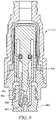
- Figure 3C shows a perspective view of an embodiment of base 208 illustrating the outlet port end of base 208.
- male luer 226 extends down through threaded connector 222 and includes the outlet port 203 of the fluid path though the connector.
- Channels 334 are formed in the end of male luer 226 to aid in the suction characteristics and fluid retraction of the connector upon disconnection as will be described in greater detail below. Channels 334 assist in the retraction of fluid upon disconnect by directing fluid into tapered end 217 of outlet port 203 throughout the disconnection process.
- top 204 includes an inlet port 202 for receiving the male luer of another compatible device.
- cavity 223 receives elastic cup and barb, and as will be discussed, provides room for barb 206 from Figure 2 to move longitudinally within cavity 223.
- Cavity 223 also includes flow channels 327 molded into the internal walls of cavity 223. While the flow channels 223 are shown symmetrically spaced around the internal wall of cavity 223, any number, size, spacing or configuration of flow channels could be used without departing from the scope of the concepts described herein.
- the internal surface of cavity 223 of top 204 also includes elastic cup seat 328 which works cooperatively with seating ring seat 219 of base 208, shown in Figures 3A and 3B to hold seating ring 211 of elastic cup 205 in place when the medical connector is assembled.
- Base seat 329 mates with seat 221 from Figures 3A and 3B to assemble and seal top 204 to base 208.
- FIG. 6B is a sectional view of the medical connector shown in Figure 6A rotated 90° around its longitudinal axis.
- a preferred embodiment of medical connector 100 is formed by the assembly of top 204 to base 208. Within the cavity 223 formed by top 204 and base 208, barb 206 and elastic cup 205 are housed. Sealing ring 207 fits into sealing ring seat 214.
- Top fluid path 650 communicates with junction fluid path 651 and base fluid path 652, using channel 220, before arriving at post fluid path 653 which is in communication with outlet port 203 in male luer portion 226 of connector 100.
- fluid paths 650, 651, 652, through 653 channel flow around elastic cup 205, through channel 220 in base 208 and around post 216 of barb 206. This fluid path allows for the sealing of male luer 226 using tapered end 217 of post 216.
- Top 212 of barb 206 fits into the cavity created by elastic cup 205.
- a ridge, or seating surface 328 formed in the inner wall of top 204 between the flow channels mates with the top surface of seating ring 211, while the bottom surface of seating ring 211 mates with seating ring seat 219 in base 208.
- seating ring 211 of elastic cup 205 is held firmly in place between top 204 and base 208.
- Cup portion 648 of elastic cup 205 may deform or stretch up into cavity 223 of top 204.
- Cup portion 648 also acts to place tension on barb 206, acting to force barb 206 toward base 208 which acts to force tapered end of post 216 into tapered channel 647 of male luer 226.
- tapered end 217 is pressed into tapered channel 647, male luer 226 is blocked, thereby preventing fluid flow through medical connector 100.
- the embodiment of base 208 shown includes vent holes 646a and 646b.
- Barb arms 213a and 213b extend downward through vent holes 646a and 646b and protrude into the cavity forming threaded connector 222.
- Sealing ring 207 prevents fluid in fluid path 652 from flowing up and into vents 646a and 646b.
- barb arms 213a and 213b can be engaged by a surface of a male luer to push barb 206 and cup 648 up into cavity 223 extracting tapered end 217 of post 216 from tapered channel 647 of male luer 226 and thereby opening the flow path through medical connector 100.
- Medical connector 100 in accordance with the concepts described herein, includes a closed male luer that prevents fluid flow until activated by insertion into a complimentary female luer connector.
- elastic cup 205 places a positive pressure on barb 206, thereby keeping tapered end 217 of post 216 firmly seated in male luer 226 of base 208.
- Barb arms 213a and 213b extend through vent holes 646a and 646b, respectfully, and into the cavity form by connector 222.
- Female connector 700 includes female luer 703 which includes threaded connector 704 and top surface 701. As can be seen, when female connector 700 is threaded onto medical connector 100 such that male luer 226 engages with female luer 703, top surface 701 of female connector 700 will engage the bottom surfaces 702a and 702b of barb arms 213a and 213b, respectively. As female connector 700 continues to be threaded into medical connector 100, the engagement of top surface 701 with barb arms 213a and 213b will force barb 206 up into medical connector 100, elongating elastic cup 205.
- FIGS 8A and 8B sectional views of the embodiment of medical connector 100 shown in Figure 1 are shown activated by the complimentary connector 700 of Figure 7 .
- the term activate or activated, as used herein has the same meaning a connected or engaged, while the term deactivated has the same meaning as disconnected or disengaged.
- top surface 701 of female connector 700 engages barb arms 213a and 213b of barb 206.
- fluid path when medical connector 100 is engaged with female connector 700 can be seen clearly in Figure 8B with reference to elements in Figure 8A .
- fluid enters through inlet port 202 and flows into cavity 223 of top 204. Fluid continues in top fluid path 650 which flows through flow channels 327 as described with respect to Figure 4 . Fluid continues through junction fluid path along flow channels 330 also described with respect to Figure 4 and then into channels 220 through base 208 into fluid path 652. From channels 220 and fluid path 652, the fluid continues through post fluid path 653 which extends the along the length of male luer 226 between the inner surface of the male luer and post 216 of barb 206. Fluid then exits out of outlet port 203 through tapered channel 647 and flows into female connector 700.
- activation or connection of medical connector 100 to another device causes post 216 to push elastic cup 205 up into cavity 223 thereby decreasing the volume of cavity 223.
- cup 205 Upon deactivation or disconnection, the opposite occurs, cup 205 returns to its original state increasing the volume of cavity 223.
- This increase in the volume of cavity 223 has advantageous effects on the operation of medical connector 100. Namely, the increase in the fluid volume held by medical connector 100 at disconnection provides a suction force, or negative displacement force on the fluid on male luer 226, thereby drawing the fluid out of male luer 226 and into medical connector 100.
- Channels 334 in the end of male luer 226, as shown in Figure 3C provide a path for the suction force and fluid retraction into outlet port 203 as the connector is being disengaged. Without channels 334, the tip of male luer 226 could be closed by the receiving device until the moment of complete separation possibly preventing the fluid retraction before that moment.
- This suction acts to clean any fluid in the vicinity male luer opening, preventing leaks or drops escaping from the medical connector at disconnection, which is very important when working with blood or potentially harmful medicines such as those used in chemotherapy.
- Traditional connectors have required medical professionals to clamp a line in the system to prevent leakage upon disconnection. Such clamping, while potentially beneficial in that it would prevent the suction created by the increase in fluid volume at disconnection from drawing fluid from the source line, is not necessary with embodiments of connectors as described herein to prevent leakage or dripping.
- female connector 900 may also include a spike to cause activation of the closed male luer.
- Spike 901 engages bottom surface 902 of post 216 moving post 216 away from tapered channel 647.
- Spike 901 includes inlet ports 903 which allow fluid from medical connector to flow into channel 904 in spike 901.
- FIG. 10A-D illustrate embodiments of other medical connectors that use other mechanisms to force the post into a sealing position.
- Figure 10A shows an embodiment of a medical connector 1001 that replaces the elastic cup with a rigid cup 1002 and uses spring 1003 to provide the force against post 1004.
- Connector 1001 by using a rigid cup will providing a constant priming volume.
- Figure 10B shows a connector 1010 that uses an inverted bellows valve 1011 to provide the elastic force on post 1012. Slits 1014 in inverted bellows valve 1011 allow fluid to pass through and in to the fluid path. Additional seal 1013 is required to prevent fluid from flowing into the vent holes in the base.
- Figure 10C shows a embodiment of a medical connector 1020 substantially as described with respect to Figure 10B except that the inverted bellows valve is replaced with an inverted helix spring 1021.
- Figure 10D shows an alternate embodiment of a bellows valve.
- Medical connector 1030 uses a bellows valve 1031 as was described with respect to Figure 10B to provide the elastic force on post 1033. However, instead of using slits and passing the fluid through the bellows valve, connector 1030 includes a seal 1032 which directs the fluid over and around bellows valve 1031 and into the fluid path through connector 1030.
- the top, base and barb elements are preferably formed from polycarbonate plastic but could be formed from any number of materials appropriate for medical connectors.
- the elastic cup and the bellows described herein are preferably made from medical grade silicon, but can be made from any material that has the characteristics described with respect to those elements.
- the female connector used with a medical connector according to the concepts described herein may be any type of female connector such as those having a valve plug arrangement, bellows type plugs, devices with septums, or other configurations designed to accept standardized male luer connectors.
Description
- The present invention relates to medical connectors used in fluid delivery applications, and more specifically to connectors that minimize fluid leakage during connection and disconnection.
- Medical connections are widely used in fluid delivery systems such as those used in connection with intravenous fluid lines, blood access, hemodialysis, peritoneal dialysis, enteral feeding, drug vial access, etc. Many prior art aseptic medical connections have been designed to puncture an elastomeric diaphragm or septum, which has one side in contact with the fluid, with a sharpened hollow hypodermic needle. The use of such hypodermic needles has been gradually decreasing as a result of both safety and cost considerations associated with infectious disease acquired from needle sticks. These connectors have been replaced with luer activated connectors which don't require hypodermic needles, but instead use an activator such as a luer on the end of a syringe or IV line to create a fluid path though a valve in a connector. The removal of the connector causes the valve to close when the line is disconnected. Such a system is described in
United States Patent 5,569,235 to Ross et al . -
US 2004/124389 A1 discloses a self-sealing male Luer connector for connection with a female Luer connector. The male Luer connector includes a housing having a distally-projecting tubular male body and a surrounding cuff interconnected by a proximal wall in which is formed at least one activation opening. A valve plug is slidably installed within the housing and formed with a distal end configured to sealingly engage the distal end of the male body's interior flow passage and with at least one activation arm at its proximal end configured to extend through the activation opening into the cavity formed between the male body and the cuff. An elastomeric device is sealingly configured within the activation opening about the activation arm to secure the valve plug in position and bias it distally. The proximal end of the male Luer connector may be configured as a conventional female connector, a blood collection device, or other such device. -
WO 2007/008511 A2 discloses a luer connector including a housing with first end including a male luer tip and a second end. The connector further includes a rigid valve member having a first opened end and a second closed end and a retaining member configured to couple the valve member and the housing. The housing further includes a rigid conduit positioned within the housing and in fluid communication with the second end of the housing, the rigid conduit adapted to engage the first opened end of the valve member. The housing including a first internal volume when the valve member is in a first position and a second, smaller volume when the valve member is in a second position. -
WO 2006/062912 A1 discloses a self-sealing male Luer connector which attaches to any standard female Luer valve to open a flow channel between the two. The self-sealing male Luer connector includes a rigid housing having a distal end with a rigid male Luer connector and a proximal end at which a proximal seal is formed. The distal end of the housing includes a valve seat. Located within the housing is a resilient biasing member that biases an actuator into contact with the valve seat to prevent fluid flow through the male connector. Upon engagement with a female connector, the actuator is moved in the proximal direction to open the distal valve and then the proximal seal. A partial vacuum is formed within the male connector upon disengagement with the female connector that draws any fluids on the external surface of the distal end of the male Luer connector into the male tip. -
WO 2005/107847 A1 discloses a positive pressure one way medical valve containing an inlet, outlet, an internal flow path between the inlet and the outlet and a plunger movable between a retraced sealing position. The plunger is moved from the retraced to the extended position by insertion of a tip onto the inlet. A variable volume chamber is defined partially by an elastomeric member that is stretched, when plunger is in the extended position and reduced, when the plunger is in the retraced position so to increase or decrease the volume of the chamber respectively. A valve, which is movable between open and closed positions by the presence or absence of fluid passing through the inlet, immediately seals the flow pathway before the plunger is retraced. - Typical connectors and valves of this type, such as described by Ross, have many attributes that are not ideal in medical applications for delivery of fluids that could be harmful if contacted by the health care provider or the patient other than through the patient's intravenous ("IV") connection. Oncology drugs such as chemotherapy are examples of fluids that while beneficial to the patient as part of a treatment regimen could be extremely harmful to the health care provider if the chemotherapy drug were to come into contact with the skin of the health care provider or patient.
- Traditional medical connectors require the health care provider to exercise great care on connection or disconnection due to the likelihood of the drug remaining inside the connector or dripping, particularly on disconnection when the connectors are primed with fluid. Some female connectors are designed to push fluid in the throat of the connector to the surface during disconnection. While this is desirable for aseptic connectors to provide a swabbable surface, it can result in fluid drips from the device on disconnection. Other connectors use a membrane with a septum that can also allow fluids to escape the connector.
- What is needed is a connector for medical fluids that has standardized connections for use with existing medical connectors and also minimizes or eliminates drips on connection or disconnection.
- The invention is defined in independent claim 1. Advantageous embodiments are subject of the dependent claims.
- Embodiments of the concepts described herein describe a medical connector which is formed by a body having an inlet port, an outlet port through a male luer portion of the body, and a fluid path between the inlet port and the at least one outlet ports. A retractable post extends through the fluid path in the male luer sealing a tip of the male luer thereby closing the fluid path when the connector in not activated. Barbs extending along the exterior of the male luer and connected to the retractable post, wherein when the connector is activated, the barbs force the retractable post away from the tip of the male luer thereby opening the fluid path through the medical connector. A retention member applies force to the post to force the post to seal the tip of the male luer when the medical connector is not activated.
- In another embodiment of the concepts described herein a method for activating a medical connector is described. The medical connector includes a body having an inlet port and an outlet port the outlet port being part of a male luer. The connector further includes a post extending through a flow channel in the male luer and one or more barb arms connected to the post and adjacent to an outer surface of the male luer. The method includes inserting the male luer of the medical connector into a female luer of a secondary device, engaging the barb arms of the medical connector with a surface of the female luer, and retracting the post from the outlet port of the medical connector in response to the engagement of the barb arm with the female luer, wherein the retraction of the post from the outlet port opens a fluid path through the medical connector.
- In another embodiment a closed male luer medical connector is described which includes a body formed by a top and a base, the body having an internal cavity and flow channels formed in walls of the internal cavity, the body further having an inlet port and an outlet port, the outlet port including a male luer, wherein the male luer defines a flow channel along its length. The connector also includes a body having a top in the internal cavity of the body; a post extending from the top and having a portion that extends the length of the flow channel, a tip of the post sized to seal the male luer thereby closing the flow channel when the post is fully extended into the male luer, the post further comprising one or more barb arms extending through vent holes in the body and adjacent to an external surface of the male luer, and an elastic cup, the elastic cup having a seating ring held in a fixed position by the body and a cup extending into the internal cavity and receiving the top of the post. Pressure applied to the barb arms in a direction parallel to the male luer and away from the outlet port results in the top of the body being forced up into the internal cavity and the post being drawn out of the outlet port, thereby unsealing the male luer, opening the flow channel through the medical connector. The elastic cup applies tension to the post body, the tension forcing the post back into the sealed position when the force on the barb arms is removed.
- The foregoing has outlined rather broadly the features and technical advantages of the present invention in order that the detailed description of the invention that follows may be better understood. Additional features and advantages of the invention will be described hereinafter which form the subject of the claims of the invention. It should be appreciated by those skilled in the art that the conception and specific embodiment disclosed may be readily utilized as a basis for modifying or designing other structures for carrying out the same purposes of the present invention. It should also be realized by those skilled in the art that such equivalent constructions do not depart from the spirit and scope of the invention as set forth in the appended claims. The novel features which are believed to be characteristic of the invention, both as to its organization and method of operation, together with further objects and advantages, will be better understood from the following description when considered in connection with the accompanying figures. It is to be expressly understood, however, that each of the figures is provided for the purpose of illustration and description only and is not intended as a definition of the limits of the present invention.
- For a more complete understanding of the present invention, reference is now made to the following descriptions taken in conjunction with the accompanying drawing, in which:
-
Figure 1 is a side view of an embodiment of a male luer medical connector for fluid delivery according to the concepts described herein; -
Figure 2 is an exploded view of the embodiment of a male luer medical connector shown inFigure 1 ; -
Figures 3A and 3B are side views of an embodiment of the base of the male luer medical connector shown inFigure 2 -
Figure 3C is a perspective view showing the outlet port of an embodiment of the base of the male luer connector shown inFigure 2 ; -
Figure 4 is a sectional view of an embodiment of the top of the male luer medical connector show inFigure 2 ; -
Figure 5 is a side view of an embodiment of the barb of the male luer medical connector shown inFigure 2 ; -
Figure 6A is a section view of the male luer medical connector fromFigure 1 ; -
Figure 6B is a section view of the male luer medical connector shown inFigure 1 rotated 90° along its longitudinal axis from the view inFigure 6A ; -
Figure 7 is a sectional view of the male luer medical connector fromFigure 1 illustrating the relationship between the male luer of the medical connector and a female luer connector and the fluid path through the connector; -
Figure 8A and8B are sectional views of the male luer medical connector fromFigure 1 illustrating the barb engaging the female luer connector and opening the fluid path through the connector; -
Figure 9 is a sectional view of the medical connector fromFigure 1 illustrating an alternative mechanism for opening the fluid path through the connector; and -
Figures 10A-10D are alternate embodiments of a male luer medical connector according to the concepts described herein. - Referring now to
Figure 1 , an embodiment of amedical connector 100 in accordance with the concepts described herein is shown.Medical connector 100 operates as a needleless access device and has abody 101 with afemale access port 102 and amale lure 103. Themale luer 103 is ISO compatible and compliant and interfaces with standard needless access devices.Medical connector 100 differs from access devices in thatmale luer 103 is closed, thereby preventing any fluid flow or leakage until activated by being inserted into a female luer. Whileconnector 100 is shown with a threaded female luer at its distal end any type of inlet port could be used while remaining within the concepts described herein. Such inlet ports could include know connections for any type of fluid delivery sources or devices such as IV fluid bags, pumps or the like. - As with traditional needleless medical connectors,
male luer 103 ofmedical connector 100 is inserted into the female luer of another needleless access device to create a fluid path between a fluid delivery mechanism and a patient. In order to avoid drips and leakage of medical fluids that may be harmful to health care providers or patients,medical connector 100 is designed to minimize or eliminate fluid drips or leakage upon connection ofmedical connector 100 with another access device, or particularly upon disconnection from another access device with both devices are primed with fluid. - Referring now to
Figure 2 , the embodiment of themedical connector 100 shown inFigure 1 is shown in an exploded view. Embodiments of the components that formmedical connector 100 shown. The body ofmedical connector 100 includes top 204 having aninlet port 202 and abase 208, which includesoutlet port 203. The medical connector also includes anelastic cup 205 formed from an elastic deformable material, abarb 206, and asealing ring 207. - Top 204 can form a majority of the body of
medical connector 100.Top 204 includes threadedfemale luer 209 which connects to the male luer of any other compatible device.Female luer 209 can be threaded to maintain the connection between devices. Whileconnector 209 is shown as having a threaded female luer type connector, any type of inlet port could be used, such as a bond pocket or other connector, while remaining within the scope of the concepts described herein. Top 100 can also includeridges 210 along the outer surface oftop 204.Ridges 204 provide for enhanced gripping surfaces when twisting forces are applied tomedical connector 100 during connection and disconnection with other devices. Top 204 also includescavity 223 which holdselastic cup 205 andbarb 206 as will be described. -
Elastic cup 205 is formed from an elastic deformable material allowing it to stretch and then return to its original state.Elastic cup 205 fits intocavity 223 of top 204 and includescup cavity 224 for receiving top 212 ofbarb 206. Seatingring 211 is used to holdelastic cup 205 between top 204 andbase 208. -
Barb 206, which may also be referred to as a post body, is used to open and close the fluid path throughmedical connector 100 as will be described. Additional reference is made toFigure 5 in the description ofbarb 206.Barb 206 includes top 212 which fits intoelastic cup 205.Barb arms Sealing ring seat 214 receives sealingring 207, which is held in place byflange 215.Post 216 extend downward from the center of top 212 parallel tobarb arms Post 216 includestapered end 217 which mates with theend outlet port 203 inbase 208.Bumps 218 arranged around the circumference ofpost 216 keeppost 216 centered inbase 208 and provide space for fluid to flow aroundpost 216 ofbarb 206. -
Base 208 mates with top 204 thereby holdingelastic cup 205,barb 206 and sealingring 207 incavity 223 oftop 204.Top 204 is secured to the base 208 using conventional means, such as solvent bonding, ultrasonics, spin welding, etc.Base 208 includeschannel 225 which receives post 216 ofbarb 206. - Referring additionally to
Figures 3A and 3B which show side views of an embodiment ofbase 208 fromFigure 2 ,base 208 will be described in greater detail.Base 208 includeschannel 225 which receives post 216 ofbarb 206.Sealing ring seat 219 engages the bottom surface ofseating ring 211 to holdelastic cup 205 in place whenmedical connector 100 is assembled. Seatingsurface 221 mates with a corresponding surface (not shown) intop 204 to sealmedical connector 100 except for the proscribed fluid path.Flow channels 220 allow for fluid flow through the base and intooutlet port 203. While two channels are shown inbase 208, any number of channels, including one or three or more, can be used without departing from the scope of the concepts described herein.Base 208 also includesmale luer 226 and threadedconnector 222. -
Figure 3C shows a perspective view of an embodiment ofbase 208 illustrating the outlet port end ofbase 208. As described,male luer 226 extends down through threadedconnector 222 and includes theoutlet port 203 of the fluid path though the connector.Channels 334 are formed in the end ofmale luer 226 to aid in the suction characteristics and fluid retraction of the connector upon disconnection as will be described in greater detail below.Channels 334 assist in the retraction of fluid upon disconnect by directing fluid into taperedend 217 ofoutlet port 203 throughout the disconnection process. - Referring now to
Figure 4 , an embodiment of top 204 is shown in a sectional view. As described, top 204 includes aninlet port 202 for receiving the male luer of another compatible device. As described with respect toFigure 2 ,cavity 223 receives elastic cup and barb, and as will be discussed, provides room forbarb 206 fromFigure 2 to move longitudinally withincavity 223.Cavity 223 also includesflow channels 327 molded into the internal walls ofcavity 223. While theflow channels 223 are shown symmetrically spaced around the internal wall ofcavity 223, any number, size, spacing or configuration of flow channels could be used without departing from the scope of the concepts described herein. - The internal surface of
cavity 223 of top 204 also includeselastic cup seat 328 which works cooperatively withseating ring seat 219 ofbase 208, shown inFigures 3A and 3B to holdseating ring 211 ofelastic cup 205 in place when the medical connector is assembled.Base seat 329 mates withseat 221 fromFigures 3A and 3B to assemble and seal top 204 tobase 208. - Referring now to
Figures 6A and6B , an embodiment of amedical connector 100 is shown assembled in section view.Figure 6B is a sectional view of the medical connector shown inFigure 6A rotated 90° around its longitudinal axis. As has been described, a preferred embodiment ofmedical connector 100 is formed by the assembly of top 204 tobase 208. Within thecavity 223 formed by top 204 andbase 208,barb 206 andelastic cup 205 are housed.Sealing ring 207 fits into sealingring seat 214. - Top
fluid path 650 communicates withjunction fluid path 651 and basefluid path 652, usingchannel 220, before arriving atpost fluid path 653 which is in communication withoutlet port 203 inmale luer portion 226 ofconnector 100. Unlike other similar medical connectors in which the fluid path flows directly from an inlet port through a channel inside a post and out the end of the outlet port in a male luer,fluid paths elastic cup 205, throughchannel 220 inbase 208 and aroundpost 216 ofbarb 206. This fluid path allows for the sealing ofmale luer 226 usingtapered end 217 ofpost 216. -
Top 212 ofbarb 206 fits into the cavity created byelastic cup 205. A ridge, orseating surface 328 formed in the inner wall of top 204 between the flow channels mates with the top surface ofseating ring 211, while the bottom surface ofseating ring 211 mates withseating ring seat 219 inbase 208. When assembledseating ring 211 ofelastic cup 205 is held firmly in place betweentop 204 andbase 208.Cup portion 648 ofelastic cup 205 may deform or stretch up intocavity 223 oftop 204. -
Cup portion 648 also acts to place tension onbarb 206, acting to forcebarb 206 towardbase 208 which acts to force tapered end ofpost 216 into taperedchannel 647 ofmale luer 226. When taperedend 217 is pressed into taperedchannel 647,male luer 226 is blocked, thereby preventing fluid flow throughmedical connector 100. - Referring specifically to
Figure 6B , it can be seen that the embodiment ofbase 208 shown includesvent holes Barb arms vent holes connector 222.Sealing ring 207 prevents fluid influid path 652 from flowing up and intovents barb arms barb 206 andcup 648 up intocavity 223 extractingtapered end 217 ofpost 216 from taperedchannel 647 ofmale luer 226 and thereby opening the flow path throughmedical connector 100. - Referring now to
Figure 7 , a sectional view of the embodiment ofmedical connector 100 shown inFigure 1 is described in relation to acomplimentary connector 700.Medical connector 100, in accordance with the concepts described herein, includes a closed male luer that prevents fluid flow until activated by insertion into a complimentary female luer connector. As described,elastic cup 205 places a positive pressure onbarb 206, thereby keepingtapered end 217 ofpost 216 firmly seated inmale luer 226 ofbase 208.Barb arms vent holes connector 222. -
Female connector 700 includesfemale luer 703 which includes threadedconnector 704 andtop surface 701. As can be seen, whenfemale connector 700 is threaded ontomedical connector 100 such thatmale luer 226 engages withfemale luer 703,top surface 701 offemale connector 700 will engage thebottom surfaces barb arms female connector 700 continues to be threaded intomedical connector 100, the engagement oftop surface 701 withbarb arms barb 206 up intomedical connector 100, elongatingelastic cup 205. - Referring now to
Figures 8A and8B , sectional views of the embodiment ofmedical connector 100 shown inFigure 1 are shown activated by thecomplimentary connector 700 ofFigure 7 . The term activate or activated, as used herein has the same meaning a connected or engaged, while the term deactivated has the same meaning as disconnected or disengaged. As described with reference toFigure 7 , whenmale luer 226 is activated byfemale connector 700 by inserting male luer intofemale connector 700,top surface 701 offemale connector 700 engagesbarb arms barb 206. Asbarb 206 is pushed upward intocavity 223 of top 204, seating ring is held in place between the opposing surfaces of top 204 andbase 208 whilecup 648 ofelastic cup 205 stretches to accommodate the rise ofbarb 206. The rise ofbarb 206 results in the rise ofpost 216 causingtapered end 217 to disengage from taperedchannel 647 creating an open fluid path from medical connector inlet port throughoutlet port 203 and intofemale connector 700. The deformation ofelastic cup 205 provides tension onbarb 206 so that whenfemale connector 700 is removed frommale luer 226, the force supplied byelastic cup 205 causesbarb 206 to return to the closed position with tapered end ofpost 216 again sealing taperedchannel 647 ofmale luer 226. - The fluid path when
medical connector 100 is engaged withfemale connector 700 can be seen clearly inFigure 8B with reference to elements inFigure 8A . In the open fluid path configuration, fluid enters throughinlet port 202 and flows intocavity 223 oftop 204. Fluid continues in topfluid path 650 which flows throughflow channels 327 as described with respect toFigure 4 . Fluid continues through junction fluid path alongflow channels 330 also described with respect toFigure 4 and then intochannels 220 throughbase 208 intofluid path 652. Fromchannels 220 andfluid path 652, the fluid continues throughpost fluid path 653 which extends the along the length ofmale luer 226 between the inner surface of the male luer and post 216 ofbarb 206. Fluid then exits out ofoutlet port 203 through taperedchannel 647 and flows intofemale connector 700. - As can be seen from
Figures 8A and8B , activation or connection ofmedical connector 100 to another device causes post 216 to pushelastic cup 205 up intocavity 223 thereby decreasing the volume ofcavity 223. Upon deactivation or disconnection, the opposite occurs,cup 205 returns to its original state increasing the volume ofcavity 223. This increase in the volume ofcavity 223 has advantageous effects on the operation ofmedical connector 100. Namely, the increase in the fluid volume held bymedical connector 100 at disconnection provides a suction force, or negative displacement force on the fluid onmale luer 226, thereby drawing the fluid out ofmale luer 226 and intomedical connector 100.Channels 334 in the end ofmale luer 226, as shown inFigure 3C provide a path for the suction force and fluid retraction intooutlet port 203 as the connector is being disengaged. Withoutchannels 334, the tip ofmale luer 226 could be closed by the receiving device until the moment of complete separation possibly preventing the fluid retraction before that moment. - This suction acts to clean any fluid in the vicinity male luer opening, preventing leaks or drops escaping from the medical connector at disconnection, which is very important when working with blood or potentially harmful medicines such as those used in chemotherapy. Traditional connectors have required medical professionals to clamp a line in the system to prevent leakage upon disconnection. Such clamping, while potentially beneficial in that it would prevent the suction created by the increase in fluid volume at disconnection from drawing fluid from the source line, is not necessary with embodiments of connectors as described herein to prevent leakage or dripping.
- Referring now to
Figure 9 , and alternate embodiment of a female connector for activating a closed male luermedical connector 100 according to the concepts describe herein is shown. WhileFigures 8A and8B demonstrate a closed male luer medical connector according to the concepts described herein being opened using the bard arms ofbarb 206 fromFigure 2 ,female connector 900 may also include a spike to cause activation of the closed male luer.Spike 901 engagesbottom surface 902 ofpost 216 movingpost 216 away from taperedchannel 647.Spike 901 includesinlet ports 903 which allow fluid from medical connector to flow intochannel 904 inspike 901. - While
medical connector 100 shown inFigures 2-9 uses the elastic nature ofelastic cup 205 to forcebarb 206 into a closed position when not engaged with a female connector, other mechanisms may be used to accomplish the same purpose without departing from the concepts described herein.Figures 10A-D illustrate embodiments of other medical connectors that use other mechanisms to force the post into a sealing position. -
Figure 10A shows an embodiment of amedical connector 1001 that replaces the elastic cup with arigid cup 1002 and usesspring 1003 to provide the force againstpost 1004.Connector 1001, by using a rigid cup will providing a constant priming volume.Figure 10B shows aconnector 1010 that uses an inverted bellowsvalve 1011 to provide the elastic force onpost 1012.Slits 1014 ininverted bellows valve 1011 allow fluid to pass through and in to the fluid path.Additional seal 1013 is required to prevent fluid from flowing into the vent holes in the base. -
Figure 10C shows a embodiment of amedical connector 1020 substantially as described with respect toFigure 10B except that the inverted bellows valve is replaced with aninverted helix spring 1021.Figure 10D shows an alternate embodiment of a bellows valve.Medical connector 1030 uses abellows valve 1031 as was described with respect toFigure 10B to provide the elastic force onpost 1033. However, instead of using slits and passing the fluid through the bellows valve,connector 1030 includes aseal 1032 which directs the fluid over and around bellowsvalve 1031 and into the fluid path throughconnector 1030. - The top, base and barb elements are preferably formed from polycarbonate plastic but could be formed from any number of materials appropriate for medical connectors. The elastic cup and the bellows described herein are preferably made from medical grade silicon, but can be made from any material that has the characteristics described with respect to those elements. The female connector used with a medical connector according to the concepts described herein may be any type of female connector such as those having a valve plug arrangement, bellows type plugs, devices with septums, or other configurations designed to accept standardized male luer connectors.
- Although the present invention and its advantages have been described in detail, it should be understood that various changes, substitutions and alterations can be made herein without departing from the scope of the invention which is defined by the appended claims. Moreover, the scope of the present application is not intended to be limited to the particular embodiments of the process, machine, manufacture, composition of matter, means, methods and steps described in the specification. As one of ordinary skill in the art will readily appreciate from the disclosure of the present invention, processes, machines, manufacture, compositions of matter, means, methods, or steps, presently existing or later to be developed that perform substantially the same function or achieve substantially the same result as the corresponding embodiments described herein may be utilized according to the present invention.
Claims (15)
- A medical connector (100) comprising:a body (101) having an internal cavity (223), an inlet port (202), at least one outlet port (203) through a male luer portion (226) of the body (101), and a fluid path extending from the inlet port (202) to the at least one outlet port (203);a retractable post extending through the fluid path in the male luer (226) sealing a tip of the male luer (226) thereby closing the fluid path when the connector (100) is not activated, and one or more barb arms (213a, 213b) extending through vent holes in the body and along the exterior of the male luer (226) and being connected to the retractable postat a top of the barb (212);a first seal comprising an elastic cup (648) having a seating ring (211) the seating ring (211 being coupled to the body (101) with the elastic cup(648) extending into the internal cavity (223) and receiving the top of the barb (212), the first seal configured to form an internal fluid volume of the internal cavity (223) between the seal and the inlet port, the fluid path passing through the internal fluid volume;wherein, the connector (100) is activated when a pressure is applied to the one or more barb arms (213a, 231b) in a direction away from the outlet port (203) such that the retractable post is forced away from the tip of the male luer (226), thereby biasing the elastic cup (648) of
the first seal further into the internal cavity (223), opening the fluid path through the medical connector (100) and decreasing the internal fluid volume, and the connector (100) is deactivated when the pressure is removed from the one or more barb arms (213a, 213b) such the elastic cup (648) moves the retractable post toward the tip of the male luer (226), thereby increasing the internal fluid volume and closing the fluid path through the medical connector (100). - The medical connector (100) of claim 1, wherein, when the connector (100) is deactivated, fluid in and around the male luer (226) is drawn into the medical connector (100).
- The medical connector (100) of claim 1 or 2, wherein the first seal directs tension to the retractable post, such that the retractable post is held in a closed position such that the tip of the male luer (226) is sealed when the connector (100) is not activated and moves the retractable post to the closed position when the connector (100) is deactivated.
- The medical connector (100) of claim 3, wherein the first seal comprises an elastic bellows.
- The medical connector (100) of any of the preceding claims, wherein the body (101) is formed by a top (204) having the inlet port (202) and a base (208) having the male luer (226).
- The medical connector (100) of claim 5, wherein:the one or more barb arms (213a, 213b) extend through vent holes (646a, 646b) in the base (208); and/orthe base (208) includes channels that allow fluid to flow to the male luer (226).
- The medical connector (100) of any of the preceding claims, further comprising flow channels (327) formed in an interior wall of the body (101).
- The medical connector of claim 1,wherein the barb comprises a barb top (212), andthe seating ring (211) is held in a fixed position by the body (101) with the cup portion (648) extending into the internal cavity (223) and receiving the barb top (212) therein;wherein the retractable post extends from the barb top (212) and has a tip sized to seal the male luer (226) when the connector (100) is deactivated; andwherein, when the connector (100) is activated, the barb top (212) is forced up into the internal cavity (223) and the tip of the retractable post is drawn out of the outlet port (203).
- The medical connector (100) of claim 8, wherein:the internal fluid volume is increased upon deactivation of the medical connector (100) as a result of the elastic cup (205) returning to it deactivated state, such that the fluid in and around the male luer (223) is drawn back into the medical connector (100) upon deactivation; and/ora sealing ring (207) is seated on the retractable post to prevent fluid flow along the retractable post in a direction away from the outlet port (203).
- The medical connector of claim 8 or 9, wherein:
pressure applied to the barb arms (213a, 213b) is applied by a top surface of a female luer; and/or pressure is applied to the post by a spike in a female luer. - A method for activating a medical connector (100) of anyone of claims 1 to 10, the method comprising:inserting the male luer (226) of the medical connector into a female luer of a secondary device;engaging the barb arms (213a, 213b) of the medical connector with a surface of the female luer; andretracting the post from the outlet port (203) of the medical connector (100) in response to the engagement of the barb arms (213a, 213b) with the female luer, wherein the retraction of the post from the outlet port (203) opens a fluid path from the inlet port (202) through an internal fluid volume of the medical connector (100) while decreasing the internal fluid volume.
- The method of claim 11, wherein the cup portion (648) of the first seal urges the retractable post toward the tip of the male luer (226) when the connector (100) is not activated and returns the retractable post ato the closed position upon being deactivated.
- The method of claim 11 or 12, further comprising:returning the post into the outlet port (203) using force applied to the post by the tension member when the medical connector (100) is deactivated; and/orincreasing the internal fluid volume of the medical connector (100) upon deactivation of the medical connector (100) such that fluid in and around the male luer (226) is drawn back into the medical connector (100) upon deactivation.
- The method of claim 11, 12 or 13 wherein the tension member is one of: an elastic cup (205), a spring and an elastic bellows.
- The method of claim 11, wherein engaging the barb arms (213a, 213b) of the medical connector (100) with a surface of the female luer is replaced by engaging the tip of the post with a spike in the female luer.
Priority Applications (1)
| Application Number | Priority Date | Filing Date | Title |
|---|---|---|---|
| EP22197426.4A EP4129361A1 (en) | 2009-04-06 | 2010-02-05 | Closed male luer device for use with needleless access devices |
Applications Claiming Priority (2)
| Application Number | Priority Date | Filing Date | Title |
|---|---|---|---|
| US12/418,809 US8182452B2 (en) | 2009-04-06 | 2009-04-06 | Closed male luer device for use with needleless access devices |
| PCT/US2010/023337 WO2010117484A1 (en) | 2009-04-06 | 2010-02-05 | Closed male luer device for use with needleless access devices |
Related Child Applications (2)
| Application Number | Title | Priority Date | Filing Date |
|---|---|---|---|
| EP22197426.4A Division EP4129361A1 (en) | 2009-04-06 | 2010-02-05 | Closed male luer device for use with needleless access devices |
| EP22197426.4A Division-Into EP4129361A1 (en) | 2009-04-06 | 2010-02-05 | Closed male luer device for use with needleless access devices |
Publications (3)
| Publication Number | Publication Date |
|---|---|
| EP2416825A1 EP2416825A1 (en) | 2012-02-15 |
| EP2416825A4 EP2416825A4 (en) | 2017-10-04 |
| EP2416825B1 true EP2416825B1 (en) | 2022-11-09 |
Family
ID=42826791
Family Applications (2)
| Application Number | Title | Priority Date | Filing Date |
|---|---|---|---|
| EP22197426.4A Pending EP4129361A1 (en) | 2009-04-06 | 2010-02-05 | Closed male luer device for use with needleless access devices |
| EP10762014.8A Active EP2416825B1 (en) | 2009-04-06 | 2010-02-05 | Closed male luer device for use with needleless access devices |
Family Applications Before (1)
| Application Number | Title | Priority Date | Filing Date |
|---|---|---|---|
| EP22197426.4A Pending EP4129361A1 (en) | 2009-04-06 | 2010-02-05 | Closed male luer device for use with needleless access devices |
Country Status (13)
| Country | Link |
|---|---|
| US (6) | US8182452B2 (en) |
| EP (2) | EP4129361A1 (en) |
| JP (1) | JP5805067B2 (en) |
| KR (3) | KR101702150B1 (en) |
| CN (1) | CN102573953B (en) |
| AU (6) | AU2010235092B2 (en) |
| BR (2) | BR122020007742B1 (en) |
| CA (1) | CA2757572C (en) |
| ES (1) | ES2937268T3 (en) |
| MX (1) | MX2011010339A (en) |
| RU (1) | RU2531647C2 (en) |
| SG (1) | SG175027A1 (en) |
| WO (1) | WO2010117484A1 (en) |
Families Citing this family (86)
| Publication number | Priority date | Publication date | Assignee | Title |
|---|---|---|---|---|
| US6695817B1 (en) | 2000-07-11 | 2004-02-24 | Icu Medical, Inc. | Medical valve with positive flow characteristics |
| US7600530B2 (en) | 2004-08-09 | 2009-10-13 | Medegen, Inc. | Connector with check valve and method of use |
| US10478607B2 (en) | 2004-08-09 | 2019-11-19 | Carefusion 303, Inc. | Connector for transferring fluid and method of use |
| CN101068592B (en) | 2004-11-05 | 2010-12-08 | Icu医疗公司 | Medical connector with the property of high flow rate |
| US9168366B2 (en) | 2008-12-19 | 2015-10-27 | Icu Medical, Inc. | Medical connector with closeable luer connector |
| EP2411715B1 (en) * | 2009-03-22 | 2019-01-30 | Elcam Medical Agricultural Cooperative Association Ltd. | Closed male luer connector |
| US8454579B2 (en) | 2009-03-25 | 2013-06-04 | Icu Medical, Inc. | Medical connector with automatic valves and volume regulator |
| US8182452B2 (en) * | 2009-04-06 | 2012-05-22 | Carefusion 303, Inc. | Closed male luer device for use with needleless access devices |
| IL201323A0 (en) | 2009-10-01 | 2010-05-31 | Medimop Medical Projects Ltd | Fluid transfer device for assembling a vial with pre-attached female connector |
| IL202070A0 (en) | 2009-11-12 | 2010-06-16 | Medimop Medical Projects Ltd | Inline liquid drug medical device |
| IL202069A0 (en) | 2009-11-12 | 2010-06-16 | Medimop Medical Projects Ltd | Fluid transfer device with sealing arrangement |
| US8753325B2 (en) | 2010-02-24 | 2014-06-17 | Medimop Medical Projects, Ltd. | Liquid drug transfer device with vented vial adapter |
| EP2512399B1 (en) | 2010-02-24 | 2015-04-08 | Medimop Medical Projects Ltd. | Fluid transfer assembly with venting arrangement |
| USD644731S1 (en) | 2010-03-23 | 2011-09-06 | Icu Medical, Inc. | Medical connector |
| US8298196B1 (en) | 2010-03-24 | 2012-10-30 | Mansour George M | Needleless access connector and method of use |
| US8758306B2 (en) | 2010-05-17 | 2014-06-24 | Icu Medical, Inc. | Medical connectors and methods of use |
| IL209290A0 (en) | 2010-11-14 | 2011-01-31 | Medimop Medical Projects Ltd | Inline liquid drug medical device having rotary flow control member |
| GB2503162B (en) | 2011-03-23 | 2018-08-22 | Nxstage Medical Inc | Peritoneal dialysis systems and devices |
| US9861733B2 (en) | 2012-03-23 | 2018-01-09 | Nxstage Medical Inc. | Peritoneal dialysis systems, devices, and methods |
| IL212420A0 (en) | 2011-04-17 | 2011-06-30 | Medimop Medical Projects Ltd | Liquid drug transfer assembly |
| TWI626063B (en) * | 2011-06-03 | 2018-06-11 | 凱爾福郡303股份有限公司 | Positive-displacement needleless access connector and method for manufacturing the same |
| JP6553357B2 (en) | 2011-09-09 | 2019-07-31 | アイシーユー・メディカル・インコーポレーテッド | Medical connector with fluid-resistant mating interface |
| IL215699A0 (en) | 2011-10-11 | 2011-12-29 | Medimop Medical Projects Ltd | Liquid drug reconstitution assemblage for use with iv bag and drug vial |
| USD711516S1 (en) | 2011-12-09 | 2014-08-19 | John Guest International Limited | Fluid connector |
| USD712014S1 (en) * | 2011-12-09 | 2014-08-26 | John Guest International Limited | Fluid connector |
| USD720451S1 (en) | 2012-02-13 | 2014-12-30 | Medimop Medical Projects Ltd. | Liquid drug transfer assembly |
| USD737436S1 (en) | 2012-02-13 | 2015-08-25 | Medimop Medical Projects Ltd. | Liquid drug reconstitution assembly |
| IL219065A0 (en) | 2012-04-05 | 2012-07-31 | Medimop Medical Projects Ltd | Fluid transfer device with manual operated cartridge release arrangement |
| US9599240B2 (en) | 2012-06-28 | 2017-03-21 | Saint-Gobain Performance Plastics Corporation | Polymer bellows spring |
| IL221635A0 (en) | 2012-08-26 | 2012-12-31 | Medimop Medical Projects Ltd | Drug vial mixing and transfer device for use with iv bag and drug vial |
| IL221634A0 (en) | 2012-08-26 | 2012-12-31 | Medimop Medical Projects Ltd | Universal drug vial adapter |
| US9339438B2 (en) | 2012-09-13 | 2016-05-17 | Medimop Medical Projects Ltd. | Telescopic female drug vial adapter |
| USD734868S1 (en) | 2012-11-27 | 2015-07-21 | Medimop Medical Projects Ltd. | Drug vial adapter with downwardly depending stopper |
| US9308362B2 (en) | 2013-03-12 | 2016-04-12 | Carefusion 303, Inc. | Male luer with fluid path and vent path seals |
| US9278205B2 (en) | 2013-03-13 | 2016-03-08 | Carefusion 303, Inc. | Collapsible valve with internal dimples |
| US9144672B2 (en) | 2013-03-13 | 2015-09-29 | Carefusion 303, Inc. | Needleless connector with compressible valve |
| US9089682B2 (en) | 2013-03-14 | 2015-07-28 | Carefusion 303, Inc. | Needleless connector with support member |
| US9370651B2 (en) | 2013-03-13 | 2016-06-21 | Carefusion 303, Inc. | Needleless connector with reduced trapped volume |
| KR102263974B1 (en) | 2013-03-15 | 2021-06-10 | 아이씨유 메디칼 인코퍼레이티드 | Medical connector |
| US9212772B2 (en) * | 2013-03-15 | 2015-12-15 | Pacific Hospital Supply Co., Ltd | Needle free connector |
| IL225734A0 (en) | 2013-04-14 | 2013-09-30 | Medimop Medical Projects Ltd | Ready-to-use drug vial assemblages including drug vial and drug vial closure having fluid transfer member, and drug vial closure therefor |
| WO2014181328A1 (en) | 2013-05-10 | 2014-11-13 | Medimop Medical Projects Ltd | Medical devices including vial adapter with inline dry drug module |
| ITTO20130433A1 (en) * | 2013-05-29 | 2014-11-30 | Borla Ind | CONNECTOR FOR MEDICAL LINES |
| USD765837S1 (en) | 2013-08-07 | 2016-09-06 | Medimop Medical Projects Ltd. | Liquid transfer device with integral vial adapter |
| WO2015019343A1 (en) | 2013-08-07 | 2015-02-12 | Medimop Medical Projects Ltd | Liquid transfer devices for use with infusion liquid containers |
| USD767124S1 (en) | 2013-08-07 | 2016-09-20 | Medimop Medical Projects Ltd. | Liquid transfer device with integral vial adapter |
| EP2862587A1 (en) | 2013-10-15 | 2015-04-22 | Becton Dickinson France | Tip cap assembly for closing an injection system |
| JP7176834B2 (en) | 2013-12-11 | 2022-11-22 | アイシーユー・メディカル・インコーポレーテッド | check valve |
| US10773067B2 (en) | 2014-09-08 | 2020-09-15 | Neomed, Inc. | Enteral connectors having coupling features |
| US10576020B2 (en) | 2015-06-18 | 2020-03-03 | Neomed, Inc. | Syringe-to-syringe coupler |
| USD757933S1 (en) | 2014-09-11 | 2016-05-31 | Medimop Medical Projects Ltd. | Dual vial adapter assemblage |
| USD786427S1 (en) | 2014-12-03 | 2017-05-09 | Icu Medical, Inc. | Fluid manifold |
| USD793551S1 (en) | 2014-12-03 | 2017-08-01 | Icu Medical, Inc. | Fluid manifold |
| WO2016110838A1 (en) | 2015-01-05 | 2016-07-14 | Medimop Medical Projects Ltd | Dual vial adapter assemblages with quick release drug vial adapter for ensuring correct usage |
| JP6709777B2 (en) * | 2015-03-26 | 2020-06-17 | テルモ株式会社 | Male connector and infusion set |
| USD825746S1 (en) | 2015-06-18 | 2018-08-14 | Neomed, Inc. | Syringe-to-syringe coupler |
| EP3313490B8 (en) * | 2015-06-24 | 2021-03-31 | Linear Health Science, LLC | Tubing system |
| US9987479B2 (en) * | 2015-07-09 | 2018-06-05 | Carefusion 303, Inc. | Closed male luer device for use with needleless access devices |
| EP3424554B1 (en) | 2015-07-15 | 2023-11-22 | Avent, Inc. | Enteral adaptor couplings |
| BR112018000062B1 (en) | 2015-07-16 | 2022-05-03 | Medimop Medical Projects Ltd | Liquid drug transfer device for secure flexible telescopic fit into injection vial |
| US10195415B2 (en) * | 2015-09-21 | 2019-02-05 | Carefusion 303, Inc. | Priming device |
| USD801522S1 (en) | 2015-11-09 | 2017-10-31 | Medimop Medical Projects Ltd. | Fluid transfer assembly |
| US10278897B2 (en) | 2015-11-25 | 2019-05-07 | West Pharma. Services IL, Ltd. | Dual vial adapter assemblage including drug vial adapter with self-sealing access valve |
| JP6919794B2 (en) * | 2015-12-15 | 2021-08-18 | 株式会社ジェイ・エム・エス | Female connector |
| WO2017104689A1 (en) * | 2015-12-15 | 2017-06-22 | 株式会社ジェイ・エム・エス | Female connector |
| EP3419582B1 (en) | 2016-02-24 | 2022-07-13 | Avent, Inc. | Fluid transfer connector |
| IL245800A0 (en) | 2016-05-24 | 2016-08-31 | West Pharma Services Il Ltd | Dual vial adapter assemblages including identical twin vial adapters |
| IL245803A0 (en) | 2016-05-24 | 2016-08-31 | West Pharma Services Il Ltd | Dual vial adapter assemblages including vented drug vial adapter and vented liquid vial adapter |
| IL246073A0 (en) | 2016-06-06 | 2016-08-31 | West Pharma Services Il Ltd | Fluid transfer devices for use with drug pump cartridge having slidable driving plunger |
| CN109475731B (en) * | 2016-07-06 | 2022-02-25 | 施曼信医疗Asd公司 | Closed system conduit vent cap |
| CN107693881B (en) * | 2016-08-08 | 2020-03-24 | 善德生化科技股份有限公司 | Safety infusion joint |
| IL247376A0 (en) | 2016-08-21 | 2016-12-29 | Medimop Medical Projects Ltd | Syringe assembly |
| USD832430S1 (en) | 2016-11-15 | 2018-10-30 | West Pharma. Services IL, Ltd. | Dual vial adapter assemblage |
| USD833006S1 (en) | 2016-11-28 | 2018-11-06 | Neomed, Inc. | Fluid transfer connector |
| IL249408A0 (en) | 2016-12-06 | 2017-03-30 | Medimop Medical Projects Ltd | Liquid transfer device for use with infusion liquid container and pincers-like hand tool for use therewith for releasing intact drug vial therefrom |
| IL251458A0 (en) | 2017-03-29 | 2017-06-29 | Medimop Medical Projects Ltd | User actuated liquid drug transfer devices for use in ready-to-use (rtu) liquid drug transfer assemblages |
| IL254802A0 (en) | 2017-09-29 | 2017-12-31 | Medimop Medical Projects Ltd | Dual vial adapter assemblages with twin vented female vial adapters |
| CN110997056B (en) * | 2017-10-11 | 2021-08-27 | 心脏器械股份有限公司 | Dry disconnect/bubble-free coupling for blood transfer |
| US11872337B2 (en) | 2018-02-28 | 2024-01-16 | Nxstage Medical, Inc. | Fluid preparation and treatment devices methods and systems |
| USD903864S1 (en) | 2018-06-20 | 2020-12-01 | West Pharma. Services IL, Ltd. | Medication mixing apparatus |
| JP1630477S (en) | 2018-07-06 | 2019-05-07 | ||
| USD923812S1 (en) | 2019-01-16 | 2021-06-29 | West Pharma. Services IL, Ltd. | Medication mixing apparatus |
| JP1648075S (en) | 2019-01-17 | 2019-12-16 | ||
| PT3917486T (en) | 2019-01-31 | 2023-05-08 | West Pharma Services Il Ltd | Liquid transfer device |
| IL277446B2 (en) | 2019-04-30 | 2024-02-01 | West Pharma Services Il Ltd | Liquid transfer device with dual lumen iv spike |
| USD956958S1 (en) | 2020-07-13 | 2022-07-05 | West Pharma. Services IL, Ltd. | Liquid transfer device |
Family Cites Families (20)
| Publication number | Priority date | Publication date | Assignee | Title |
|---|---|---|---|---|
| US4969879A (en) * | 1988-07-26 | 1990-11-13 | Gish Biomedical, Inc. | Body fluid interconnect |
| US5569235A (en) * | 1994-06-21 | 1996-10-29 | Modern Medical Devices | Valve and valved container for use with a syringe fitting |
| US6245048B1 (en) * | 1996-12-16 | 2001-06-12 | Icu Medical, Inc. | Medical valve with positive flow characteristics |
| GB9801261D0 (en) * | 1998-01-21 | 1998-03-18 | Peters Joseph L | Couplings for medical cannulae |
| JP2001170188A (en) * | 1999-12-17 | 2001-06-26 | Terumo Corp | Connector |
| EP1392377B1 (en) * | 2001-05-16 | 2007-02-28 | Eli Lilly And Company | Medication injector apparatus with drive assembly that facilitates reset |
| US6761641B2 (en) * | 2001-07-31 | 2004-07-13 | Clear Defense Sports And Athletic Laminates, Llc | Glass laminate system for hockey rinks |
| US6745998B2 (en) * | 2001-08-10 | 2004-06-08 | Alaris Medical Systems, Inc. | Valved male luer |
| US7044441B2 (en) * | 2001-08-10 | 2006-05-16 | Cardinal Health 303, Inc. | Valved male luer connector having sequential valve timing |
| US7004934B2 (en) * | 2001-09-06 | 2006-02-28 | Vaillancourt Vincent L | Closed system connector assembly |
| US8540698B2 (en) | 2004-04-16 | 2013-09-24 | Medrad, Inc. | Fluid delivery system including a fluid path set and a check valve connector |
| US7140592B2 (en) | 2002-12-31 | 2006-11-28 | Cardinal Health 303, Inc. | Self-sealing male Luer connector with biased valve plug |
| US7118560B2 (en) * | 2003-02-28 | 2006-10-10 | Creative Plastic Technology, Llc | Needleless Luer activated medical connector |
| WO2005107847A1 (en) * | 2004-05-11 | 2005-11-17 | Occupational & Medical Innovations Ltd | A one way valve that uses fluid pressure to open and close the valve |
| US7645274B2 (en) * | 2004-12-10 | 2010-01-12 | Cardinal Health 303, Inc. | Self-sealing male luer connector with multiple seats |
| EP1848913B1 (en) | 2005-02-14 | 2013-07-10 | Industrie Borla S.p.A. | Valved fluid connector |
| US20070088294A1 (en) * | 2005-07-06 | 2007-04-19 | Fangrow Thomas F Jr | Medical connector with closeable male luer |
| US20070083162A1 (en) * | 2005-10-11 | 2007-04-12 | Span-America Medical Systems, Inc. | Valve for intravenous catheter |
| PT1951344E (en) * | 2005-11-07 | 2014-09-03 | Borla Ind | Vented safe handling vial adapter |
| US8182452B2 (en) * | 2009-04-06 | 2012-05-22 | Carefusion 303, Inc. | Closed male luer device for use with needleless access devices |
-
2009
- 2009-04-06 US US12/418,809 patent/US8182452B2/en active Active
-
2010
- 2010-02-05 MX MX2011010339A patent/MX2011010339A/en active IP Right Grant
- 2010-02-05 CN CN201080015652.2A patent/CN102573953B/en active Active
- 2010-02-05 RU RU2011142900/14A patent/RU2531647C2/en active
- 2010-02-05 BR BR122020007742-5A patent/BR122020007742B1/en active IP Right Grant
- 2010-02-05 CA CA2757572A patent/CA2757572C/en active Active
- 2010-02-05 SG SG2011071776A patent/SG175027A1/en unknown
- 2010-02-05 KR KR1020117023423A patent/KR101702150B1/en active IP Right Grant
- 2010-02-05 ES ES10762014T patent/ES2937268T3/en active Active
- 2010-02-05 EP EP22197426.4A patent/EP4129361A1/en active Pending
- 2010-02-05 KR KR1020187005147A patent/KR101873191B1/en active IP Right Grant
- 2010-02-05 WO PCT/US2010/023337 patent/WO2010117484A1/en active Application Filing
- 2010-02-05 EP EP10762014.8A patent/EP2416825B1/en active Active
- 2010-02-05 KR KR1020177002221A patent/KR101833690B1/en active IP Right Grant
- 2010-02-05 BR BRPI1010311A patent/BRPI1010311B8/en active IP Right Grant
- 2010-02-05 AU AU2010235092A patent/AU2010235092B2/en active Active
- 2010-02-05 JP JP2012503439A patent/JP5805067B2/en active Active
-
2012
- 2012-04-24 US US13/455,090 patent/US8641685B2/en active Active
-
2014
- 2014-02-04 US US14/172,756 patent/US9629994B2/en active Active
-
2015
- 2015-10-08 AU AU2015238838A patent/AU2015238838B2/en active Active
-
2017
- 2017-04-03 US US15/478,157 patent/US10369350B2/en active Active
-
2018
- 2018-02-19 AU AU2018201181A patent/AU2018201181B2/en active Active
-
2019
- 2019-06-19 AU AU2019204299A patent/AU2019204299B2/en active Active
- 2019-06-28 US US16/457,508 patent/US11253689B2/en active Active
-
2020
- 2020-08-21 AU AU2020220186A patent/AU2020220186B2/en active Active
-
2021
- 2021-05-20 AU AU2021203242A patent/AU2021203242B2/en active Active
-
2022
- 2022-02-18 US US17/675,989 patent/US20220168555A1/en active Pending
Also Published As
Similar Documents
| Publication | Publication Date | Title |
|---|---|---|
| US11253689B2 (en) | Closed male luer device for use with needleless access devices | |
| EP2331185B1 (en) | Luer activated medical connector having a low priming volume | |
| EP2331191B1 (en) | Closed male luer device for minimizing leakage during connection and disconnection | |
| CA2591320C (en) | Self-sealing male luer connector with multiple seals |
Legal Events
| Date | Code | Title | Description |
|---|---|---|---|
| PUAI | Public reference made under article 153(3) epc to a published international application that has entered the european phase |
Free format text: ORIGINAL CODE: 0009012 |
|
| STAA | Information on the status of an ep patent application or granted ep patent |
Free format text: STATUS: REQUEST FOR EXAMINATION WAS MADE |
|
| 17P | Request for examination filed |
Effective date: 20111031 |
|
| AK | Designated contracting states |
Kind code of ref document: A1 Designated state(s): AT BE BG CH CY CZ DE DK EE ES FI FR GB GR HR HU IE IS IT LI LT LU LV MC MK MT NL NO PL PT RO SE SI SK SM TR |
|
| DAX | Request for extension of the european patent (deleted) | ||
| RA4 | Supplementary search report drawn up and despatched (corrected) |
Effective date: 20170906 |
|
| RIC1 | Information provided on ipc code assigned before grant |
Ipc: A61M 5/168 20060101AFI20170831BHEP Ipc: A61M 39/10 20060101ALI20170831BHEP Ipc: A61M 39/26 20060101ALI20170831BHEP |
|
| STAA | Information on the status of an ep patent application or granted ep patent |
Free format text: STATUS: EXAMINATION IS IN PROGRESS |
|
| 17Q | First examination report despatched |
Effective date: 20210322 |
|
| STAA | Information on the status of an ep patent application or granted ep patent |
Free format text: STATUS: EXAMINATION IS IN PROGRESS |
|
| GRAP | Despatch of communication of intention to grant a patent |
Free format text: ORIGINAL CODE: EPIDOSNIGR1 |
|
| STAA | Information on the status of an ep patent application or granted ep patent |
Free format text: STATUS: GRANT OF PATENT IS INTENDED |
|
| RIN1 | Information on inventor provided before grant (corrected) |
Inventor name: FRIED, MATTHEW PAUL Inventor name: MANSOUR, GEORGE M. |
|
| INTG | Intention to grant announced |
Effective date: 20220531 |
|
| RAP3 | Party data changed (applicant data changed or rights of an application transferred) |
Owner name: CAREFUSION 303, INC. |
|
| GRAS | Grant fee paid |
Free format text: ORIGINAL CODE: EPIDOSNIGR3 |
|
| GRAA | (expected) grant |
Free format text: ORIGINAL CODE: 0009210 |
|
| STAA | Information on the status of an ep patent application or granted ep patent |
Free format text: STATUS: THE PATENT HAS BEEN GRANTED |
|
| AK | Designated contracting states |
Kind code of ref document: B1 Designated state(s): AT BE BG CH CY CZ DE DK EE ES FI FR GB GR HR HU IE IS IT LI LT LU LV MC MK MT NL NO PL PT RO SE SI SK SM TR |
|
| REG | Reference to a national code |
Ref country code: GB Ref legal event code: FG4D |
|
| REG | Reference to a national code |
Ref country code: CH Ref legal event code: EP Ref country code: AT Ref legal event code: REF Ref document number: 1529933 Country of ref document: AT Kind code of ref document: T Effective date: 20221115 |
|
| REG | Reference to a national code |
Ref country code: DE Ref legal event code: R096 Ref document number: 602010068567 Country of ref document: DE |
|
| REG | Reference to a national code |
Ref country code: IE Ref legal event code: FG4D |
|
| REG | Reference to a national code |
Ref country code: LT Ref legal event code: MG9D |
|
| PGFP | Annual fee paid to national office [announced via postgrant information from national office to epo] |
Ref country code: BE Payment date: 20221116 Year of fee payment: 14 |
|
| REG | Reference to a national code |
Ref country code: ES Ref legal event code: FG2A Ref document number: 2937268 Country of ref document: ES Kind code of ref document: T3 Effective date: 20230327 |
|
| REG | Reference to a national code |
Ref country code: AT Ref legal event code: MK05 Ref document number: 1529933 Country of ref document: AT Kind code of ref document: T Effective date: 20221109 |
|
| PG25 | Lapsed in a contracting state [announced via postgrant information from national office to epo] |
Ref country code: SE Free format text: LAPSE BECAUSE OF FAILURE TO SUBMIT A TRANSLATION OF THE DESCRIPTION OR TO PAY THE FEE WITHIN THE PRESCRIBED TIME-LIMIT Effective date: 20221109 Ref country code: PT Free format text: LAPSE BECAUSE OF FAILURE TO SUBMIT A TRANSLATION OF THE DESCRIPTION OR TO PAY THE FEE WITHIN THE PRESCRIBED TIME-LIMIT Effective date: 20230309 Ref country code: NO Free format text: LAPSE BECAUSE OF FAILURE TO SUBMIT A TRANSLATION OF THE DESCRIPTION OR TO PAY THE FEE WITHIN THE PRESCRIBED TIME-LIMIT Effective date: 20230209 Ref country code: LT Free format text: LAPSE BECAUSE OF FAILURE TO SUBMIT A TRANSLATION OF THE DESCRIPTION OR TO PAY THE FEE WITHIN THE PRESCRIBED TIME-LIMIT Effective date: 20221109 Ref country code: FI Free format text: LAPSE BECAUSE OF FAILURE TO SUBMIT A TRANSLATION OF THE DESCRIPTION OR TO PAY THE FEE WITHIN THE PRESCRIBED TIME-LIMIT Effective date: 20221109 Ref country code: AT Free format text: LAPSE BECAUSE OF FAILURE TO SUBMIT A TRANSLATION OF THE DESCRIPTION OR TO PAY THE FEE WITHIN THE PRESCRIBED TIME-LIMIT Effective date: 20221109 |
|
| PGFP | Annual fee paid to national office [announced via postgrant information from national office to epo] |
Ref country code: FR Payment date: 20230119 Year of fee payment: 14 Ref country code: ES Payment date: 20230301 Year of fee payment: 14 |
|
| PG25 | Lapsed in a contracting state [announced via postgrant information from national office to epo] |
Ref country code: PL Free format text: LAPSE BECAUSE OF FAILURE TO SUBMIT A TRANSLATION OF THE DESCRIPTION OR TO PAY THE FEE WITHIN THE PRESCRIBED TIME-LIMIT Effective date: 20221109 Ref country code: LV Free format text: LAPSE BECAUSE OF FAILURE TO SUBMIT A TRANSLATION OF THE DESCRIPTION OR TO PAY THE FEE WITHIN THE PRESCRIBED TIME-LIMIT Effective date: 20221109 Ref country code: IS Free format text: LAPSE BECAUSE OF FAILURE TO SUBMIT A TRANSLATION OF THE DESCRIPTION OR TO PAY THE FEE WITHIN THE PRESCRIBED TIME-LIMIT Effective date: 20230309 Ref country code: HR Free format text: LAPSE BECAUSE OF FAILURE TO SUBMIT A TRANSLATION OF THE DESCRIPTION OR TO PAY THE FEE WITHIN THE PRESCRIBED TIME-LIMIT Effective date: 20221109 Ref country code: GR Free format text: LAPSE BECAUSE OF FAILURE TO SUBMIT A TRANSLATION OF THE DESCRIPTION OR TO PAY THE FEE WITHIN THE PRESCRIBED TIME-LIMIT Effective date: 20230210 |
|
| PGFP | Annual fee paid to national office [announced via postgrant information from national office to epo] |
Ref country code: IT Payment date: 20221227 Year of fee payment: 14 Ref country code: GB Payment date: 20230121 Year of fee payment: 14 Ref country code: DE Payment date: 20230119 Year of fee payment: 14 |
|
| PG25 | Lapsed in a contracting state [announced via postgrant information from national office to epo] |
Ref country code: NL Free format text: LAPSE BECAUSE OF FAILURE TO SUBMIT A TRANSLATION OF THE DESCRIPTION OR TO PAY THE FEE WITHIN THE PRESCRIBED TIME-LIMIT Effective date: 20221109 |
|
| P01 | Opt-out of the competence of the unified patent court (upc) registered |
Effective date: 20230530 |
|
| PG25 | Lapsed in a contracting state [announced via postgrant information from national office to epo] |
Ref country code: SM Free format text: LAPSE BECAUSE OF FAILURE TO SUBMIT A TRANSLATION OF THE DESCRIPTION OR TO PAY THE FEE WITHIN THE PRESCRIBED TIME-LIMIT Effective date: 20221109 Ref country code: RO Free format text: LAPSE BECAUSE OF FAILURE TO SUBMIT A TRANSLATION OF THE DESCRIPTION OR TO PAY THE FEE WITHIN THE PRESCRIBED TIME-LIMIT Effective date: 20221109 Ref country code: EE Free format text: LAPSE BECAUSE OF FAILURE TO SUBMIT A TRANSLATION OF THE DESCRIPTION OR TO PAY THE FEE WITHIN THE PRESCRIBED TIME-LIMIT Effective date: 20221109 Ref country code: DK Free format text: LAPSE BECAUSE OF FAILURE TO SUBMIT A TRANSLATION OF THE DESCRIPTION OR TO PAY THE FEE WITHIN THE PRESCRIBED TIME-LIMIT Effective date: 20221109 Ref country code: CZ Free format text: LAPSE BECAUSE OF FAILURE TO SUBMIT A TRANSLATION OF THE DESCRIPTION OR TO PAY THE FEE WITHIN THE PRESCRIBED TIME-LIMIT Effective date: 20221109 |
|
| REG | Reference to a national code |
Ref country code: DE Ref legal event code: R097 Ref document number: 602010068567 Country of ref document: DE |
|
| PG25 | Lapsed in a contracting state [announced via postgrant information from national office to epo] |
Ref country code: SK Free format text: LAPSE BECAUSE OF FAILURE TO SUBMIT A TRANSLATION OF THE DESCRIPTION OR TO PAY THE FEE WITHIN THE PRESCRIBED TIME-LIMIT Effective date: 20221109 |
|
| PLBE | No opposition filed within time limit |
Free format text: ORIGINAL CODE: 0009261 |
|
| STAA | Information on the status of an ep patent application or granted ep patent |
Free format text: STATUS: NO OPPOSITION FILED WITHIN TIME LIMIT |
|
| PG25 | Lapsed in a contracting state [announced via postgrant information from national office to epo] |
Ref country code: MC Free format text: LAPSE BECAUSE OF FAILURE TO SUBMIT A TRANSLATION OF THE DESCRIPTION OR TO PAY THE FEE WITHIN THE PRESCRIBED TIME-LIMIT Effective date: 20221109 |
|
| REG | Reference to a national code |
Ref country code: CH Ref legal event code: PL |
|
| 26N | No opposition filed |
Effective date: 20230810 |
|
| PG25 | Lapsed in a contracting state [announced via postgrant information from national office to epo] |
Ref country code: LU Free format text: LAPSE BECAUSE OF NON-PAYMENT OF DUE FEES Effective date: 20230205 Ref country code: LI Free format text: LAPSE BECAUSE OF NON-PAYMENT OF DUE FEES Effective date: 20230228 Ref country code: CH Free format text: LAPSE BECAUSE OF NON-PAYMENT OF DUE FEES Effective date: 20230228 |
|
| PG25 | Lapsed in a contracting state [announced via postgrant information from national office to epo] |
Ref country code: SI Free format text: LAPSE BECAUSE OF FAILURE TO SUBMIT A TRANSLATION OF THE DESCRIPTION OR TO PAY THE FEE WITHIN THE PRESCRIBED TIME-LIMIT Effective date: 20221109 |
|
| REG | Reference to a national code |
Ref country code: IE Ref legal event code: MM4A |
|
| PG25 | Lapsed in a contracting state [announced via postgrant information from national office to epo] |
Ref country code: IE Free format text: LAPSE BECAUSE OF NON-PAYMENT OF DUE FEES Effective date: 20230205 |