EP2416601B1 - Method and device for determining subband index - Google Patents
Method and device for determining subband index Download PDFInfo
- Publication number
- EP2416601B1 EP2416601B1 EP10788741.6A EP10788741A EP2416601B1 EP 2416601 B1 EP2416601 B1 EP 2416601B1 EP 10788741 A EP10788741 A EP 10788741A EP 2416601 B1 EP2416601 B1 EP 2416601B1
- Authority
- EP
- European Patent Office
- Prior art keywords
- module
- subband index
- index
- subband
- intermediate value
- Prior art date
- Legal status (The legal status is an assumption and is not a legal conclusion. Google has not performed a legal analysis and makes no representation as to the accuracy of the status listed.)
- Not-in-force
Links
- 238000000034 method Methods 0.000 title claims description 22
- 230000001174 ascending effect Effects 0.000 claims description 13
- 230000005856 abnormality Effects 0.000 description 1
- 238000010586 diagram Methods 0.000 description 1
- 230000007774 longterm Effects 0.000 description 1
Images


Classifications
-
- H—ELECTRICITY
- H04—ELECTRIC COMMUNICATION TECHNIQUE
- H04L—TRANSMISSION OF DIGITAL INFORMATION, e.g. TELEGRAPHIC COMMUNICATION
- H04L5/00—Arrangements affording multiple use of the transmission path
- H04L5/0001—Arrangements for dividing the transmission path
- H04L5/0003—Two-dimensional division
- H04L5/0005—Time-frequency
- H04L5/0007—Time-frequency the frequencies being orthogonal, e.g. OFDM(A) or DMT
-
- H—ELECTRICITY
- H04—ELECTRIC COMMUNICATION TECHNIQUE
- H04W—WIRELESS COMMUNICATION NETWORKS
- H04W72/00—Local resource management
Definitions
- the present invention relates to a long term evolution (LTE) technology, particularly to a method and device for determining a subband index.
- LTE long term evolution
- a mobile terminal can use a physical uplink shared channel (PUSCH) to report a channel quality indicator (CQI) non-periodically.
- PUSCH physical uplink shared channel
- CQI channel quality indicator
- the non-periodical report consists of three kinds of mode: a wideband mode, a mobile terminal selection mode and a high-level configuration mode; and a high level configures which mode can be used semi-statically.
- the mobile terminal During reporting the CQI, the mobile terminal needs to report a combined index related to subband indexes of M subbands selected by itself firstly.
- eNB Evolved Node B
- the subband index can be determined by the combined index with reference to a direct table lookup method, which specifically is:
- a method for determining a subband index comprises: generating and storing an intermediate value table in advance according to possible values of M and N, the method further comprises:
- the method may further comprise, prior to calculating the difference, determining whether the received combined index is greater than or equal to 0 but smaller than or equal to N M ⁇ 1.
- the method may further comprise, prior to the eNB receives the combined index, the mobile terminal reports the combined index to the eNB.
- Generating the intermediate value table in advance according to possible values of M and N may specifically comprise:
- the method may further comprise, after generating the intermediate value table, taking N, M and i as indexes of the intermediate value table.
- each S i may specifically comprise:
- each S i may specifically comprise:
- a device for determining a subband index comprises: a table generation module, a receiving module and a processing module, wherein
- the table generation module may comprise a first calculation module and a first storage module, wherein
- the processing module may comprise an initialization module, a searching module, a second storage module and a second calculation module, wherein
- the processing module may further comprise a judging module which is used for triggering the initialization module when the received combined index is greater than or equal to 0 but smaller than or equal to N M ⁇ 1.
- the subband index determining method and device provided in the present invention only need to store the sequences ⁇ N ⁇ 1 M ⁇ i ⁇ , ⁇ N ⁇ 2 M ⁇ i ⁇ , ... , ⁇ 0 M ⁇ i ⁇ under different i in the intermediate value table when the values of M and N are specified, so as to reduce the storage space that need to be occupied for determining a subband index and lower the hardware cost of the eNB.
- Fig. 1 The realization flowchart of a subband index determining method of an embodiment in the present invention is shown in Fig. 1 , the method comprises the following steps.
- Step 101 an eNB obtains sequences ⁇ N ⁇ 1 M ⁇ i ⁇ , ⁇ N ⁇ 2 M ⁇ i ⁇ , ... , ⁇ 0 M ⁇ i ⁇ in advance according to possible values of M and N and stores the obtained sequences as an intermediate value table.
- Step 102 the eNB receives r; wherein r is a combined index; here, prior to step 102, further comprising: a mobile terminal reports the combined index to the eNB.
- the step of obtaining each S i specifically is as follows.
- each S i may also be as follows.
- the intermediate value table may be released after the subband index determination flow of this time is ended when memory resource is insufficient, and a new intermediate value table is regenerated in the next subband index determination flow.
- the table generation module comprises a first calculation module and a first storage module, wherein
- the processing module comprises an initialization module, a searching module, a second storage module and a second calculation module, wherein
- the processing module further comprises a judging module which is used for triggering the initialization module when the received combined index is greater than or equal to 0 but smaller or equal to N M ⁇ 1
Landscapes
- Engineering & Computer Science (AREA)
- Signal Processing (AREA)
- Computer Networks & Wireless Communication (AREA)
- Quality & Reliability (AREA)
- Mobile Radio Communication Systems (AREA)
- Compression, Expansion, Code Conversion, And Decoders (AREA)
- Complex Calculations (AREA)
Description
- The present invention relates to a long term evolution (LTE) technology, particularly to a method and device for determining a subband index.
- In a third generation partnership project LTE (3GPP LTE) system, a mobile terminal can use a physical uplink shared channel (PUSCH) to report a channel quality indicator (CQI) non-periodically. The non-periodical report consists of three kinds of mode: a wideband mode, a mobile terminal selection mode and a high-level configuration mode; and a high level configures which mode can be used semi-statically.
- During reporting the CQI, the mobile terminal needs to report a combined index related to subband indexes of M subbands selected by itself firstly. When the CQI is reported through the mobile terminal selection mode, it is defined:


- At present, the subband index can be determined by the combined index with reference to a direct table lookup method, which specifically is:
- an eNB obtains possible values of M and N according to a formula N = downlink system bandwidth/subband size as well as a correspondence table of downlink system bandwidth, subband size and M; calculates all possible values of r and each value of Si corresponding to different values of r according to definition above and the possible values of M and N; generates and stores a lookup table comprising each possible value of each r and


- Wherein the possible values of r are within a range from 0 to


Table 1 Downlink system bandwidth Subband size The number of subbands that can be selected by a mobile terminal 6-7 NA NA 8-10 2 1 11-26 2 3 27-63 3 5 64-110 4 6 - In view of this, it is a main object of the present invention to provide a method and device for determining a subband index which are capable of reducing the storage space that need to be occupied for determining the subband index.
- In order to achieve the above-mentioned object, the technical scheme of the present invention is realized as follows.
- A method for determining a subband index, comprises: generating and storing an intermediate value table in advance according to possible values of M and N, the method further comprises:
- an Evolved Node B (eNB) receives r, calculates a difference between the received r and a
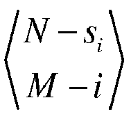


- where i=0, 1, ..., (M-1); N represents the number of subbands of a downlink system, M represents the number of subbands selected by a mobile terminal during reporting a channel quality indicator (CQI), r represents a combined index and


- where


- The method may further comprise, prior to calculating the difference, determining whether the received combined index is greater than or equal to 0 but smaller than or equal to

- The method may further comprise, prior to the eNB receives the combined index, the mobile terminal reports the combined index to the eNB.
- Generating the intermediate value table in advance according to possible values of M and N may specifically comprise:
- plugging the possible values of M and N in


- where h=0, 1, ..., N.
- The method may further comprise, after generating the intermediate value table, taking N, M and i as indexes of the intermediate value table.
- Obtaining each Si may specifically comprise:
- A1: initializing k = 0, then my_r = r, wherein my_r refers to the difference between the received r and the

- B1: searching the first value that is not greater than the current my_r from left to right in the sequences


- C1 : setting


- Obtaining each Si may specifically comprise:
- A2: initializing k = 0, then my_r = r, wherein my_r refers to the difference between the received r and the

- B2: searching the last value that is not greater than the current my_r from right to left in the sequences


- C2 : setting

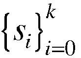


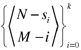
- A device for determining a subband index, comprises: a table generation module, a receiving module and a processing module, wherein
- the table generation module is used for generating and storing an intermediate value table according to possible values of M and N;
- the receiving module is used for receiving r; and
- the processing module is used for calculating a difference between the received r and


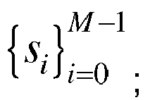
- wherein i=0, 1, ..., (M-1); N represents the number of subbands of a downlink system, M represents the number of subbands selected by a mobile terminal during reporting a channel quality indicator (CQI), r represents a combined index, and Si represents a subband index and

- where


- The table generation module may comprise a first calculation module and a first storage module, wherein
- the first calculation module is used for plugging the possible values of M and N in


- the first storage module is used for storing the obtained sequences as the intermediate value table.
- The processing module may comprise an initialization module, a searching module, a second storage module and a second calculation module, wherein
- the initialization module is used for initializing k = 0, then my_r = r, and sending the result of the initialization to the searching module, wherein my_r refers to the difference between the received r and the

- the searching module is used for searching the first value that is not greater than the current my_r from left to right in the sequences


- the second storage module is used for storing each obtained Sk that constitutes


- the second calculation module is used for setting

- The processing module may further comprise a judging module which is used for triggering the initialization module when the received combined index is greater than or equal to 0 but smaller than or equal to
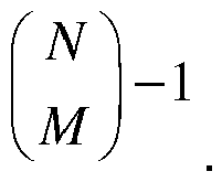
- By calculating the difference between the received combined index and the


-
-
Fig. 1 is a realization flowchart illustrating a method for reporting a subband index according to an embodiment of the present invention; and -
Fig. 2 is a structural schematic diagram illustrating a device for reporting a subband index according to an embodiment of the present invention. - The realization flowchart of a subband index determining method of an embodiment in the present invention is shown in
Fig. 1 , the method comprises the following steps. - Step 101: an eNB obtains sequences

- Wherein the specific generation and storage method is as follows:
- plugging the possible values of M and N in


- where i=0, 1, ..., (M-1), h =0, 1, ..., N; N represents the number of subbands of a downlink system, M represents the number of subbands selected by a mobile terminal, and possible values of M and N can be obtained according to a formula N=downlink system bandwidth/subband size and a correspondence table of the downlink system bandwidth, subband size and M;
- here, N, M and i can be taken as indexes of the intermediate value table to represent each value in the intermediate value table as the value gained by calculating when the values of M, N and i are all the same.
- Step 102: the eNB receives r; wherein r is a combined index;
here, prior tostep 102, further comprising: a mobile terminal reports the combined index to the eNB. - Step 103: the eNB calculates the difference between the received r and the


- The step of obtaining each Si specifically is as follows.
- Step A1: initializing
k = 0, then my_r = r;
wherein my_r refers to the difference between the received r and the
- Step B1: searching the first value that is not greater than the current my_r from left to right in the sequences


wherein the values of N and M in the sequences
- Step C1: setting

here, the set of the obtained subband indexes is represented as


- Here, the particular step of obtaining each Si may also be as follows.
- Step A2: initializing k = 0, then my_r = r, wherein my_r refers to the difference between the received r and the

- Step B2: searching the last value that is not greater than the current my_r from right to left in the sequences


- Step C2 : setting


- Further, the intermediate value table may be released after the subband index determination flow of this time is ended when memory resource is insufficient, and a new intermediate value table is regenerated in the next subband index determination flow.
- The structure of a subband index reporting device in an embodiment of the present invention comprises, as shown in
Fig. 2 , a table generation module, a receiving module and a processing module, wherein
the table generation module is used for obtaining sequences
the receiving module is used for receiving r;
the processing module is used for calculating the difference between the received r and the


wherein i =0, 1, ..., (M-1); N represents the number of subbands of a downlink system, M represents the number of subbands selected by a mobile terminal, r represents a combined index, and
- Wherein, the table generation module comprises a first calculation module and a first storage module, wherein
- the first calculation module is used for plugging the possible values of M and N in


- the first storage module is used for storing the obtained sequences as the intermediate value table.
- Further, the processing module comprises an initialization module, a searching module, a second storage module and a second calculation module, wherein
- the initialization module is used for initializing k = 0, then my_r = r, and sending the result of the initialization to the searching module, wherein my_r refers to the difference between the received r and the

- the searching module is used for searching the first value that is not greater than the current my_r from left to right in the sequences


- the second storage module is used for storing each obtained Sk which constitutes


- the second calculation module is used for setting

- The above-mentioned


- The processing module further comprises a judging module which is used for triggering the initialization module when the received combined index is greater than or equal to 0 but smaller or equal to

- The above are only preferred embodiments of the present invention but not limitation to the protection scope of the present invention.

Claims (11)
- A method for determining a subband index, characterized by:generating and storing an intermediate value table in advance according to possible values of M and Nan Evolved Node B , eNB, receiving r, calculating a difference between the received r and a


 where
where


- The method for determining a subband index according to claim 1, further comprising, prior to calculating the difference, determining whether the received combined index is greater than or equal to 0 but smaller than or equal to

- The method for determining a subband index according to claim 1 or 2, further comprising, prior to the eNB receiving the combined index, the mobile terminal reporting the combined index to the eNB.
- The method for determining a subband index according to claim 1 or 2, wherein generating the intermediate value table in advance according to possible values of M and N specifically comprises:plugging the possible values of M and N in


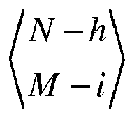
 where h=0, 1, ..., N.
 - The method for determining a subband index according to claim 4, further comprising, after generating the intermediate value table, taking N, M and i as indexes of the intermediate value table.
- The method for determining a subband index according to claim 1, wherein obtaining each Si specifically comprises:A1: initializing k = 0, then my_r = r, wherein my_r refers to the difference between the received r and the
 B1: searching the first value that is not greater than the current my_r from left to right in the sequences
 C1 : setting
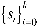

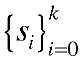

- The method for determining a subband index according to claim 1, wherein obtaining each Si specifically comprises:A2: initializing k = 0, then my_r = r, wherein my_r refers to the difference between the received r and the
 B2: searching the last value that is not greater than the current my_r from right to left in the sequences
 C2 : setting


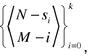
- A device for determining a subband index, characterized in that: the device comprises: a table generation module, a receiving module and a processing module, wherein
the table generation module is used for generating and storing an intermediate value table according to possible values of M and N;
the receiving module is used for receiving r; and
the processing module is used for calculating a difference between the received r and


wherein i=0, 1, ..., (M-1); N represents the number of subbands of a downlink system, M represents the number of subbands selected by a mobile terminal during reporting a channel quality indicator (CQI), r represents a combined index and
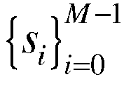
where

- The device for determining a subband index according to claim 8, wherein the table generation module comprises a first calculation module and a first storage module, whereinthe first calculation module is used for plugging the possible values of M and N in


 the first storage module is used for storing the obtained sequences as the intermediate value table.
 - The device for determining a subband index according to claim 8 or 9, wherein the processing module comprises an initialization module, a searching module, a second storage module and a second calculation module, whereinthe initialization module is used for initializing k = 0, then my_r = r, and sending the result of the initialization to the searching module, wherein my_r refers to the difference between the received r and the
 the searching module is used for searching the first value that is not greater than the current my _ r from left to right in the sequences


 the second storage module is used for storing each obtained S k that constitutes
 the second calculation module is used for setting
- The device for determining a subband index according to claim 10, wherein the processing module further comprises a judging module which is used for triggering the initialization module when the received combined index is greater than or equal to 0 but smaller than or equal to

Applications Claiming Priority (2)
| Application Number | Priority Date | Filing Date | Title |
|---|---|---|---|
| CN2009100884266A CN101938812B (en) | 2009-06-29 | 2009-06-29 | Method and device for determining sub-band indexes |
| PCT/CN2010/072533 WO2010145345A1 (en) | 2009-06-29 | 2010-05-07 | Method and device for determining subband index |
Publications (3)
| Publication Number | Publication Date |
|---|---|
| EP2416601A1 EP2416601A1 (en) | 2012-02-08 |
| EP2416601A4 EP2416601A4 (en) | 2015-07-01 |
| EP2416601B1 true EP2416601B1 (en) | 2016-07-06 |
Family
ID=43355784
Family Applications (1)
| Application Number | Title | Priority Date | Filing Date |
|---|---|---|---|
| EP10788741.6A Not-in-force EP2416601B1 (en) | 2009-06-29 | 2010-05-07 | Method and device for determining subband index |
Country Status (5)
| Country | Link |
|---|---|
| US (1) | US8817720B2 (en) |
| EP (1) | EP2416601B1 (en) |
| KR (1) | KR101340320B1 (en) |
| CN (1) | CN101938812B (en) |
| WO (1) | WO2010145345A1 (en) |
Families Citing this family (2)
| Publication number | Priority date | Publication date | Assignee | Title |
|---|---|---|---|---|
| CN105103585B (en) * | 2013-01-14 | 2019-03-08 | 爱立信(中国)通信有限公司 | Resource scheduling method and communication node in wireless communication network |
| EP3753170B1 (en) * | 2018-02-16 | 2021-12-29 | Sony Group Corporation | Telecommunications apparatus, methods and integrated circuit |
Family Cites Families (11)
| Publication number | Priority date | Publication date | Assignee | Title |
|---|---|---|---|---|
| KR100548371B1 (en) * | 2003-07-04 | 2006-02-02 | 엘지전자 주식회사 | Frequency measurement method |
| KR100851624B1 (en) * | 2004-05-06 | 2008-08-13 | 노키아 코포레이션 | Configure Redundancy Versions for Enhanced Uplink Dedicated Channels |
| GB2416959B (en) * | 2004-07-30 | 2009-06-17 | Kyocera Corp | Communications systems |
| KR20060075382A (en) * | 2004-12-28 | 2006-07-04 | 주식회사 팬택 | Mobile communication terminal that provides information on the most recently used menu and most used menus |
| CN1988454B (en) * | 2005-12-23 | 2010-05-12 | 北京三星通信技术研究有限公司 | Method and device for reporting channel quality indication |
| WO2007073121A1 (en) | 2005-12-23 | 2007-06-28 | Samsung Electronics Co., Ltd. | Method and apparatus for channel quality indicator report |
| US8014455B2 (en) * | 2006-03-27 | 2011-09-06 | Qualcomm Incorporated | Feedback of differentially encoded channel state information for multiple-input multiple-output (MIMO) and subband scheduling in a wireless communication system |
| US8699602B2 (en) | 2007-12-13 | 2014-04-15 | Texas Instruments Incorporated | Channel quality report processes, circuits and systems |
| CN101277166A (en) * | 2008-04-03 | 2008-10-01 | 中兴通讯股份有限公司 | A channel quality indication feedback method |
| CN101340697B (en) * | 2008-08-15 | 2012-05-23 | 中兴通讯股份有限公司 | A method for transmitting channel quality indication information feedback period and subframe offset |
| WO2010123241A2 (en) * | 2009-04-22 | 2010-10-28 | Lg Electronics Inc. | Method and apparatus for transmitting ranging channel in wireless communication system |
-
2009
- 2009-06-29 CN CN2009100884266A patent/CN101938812B/en not_active Expired - Fee Related
-
2010
- 2010-05-07 EP EP10788741.6A patent/EP2416601B1/en not_active Not-in-force
- 2010-05-07 WO PCT/CN2010/072533 patent/WO2010145345A1/en not_active Ceased
- 2010-05-07 US US13/258,365 patent/US8817720B2/en not_active Expired - Fee Related
- 2010-05-07 KR KR1020117026242A patent/KR101340320B1/en not_active Expired - Fee Related
Also Published As
| Publication number | Publication date |
|---|---|
| US20120087320A1 (en) | 2012-04-12 |
| KR20120018757A (en) | 2012-03-05 |
| WO2010145345A1 (en) | 2010-12-23 |
| KR101340320B1 (en) | 2013-12-11 |
| CN101938812B (en) | 2013-03-20 |
| CN101938812A (en) | 2011-01-05 |
| EP2416601A4 (en) | 2015-07-01 |
| US8817720B2 (en) | 2014-08-26 |
| EP2416601A1 (en) | 2012-02-08 |
Similar Documents
| Publication | Publication Date | Title |
|---|---|---|
| CN110536315B (en) | Method, device, communication equipment and storage medium for determining CSI report processing time | |
| EP3860017B1 (en) | Information transmission method and devices | |
| EP3113557B1 (en) | Control information enhanced transmission method, user equipment, base station, and communications system | |
| US11930504B2 (en) | Data transmission method and terminal device | |
| CN102255685A (en) | CSI (Channel State Information) feeding back and acquiring method, UE (User Equipment) and base station | |
| US20130215874A1 (en) | Communication method, user equipment and base station | |
| EP2804430B1 (en) | Uplink transmission power determination method and user equipment | |
| CN103037492B (en) | Method for determining uplink transmission power and user equipment | |
| US11178622B2 (en) | Data processing method, terminal, and base station | |
| EP3386234A1 (en) | Channel measurement information feedback method, user equipment and base station | |
| EP3920430A1 (en) | Method and device for determining precoding, method and device for detecting data, storage medium and electronic device | |
| EP3605892B1 (en) | Information transmission method and device, and storage medium | |
| EP3755099A1 (en) | Method for determining resource location, terminal apparatus, and network apparatus | |
| CN107404344B (en) | Communication method, network equipment and terminal equipment | |
| US8817720B2 (en) | Method and device for determining subband index | |
| US9154284B1 (en) | Estimating sounding reference signals for secondary radio-frequency channels | |
| EP3780432A1 (en) | Method for transmitting detection reference signal and terminal device | |
| EP3484054A1 (en) | Rate matching method and device for polar code | |
| KR102213035B1 (en) | Method and transmission apparatus for determining precoding matrix set | |
| US10420076B2 (en) | Resource allocation method and device and information feedback method and device | |
| DE102013112682A1 (en) | Radio communication devices and methods for controlling a radio communication device | |
| CN105897495A (en) | Method for determining KQI and KPI correlation in communication network and equipment | |
| EP4150861B1 (en) | Determining cell upgrade | |
| EP3989609A1 (en) | Method for processing mib message of lte system message, apparatus, base station, and storage medium | |
| EP3627879B1 (en) | Method for detecting link quality and terminal device |
Legal Events
| Date | Code | Title | Description |
|---|---|---|---|
| PUAI | Public reference made under article 153(3) epc to a published international application that has entered the european phase |
Free format text: ORIGINAL CODE: 0009012 |
|
| 17P | Request for examination filed |
Effective date: 20111102 |
|
| AK | Designated contracting states |
Kind code of ref document: A1 Designated state(s): AL AT BE BG CH CY CZ DE DK EE ES FI FR GB GR HR HU IE IS IT LI LT LU LV MC MK MT NL NO PL PT RO SE SI SK SM TR |
|
| DAX | Request for extension of the european patent (deleted) | ||
| RA4 | Supplementary search report drawn up and despatched (corrected) |
Effective date: 20150529 |
|
| RIC1 | Information provided on ipc code assigned before grant |
Ipc: H04W 16/00 20090101AFI20150522BHEP |
|
| GRAP | Despatch of communication of intention to grant a patent |
Free format text: ORIGINAL CODE: EPIDOSNIGR1 |
|
| GRAP | Despatch of communication of intention to grant a patent |
Free format text: ORIGINAL CODE: EPIDOSNIGR1 |
|
| INTG | Intention to grant announced |
Effective date: 20160301 |
|
| INTG | Intention to grant announced |
Effective date: 20160314 |
|
| GRAS | Grant fee paid |
Free format text: ORIGINAL CODE: EPIDOSNIGR3 |
|
| GRAA | (expected) grant |
Free format text: ORIGINAL CODE: 0009210 |
|
| AK | Designated contracting states |
Kind code of ref document: B1 Designated state(s): AL AT BE BG CH CY CZ DE DK EE ES FI FR GB GR HR HU IE IS IT LI LT LU LV MC MK MT NL NO PL PT RO SE SI SK SM TR |
|
| REG | Reference to a national code |
Ref country code: GB Ref legal event code: FG4D |
|
| REG | Reference to a national code |
Ref country code: AT Ref legal event code: REF Ref document number: 811452 Country of ref document: AT Kind code of ref document: T Effective date: 20160715 Ref country code: CH Ref legal event code: EP |
|
| REG | Reference to a national code |
Ref country code: IE Ref legal event code: FG4D |
|
| REG | Reference to a national code |
Ref country code: DE Ref legal event code: R096 Ref document number: 602010034534 Country of ref document: DE |
|
| REG | Reference to a national code |
Ref country code: NL Ref legal event code: MP Effective date: 20160706 |
|
| REG | Reference to a national code |
Ref country code: LT Ref legal event code: MG4D |
|
| REG | Reference to a national code |
Ref country code: AT Ref legal event code: MK05 Ref document number: 811452 Country of ref document: AT Kind code of ref document: T Effective date: 20160706 |
|
| PG25 | Lapsed in a contracting state [announced via postgrant information from national office to epo] |
Ref country code: NO Free format text: LAPSE BECAUSE OF FAILURE TO SUBMIT A TRANSLATION OF THE DESCRIPTION OR TO PAY THE FEE WITHIN THE PRESCRIBED TIME-LIMIT Effective date: 20161006 Ref country code: FI Free format text: LAPSE BECAUSE OF FAILURE TO SUBMIT A TRANSLATION OF THE DESCRIPTION OR TO PAY THE FEE WITHIN THE PRESCRIBED TIME-LIMIT Effective date: 20160706 Ref country code: IT Free format text: LAPSE BECAUSE OF FAILURE TO SUBMIT A TRANSLATION OF THE DESCRIPTION OR TO PAY THE FEE WITHIN THE PRESCRIBED TIME-LIMIT Effective date: 20160706 Ref country code: IS Free format text: LAPSE BECAUSE OF FAILURE TO SUBMIT A TRANSLATION OF THE DESCRIPTION OR TO PAY THE FEE WITHIN THE PRESCRIBED TIME-LIMIT Effective date: 20161106 Ref country code: LT Free format text: LAPSE BECAUSE OF FAILURE TO SUBMIT A TRANSLATION OF THE DESCRIPTION OR TO PAY THE FEE WITHIN THE PRESCRIBED TIME-LIMIT Effective date: 20160706 Ref country code: NL Free format text: LAPSE BECAUSE OF FAILURE TO SUBMIT A TRANSLATION OF THE DESCRIPTION OR TO PAY THE FEE WITHIN THE PRESCRIBED TIME-LIMIT Effective date: 20160706 Ref country code: HR Free format text: LAPSE BECAUSE OF FAILURE TO SUBMIT A TRANSLATION OF THE DESCRIPTION OR TO PAY THE FEE WITHIN THE PRESCRIBED TIME-LIMIT Effective date: 20160706 |
|
| PG25 | Lapsed in a contracting state [announced via postgrant information from national office to epo] |
Ref country code: GR Free format text: LAPSE BECAUSE OF FAILURE TO SUBMIT A TRANSLATION OF THE DESCRIPTION OR TO PAY THE FEE WITHIN THE PRESCRIBED TIME-LIMIT Effective date: 20161007 Ref country code: AT Free format text: LAPSE BECAUSE OF FAILURE TO SUBMIT A TRANSLATION OF THE DESCRIPTION OR TO PAY THE FEE WITHIN THE PRESCRIBED TIME-LIMIT Effective date: 20160706 Ref country code: PT Free format text: LAPSE BECAUSE OF FAILURE TO SUBMIT A TRANSLATION OF THE DESCRIPTION OR TO PAY THE FEE WITHIN THE PRESCRIBED TIME-LIMIT Effective date: 20161107 Ref country code: PL Free format text: LAPSE BECAUSE OF FAILURE TO SUBMIT A TRANSLATION OF THE DESCRIPTION OR TO PAY THE FEE WITHIN THE PRESCRIBED TIME-LIMIT Effective date: 20160706 Ref country code: LV Free format text: LAPSE BECAUSE OF FAILURE TO SUBMIT A TRANSLATION OF THE DESCRIPTION OR TO PAY THE FEE WITHIN THE PRESCRIBED TIME-LIMIT Effective date: 20160706 Ref country code: BE Free format text: LAPSE BECAUSE OF FAILURE TO SUBMIT A TRANSLATION OF THE DESCRIPTION OR TO PAY THE FEE WITHIN THE PRESCRIBED TIME-LIMIT Effective date: 20160706 Ref country code: SE Free format text: LAPSE BECAUSE OF FAILURE TO SUBMIT A TRANSLATION OF THE DESCRIPTION OR TO PAY THE FEE WITHIN THE PRESCRIBED TIME-LIMIT Effective date: 20160706 Ref country code: ES Free format text: LAPSE BECAUSE OF FAILURE TO SUBMIT A TRANSLATION OF THE DESCRIPTION OR TO PAY THE FEE WITHIN THE PRESCRIBED TIME-LIMIT Effective date: 20160706 |
|
| REG | Reference to a national code |
Ref country code: DE Ref legal event code: R097 Ref document number: 602010034534 Country of ref document: DE |
|
| PG25 | Lapsed in a contracting state [announced via postgrant information from national office to epo] |
Ref country code: RO Free format text: LAPSE BECAUSE OF FAILURE TO SUBMIT A TRANSLATION OF THE DESCRIPTION OR TO PAY THE FEE WITHIN THE PRESCRIBED TIME-LIMIT Effective date: 20160706 Ref country code: EE Free format text: LAPSE BECAUSE OF FAILURE TO SUBMIT A TRANSLATION OF THE DESCRIPTION OR TO PAY THE FEE WITHIN THE PRESCRIBED TIME-LIMIT Effective date: 20160706 |
|
| PLBE | No opposition filed within time limit |
Free format text: ORIGINAL CODE: 0009261 |
|
| STAA | Information on the status of an ep patent application or granted ep patent |
Free format text: STATUS: NO OPPOSITION FILED WITHIN TIME LIMIT |
|
| REG | Reference to a national code |
Ref country code: FR Ref legal event code: PLFP Year of fee payment: 8 |
|
| PG25 | Lapsed in a contracting state [announced via postgrant information from national office to epo] |
Ref country code: SK Free format text: LAPSE BECAUSE OF FAILURE TO SUBMIT A TRANSLATION OF THE DESCRIPTION OR TO PAY THE FEE WITHIN THE PRESCRIBED TIME-LIMIT Effective date: 20160706 Ref country code: SM Free format text: LAPSE BECAUSE OF FAILURE TO SUBMIT A TRANSLATION OF THE DESCRIPTION OR TO PAY THE FEE WITHIN THE PRESCRIBED TIME-LIMIT Effective date: 20160706 Ref country code: BG Free format text: LAPSE BECAUSE OF FAILURE TO SUBMIT A TRANSLATION OF THE DESCRIPTION OR TO PAY THE FEE WITHIN THE PRESCRIBED TIME-LIMIT Effective date: 20161006 Ref country code: DK Free format text: LAPSE BECAUSE OF FAILURE TO SUBMIT A TRANSLATION OF THE DESCRIPTION OR TO PAY THE FEE WITHIN THE PRESCRIBED TIME-LIMIT Effective date: 20160706 Ref country code: CZ Free format text: LAPSE BECAUSE OF FAILURE TO SUBMIT A TRANSLATION OF THE DESCRIPTION OR TO PAY THE FEE WITHIN THE PRESCRIBED TIME-LIMIT Effective date: 20160706 |
|
| 26N | No opposition filed |
Effective date: 20170407 |
|
| PG25 | Lapsed in a contracting state [announced via postgrant information from national office to epo] |
Ref country code: SI Free format text: LAPSE BECAUSE OF FAILURE TO SUBMIT A TRANSLATION OF THE DESCRIPTION OR TO PAY THE FEE WITHIN THE PRESCRIBED TIME-LIMIT Effective date: 20160706 Ref country code: LU Free format text: LAPSE BECAUSE OF NON-PAYMENT OF DUE FEES Effective date: 20170531 |
|
| REG | Reference to a national code |
Ref country code: CH Ref legal event code: PL |
|
| PG25 | Lapsed in a contracting state [announced via postgrant information from national office to epo] |
Ref country code: MC Free format text: LAPSE BECAUSE OF FAILURE TO SUBMIT A TRANSLATION OF THE DESCRIPTION OR TO PAY THE FEE WITHIN THE PRESCRIBED TIME-LIMIT Effective date: 20160706 |
|
| REG | Reference to a national code |
Ref country code: IE Ref legal event code: MM4A |
|
| PG25 | Lapsed in a contracting state [announced via postgrant information from national office to epo] |
Ref country code: LI Free format text: LAPSE BECAUSE OF NON-PAYMENT OF DUE FEES Effective date: 20170531 Ref country code: CH Free format text: LAPSE BECAUSE OF NON-PAYMENT OF DUE FEES Effective date: 20170531 |
|
| PG25 | Lapsed in a contracting state [announced via postgrant information from national office to epo] |
Ref country code: LU Free format text: LAPSE BECAUSE OF NON-PAYMENT OF DUE FEES Effective date: 20170507 |
|
| PG25 | Lapsed in a contracting state [announced via postgrant information from national office to epo] |
Ref country code: IE Free format text: LAPSE BECAUSE OF NON-PAYMENT OF DUE FEES Effective date: 20170507 |
|
| REG | Reference to a national code |
Ref country code: FR Ref legal event code: PLFP Year of fee payment: 9 |
|
| PG25 | Lapsed in a contracting state [announced via postgrant information from national office to epo] |
Ref country code: MT Free format text: LAPSE BECAUSE OF NON-PAYMENT OF DUE FEES Effective date: 20170507 |
|
| PG25 | Lapsed in a contracting state [announced via postgrant information from national office to epo] |
Ref country code: AL Free format text: LAPSE BECAUSE OF FAILURE TO SUBMIT A TRANSLATION OF THE DESCRIPTION OR TO PAY THE FEE WITHIN THE PRESCRIBED TIME-LIMIT Effective date: 20160706 |
|
| PG25 | Lapsed in a contracting state [announced via postgrant information from national office to epo] |
Ref country code: HU Free format text: LAPSE BECAUSE OF FAILURE TO SUBMIT A TRANSLATION OF THE DESCRIPTION OR TO PAY THE FEE WITHIN THE PRESCRIBED TIME-LIMIT; INVALID AB INITIO Effective date: 20100507 |
|
| PG25 | Lapsed in a contracting state [announced via postgrant information from national office to epo] |
Ref country code: CY Free format text: LAPSE BECAUSE OF NON-PAYMENT OF DUE FEES Effective date: 20160706 |
|
| PG25 | Lapsed in a contracting state [announced via postgrant information from national office to epo] |
Ref country code: MK Free format text: LAPSE BECAUSE OF FAILURE TO SUBMIT A TRANSLATION OF THE DESCRIPTION OR TO PAY THE FEE WITHIN THE PRESCRIBED TIME-LIMIT Effective date: 20160706 |
|
| PG25 | Lapsed in a contracting state [announced via postgrant information from national office to epo] |
Ref country code: TR Free format text: LAPSE BECAUSE OF FAILURE TO SUBMIT A TRANSLATION OF THE DESCRIPTION OR TO PAY THE FEE WITHIN THE PRESCRIBED TIME-LIMIT Effective date: 20160706 |
|
| PGFP | Annual fee paid to national office [announced via postgrant information from national office to epo] |
Ref country code: FR Payment date: 20201028 Year of fee payment: 11 Ref country code: DE Payment date: 20201031 Year of fee payment: 11 Ref country code: GB Payment date: 20201028 Year of fee payment: 11 |
|
| REG | Reference to a national code |
Ref country code: DE Ref legal event code: R119 Ref document number: 602010034534 Country of ref document: DE |
|
| GBPC | Gb: european patent ceased through non-payment of renewal fee |
Effective date: 20210507 |
|
| PG25 | Lapsed in a contracting state [announced via postgrant information from national office to epo] |
Ref country code: GB Free format text: LAPSE BECAUSE OF NON-PAYMENT OF DUE FEES Effective date: 20210507 Ref country code: DE Free format text: LAPSE BECAUSE OF NON-PAYMENT OF DUE FEES Effective date: 20211201 |
|
| PG25 | Lapsed in a contracting state [announced via postgrant information from national office to epo] |
Ref country code: FR Free format text: LAPSE BECAUSE OF NON-PAYMENT OF DUE FEES Effective date: 20210531 |