EP2416466A2 - HVDC connection of wind turbine - Google Patents
HVDC connection of wind turbine Download PDFInfo
- Publication number
- EP2416466A2 EP2416466A2 EP11175150A EP11175150A EP2416466A2 EP 2416466 A2 EP2416466 A2 EP 2416466A2 EP 11175150 A EP11175150 A EP 11175150A EP 11175150 A EP11175150 A EP 11175150A EP 2416466 A2 EP2416466 A2 EP 2416466A2
- Authority
- EP
- European Patent Office
- Prior art keywords
- voltage
- converter
- output
- level
- hvdc
- Prior art date
- Legal status (The legal status is an assumption and is not a legal conclusion. Google has not performed a legal analysis and makes no representation as to the accuracy of the status listed.)
- Ceased
Links
Images


Classifications
-
- H—ELECTRICITY
- H02—GENERATION; CONVERSION OR DISTRIBUTION OF ELECTRIC POWER
- H02J—ELECTRIC POWER NETWORKS; CIRCUIT ARRANGEMENTS OR SYSTEMS FOR SUPPLYING OR DISTRIBUTING ELECTRIC POWER; SYSTEMS FOR STORING ELECTRIC ENERGY
- H02J3/00—Circuit arrangements for AC mains or AC distribution networks
- H02J3/36—Arrangements for transfer of electric power between AC networks via high-voltage DC [HVDC] links; Arrangements for transfer of electric power between generators and networks via HVDC links
-
- H—ELECTRICITY
- H02—GENERATION; CONVERSION OR DISTRIBUTION OF ELECTRIC POWER
- H02J—ELECTRIC POWER NETWORKS; CIRCUIT ARRANGEMENTS OR SYSTEMS FOR SUPPLYING OR DISTRIBUTING ELECTRIC POWER; SYSTEMS FOR STORING ELECTRIC ENERGY
- H02J3/00—Circuit arrangements for AC mains or AC distribution networks
- H02J3/38—Arrangements for feeding a single network from two or more generators or sources in parallel; Arrangements for feeding already energised networks from additional generators or sources in parallel
- H02J3/381—Dispersed generators
-
- H—ELECTRICITY
- H02—GENERATION; CONVERSION OR DISTRIBUTION OF ELECTRIC POWER
- H02J—ELECTRIC POWER NETWORKS; CIRCUIT ARRANGEMENTS OR SYSTEMS FOR SUPPLYING OR DISTRIBUTING ELECTRIC POWER; SYSTEMS FOR STORING ELECTRIC ENERGY
- H02J2101/00—Supply or distribution of decentralised, dispersed or local electric power generation
- H02J2101/20—Dispersed power generation using renewable energy sources
- H02J2101/28—Wind energy
-
- Y—GENERAL TAGGING OF NEW TECHNOLOGICAL DEVELOPMENTS; GENERAL TAGGING OF CROSS-SECTIONAL TECHNOLOGIES SPANNING OVER SEVERAL SECTIONS OF THE IPC; TECHNICAL SUBJECTS COVERED BY FORMER USPC CROSS-REFERENCE ART COLLECTIONS [XRACs] AND DIGESTS
- Y02—TECHNOLOGIES OR APPLICATIONS FOR MITIGATION OR ADAPTATION AGAINST CLIMATE CHANGE
- Y02E—REDUCTION OF GREENHOUSE GAS [GHG] EMISSIONS, RELATED TO ENERGY GENERATION, TRANSMISSION OR DISTRIBUTION
- Y02E10/00—Energy generation through renewable energy sources
- Y02E10/70—Wind energy
- Y02E10/76—Power conversion electric or electronic aspects
-
- Y—GENERAL TAGGING OF NEW TECHNOLOGICAL DEVELOPMENTS; GENERAL TAGGING OF CROSS-SECTIONAL TECHNOLOGIES SPANNING OVER SEVERAL SECTIONS OF THE IPC; TECHNICAL SUBJECTS COVERED BY FORMER USPC CROSS-REFERENCE ART COLLECTIONS [XRACs] AND DIGESTS
- Y02—TECHNOLOGIES OR APPLICATIONS FOR MITIGATION OR ADAPTATION AGAINST CLIMATE CHANGE
- Y02E—REDUCTION OF GREENHOUSE GAS [GHG] EMISSIONS, RELATED TO ENERGY GENERATION, TRANSMISSION OR DISTRIBUTION
- Y02E60/00—Enabling technologies; Technologies with a potential or indirect contribution to GHG emissions mitigation
- Y02E60/60—Arrangements for transfer of electric power between AC networks or generators via a high voltage DC link [HVCD]
Definitions
- the present invention relates generally to the field of wind generators, and, more particularly, to methods and systems to allow for improved power transmission from wind generator sites through creation of on site HVDC transmission level voltage.
- FIG. 1 shows a typical such grid connected wind power generating system 10.
- the system includes a wind generator 12, a generator side converter 14 and a grid side converter 16.
- the system further includes a grid side controller 18, a generator side controller 20 and a power grid 22.
- a direct current (DC) link 28 connects the generator side converter 14 and the grid side converter 16.
- the generator side converter 14 converts alternating current (AC) power generated by the wind generator 12 into DC power.
- the grid side converter 18 then converts the DC power to AC power at a frequency compatible with the power grid 22.
- the combination of the grid side controller 18 and grid side converter 16 functions as a current source for the grid 22.
- the grid side controller 18 controls the phase and amplitude of the output current of grid side converter 16.
- the generator side controller 20 generates switching signals for the generator side converter 14.
- a turbine controller 38 provides a torque reference T to the generator side controller 20 based on wind velocity or rotor speed of the wind turbine.
- the turbine controller 38 generates the torque reference such that maximum energy is captured from the wind using, in part, Maximum Power Point Tracking (MPPT) circuitry.
- MPPT Maximum Power Point Tracking
- One exemplary embodiment of the present disclosure is directed to a method for high voltage direct current (HVDC) connection of wind turbines for power transmission independently of an AC grid.
- the wind driven generator is configured to produce a variable frequency AC voltage output.
- the method provides for increasing the generated voltage level sufficiently to provide power to a HVDC transmission line.
- the method also provides for converting the voltage to DC and applying the voltage to a HVDC transmission line.
- the voltage level is first increased from one AC voltage level to a higher AC voltage level and then rectified before applying the voltage to the HVDC transmission line.
- the voltage from the wind driven generator is converted to a DC voltage by an AC-DC converter and then boosted to a higher level by a high-voltage DC-DC converter before being applied to the HVDC transmission line.
- a matrix converter is used to convert the voltage from one AC frequency to a higher AC frequency.
- the higher frequency level is further applied to a step up transformer to increase the voltage level.
- the stepped high frequency voltage may then be rectified before being applied to a HVDC transmission line.
- no conversion to a nominal AC distribution frequency eg., 50 or 60 Hz is required.
- Another exemplary embodiment of the present disclosure is directed to apparatus for connection of a variable frequency AC producing wind turbine generator for power transmission to a HVDC transmission line independently of an AC grid.
- the apparatus includes a voltage level increaser and an AC-DC converter interconnected so as to receive a variable AC output from the wind turbine generator and apply HVDC power directly to an HVDC transmission line.
- the voltage level increaser is a matrix converter and step up transformer configured to convert the AC voltage from the wind driven turbine generator to a higher-level AC voltage and the AC-DC converter is a rectifier coupled to the output of the matrix converter.
- the voltage level increaser is a high-voltage DC-DC converter circuit that receives a DC input from an AC-DC converter.
- the AC input from the AC-DC converter is supplied from the wind driven turbine generator.
- the HVDC output of the high-voltage DC-DC converter may be connected directly to the HVDC transmission line.
- existing turbines generally are designed to connect to an AC grid with a nominal voltage between 10k V AC and 35k V AC .
- the grid side converter 16 and transformer 50 ( FIG. 1 ) must operate at the same frequency as the grid, typically 50 Hz or 60 Hz.
- the AC grid itself may correspond to many miles of cables and additional transformers.
- the present technology eliminates the need for a local AC network and HVDC converter station.
- the present technology also removes the restriction of operating the inverters at the grid frequency, it is possible to reduce the cost, size and weight of the magnetic components, particularly the inverter transformer, by operating at a higher frequency. This has the potential to yield a lower overall cost of the complete system including power transmission to a load center.
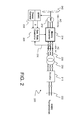
- FIG. 2 there is illustrated a diagrammatical representation of an AC-AC-DC conversion system 200 in accordance with a first exemplary embodiment of the present subject matter.
- the embodiment illustrated in FIG. 2 includes a similar wind turbine 242, wind driven generator 212, and a generator side controller 220 receiving controlling signals from power controller 238.
- a matrix converter 214 is provided that is configured to directly convert the nominal 50 to 110 Hz AC output of generator 212 directly to a higher frequency AC voltage and supply such AC voltage to bus 228.
- the higher frequency AC voltage may be provided at about 400 Hz and the matrix converter may correspond to one as described, for example, in " Novel Three-Phase AC- AC Sparse Matrix Converters" by Kolar et al.; Power Electronics, IEEE Transactions on Volume 22, Issue 5, Sept. 2007 pages 1649-1661 .
- a matrix convert has some operation similarities to the combined operation of a generator side converter and grid side converter such as converters 14 and 16 ( FIG. 1 ) but lacks an energy storage element such as the capacitor bridging DC bus 28 of FIG. 1 .
- the higher frequency AC voltage applied from matrix converter 214 to bus 228 may then be applied to transformer 250 that, because of the higher operating frequency, may be constructed at reduced cost at least in part on the basis of required magnetic components.
- Active power control may be achieved by adjusting the AC voltage at bus 228 by supplying a signal via line 230 to generator side controller 220 representative of the bus 228 voltage.
- FIG. 2 illustrates a three-phase matrix converter 214 supplying three-phase AC at approximately 400 Hz
- multi-phase AC may be generated at about 400 Hz or other appropriate frequencies.
- a rectifier 210 is provided to receive the stepped up AC output of transformer 250 and supply rectified current to HVDC bus 222.
- transformer 250 may also be configured with multiple windings and/or with multiple windings with series connected rectifiers to correspond to illustrated rectifier 210.
- the three-phase AC voltage at bus 228 from matrix converter 214 may be in the range of 1400 V RMS at a frequency of about 400 Hz. As previously noted, the amplitude of this voltage is adjusted to regulate the real power flow from the generator.
- the voltage at HVDC bus 222 typically may be on the order of 50k V dc .
- rectifier 210 may correspond to a simple diode bridge, or a phase-controlled thyristors bridge while the output of transformer 250 will typically be above 50k V ac so that power will flow from transformer 250 to HVDC grid.
- FIG. 3 there is illustrated a diagrammatical representation of an AC-DC-DC conversion system 300 in accordance with a second exemplary embodiment of the present subject matter.
- Conversion system 300 is similar in some aspects to conversion system 10 ( FIG. 1 ) in that there is provided a turbine 342 driving a generator 312 which supplies variable frequency AC power to a generator side converter 314.
- the supplied power from generator 312 may be AC in the range of 50 to 110 Hz.
- a controller 338 supplies control signals to generator side converter 314 in a manner similar to that of controller 38 to generator side converter 20 as described previously with respect to FIG. 1 .
- the embodiment of FIG. 3 provides a DC bus 328 with included storage element (generally a capacitor - not separately labeled) coupled there across.
- grid side controller 318 monitors the voltage across bus 328 and supplies a control signal to high-voltage DC-DC converter 316.
- High-voltage DC-DC converter 316 in turn receives the relatively lower DC voltage from bus 328 and raises it directly to a level appropriate for application to HVDC bus 322.
- high-voltage DC-DC converters are known in the art and may correspond to devices such as disclosed in "High-Voltage DC-DC Converter for New-Generation Electric Locomotives" G. S. Zinov'ev, N. N. Lopatkin, and H. Vais.
- active power control is provided by adjusting high-voltage DC-DC converter 316's operating frequency and/or duty cycle.
- high-voltage DC-DC converter 316 may include a voltage multiplier to assist in obtaining an appropriate HVDC level for coupling to the HVDC bus 322 for transmission to the DC grid.
- the DC voltage available on DC bus 328 for application to high-voltage DC-DC converter 316 may be on the order of 2500 V DC while the output of high-voltage DC-DC converter 316 and optionally included voltage multiplier is of a proper level to be applied to the nominal 50k V DC grid without employing a step up transformer.
- FIG. 4 there is illustrated a diagrammatical representation of an AC-DC-DC conversion system 400 in accordance with a third exemplary embodiment of the present subject matter.
- Conversion system 400 is similar in most aspects to conversion system 300 ( FIG. 3 ) in that there is provided a turbine 442 driving a generator 412 which supplies variable frequency AC power to a generator side converter 414.
- the supplied power from generator 412 may be AC in the range of 50 to 110 Hz.
- controller 438 supplies control signals to grid side controller 418 as opposed to that of controller 338 to generator side controller 320 as described previously with respect to FIG. 3 .
- controller 438 provides a DC bus 428 with included storage element (generally a capacitor - not separately labeled) coupled there across.
- grid side controller 418 receives a torque or power signal from MPPT/power control 438 and supplies a control signal to high-voltage DC-DC converter 416.
- High-voltage DC-DC converter 416 in turn receives the relatively lower DC voltage from bus 428 and raises it directly to a level appropriate for application to HVDC bus 422.
Landscapes
- Engineering & Computer Science (AREA)
- Power Engineering (AREA)
- Control Of Eletrric Generators (AREA)
Abstract
Description
- The present invention relates generally to the field of wind generators, and, more particularly, to methods and systems to allow for improved power transmission from wind generator sites through creation of on site HVDC transmission level voltage.
- Existing wind turbines include an inverter that regulates ac voltage in synchronism with the AC grid, connected via a step-up transformer operating at the grid frequency.
FIG. 1 shows a typical such grid connected windpower generating system 10. The system includes awind generator 12, agenerator side converter 14 and agrid side converter 16. The system further includes agrid side controller 18, agenerator side controller 20 and apower grid 22. A direct current (DC)link 28 connects thegenerator side converter 14 and thegrid side converter 16. Thegenerator side converter 14 converts alternating current (AC) power generated by thewind generator 12 into DC power. Thegrid side converter 18 then converts the DC power to AC power at a frequency compatible with thepower grid 22. - The combination of the
grid side controller 18 andgrid side converter 16 functions as a current source for thegrid 22. In other words, thegrid side controller 18 controls the phase and amplitude of the output current ofgrid side converter 16. Thegenerator side controller 20 generates switching signals for thegenerator side converter 14. In some embodiments, aturbine controller 38 provides a torque reference T to thegenerator side controller 20 based on wind velocity or rotor speed of the wind turbine. Theturbine controller 38 generates the torque reference such that maximum energy is captured from the wind using, in part, Maximum Power Point Tracking (MPPT) circuitry. Active power control of the windpower generating system 10 ofFIG. 1 maintains the output current of thewind turbine 42 by adjusting the phase angle of the AC voltage applied to thegrid 22 viatransformer 50. - Recently it has become advantageous in certain instances to convert the output previously applied to the
AC distribution grid 22 to DC for transmission from, for example, offshore wind farms via subsea cables. In exemplary configurations, the need to convert the normally generated AC voltage to DC for transmission is met by coupling rectifiers to the output side oftransformer 50 at the generator site and coupling the rectifier output to a DC transmission line. The addition of further components at the generator site, particularly in the case of offshore installations, however, presents additional challenges at least in view of the additional space and cost required for such devices. - Thus, there is a need for a method and system to reduce the number of conversion components and costs required to produce direct current at a suitable level for application to a DC transmission line.
- Various aspects and advantages of the invention will be set forth in part in the following description, or may be clear from the description, or may be learned through practice of the invention.
- One exemplary embodiment of the present disclosure is directed to a method for high voltage direct current (HVDC) connection of wind turbines for power transmission independently of an AC grid. The wind driven generator is configured to produce a variable frequency AC voltage output. The method provides for increasing the generated voltage level sufficiently to provide power to a HVDC transmission line.
- The method also provides for converting the voltage to DC and applying the voltage to a HVDC transmission line. In some embodiments the voltage level is first increased from one AC voltage level to a higher AC voltage level and then rectified before applying the voltage to the HVDC transmission line.
- In other embodiments, the voltage from the wind driven generator is converted to a DC voltage by an AC-DC converter and then boosted to a higher level by a high-voltage DC-DC converter before being applied to the HVDC transmission line.
- In certain embodiments a matrix converter is used to convert the voltage from one AC frequency to a higher AC frequency. In certain of these embodiments, the higher frequency level is further applied to a step up transformer to increase the voltage level. The stepped high frequency voltage may then be rectified before being applied to a HVDC transmission line. In each exemplary embodiment, no conversion to a nominal AC distribution frequency (eg., 50 or 60 Hz) is required.
- Another exemplary embodiment of the present disclosure is directed to apparatus for connection of a variable frequency AC producing wind turbine generator for power transmission to a HVDC transmission line independently of an AC grid. The apparatus includes a voltage level increaser and an AC-DC converter interconnected so as to receive a variable AC output from the wind turbine generator and apply HVDC power directly to an HVDC transmission line.
- In some embodiments the voltage level increaser is a matrix converter and step up transformer configured to convert the AC voltage from the wind driven turbine generator to a higher-level AC voltage and the AC-DC converter is a rectifier coupled to the output of the matrix converter.
- In other embodiments the voltage level increaser is a high-voltage DC-DC converter circuit that receives a DC input from an AC-DC converter. The AC input from the AC-DC converter is supplied from the wind driven turbine generator. In embodiments employing the high-voltage DC-DC converter, the HVDC output of the high-voltage DC-DC converter may be connected directly to the HVDC transmission line.
- Variations and modifications can be made to these exemplary embodiments of the present disclosure.
- Various features, aspects and advantages of the present invention will become better understood with reference to the following description and appended claims. The accompanying drawings, which are incorporated in and constitute a part of this specification, illustrate embodiments of the invention and, together with the description, serve to explain the principles of the invention. In the drawings:
-
FIG. 1 is a diagrammatical representation of a conventional wind power generating system connected to a power grid; -
FIG. 2 is a diagrammatical representation of an AC-AC-DC conversion system in accordance with a first exemplary embodiment of the present subject matter; -
FIG. 3 is a diagrammatical representation of an AC-DC-DC conversion system in accordance with a second exemplary embodiment of the present subject matter; and -
FIG. 4 is a diagrammatical representation of an AC-DC-DC conversion system in accordance with a third exemplary embodiment of the present subject matter. - Reference now will be made in detail to embodiments of the invention, one or more examples of which are illustrated in the drawings. Each example is provided by way of explanation of the invention, not limitation of the invention. In fact, it will be apparent to those skilled in the art that various modifications and variations can be made in the present invention without departing from the scope or spirit of the invention. For instance, features illustrated or described as part of one embodiment, can be used with another embodiment to yield a still further embodiment. Thus, it is intended that the present invention encompass such modifications and variations as come within the scope of the appended claims and their equivalents.
- With reference now to the present subject matter, it is noted that existing turbines generally are designed to connect to an AC grid with a nominal voltage between 10k VAC and 35k VAC. Of course the
grid side converter 16 and transformer 50 (FIG. 1 ) must operate at the same frequency as the grid, typically 50 Hz or 60 Hz. The AC grid itself may correspond to many miles of cables and additional transformers. - For long distance cable transmission of wind-generated power, e.g. greater than 50 miles, the cost of the transmission system is lower if HVDC cables are used; however there is a challenge in connecting the wind turbines to the HVDC cables. Existing methods involve creating an AC grid at the remote location, then providing one HVDC converter station and line for the long portion of the transmission.
- In accordance with the present subject matter, however, the present technology eliminates the need for a local AC network and HVDC converter station. In addition, because the present technology also removes the restriction of operating the inverters at the grid frequency, it is possible to reduce the cost, size and weight of the magnetic components, particularly the inverter transformer, by operating at a higher frequency. This has the potential to yield a lower overall cost of the complete system including power transmission to a load center.
- With reference now to
FIG. 2 , there is illustrated a diagrammatical representation of an AC-AC-DC conversion system 200 in accordance with a first exemplary embodiment of the present subject matter. It will be apparent from a comparison withFIG. 1 that the embodiment illustrated inFIG. 2 includes asimilar wind turbine 242, wind drivengenerator 212, and agenerator side controller 220 receiving controlling signals frompower controller 238. In this embodiment of the present subject matter, however, amatrix converter 214 is provided that is configured to directly convert the nominal 50 to 110 Hz AC output ofgenerator 212 directly to a higher frequency AC voltage and supply such AC voltage tobus 228. - In an exemplary configuration, the higher frequency AC voltage may be provided at about 400 Hz and the matrix converter may correspond to one as described, for example, in "Novel Three-Phase AC- AC Sparse Matrix Converters" by Kolar et al.; Power Electronics, IEEE Transactions on . As is understood by those of ordinary skill in the art, a matrix convert has some operation similarities to the combined operation of a generator side converter and grid side converter such as
converters 14 and 16 (FIG. 1 ) but lacks an energy storage element such as the capacitor bridgingDC bus 28 ofFIG. 1 . - The higher frequency AC voltage applied from
matrix converter 214 tobus 228 may then be applied to transformer 250 that, because of the higher operating frequency, may be constructed at reduced cost at least in part on the basis of required magnetic components. Active power control may be achieved by adjusting the AC voltage atbus 228 by supplying a signal vialine 230 togenerator side controller 220 representative of thebus 228 voltage. - It should be appreciated that while
FIG. 2 illustrates a three-phase matrix converter 214 supplying three-phase AC at approximately 400 Hz, other configurations are possible and anticipated by the present subject matter. For example multi-phase AC may be generated at about 400 Hz or other appropriate frequencies. - Further with respect to
FIG. 2 , it will be seen that arectifier 210 is provided to receive the stepped up AC output oftransformer 250 and supply rectified current toHVDC bus 222. In this regard,transformer 250 may also be configured with multiple windings and/or with multiple windings with series connected rectifiers to correspond to illustratedrectifier 210. - In an exemplary configuration as described with respect to
FIG. 2 , the three-phase AC voltage atbus 228 frommatrix converter 214 may be in the range of 1400 VRMS at a frequency of about 400 Hz. As previously noted, the amplitude of this voltage is adjusted to regulate the real power flow from the generator. The voltage atHVDC bus 222 typically may be on the order of 50k Vdc. In exemplary embodiments,rectifier 210 may correspond to a simple diode bridge, or a phase-controlled thyristors bridge while the output oftransformer 250 will typically be above 50k Vac so that power will flow fromtransformer 250 to HVDC grid. - With respect now to
FIG. 3 there is illustrated a diagrammatical representation of an AC-DC-DC conversion system 300 in accordance with a second exemplary embodiment of the present subject matter.Conversion system 300 is similar in some aspects to conversion system 10 (FIG. 1 ) in that there is provided aturbine 342 driving agenerator 312 which supplies variable frequency AC power to agenerator side converter 314. The supplied power fromgenerator 312 may be AC in the range of 50 to 110 Hz. - A
controller 338 supplies control signals togenerator side converter 314 in a manner similar to that ofcontroller 38 togenerator side converter 20 as described previously with respect toFIG. 1 . Similarly also as with respect toFIG. 1 , the embodiment ofFIG. 3 provides aDC bus 328 with included storage element (generally a capacitor - not separately labeled) coupled there across. - Further, in similar fashion to
converter 10 ofFIG. 1 , is provided agrid side controller 318 but in this instancegrid side controller 318 monitors the voltage acrossbus 328 and supplies a control signal to high-voltage DC-DC converter 316. High-voltage DC-DC converter 316 in turn receives the relatively lower DC voltage frombus 328 and raises it directly to a level appropriate for application toHVDC bus 322. high-voltage DC-DC converters are known in the art and may correspond to devices such as disclosed in "High-Voltage DC-DC Converter for New-Generation Electric Locomotives" G. S. Zinov'ev, N. N. Lopatkin, and H. Vais. - In this embodiment of the present subject matter, active power control is provided by adjusting high-voltage DC-
DC converter 316's operating frequency and/or duty cycle. In some embodiments, high-voltage DC-DC converter 316 may include a voltage multiplier to assist in obtaining an appropriate HVDC level for coupling to theHVDC bus 322 for transmission to the DC grid. In an exemplary configuration the DC voltage available onDC bus 328 for application to high-voltage DC-DC converter 316 may be on the order of 2500 VDC while the output of high-voltage DC-DC converter 316 and optionally included voltage multiplier is of a proper level to be applied to the nominal 50k VDC grid without employing a step up transformer. - With respect now to
FIG. 4 there is illustrated a diagrammatical representation of an AC-DC-DC conversion system 400 in accordance with a third exemplary embodiment of the present subject matter.Conversion system 400 is similar in most aspects to conversion system 300 (FIG. 3 ) in that there is provided aturbine 442 driving agenerator 412 which supplies variable frequency AC power to agenerator side converter 414. The supplied power fromgenerator 412 may be AC in the range of 50 to 110 Hz. - In accordance with the embodiment of
FIG. 4 ,controller 438 supplies control signals togrid side controller 418 as opposed to that ofcontroller 338 togenerator side controller 320 as described previously with respect toFIG. 3 . Similarly also as with respect toFIG. 3 , the embodiment ofFIG. 4 provides aDC bus 428 with included storage element (generally a capacitor - not separately labeled) coupled there across. - Further, in similar fashion to
converter 300 ofFIG. 3 , there is provided agrid side controller 418 but in this instancegrid side controller 418 receives a torque or power signal from MPPT/power control 438 and supplies a control signal to high-voltage DC-DC converter 416. High-voltage DC-DC converter 416 in turn receives the relatively lower DC voltage frombus 428 and raises it directly to a level appropriate for application toHVDC bus 422. - This written description uses examples to disclose the invention, including the preferred mode, and also to enable any person skilled in the art to practice the invention, including making and using any devices or systems and performing any incorporated methods. The patentable scope of the invention is defined by the claims, and may include other examples that occur to those skilled in the art. Such other examples are intended to be within the scope of the claims if they include structural elements that do not differ from the literal language of the claims, or if they include equivalent structural elements with insubstantial differences from the literal languages of the claims.
Claims (15)
- A method for high voltage direct current (HVDC) connection of wind turbines for power transmission independently of an AC grid, comprising:providing a wind driven generator (12) configured to produce a variable frequency AC voltage output;increasing the voltage level sufficiently to provide power to a HVDC transmission line;converting the voltage to DC; andapplying the voltage to a HVDC transmission line.
- The method of claim 1, wherein increasing the voltage level comprises:converting the variable frequency AC voltage from the wind generator (12) to a higher frequency AC voltage; andincreasing the voltage level of the higher frequency AC voltage.
- The method of any preceding claim, wherein increasing the voltage level comprises:converting the variable frequency AC voltage to a higher level DC voltage;
and,boosting the higher level DC voltage sufficiently to provide power to a HVDC transmission line. - The method of any preceding claim, wherein converting the voltage to DC comprises:providing a matrix converter (214) having an input and an output;coupling the input of the matrix converter (214) to the variable frequency output of the wind driven generator (12); andcoupling the output of the matrix converter to a rectifier (210).
- The method of claim 4, further comprising, coupling the output of the matrix converter (214) to the rectifier (210) by way of a step up transformer (250).
- The method of claim 4 or claim 5, wherein the output of the matrix converter (214) is an AC voltage at about 400 Hz.
- The method of any preceding claim, wherein converting the voltage to DC comprises, coupling the output of the wind driven generator (12) to an AC-DC converter.
- The method of claim 7, wherein increasing the voltage level comprises, coupling the DC output of the AC-DC converter to a high-voltage DC-DC converter (316).
- The method of claim 8, further comprising, providing an active power control signal to the high-voltage DC-DC converter (316) responsive to the DC output of the AC-DC converter.
- The method of any preceding claim, further comprising, providing an active power control signal to the generator side converter (14) responsive to the DC output of the AC-DC converter.
- An apparatus for connection of a variable frequency AC producing wind turbine generator (12) for power transmission to a HVDC transmission line independently of an AC grid, comprising:a voltage level increaser;an AC-DC converter; andcoupling means configured to couple a variable AC output from the wind turbine generator (12) to the voltage level increaser and the AC-DC converter directly to an HVDC transmission line.
- The apparatus as in claim 11, wherein the voltage level increaser is a matrix converter (214) and step up transformer (250) configured to convert a first AC voltage to a higher-level AC voltage.
- The apparatus as in claim 11 or claim 12, wherein the higher level AC voltage is at a higher frequency than the first AC voltage.
- The apparatus as in any of claims 11 to 13, wherein the AC input voltage to the AC-DC converter is the variable frequency AC produced from the wind turbine generator (12).
- The apparatus as in any of claims 11 to 14, wherein the voltage level increaser is a high-voltage DC-DC converter (316) configured to receive a DC voltage from the AC-DC converter and to produce a HVDC for connection to the HVDC transmission line.
Applications Claiming Priority (1)
| Application Number | Priority Date | Filing Date | Title |
|---|---|---|---|
| US12/850,803 US8018083B2 (en) | 2010-08-05 | 2010-08-05 | HVDC connection of wind turbine |
Publications (2)
| Publication Number | Publication Date |
|---|---|
| EP2416466A2 true EP2416466A2 (en) | 2012-02-08 |
| EP2416466A3 EP2416466A3 (en) | 2017-01-11 |
Family
ID=44142718
Family Applications (1)
| Application Number | Title | Priority Date | Filing Date |
|---|---|---|---|
| EP11175150.9A Ceased EP2416466A3 (en) | 2010-08-05 | 2011-07-25 | HVDC connection of wind turbine |
Country Status (3)
| Country | Link |
|---|---|
| US (1) | US8018083B2 (en) |
| EP (1) | EP2416466A3 (en) |
| CN (1) | CN102377193A (en) |
Families Citing this family (38)
| Publication number | Priority date | Publication date | Assignee | Title |
|---|---|---|---|---|
| CN101401294B (en) * | 2006-03-17 | 2013-04-17 | 英捷电力技术有限公司 | Variable speed wind turbine having an exciter machine and a power converter not connected to the grid |
| US7425771B2 (en) * | 2006-03-17 | 2008-09-16 | Ingeteam S.A. | Variable speed wind turbine having an exciter machine and a power converter not connected to the grid |
| BR112012027571A2 (en) * | 2010-04-26 | 2016-08-02 | Univ Kingston | Maximum power point tracking method, maximum power point follower, micro inverter for a power generator and power generation system |
| EP2621071A4 (en) * | 2010-09-22 | 2017-05-17 | Toshiba Mitsubishi-Electric Industrial Systems Corporation | Power conversion device |
| US8067847B1 (en) * | 2010-12-16 | 2011-11-29 | General Electric Company | Variable speed machine assembly and method for making the same |
| US8121739B2 (en) * | 2010-12-29 | 2012-02-21 | Vestas Wind Systems A/S | Reactive power management for wind power plant internal grid |
| EP2528184B1 (en) * | 2011-05-25 | 2014-09-10 | Siemens Aktiengesellschaft | Method and apparatus for controlling a DC-transmission link |
| US20120327693A1 (en) * | 2011-06-23 | 2012-12-27 | Clipper Windpower, Inc. | High voltage direct current generation and transmission by a wind turbine |
| GB2493711B (en) * | 2011-08-12 | 2018-04-25 | Openhydro Ip Ltd | Method and system for controlling hydroelectric turbines |
| CN102269114A (en) * | 2011-08-19 | 2011-12-07 | 天津大学 | High-frequency multi-rotor wind power generation system |
| WO2013115915A1 (en) | 2012-01-31 | 2013-08-08 | Atlantic Grid Operations A., Llc | Control and protection of a dc power grid |
| JP2015509698A (en) * | 2012-03-09 | 2015-03-30 | アーベーベー テクノロジー アクチエンゲゼルシャフトABB Technology AG | How to use the electrical unit |
| US9837824B2 (en) | 2012-09-03 | 2017-12-05 | Vestas Wind Systems A/S | Connection system for power generation system with DC output |
| EP2708737B1 (en) * | 2012-09-12 | 2020-10-28 | General Electric Technology GmbH | Method for operating a thermal power plant |
| CN104769803B (en) * | 2012-10-01 | 2019-01-04 | Abb研究有限公司 | Middle pressure DC collector system with power electric device |
| CN103033701B (en) * | 2012-11-30 | 2017-11-07 | 许继电气股份有限公司 | The high-power operating test device of flexible direct current transmission converter valve stable state and test method |
| US8994206B2 (en) * | 2013-01-14 | 2015-03-31 | Abb Technology Ag | Turbine-based energy generation system with DC output |
| DE102013009808B4 (en) * | 2013-06-12 | 2022-09-29 | Sew-Eurodrive Gmbh & Co Kg | Charging system with accumulator, use of an MPP tracking method for charging an accumulator and method for charging an accumulator using a charging system |
| US9496702B2 (en) * | 2013-07-15 | 2016-11-15 | General Electric Company | Method and system for control and protection of direct current subsea power systems |
| US9407157B2 (en) | 2013-09-13 | 2016-08-02 | General Electric Company | High voltage DC power conversion system and method of operating the same |
| US9334749B2 (en) | 2013-10-18 | 2016-05-10 | Abb Technology Ag | Auxiliary power system for turbine-based energy generation system |
| US9614457B2 (en) | 2013-10-18 | 2017-04-04 | Abb Schweiz Ag | Modular thyristor-based rectifier circuits |
| US9577557B2 (en) | 2013-10-18 | 2017-02-21 | Abb Schweiz Ag | Turbine-generator system with DC output |
| WO2015055211A1 (en) * | 2013-10-18 | 2015-04-23 | Vestas Wind Systems A/S | Converters for wind turbine generators |
| US10069430B2 (en) | 2013-11-07 | 2018-09-04 | Regents Of The University Of Minnesota | Modular converter with multilevel submodules |
| EP2884614A1 (en) | 2013-12-13 | 2015-06-17 | Alstom Renovables España, S.L. | Multiphase generator-conversion systems |
| US9419536B2 (en) * | 2014-02-28 | 2016-08-16 | General Electric Company | DC power transmission systems and method of assembling the same |
| US9800054B2 (en) | 2014-07-31 | 2017-10-24 | Abb Schweiz Ag | DC connection system for renewable power generators |
| WO2016162240A1 (en) * | 2015-04-09 | 2016-10-13 | Siemens Aktiengesellschaft | Efficient power transmission to land of electrical power generated offshore |
| WO2016188584A1 (en) * | 2015-05-28 | 2016-12-01 | Siemens Aktiengesellschaft | Arrangement for the transmission of electrical energy |
| CN209071964U (en) * | 2015-05-28 | 2019-07-05 | 西门子公司 | power transmission device |
| EP3116089B1 (en) * | 2015-07-07 | 2020-02-26 | Siemens Gamesa Renewable Energy A/S | Wind turbine operation based on a frequency of an ac output voltage signal provided by a power converter of the wind turbine |
| US9705440B2 (en) * | 2015-07-16 | 2017-07-11 | Hamilton Sundstrand Corporation | Fault tolerant electric power generating system |
| CN105429183A (en) * | 2016-01-06 | 2016-03-23 | 河海大学 | Permanent magnetic direct-drive type offshore wind power plant grid-connected system topology structure and control method thereof |
| US20180043790A1 (en) * | 2016-08-15 | 2018-02-15 | Hamilton Sundstrand Corporation | Active rectifier topology |
| US11043880B2 (en) | 2016-11-10 | 2021-06-22 | Hamilton Sunstrand Corporation | Electric power generating system with a synchronous generator |
| US10498274B2 (en) | 2016-11-10 | 2019-12-03 | Hamilton Sundstrand Corporation | High voltage direct current system for a vehicle |
| CN106787459B (en) * | 2016-12-29 | 2018-12-25 | 北京金风科创风电设备有限公司 | Wind power generator |
Citations (1)
| Publication number | Priority date | Publication date | Assignee | Title |
|---|---|---|---|---|
| WO2000074198A1 (en) * | 1999-05-28 | 2000-12-07 | Abb Ab | A wind power plant |
Family Cites Families (15)
| Publication number | Priority date | Publication date | Assignee | Title |
|---|---|---|---|---|
| US5798631A (en) * | 1995-10-02 | 1998-08-25 | The State Of Oregon Acting By And Through The State Board Of Higher Education On Behalf Of Oregon State University | Performance optimization controller and control method for doubly-fed machines |
| DE19845903A1 (en) * | 1998-10-05 | 2000-04-06 | Aloys Wobben | Electrical power transmission system |
| DK199901436A (en) * | 1999-10-07 | 2001-04-08 | Vestas Wind System As | Wind turbine |
| SE9904753L (en) * | 1999-12-23 | 2001-06-24 | Abb Ab | Use of HVDC insulated conductors in magnetic flow carriers |
| ES2402150T3 (en) * | 2003-04-08 | 2013-04-29 | Converteam Gmbh | Wind turbine for electric power production and operating procedure |
| CN101401294B (en) * | 2006-03-17 | 2013-04-17 | 英捷电力技术有限公司 | Variable speed wind turbine having an exciter machine and a power converter not connected to the grid |
| US7586216B2 (en) * | 2006-06-02 | 2009-09-08 | General Electric Company | Redundant electrical brake and protection system for electric generators |
| US7629705B2 (en) * | 2006-10-20 | 2009-12-08 | General Electric Company | Method and apparatus for operating electrical machines |
| US7417333B2 (en) * | 2006-11-02 | 2008-08-26 | General Electric Company | Methods and apparatus for controlling current in an electrical machine |
| US7622815B2 (en) * | 2006-12-29 | 2009-11-24 | Ingeteam Energy, S.A. | Low voltage ride through system for a variable speed wind turbine having an exciter machine and a power converter not connected to the grid |
| US7782032B2 (en) * | 2007-12-03 | 2010-08-24 | California Polytechnic Corporation | System method and apparatus for a multi-phase DC-to-DC converter |
| DE102008017715A1 (en) * | 2008-04-02 | 2009-10-15 | Nordex Energy Gmbh | Method for operating a wind turbine with a double-fed asynchronous machine and wind turbine with a double-fed asynchronous machine |
| US7786608B2 (en) * | 2008-11-17 | 2010-08-31 | General Electric Company | Protection system for wind turbine |
| US7804184B2 (en) * | 2009-01-23 | 2010-09-28 | General Electric Company | System and method for control of a grid connected power generating system |
| US7939970B1 (en) * | 2010-07-26 | 2011-05-10 | General Electric Company | Variable frequency wind plant |
-
2010
- 2010-08-05 US US12/850,803 patent/US8018083B2/en active Active
-
2011
- 2011-07-25 EP EP11175150.9A patent/EP2416466A3/en not_active Ceased
- 2011-08-04 CN CN201110230541XA patent/CN102377193A/en active Pending
Patent Citations (1)
| Publication number | Priority date | Publication date | Assignee | Title |
|---|---|---|---|---|
| WO2000074198A1 (en) * | 1999-05-28 | 2000-12-07 | Abb Ab | A wind power plant |
Non-Patent Citations (4)
| Title |
|---|
| ALEJANDRO GARC?S ET AL: "Cluster Interconnection of Offshore Wind Farms Using Direct AC High Frequency Links", 1 January 2009 (2009-01-01), XP055299567, Retrieved from the Internet <URL:http://www.elkraft.ntnu.no/eno/Papers2009/Bremen2009-Alejandro.pdf> [retrieved on 20160902] * |
| HANSSEN M R ET AL: "Operation features of a reduced matrix converter for offshore wind power", INDUSTRIAL ELECTRONICS (ISIE), 2010 IEEE INTERNATIONAL SYMPOSIUM ON, IEEE, PISCATAWAY, NJ, USA, 4 July 2010 (2010-07-04), pages 2443 - 2448, XP031803333, ISBN: 978-1-4244-6390-9 * |
| KOLAR ET AL.: "Novel Three-Phase AC- AC Sparse Matrix Converters", POWER ELECTRONICS, IEEE TRANSACTIONS, vol. 22, no. 5, September 2007 (2007-09-01), pages 1649 - 1661, XP011191714, DOI: doi:10.1109/TPEL.2007.904178 |
| MOGSTAD A B ET AL: "A power conversion system for offshore wind parks", INDUSTRIAL ELECTRONICS, 2008. IECON 2008. 34TH ANNUAL CONFERENCE OF IEEE, IEEE, PISCATAWAY, NJ, USA, 10 November 2008 (2008-11-10), pages 2106 - 2112, XP031825740, ISBN: 978-1-4244-1767-4 * |
Also Published As
| Publication number | Publication date |
|---|---|
| US20110141773A1 (en) | 2011-06-16 |
| EP2416466A3 (en) | 2017-01-11 |
| CN102377193A (en) | 2012-03-14 |
| US8018083B2 (en) | 2011-09-13 |
Similar Documents
| Publication | Publication Date | Title |
|---|---|---|
| US8018083B2 (en) | HVDC connection of wind turbine | |
| CN102739095B (en) | system and method for power conversion | |
| US8957544B2 (en) | Systems and methods to optimize outputs of static inverters in variable energy generation environments | |
| US8120202B2 (en) | Electric power transmission system for wind turbine and wind turbine farm and method for operating same | |
| US6437996B1 (en) | Electrical power transmission system | |
| US7939970B1 (en) | Variable frequency wind plant | |
| US9525284B2 (en) | Medium voltage DC collection system with power electronics | |
| EP2953228B1 (en) | Device and method for connecting an electric power generator to an HVDC transmission system | |
| US20150226185A1 (en) | Wind farm | |
| EP2884614A1 (en) | Multiphase generator-conversion systems | |
| EP2637296A1 (en) | HVDC converter station with 2-phase modular multilevel converter and Scott-T 2 to 3 phase transformer | |
| CN103515953A (en) | Power generation and transmission system | |
| US20120327693A1 (en) | High voltage direct current generation and transmission by a wind turbine | |
| US20200158085A1 (en) | Power converter for full conversion wind turbine systems | |
| EP3566294B1 (en) | Power converter for doubly fed induction generator wind turbine systems | |
| CN109617120B (en) | Direct-current wind generating set and wind power plant | |
| EP2533410B1 (en) | High yield AC - AC power converter and method therefor | |
| CN106992536A (en) | A kind of main electrical scheme system of marine wind electric field flexible direct current power transmission system | |
| JP2019041477A (en) | Control apparatus of distributed power system, distributed power system, control method of distributed power system, and control program of distributed power system | |
| CN114498739A (en) | Offshore wind power system and offshore wind power generation and transmission system | |
| JP2015162958A (en) | Wind power generator and wind power generator system | |
| WO2011139674A2 (en) | Renewable energy collection and distribution system |
Legal Events
| Date | Code | Title | Description |
|---|---|---|---|
| AK | Designated contracting states |
Kind code of ref document: A2 Designated state(s): AL AT BE BG CH CY CZ DE DK EE ES FI FR GB GR HR HU IE IS IT LI LT LU LV MC MK MT NL NO PL PT RO RS SE SI SK SM TR |
|
| AX | Request for extension of the european patent |
Extension state: BA ME |
|
| PUAI | Public reference made under article 153(3) epc to a published international application that has entered the european phase |
Free format text: ORIGINAL CODE: 0009012 |
|
| PUAL | Search report despatched |
Free format text: ORIGINAL CODE: 0009013 |
|
| AK | Designated contracting states |
Kind code of ref document: A3 Designated state(s): AL AT BE BG CH CY CZ DE DK EE ES FI FR GB GR HR HU IE IS IT LI LT LU LV MC MK MT NL NO PL PT RO RS SE SI SK SM TR |
|
| AX | Request for extension of the european patent |
Extension state: BA ME |
|
| RIC1 | Information provided on ipc code assigned before grant |
Ipc: H02J 3/38 20060101ALI20161208BHEP Ipc: H02J 3/36 20060101AFI20161208BHEP |
|
| STAA | Information on the status of an ep patent application or granted ep patent |
Free format text: STATUS: REQUEST FOR EXAMINATION WAS MADE |
|
| 17P | Request for examination filed |
Effective date: 20170711 |
|
| RBV | Designated contracting states (corrected) |
Designated state(s): AL AT BE BG CH CY CZ DE DK EE ES FI FR GB GR HR HU IE IS IT LI LT LU LV MC MK MT NL NO PL PT RO RS SE SI SK SM TR |
|
| STAA | Information on the status of an ep patent application or granted ep patent |
Free format text: STATUS: EXAMINATION IS IN PROGRESS |
|
| 17Q | First examination report despatched |
Effective date: 20200103 |
|
| STAA | Information on the status of an ep patent application or granted ep patent |
Free format text: STATUS: THE APPLICATION HAS BEEN REFUSED |
|
| 18R | Application refused |
Effective date: 20220322 |
|
| P01 | Opt-out of the competence of the unified patent court (upc) registered |
Effective date: 20230530 |