EP2416441A1 - Cooling system for cylindrical antenna - Google Patents
Cooling system for cylindrical antenna Download PDFInfo
- Publication number
- EP2416441A1 EP2416441A1 EP11168524A EP11168524A EP2416441A1 EP 2416441 A1 EP2416441 A1 EP 2416441A1 EP 11168524 A EP11168524 A EP 11168524A EP 11168524 A EP11168524 A EP 11168524A EP 2416441 A1 EP2416441 A1 EP 2416441A1
- Authority
- EP
- European Patent Office
- Prior art keywords
- cylinder
- antenna
- fluid flow
- cooling system
- chamber
- Prior art date
- Legal status (The legal status is an assumption and is not a legal conclusion. Google has not performed a legal analysis and makes no representation as to the accuracy of the status listed.)
- Granted
Links
Images




Classifications
-
- H—ELECTRICITY
- H01—ELECTRIC ELEMENTS
- H01Q—ANTENNAS, i.e. RADIO AERIALS
- H01Q1/00—Details of, or arrangements associated with, antennas
- H01Q1/02—Arrangements for de-icing; Arrangements for drying-out ; Arrangements for cooling; Arrangements for preventing corrosion
-
- H—ELECTRICITY
- H01—ELECTRIC ELEMENTS
- H01Q—ANTENNAS, i.e. RADIO AERIALS
- H01Q21/00—Antenna arrays or systems
- H01Q21/06—Arrays of individually energised antenna units similarly polarised and spaced apart
- H01Q21/20—Arrays of individually energised antenna units similarly polarised and spaced apart the units being spaced along or adjacent to a curvilinear path
Definitions
- FIGURES 3A and 3B show antenna cooling systems 100' and 100" according to two embodiments.
- Antenna cooling system 100' features a body 110' and antenna boards 120'.
- Antenna cooling system 100" features a body 110" and antenna boards 120".
Landscapes
- Variable-Direction Aerials And Aerial Arrays (AREA)
Abstract
Description
- This disclosure generally relates to antennas, and more particularly, to a cooling system for a cylindrical antenna.
- Antennas may transmit or receive electromagnetic waves or signals. For example, antennas may convert electromagnetic radiation into electrical current, or vice versa. These antennas may generate heat during operation.
- According to one embodiment, an antenna cooling system, comprises a first cylinder and a second cylinder substantially concentric to the first cylinder. The first and second cylinders form a chamber between the first cylinder and the second cylinder. The chamber is configured to receive a fluid flow. A plurality of fins are disposed within the chamber and rigidly coupled to the first cylinder and the second cylinder. The plurality of fins are configured to transmit thermal energy to the fluid flow. A plurality of ports are coupled to the second cylinder. Each port is configured to receive an antenna unit.
- Some embodiments of the present disclosure may provide numerous technical advantages. A technical advantage of one embodiment may include the ability to cool antenna elements by attaching them to a cylinder and providing a fluid through the cylinder. A technical advantage of one embodiment may also include the ability to minimize packaging size and weight by arranging antenna elements around the outside of a cylinder. A technical advantage of one embodiment may also include the ability to cool transmit/receive integrated microwave module (TRIMM) cards without interfering with the ability to add and remove TRIMM cards by attaching the TRIMM cards to the outside of a cylinder and providing a fluid to the inside of the cylinder. A technical advantage of one embodiment may also include the ability to cool antenna electronics by placing the antenna electronics inside a cylinder and providing a fluid to the outside of the cylinder.
- Although specific advantages have been disclosed hereinabove, it will be understood that various embodiments may include all, some, or none of the disclosed advantages. Additionally, other technical advantages not specifically cited may become apparent to one of ordinary skill in the art following review of the ensuing drawings and their associated detailed description.
- A more complete understanding of embodiments of the disclosure will be apparent from the detailed description taken in conjunction with the accompanying drawings in which:
-
FIGURES 1A-1E show an antenna system according to one embodiment; -
FIGURES 2A and2B show example antenna boards according to one embodiment; -
FIGURE 2C shows the antenna board ofFIGURES 2A and2B connected to example antenna ports according to one embodiment; -
FIGURES 3A and 3B show antenna cooling systems according to two embodiments; and -
FIGURES 4A-4F and5A-5C show another example antenna system according to one embodiment. - Although example implementations of embodiments of the invention are illustrated below, embodiments may be implemented using any number of techniques, whether currently known or not. Embodiments should in no way be limited to the example implementations, drawings, and techniques illustrated below. Additionally, the drawings are not necessarily drawn to scale.
-
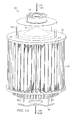
FIGURES 1A-1E show anantenna system 100 according to one embodiment. -
FIGURES 1A and1B show perspective views ofantenna system 100.FIGURE 1C shows anexample body 110 ofantenna system 100.FIGURES 1D and1E show cross-section views ofantenna system 100. - As shown in
FIGURES 1A and1B ,example antenna system 100 featuresbody 110, one ormore antenna boards 120, abase 130, afan 140, aninner cylinder cover 142, aflow enclosure 144, a fluid exit 146,antenna electronics 150, andfeedlines 152. Teachings of certain embodiments recognize the capability to provide afluid 105 flowing throughbody 110 andcool antenna boards 120 and/orantenna electronics 150. -
Body 110 may comprise any suitable material. In some embodiments,body 110 is constructed from heat-conductive materials. In one example embodiment,body 110 comprises aluminum or another suitable metal. An example embodiment ofbody 110 is discussed in greater detail with regard toFIGURE 1C .Body 110 may be of any suitable dimension. For example, in some embodiments, the height ofbody 110 is sized to correspond to the length ofantenna boards 120. As an example,antenna boards 120 may have a length approximately equal to less than the height of body 110 (as measured from between antenna plates 132). For example, in one embodiment, ifantenna boards 120 are approximately eight to ten inches long, thenbody 110 may be ten inches or higher. - In the example embodiment shown in
FIGURES 1A and1B ,body 110 is rigidly coupled tobase 130. Teachings of certain embodiments recognize thatbase 130 may allowantenna system 100 to be secured to any suitable structure, such as a building, vehicle, or mast. In some embodiments, however,body 110 is not rigidly coupled tobase 130. For example, in one embodiment,body 110 is releasably coupled tobase 130. - In this
example antenna system 100,antenna boards 120 connect to the outside ofbody 110,antenna electronics 150 are disposed withinbody 110, and feedlines 152 electricallycouple antenna boards 120 toantenna electronics 150.Antenna boards 120 may include any components configured to aid in transmitting and/or receiving electromagnetic waves or signals, such as RF signals or microwave signals. For example, in some embodiments,antenna boards 120 may comprise transmit/receive integrated microwave module (TRIMM) cards.Example antenna electronics 150 may include, but are not limited to, components operable to provide power and/or signals to or receive power and/or signals fromantenna boards 120. Examples ofantenna electronics 150 include power supplies, EMI filters, and RF dividers. In one example,antenna electronics 150 includes a power supply that provides power toantenna boards 120.Feedlines 152 may include any suitable transmission lines, such as copper (or other metal) transmission lines. In some embodiments,antenna system 100 does not includefeedlines 152. For example, in some embodiments,antenna boards 120 communicate withantenna electronics 150 solely throughantenna ports 122. - As shown in
FIGURE 1C ,example body 110 may include aninner cylinder 112 and anouter cylinder 116.Inner cylinder 112 andouter cylinder 116 may form a chamber through whichfluid 105 may flow. Teachings of certain embodiments recognize that this chamber may receive a flow offluid 105 in any suitable direction (such as providingfluid 105 tobody 110 from either open end) and at any suitable speed. For example, in some embodiments, a flow offluid 105 may include stagnant air within the chamber. - Fins 118 may be disposed between
inner cylinder 112 andouter cylinder 116.Inner cylinder 112 may includemounting structures 114 for mounting and/or securingantenna electronics 150.Outer cylinder 116 may includeantenna ports 122 configured to receiveantenna boards 120. Teachings of certain embodiments recognize the ability to provide fluid 105 betweeninner cylinder 112 andouter cylinder 116 tocool antenna boards 120 and/orantenna electronics 150. For example, in some embodiments,fins 118 may increase transfer of thermal energy betweenfluid 105 andantenna boards 120 and/orelectronics 150. - In some embodiments,
inner cylinder 112 and/orouter cylinder 116 are right circular cylinders. In other embodiments,inner cylinder 112 and/orouter cylinder 116 are not circular cylinders (such as oval, elliptic, oblique, or parabolic cylinders) and are not right angle cylinders (such as cylinders with an angle of less than or greater than 90 degrees). Teachings of certain embodiments recognize that any suitable shapes may be used, such as spheres or three-dimensional quadrilaterals. -
Inner cylinder 112, mountingstructures 114, andouter cylinder 116 may comprise any suitable material. In some embodiments,inner cylinder 112, mountingstructures 114, andouter cylinder 116 are constructed from heat-conductive materials. In one example embodiment,inner cylinder 112, mountingstructures 114, andouter cylinder 116 comprise aluminum or another suitable metal. Teachings of certain embodiments recognize thatantenna electronics 150 may be secured to mountingstructures 114 withininner cylinder 112. -
Fins 118 may comprise any suitable material. In some embodiments,fins 118 are constructed from heat-conductive materials. In one example embodiment,fins 118 comprise aluminum or another suitable metal. In some embodiments,fins 118 are vacuum brazed. Teachings of certain embodiments recognize the capability to provide fluid 105past fins 118 and transfer thermal energy betweenantenna system 100 andfluid 105. -
Antenna system 100 may include any suitable number offins 118, such as a number equal to the number ofantenna ports 122. In some embodiments,fins 118 may be separated by equal distances. In other embodiments, fins may not be separated by equal distances. In one example,fins 118 may be spaced closer together nearantenna boards 120.Fins 118 may be of any suitable thickness, such as a thickness approximately equal to the thickness ofantenna boards 120. In some embodiments, thickness offins 118 may be size to optimize thermal energy transfer betweenflow 105 andfins 118. In the illustrated embodiment,fins 118 are perpendicular toinner cylinder 112 andouter cylinder 116. However, teachings of certain embodiments recognize thatfins 112 may be oriented at any angle relative toinner cylinder 112 andouter cylinder 116. For example, in some embodiments, the angle betweenfins 112 andinner cylinder 112 may vary throughout the height ofbody 110. - Additionally, although the embodiment shown includes
fins 118, teachings also recognize embodiments withoutfins 118. For example, in some embodiments,fluid 105 may exchange thermal energy withinner cylinder 112 and/orouter cylinder 116 withoutfins 118. -
Antenna ports 122 may include any opening suitable for receivingantenna boards 120. For example, in some embodiments,antenna boards 120 are TRIMM cards.Antenna ports 122 may be slots configured to receive TRIMM cards.Antenna ports 122 include electrical connections toantenna boards 120. For example, in some embodiments,antenna ports 122 may electrically coupleantenna boards 120 toantenna electronics 150 in lieu of, or in addition to,feedlines 152. - Returning to
FIGURES 1A and1B , in some embodiments,fan 140 providesfluid 105. Examples offluid 105 may include, but are not limited to, gases (such as air) and liquids (such as water and liquid refrigerants). In one example embodiment,fluid 105 is ambient air that includes particulates or debris, such as sand, dirt, or trash. Accordingly, teachings of certain embodiments recognize thatcylinder cover 142 may prevent fluid 105 from enteringinner cylinder 112 and interfering with performance ofantenna electronics 150. In some embodiments,flow enclosure 144 may direct flow 105 towardsbody 110. Teachings of certain embodiments also recognize the capability to increase the fluid pressure withinflow enclosure 144 and increase fluid flow efficiency. - As shown in
FIGURES 1C-1E , in some embodiments,fins 118 may be aligned withantenna ports 122 andantenna boards 120. For example, inFIGURES 1C and1E , eachfin 118 connects toouter cylinder 116 aligned opposite from a correspondingantenna port 122. Teachings of certain embodiments recognize that aligningfins 118 withantenna ports 122 may improve thermal transfer betweenbody 110 andantenna cards 120. Teachings of certain embodiments also recognize that aligningfeedlines 152 parallel withfins 118 betweeninner cylinder 112 andouter cylinder 116 may reduce drag offluid 105 flowing pastfeedlines 152. However, in other embodiments feedlines 152 are not parallel withcorresponding fins 118, such as, for example, when the number offeedline 152 does not match the number offins 118. For example, if an embodiment has tenfeedlines 152 evenly spaced aroundbody 110 and eightfins 118 also evenly spaced aroundbody 110, then some of thefeedlines 152 will not correspond to afin 118.Feedlines 152 may also be arranged in any suitable manner to avoid contact withfluid 105. - In some embodiments,
antenna plates 132 may be configured on one or both sides ofantenna boards 120. In some embodiments,antenna plates 132 provide structural support toantenna boards 120. For example, in some embodiments,antenna boards 120 may includeadditional antenna ports 122 for receivingantenna boards 120. Anexample antenna plate 132 withantenna ports 122 will be discussed in greater detail with regard toFIGURE 2C . In some embodiments,antenna plates 132 do not touchantenna boards 120. For example, ifbody 110 is higher than the length ofantenna boards 120, thenantenna plates 132 may not touchantenna boards 120. -
FIGURES 2A and2B showexample antenna boards 120 according to one embodiment. In this example embodiment,antenna boards 120 are TRIMM cards. In this example, theantenna board 120 includes anantenna card 124,connection pieces 126, a mountingboard 128.Antenna card 124 may include any electronic component configured to aid in transmitting and/or receiving electromagnetic waves or signals.Connection pieces 126 may include any suitable components to physically and/or electronically coupleantenna boards 120 toantenna ports 122. For example, in some embodiments,connection pieces 126 include copper traces for electrical communication withantenna ports 122. In some embodiments, connection pieces include wedges configured to match into locking grooves associated withantenna ports 122. Mountingboard 128 may include any physical structure suitable for hostingantenna card 124 and/orconnection pieces 126. In some embodiments,antenna card 124 and mountingboard 128 are integrated into a common structure, such as a printed circuit board with various electronic components mounted to it. -
FIGURE 2C showsantenna board 120 connected toantenna ports 122 according to one embodiment. In this example,antenna ports 122 are configured onouter cylinder 118 andantenna plate 132. In this example,antenna board 120 electrically connects toantenna ports 122 onouter cylinder 118, and theantenna ports 122 onantenna plate 132 align andsecure antenna boards 120. - In the example embodiments of
FIGURES 1A-1E ,antenna boards 120 are connected around the outside ofbody 110. Teachings of certain embodiments recognize that this configuration may allowantenna boards 120 to transmit and receive signals in multiple directions, such as above, below, and radiating outward. However, some antenna systems may only be concerned with transmitting and receiving signals in specified directions. Accordingly, teachings of certain embodiments recognize the ability to orientantenna boards 120 to maximize transmission and receipt of signals in specified directions. -
FIGURES 3A and 3B showantenna cooling systems 100' and 100" according to two embodiments. Antenna cooling system 100' features a body 110' and antenna boards 120'.Antenna cooling system 100" features abody 110" andantenna boards 120". - In
FIGURE 3A , antenna cooling system 100' is configured to transmit and receive signals above the antenna system 100'. In this example, body 110' may be smaller at the top of antenna system 100' to increase transmission and receipt of signals above antenna system 100'. In addition, body 110' may be larger at the bottom of antenna system 100' to store electronic components. - In
FIGURE 3B ,antenna cooling system 100" is configured to transmit and receive signals below theantenna system 100". In this example,body 110" may be smaller at the bottom ofantenna system 100" to increase transmission and receipt of signals belowantenna system 100". In addition,body 110" may be larger at the top ofantenna system 100" to store electronic components. -
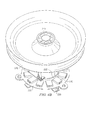
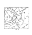
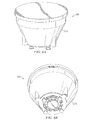
FIGURES 4A-4F show anantenna system 200 according to one embodiment.FIGURES 4A and4B show perspective views ofantenna system 200.FIGURE 4C shows an underside view ofantenna system 200.FIGURE 4D shows anexample body 210 ofantenna system 200.FIGURE 4E shows a cross-section view ofantenna system 200.FIGURE 4F shows a perspective cross-section view ofantenna system 200. - In this example embodiment,
antenna system 200 featuresbody 210,antenna modules 220, abase 230, afan 240, aflow diverter 242,exterior antenna electronics 250a, andinterior electronics 250b. In this example, fluid 205 flows throughbody 210 and then outflow diverter 242 tocool antenna boards 220,exterior antenna electronics 250a, and/orinterior electronics 250b. However, in some embodiments, fluid 205 flows intoflow diverter 242 and then throughbody 210. -
Body 210 may comprise any suitable material. In some embodiments,body 210 is constructed from heat-conductive materials. In one example embodiment,body 210 comprises aluminum or another suitable metal. An example embodiment ofbody 210 is discussed in greater detail with regard toFIGURE 4D . - In the example embodiment shown in
FIGURE 2A ,body 210 is rigidly coupled tobase 230. Teachings of certain embodiments recognize thatbase 230 may allowantenna system 200 to be secured to any suitable structure, such as a building, vehicle, or mast. - As shown in
FIGURES 4B and4C ,antenna modules 220 may be mounted outside ofbody 210. In this example,antenna modules 230 are mounted toantenna plate 232. In this example,antenna modules 220 may be electrically coupled toexterior antenna electronics 250a and/orinterior electronics 250b. For example, in one embodiment,antenna modules 220 connect to antenna ports 222', which then connect tointerior electronics 250b. - Example
exterior antenna electronics 250a andinterior electronics 250b may include, but are not limited to, components operable to provide power and/or signals to or receive power and/or signals fromantenna boards 120. Examples ofexterior antenna electronics 250a andinterior electronics 250b include power supplies, EMI filters, and RF dividers. In one example, a power supply insidebody 210 provides power toantenna boards 220 through antenna ports 222'. In another example, RF dividers are stored outsidebody 210, and EMI filters and power supplies are stored insidebody 210. - As shown in
FIGURE 4D ,example body 210 may include aninner cylinder 212 and anouter cylinder 216.Inner cylinder 212 andouter cylinder 216 may form a chamber through whichfluid 205 may flow. Teachings of certain embodiments recognize that this chamber may receive a flow offluid 205 in any suitable direction and at any suitable speed. For example, in some embodiments, a flow offluid 205 may include stagnant air within the chamber. -
Inner cylinder 212 may include mountingstructures 214 for mounting and/or securinginterior electronics 250b.External electronics 250a may be mounted and/or secured toouter cylinder 216. -
Fins 218 andheat pipes 262 may be disposed betweeninner cylinder 212 andouter cylinder 216. In this example,heat pipes 262 also extend out ofbody 210 and are coupled toantenna plate 232, whereheat pipes 262 are in thermal communication withantenna modules 220. - Teachings of certain embodiments recognize the ability to provide fluid 105 between
inner cylinder 112 andouter cylinder 116 tocool antenna modules 220,external electronics 250a, and/orinterior electronics 250b. For example, in some embodiments,fins 118 may increase transfer of thermal energy betweenfluid 105 andantenna modules 220,external electronics 250a, and/orinterior electronics 250b. - Additionally, although the embodiment shown includes
fins 218, teachings also recognize embodiments withoutfins 218. For example, in some embodiments,fluid 105 may exchange thermal energy withinner cylinder 212 and/orouter cylinder 216 withoutfins 218. - In some embodiments,
inner cylinder 212 and/orouter cylinder 216 are right circular cylinders. In other embodiments,inner cylinder 212 and/orouter cylinder 216 are not circular cylinders and are not right circular cylinders. Teachings of certain embodiments recognize that any suitable shapes may be used, such as spheres and three-dimensional quadrilaterals. -
Inner cylinder 212, mountingstructures 214, andouter cylinder 216 may comprise any suitable material. In some embodiments,inner cylinder 212, mountingstructures 214, andouter cylinder 216 are constructed from heat-conductive materials. In one example embodiment,inner cylinder 212, mountingstructures 214, andouter cylinder 216 comprise aluminum or another suitable metal. Teachings of certain embodiments recognize thatinterior electronics 250b may be secured to mountingstructures 214 withininner cylinder 212. -
Fins 218 may comprise any suitable material. In some embodiments,fins 218 are constructed from heat-conductive materials. In one example embodiment,fins 118 comprise aluminum or another suitable metal. In some embodiments,fins 218 are vacuum brazed. Teachings of certain embodiments recognize the capability to provide fluid 205past fins 218 and transfer thermal energy betweenantenna system 200 andfluid 205. - Additional examples of
body 210,inner cylinder 212, mountingequipment 214,outer cylinder 216,fins 218, andantenna ports 222 may include features frombody 110,inner cylinder 112, mountingequipment 114,outer cylinder 116,fins 118, andantenna ports 122. - In some embodiments,
fan 240 providesfluid 205. In theexample antenna system 200,fan 240 draws fluid 205 up throughbody 210. Examples offluid 205 may include, but are not limited to, gases (such as air) and liquids (such as water and liquid refrigerants). -
FIGURES 5A-5C show additional views ofantenna system 200 according to one embodiment.FIGURE 5A showsheat pipes 260 disposed withinbody 210 and extending toantenna plate 232.Heat pipes 260 may be secured withinbody 210 byheat pipe restraints 262. -
FIGURE 5B showsantenna plate 232. In this example,antenna plate 232 includes openings forantenna modules 220 to contact and be in thermal communication withheat pipes 260. In another example embodiment,antenna plate 232 does not include openings, andantenna modules 220 are in thermal communication withheat pipes 260 throughantenna plate 232. -
FIGURE 5C shows another example of anantenna port 222". Teachings of certain embodiments recognize that antenna ports may be configured to connect to anysuitable antenna module 220. In another example embodiment,antenna modules 220 may be TRIMM cards, andantenna ports 222" may be configured to receive TRIMM cards. -
FIGURES 6A and 6B show antenna system 200 with anexample radome 270. A radome may include any protective cover. In some examples, a radome may be constructed from material that minimally attenuates the electromagnetic signal transmitted or received by the antenna. Radomes may protectantenna system 200 from the environment (e.g., wind, rain, ice, sand, and ultraviolet rays) and/or concealantenna system 200 from public view. Teachings of certain embodiments recognize thatradome 270 may include openings to facilitate flow offluid 205 into and out ofantenna system 200. - Modifications, additions, or omissions may be made to the systems and apparatuses described herein without departing from the scope of the invention. The components of the systems and apparatuses may be integrated or separated. Moreover, the operations of the systems and apparatuses may be performed by more, fewer, or other components. The methods may include more, fewer, or other steps. Additionally, steps may be performed in any suitable order. Additionally, operations of the systems and apparatuses may be performed using any suitable logic. As used in this document, "each" refers to each member of a set or each member of a subset of a set.
- Although several embodiments have been illustrated and described in detail, substitutions and alterations are possible without departing from the spirit and scope of the present invention, as defined by the appended claims.
- To aid the Patent Office, and any readers of any patent issued on this application in interpreting the claims appended hereto, applicants wish to note that they do not intend any of the appended claims to invoke paragraph 6 of 35 U.S.C. § 112 as it exists on the date of filing hereof unless the words "means for" or "step for" are explicitly used in the particular claim.
Claims (17)
- An antenna cooling system, comprising:a first cylinder;a second cylinder substantially concentric to the first cylinder, and forming a chamber between the first cylinder and the second cylinder, the chamber configured to receive a fluid flow;a plurality of fins disposed within the chamber and rigidly coupled to the first cylinder and the second cylinder, the plurality of fins configured to transmit thermal energy to the fluid flow; and(i) a plurality of ports coupled to the second cylinder, each port configured to receive an antenna unit; or(ii) a plurality of heat pipes disposed between the first cylinder and the second cylinder, the plurality of heat pipes configured to be in thermal communication with a plurality of antenna units.
- The antenna cooling system of claim 1, or the method of claim 8, each port of the plurality of ports coupling to the second cylinder opposite from a corresponding fin of the plurality of fins.
- The antenna cooling system of claim 1, or of claim 2, further comprising a plurality of feedlines, each feedline of the plurality of feedlines aligned parallel with a corresponding fin of the plurality of fins, the plurality of feedlines configured to electronically couple the plurality of ports to electronics disposed within the first cylinder; or electronically communicating with the plurality of antenna units comprising electronically coupling the plurality of ports to electronics disposed within the first cylinder; or
the method of claim 8, electronically communicating with the plurality of antenna units comprising electronically coupling the plurality of ports to electronics disposed within the first cylinder. - The antenna cooling system of claim 1, or of claim 2 or of claim 3, further comprising a power supply disposed within the first cylinder.
- The antenna cooling system of claim 1, or of any of claims 2 to 4, further comprising a cylinder cover coupled to the first cylinder and configured to prevent at least some of the fluid flow from entering the first cylinder.
- The antenna cooling system of claim 1, or of any of claims 2 to 5, each port configured to receive a transmit/receive integrated microwave module (TRIMM) card.
- The antenna cooling system of claim 1, or of any of claims 2 to 6, further comprising a flow diverter coupled to the second cylinder and configured to:receive the fluid flow in a first direction;direct the fluid flow in a second direction substantially perpendicular to the first direction; andprovide the fluid flow to the chamber in the second direction.
- A method of cooling an antenna system, comprising:receiving a fluid flow through a chamber, the chamber formed between a first cylinder and a second cylinder substantially concentric to the first cylinder;transferring thermal energy from a plurality of fins to the fluid flow, the plurality of fins disposed within the chamber and rigidly coupled to the first cylinder and the second cylinder; and(i) electronically communicating with a plurality of antenna units through a plurality of ports of the second cylinder, each port configured to receive an antenna unit; or(ii) transferring thermal energy from a plurality of heat pipes to the fluid flow, the plurality of heat pipes disposed between the first cylinder and the second cylinder, the plurality of heat pipes in thermal communication with a plurality of antenna units.
- The antenna cooling system of claim 1, or the method of claim 8, comprising both features (i) and (ii) of claim 1, or of claim 8.
- The antenna cooling system of claim 1, including feature (i) or feature (ii), or the system of any of claims 2 to 7, or claim 9, further comprising:a control circuit card disposed within the first cylinder; anda plurality of feedlines configured to electronically couple the control circuit card to the plurality of antenna units.
- The antenna cooling system of claim 1, including feature (i) or feature (ii), or the system of any of claims 2 to 7, or of claim 9, or of claim 10, further comprising a power supply disposed within the first cylinder.
- The antenna cooling system of claim 1, including feature (i) or feature (ii), or the system of claim 9, or claim 10 or claim 11, further comprising an EMI filter disposed within the first cylinder.
- The antenna cooling system of claim 1, including feature (i) or feature (ii), or the system of any of claims 9 to 12, further comprising a cylinder cover coupled to the first cylinder and configured to prevent at least some of the fluid from entering the first cylinder.
- The antenna cooling system of claim 1, including feature (i) or feature (ii), or the system of any of claims 9 to 13, further comprising a flow diverter coupled to the second cylinder and configured to:receive the fluid flow in a first direction;direct the fluid flow in a second direction substantially perpendicular to the first direction; andprovide the fluid flow to the chamber in the second direction.
- The antenna cooling system of claim 1, including feature (i) or feature (ii), or the system of any of claims 9 to 14, further comprising a flow diverter coupled to the second cylinder and configured to:receive the fluid flow from the chamber in a first direction; anddirect the fluid flow in a second direction substantially perpendicular to the first direction.
- The method of claim 8, or of any method claim dependant from claim 8, further comprising:receiving the fluid flow in a first direction;directing the fluid flow in a second direction substantially perpendicular to the first direction; andproviding the fluid flow to the chamber in the second direction.
- The method of claim 8, or of any method claim dependant from claim 8, further comprising:receiving the fluid flow from the chamber in a first direction; anddirecting the fluid flow in a second direction substantially perpendicular to the first direction.
Applications Claiming Priority (1)
| Application Number | Priority Date | Filing Date | Title |
|---|---|---|---|
| US12/851,289 US8279604B2 (en) | 2010-08-05 | 2010-08-05 | Cooling system for cylindrical antenna |
Publications (2)
| Publication Number | Publication Date |
|---|---|
| EP2416441A1 true EP2416441A1 (en) | 2012-02-08 |
| EP2416441B1 EP2416441B1 (en) | 2013-11-27 |
Family
ID=44501624
Family Applications (1)
| Application Number | Title | Priority Date | Filing Date |
|---|---|---|---|
| EP11168524.4A Active EP2416441B1 (en) | 2010-08-05 | 2011-06-01 | Cooling system for cylindrical antenna |
Country Status (2)
| Country | Link |
|---|---|
| US (1) | US8279604B2 (en) |
| EP (1) | EP2416441B1 (en) |
Families Citing this family (19)
| Publication number | Priority date | Publication date | Assignee | Title |
|---|---|---|---|---|
| US8681501B2 (en) * | 2010-12-17 | 2014-03-25 | Aruba Networks, Inc. | Heat dissipation unit for a wireless network device |
| USD715479S1 (en) * | 2012-10-26 | 2014-10-14 | John F. JOHNSTON | Light-generating system |
| AU2014272887B2 (en) * | 2013-05-31 | 2017-12-14 | Bae Systems Plc | Improvements in and relating to antenna systems |
| US10327357B2 (en) * | 2014-09-18 | 2019-06-18 | Artesyn Embedded Computing, Inc. | Thermal conduction to a cylindrical shaft |
| TWM523267U (en) * | 2015-07-16 | 2016-06-01 | 鋐寶科技股份有限公司 | Electronic device |
| EP3392969B1 (en) * | 2015-12-17 | 2021-10-20 | Mitsubishi Electric Corporation | Phased array antenna |
| FR3064878B1 (en) * | 2017-03-31 | 2020-01-24 | Aptiv Technologies Limited | DEVICE FOR HEAT DISSIPATION OF AN ELECTRONIC DEVICE |
| US11540881B2 (en) | 2018-08-23 | 2023-01-03 | Boston Scientific Scimed, Inc. | Microwave ablation probe with radiofrequency impedance sensing |
| US11382682B2 (en) | 2018-11-28 | 2022-07-12 | Boston Scientific Scimed, Inc. | Closed irrigated radiofrequency bipolar tined ablation probe |
| US10938084B2 (en) * | 2018-12-07 | 2021-03-02 | Intel Corporation | Cooling system for radio |
| US10886592B2 (en) | 2018-12-11 | 2021-01-05 | Orbit Advanced Technologies, Inc. | Automated feed source changer for a compact test range |
| US11957409B2 (en) | 2018-12-19 | 2024-04-16 | Boston Scientific Scimed, Inc. | Irrigation cooling structure for microwave ablation tissue probe |
| KR102616879B1 (en) * | 2019-08-19 | 2023-12-26 | 삼성전자주식회사 | Electronic device including composite heat radiating member and method of manufacturing the same |
| US12040539B2 (en) | 2020-11-25 | 2024-07-16 | Raytheon Company | Mitigation of ripple in element pattern of geodesic antenna |
| US11424546B2 (en) | 2020-12-02 | 2022-08-23 | Raytheon Company | Modified ground planes to increase gains in element patterns of geodesic antennas |
| JP2024518818A (en) | 2021-04-20 | 2024-05-07 | ヴィアサット,インコーポレイテッド | Satellite antenna anti-icing system and method |
| EP4425699A4 (en) * | 2021-10-27 | 2026-01-21 | Toshiba Kk | AIR-COOLED COOLING STRUCTURE AND ANTENNA DEVICE |
| US12546878B2 (en) | 2022-05-20 | 2026-02-10 | Anduril Industries, Inc. | Detecting, tracking, and transmitting to identified objects using models in a modular system |
| CN116130921A (en) * | 2022-12-06 | 2023-05-16 | 中国船舶集团有限公司第七二四研究所 | Internal-conduction heat-dissipation circular phased array antenna structure |
Citations (2)
| Publication number | Priority date | Publication date | Assignee | Title |
|---|---|---|---|---|
| DE4030796A1 (en) * | 1989-09-28 | 1991-04-11 | Siemens Ag | PHASE CONTROLLED GROUP ANTENNA WITH RADIATION ELEMENTS ARRANGED IN THE VOLUME OF A THOUGHTED BALL |
| US7061446B1 (en) * | 2002-10-24 | 2006-06-13 | Raytheon Company | Method and apparatus for controlling temperature gradients within a structure being cooled |
Family Cites Families (24)
| Publication number | Priority date | Publication date | Assignee | Title |
|---|---|---|---|---|
| NL251457A (en) * | 1959-05-18 | |||
| US4094937A (en) | 1976-04-15 | 1978-06-13 | Zurn Industries, Inc. | Cylindrical multi-fan counterflow cooling tower |
| US4285027A (en) | 1979-01-12 | 1981-08-18 | Daikin Kogyo Co., Ltd. | Cooling system |
| US4528615A (en) * | 1983-05-13 | 1985-07-09 | At&T Bell Laboratories | Repeater housing and circuit mounting structure |
| US4851856A (en) | 1988-02-16 | 1989-07-25 | Westinghouse Electric Corp. | Flexible diaphragm cooling device for microwave antennas |
| US5735847A (en) | 1995-08-15 | 1998-04-07 | Zomed International, Inc. | Multiple antenna ablation apparatus and method with cooling element |
| SE504950C2 (en) * | 1995-09-29 | 1997-06-02 | Ericsson Telefon Ab L M | Device for cooling electronic devices |
| DE19648253C2 (en) | 1996-11-22 | 2002-04-04 | Siemens Ag | Pulse tube cooler and use of the same |
| US5829519A (en) | 1997-03-10 | 1998-11-03 | Enhanced Energy, Inc. | Subterranean antenna cooling system |
| US6292556B1 (en) * | 1997-11-06 | 2001-09-18 | Anacapa Technology, Inc. | Local loop telecommunication repeater housings employing thermal collection, transfer and distribution via solid thermal conduction |
| US6118662A (en) * | 1999-11-05 | 2000-09-12 | Special Product Company | Enclosure for telecommunications equipment |
| US6404637B2 (en) * | 2000-02-14 | 2002-06-11 | Special Product Company | Concentrical slot telecommunications equipment enclosure |
| US6778389B1 (en) * | 2003-07-03 | 2004-08-17 | Visteon Global Technologies, Inc. | Microelectronic package with tubular housing |
| US7311703B2 (en) | 2003-07-18 | 2007-12-25 | Vivant Medical, Inc. | Devices and methods for cooling microwave antennas |
| US6865085B1 (en) * | 2003-09-26 | 2005-03-08 | Adc Dsl Systems, Inc. | Heat dissipation for electronic enclosures |
| US7263836B2 (en) | 2004-05-18 | 2007-09-04 | Schlumberger Technology Corporation | Vortex tube cooling system |
| US6862979B1 (en) | 2004-08-12 | 2005-03-08 | Jesus Antonio Silvestrini | Thermal conditioning system for heating and cooling cylindrical containers |
| US7443354B2 (en) | 2005-08-09 | 2008-10-28 | The Boeing Company | Compliant, internally cooled antenna apparatus and method |
| TWM286407U (en) * | 2005-10-11 | 2006-01-21 | Augux Co Ltd | Heat dissipation module |
| US7372705B1 (en) * | 2006-02-01 | 2008-05-13 | Cisco Technology, Inc. | Portable data routing device and method of use |
| US7885037B2 (en) * | 2006-08-18 | 2011-02-08 | Oracle America, Inc. | Disk storage cartridge |
| US7940524B2 (en) | 2007-10-01 | 2011-05-10 | Raytheon Company | Remote cooling of a phased array antenna |
| US8292880B2 (en) | 2007-11-27 | 2012-10-23 | Vivant Medical, Inc. | Targeted cooling of deployable microwave antenna |
| US8004844B2 (en) * | 2008-03-12 | 2011-08-23 | Kmw, Inc. | Enclosure device of wireless communication apparatus |
-
2010
- 2010-08-05 US US12/851,289 patent/US8279604B2/en active Active
-
2011
- 2011-06-01 EP EP11168524.4A patent/EP2416441B1/en active Active
Patent Citations (2)
| Publication number | Priority date | Publication date | Assignee | Title |
|---|---|---|---|---|
| DE4030796A1 (en) * | 1989-09-28 | 1991-04-11 | Siemens Ag | PHASE CONTROLLED GROUP ANTENNA WITH RADIATION ELEMENTS ARRANGED IN THE VOLUME OF A THOUGHTED BALL |
| US7061446B1 (en) * | 2002-10-24 | 2006-06-13 | Raytheon Company | Method and apparatus for controlling temperature gradients within a structure being cooled |
Also Published As
| Publication number | Publication date |
|---|---|
| US8279604B2 (en) | 2012-10-02 |
| EP2416441B1 (en) | 2013-11-27 |
| US20120033383A1 (en) | 2012-02-09 |
Similar Documents
| Publication | Publication Date | Title |
|---|---|---|
| US8279604B2 (en) | Cooling system for cylindrical antenna | |
| EP3780260B1 (en) | Multiple input and multiple output antenna apparatus | |
| EP2983302B1 (en) | Radio frequency unit and integrated antenna with improved heat dissipation | |
| US8937574B2 (en) | Lightweight air-cooled transmit/receive unit and active phased array including same | |
| US10784589B2 (en) | Wireless communication device | |
| US6876323B2 (en) | Amplitude and phase-controlled antennas-subsystem | |
| CN211907697U (en) | Conformal electric scanning array antenna | |
| EP1792365B1 (en) | Pin fin ground plane for a patch antenna | |
| EP2205923B1 (en) | Remote cooling of a phased array antenna | |
| CN109245793A (en) | A kind of multichannel tile type phased array transmitting-receiving array and its manufacturing method | |
| US8525729B1 (en) | Antenna tiles with ground cavities integrated into support structure | |
| CN208675233U (en) | A multi-channel tiled phased array transceiver array | |
| US12355131B2 (en) | Antenna apparatus and radome | |
| CA2676948C (en) | An array antenna comprising means to suppress the coupling effect in the dielectric gaps between its radiator elements without establishing galvanic contacts | |
| CN109511253A (en) | A kind of Connectors for Active Phased Array Radar assembly radiating temperature control technique | |
| US9780458B2 (en) | Methods and apparatus for antenna having dual polarized radiating elements with enhanced heat dissipation | |
| CN217740763U (en) | Phased array antenna structure | |
| EP3044827B1 (en) | Phased array antenna assembly | |
| EP4238233B1 (en) | Innovative three-dimensional u-shaped architecture for transmit/receive modules of aesa systems | |
| US7391382B1 (en) | Transmit/receive module and method of forming same | |
| JP2023541680A (en) | Antenna subarray block with heat dissipation properties | |
| Temir et al. | A method of electro-mechanical packaging with embedded cooling to design fully-functional core structures for scalable active phased array radars | |
| JP3942849B2 (en) | Array antenna cooling structure | |
| CN115693139A (en) | High-density base station type self-heat-dissipation planar phased array | |
| US7456789B1 (en) | Integrated subarray structure |
Legal Events
| Date | Code | Title | Description |
|---|---|---|---|
| AK | Designated contracting states |
Kind code of ref document: A1 Designated state(s): AL AT BE BG CH CY CZ DE DK EE ES FI FR GB GR HR HU IE IS IT LI LT LU LV MC MK MT NL NO PL PT RO RS SE SI SK SM TR |
|
| AX | Request for extension of the european patent |
Extension state: BA ME |
|
| PUAI | Public reference made under article 153(3) epc to a published international application that has entered the european phase |
Free format text: ORIGINAL CODE: 0009012 |
|
| 17P | Request for examination filed |
Effective date: 20120808 |
|
| GRAP | Despatch of communication of intention to grant a patent |
Free format text: ORIGINAL CODE: EPIDOSNIGR1 |
|
| RIC1 | Information provided on ipc code assigned before grant |
Ipc: H01Q 21/20 20060101ALI20130618BHEP Ipc: H01Q 1/12 20060101ALN20130618BHEP Ipc: H01Q 1/42 20060101ALN20130618BHEP Ipc: H01Q 1/02 20060101AFI20130618BHEP |
|
| INTG | Intention to grant announced |
Effective date: 20130702 |
|
| GRAS | Grant fee paid |
Free format text: ORIGINAL CODE: EPIDOSNIGR3 |
|
| GRAA | (expected) grant |
Free format text: ORIGINAL CODE: 0009210 |
|
| AK | Designated contracting states |
Kind code of ref document: B1 Designated state(s): AL AT BE BG CH CY CZ DE DK EE ES FI FR GB GR HR HU IE IS IT LI LT LU LV MC MK MT NL NO PL PT RO RS SE SI SK SM TR |
|
| REG | Reference to a national code |
Ref country code: GB Ref legal event code: FG4D |
|
| REG | Reference to a national code |
Ref country code: CH Ref legal event code: EP |
|
| REG | Reference to a national code |
Ref country code: AT Ref legal event code: REF Ref document number: 643032 Country of ref document: AT Kind code of ref document: T Effective date: 20131215 |
|
| REG | Reference to a national code |
Ref country code: IE Ref legal event code: FG4D |
|
| REG | Reference to a national code |
Ref country code: DE Ref legal event code: R096 Ref document number: 602011003923 Country of ref document: DE Effective date: 20140130 |
|
| REG | Reference to a national code |
Ref country code: NL Ref legal event code: VDEP Effective date: 20131127 |
|
| REG | Reference to a national code |
Ref country code: AT Ref legal event code: MK05 Ref document number: 643032 Country of ref document: AT Kind code of ref document: T Effective date: 20131127 |
|
| REG | Reference to a national code |
Ref country code: LT Ref legal event code: MG4D |
|
| PG25 | Lapsed in a contracting state [announced via postgrant information from national office to epo] |
Ref country code: NL Free format text: LAPSE BECAUSE OF FAILURE TO SUBMIT A TRANSLATION OF THE DESCRIPTION OR TO PAY THE FEE WITHIN THE PRESCRIBED TIME-LIMIT Effective date: 20131127 Ref country code: SE Free format text: LAPSE BECAUSE OF FAILURE TO SUBMIT A TRANSLATION OF THE DESCRIPTION OR TO PAY THE FEE WITHIN THE PRESCRIBED TIME-LIMIT Effective date: 20131127 Ref country code: HR Free format text: LAPSE BECAUSE OF FAILURE TO SUBMIT A TRANSLATION OF THE DESCRIPTION OR TO PAY THE FEE WITHIN THE PRESCRIBED TIME-LIMIT Effective date: 20131127 Ref country code: NO Free format text: LAPSE BECAUSE OF FAILURE TO SUBMIT A TRANSLATION OF THE DESCRIPTION OR TO PAY THE FEE WITHIN THE PRESCRIBED TIME-LIMIT Effective date: 20140227 Ref country code: FI Free format text: LAPSE BECAUSE OF FAILURE TO SUBMIT A TRANSLATION OF THE DESCRIPTION OR TO PAY THE FEE WITHIN THE PRESCRIBED TIME-LIMIT Effective date: 20131127 Ref country code: LT Free format text: LAPSE BECAUSE OF FAILURE TO SUBMIT A TRANSLATION OF THE DESCRIPTION OR TO PAY THE FEE WITHIN THE PRESCRIBED TIME-LIMIT Effective date: 20131127 Ref country code: IS Free format text: LAPSE BECAUSE OF FAILURE TO SUBMIT A TRANSLATION OF THE DESCRIPTION OR TO PAY THE FEE WITHIN THE PRESCRIBED TIME-LIMIT Effective date: 20140327 |
|
| PG25 | Lapsed in a contracting state [announced via postgrant information from national office to epo] |
Ref country code: AT Free format text: LAPSE BECAUSE OF FAILURE TO SUBMIT A TRANSLATION OF THE DESCRIPTION OR TO PAY THE FEE WITHIN THE PRESCRIBED TIME-LIMIT Effective date: 20131127 Ref country code: RS Free format text: LAPSE BECAUSE OF FAILURE TO SUBMIT A TRANSLATION OF THE DESCRIPTION OR TO PAY THE FEE WITHIN THE PRESCRIBED TIME-LIMIT Effective date: 20131127 Ref country code: CY Free format text: LAPSE BECAUSE OF FAILURE TO SUBMIT A TRANSLATION OF THE DESCRIPTION OR TO PAY THE FEE WITHIN THE PRESCRIBED TIME-LIMIT Effective date: 20131127 Ref country code: LV Free format text: LAPSE BECAUSE OF FAILURE TO SUBMIT A TRANSLATION OF THE DESCRIPTION OR TO PAY THE FEE WITHIN THE PRESCRIBED TIME-LIMIT Effective date: 20131127 Ref country code: BE Free format text: LAPSE BECAUSE OF FAILURE TO SUBMIT A TRANSLATION OF THE DESCRIPTION OR TO PAY THE FEE WITHIN THE PRESCRIBED TIME-LIMIT Effective date: 20131127 Ref country code: ES Free format text: LAPSE BECAUSE OF FAILURE TO SUBMIT A TRANSLATION OF THE DESCRIPTION OR TO PAY THE FEE WITHIN THE PRESCRIBED TIME-LIMIT Effective date: 20131127 |
|
| PG25 | Lapsed in a contracting state [announced via postgrant information from national office to epo] |
Ref country code: PT Free format text: LAPSE BECAUSE OF FAILURE TO SUBMIT A TRANSLATION OF THE DESCRIPTION OR TO PAY THE FEE WITHIN THE PRESCRIBED TIME-LIMIT Effective date: 20140327 |
|
| PG25 | Lapsed in a contracting state [announced via postgrant information from national office to epo] |
Ref country code: EE Free format text: LAPSE BECAUSE OF FAILURE TO SUBMIT A TRANSLATION OF THE DESCRIPTION OR TO PAY THE FEE WITHIN THE PRESCRIBED TIME-LIMIT Effective date: 20131127 |
|
| REG | Reference to a national code |
Ref country code: DE Ref legal event code: R097 Ref document number: 602011003923 Country of ref document: DE |
|
| PG25 | Lapsed in a contracting state [announced via postgrant information from national office to epo] |
Ref country code: RO Free format text: LAPSE BECAUSE OF FAILURE TO SUBMIT A TRANSLATION OF THE DESCRIPTION OR TO PAY THE FEE WITHIN THE PRESCRIBED TIME-LIMIT Effective date: 20131127 Ref country code: CZ Free format text: LAPSE BECAUSE OF FAILURE TO SUBMIT A TRANSLATION OF THE DESCRIPTION OR TO PAY THE FEE WITHIN THE PRESCRIBED TIME-LIMIT Effective date: 20131127 Ref country code: PL Free format text: LAPSE BECAUSE OF FAILURE TO SUBMIT A TRANSLATION OF THE DESCRIPTION OR TO PAY THE FEE WITHIN THE PRESCRIBED TIME-LIMIT Effective date: 20131127 Ref country code: SK Free format text: LAPSE BECAUSE OF FAILURE TO SUBMIT A TRANSLATION OF THE DESCRIPTION OR TO PAY THE FEE WITHIN THE PRESCRIBED TIME-LIMIT Effective date: 20131127 |
|
| PG25 | Lapsed in a contracting state [announced via postgrant information from national office to epo] |
Ref country code: DK Free format text: LAPSE BECAUSE OF FAILURE TO SUBMIT A TRANSLATION OF THE DESCRIPTION OR TO PAY THE FEE WITHIN THE PRESCRIBED TIME-LIMIT Effective date: 20131127 |
|
| PLBE | No opposition filed within time limit |
Free format text: ORIGINAL CODE: 0009261 |
|
| STAA | Information on the status of an ep patent application or granted ep patent |
Free format text: STATUS: NO OPPOSITION FILED WITHIN TIME LIMIT |
|
| 26N | No opposition filed |
Effective date: 20140828 |
|
| REG | Reference to a national code |
Ref country code: DE Ref legal event code: R097 Ref document number: 602011003923 Country of ref document: DE Effective date: 20140828 |
|
| PG25 | Lapsed in a contracting state [announced via postgrant information from national office to epo] |
Ref country code: LU Free format text: LAPSE BECAUSE OF FAILURE TO SUBMIT A TRANSLATION OF THE DESCRIPTION OR TO PAY THE FEE WITHIN THE PRESCRIBED TIME-LIMIT Effective date: 20140601 Ref country code: MC Free format text: LAPSE BECAUSE OF FAILURE TO SUBMIT A TRANSLATION OF THE DESCRIPTION OR TO PAY THE FEE WITHIN THE PRESCRIBED TIME-LIMIT Effective date: 20131127 |
|
| REG | Reference to a national code |
Ref country code: CH Ref legal event code: PL |
|
| PG25 | Lapsed in a contracting state [announced via postgrant information from national office to epo] |
Ref country code: SI Free format text: LAPSE BECAUSE OF FAILURE TO SUBMIT A TRANSLATION OF THE DESCRIPTION OR TO PAY THE FEE WITHIN THE PRESCRIBED TIME-LIMIT Effective date: 20131127 |
|
| REG | Reference to a national code |
Ref country code: IE Ref legal event code: MM4A |
|
| PG25 | Lapsed in a contracting state [announced via postgrant information from national office to epo] |
Ref country code: LI Free format text: LAPSE BECAUSE OF NON-PAYMENT OF DUE FEES Effective date: 20140630 Ref country code: IE Free format text: LAPSE BECAUSE OF NON-PAYMENT OF DUE FEES Effective date: 20140601 Ref country code: CH Free format text: LAPSE BECAUSE OF NON-PAYMENT OF DUE FEES Effective date: 20140630 |
|
| PG25 | Lapsed in a contracting state [announced via postgrant information from national office to epo] |
Ref country code: MT Free format text: LAPSE BECAUSE OF FAILURE TO SUBMIT A TRANSLATION OF THE DESCRIPTION OR TO PAY THE FEE WITHIN THE PRESCRIBED TIME-LIMIT Effective date: 20131127 |
|
| PG25 | Lapsed in a contracting state [announced via postgrant information from national office to epo] |
Ref country code: SM Free format text: LAPSE BECAUSE OF FAILURE TO SUBMIT A TRANSLATION OF THE DESCRIPTION OR TO PAY THE FEE WITHIN THE PRESCRIBED TIME-LIMIT Effective date: 20131127 |
|
| REG | Reference to a national code |
Ref country code: FR Ref legal event code: PLFP Year of fee payment: 6 |
|
| PG25 | Lapsed in a contracting state [announced via postgrant information from national office to epo] |
Ref country code: GR Free format text: LAPSE BECAUSE OF FAILURE TO SUBMIT A TRANSLATION OF THE DESCRIPTION OR TO PAY THE FEE WITHIN THE PRESCRIBED TIME-LIMIT Effective date: 20140228 Ref country code: BG Free format text: LAPSE BECAUSE OF FAILURE TO SUBMIT A TRANSLATION OF THE DESCRIPTION OR TO PAY THE FEE WITHIN THE PRESCRIBED TIME-LIMIT Effective date: 20131127 |
|
| PG25 | Lapsed in a contracting state [announced via postgrant information from national office to epo] |
Ref country code: TR Free format text: LAPSE BECAUSE OF FAILURE TO SUBMIT A TRANSLATION OF THE DESCRIPTION OR TO PAY THE FEE WITHIN THE PRESCRIBED TIME-LIMIT Effective date: 20131127 Ref country code: HU Free format text: LAPSE BECAUSE OF FAILURE TO SUBMIT A TRANSLATION OF THE DESCRIPTION OR TO PAY THE FEE WITHIN THE PRESCRIBED TIME-LIMIT; INVALID AB INITIO Effective date: 20110601 |
|
| PGFP | Annual fee paid to national office [announced via postgrant information from national office to epo] |
Ref country code: GB Payment date: 20160601 Year of fee payment: 6 |
|
| PGFP | Annual fee paid to national office [announced via postgrant information from national office to epo] |
Ref country code: FR Payment date: 20160516 Year of fee payment: 6 |
|
| PGFP | Annual fee paid to national office [announced via postgrant information from national office to epo] |
Ref country code: IT Payment date: 20160621 Year of fee payment: 6 |
|
| GBPC | Gb: european patent ceased through non-payment of renewal fee |
Effective date: 20170601 |
|
| REG | Reference to a national code |
Ref country code: FR Ref legal event code: ST Effective date: 20180228 |
|
| PG25 | Lapsed in a contracting state [announced via postgrant information from national office to epo] |
Ref country code: GB Free format text: LAPSE BECAUSE OF NON-PAYMENT OF DUE FEES Effective date: 20170601 |
|
| PG25 | Lapsed in a contracting state [announced via postgrant information from national office to epo] |
Ref country code: IT Free format text: LAPSE BECAUSE OF NON-PAYMENT OF DUE FEES Effective date: 20170601 Ref country code: FR Free format text: LAPSE BECAUSE OF NON-PAYMENT OF DUE FEES Effective date: 20170630 |
|
| PG25 | Lapsed in a contracting state [announced via postgrant information from national office to epo] |
Ref country code: MK Free format text: LAPSE BECAUSE OF FAILURE TO SUBMIT A TRANSLATION OF THE DESCRIPTION OR TO PAY THE FEE WITHIN THE PRESCRIBED TIME-LIMIT Effective date: 20131127 |
|
| PG25 | Lapsed in a contracting state [announced via postgrant information from national office to epo] |
Ref country code: AL Free format text: LAPSE BECAUSE OF FAILURE TO SUBMIT A TRANSLATION OF THE DESCRIPTION OR TO PAY THE FEE WITHIN THE PRESCRIBED TIME-LIMIT Effective date: 20131127 |
|
| P01 | Opt-out of the competence of the unified patent court (upc) registered |
Effective date: 20230530 |
|
| PGFP | Annual fee paid to national office [announced via postgrant information from national office to epo] |
Ref country code: DE Payment date: 20250520 Year of fee payment: 15 |