EP2416199A1 - Vibrating Mirror Element - Google Patents
Vibrating Mirror Element Download PDFInfo
- Publication number
- EP2416199A1 EP2416199A1 EP11176280A EP11176280A EP2416199A1 EP 2416199 A1 EP2416199 A1 EP 2416199A1 EP 11176280 A EP11176280 A EP 11176280A EP 11176280 A EP11176280 A EP 11176280A EP 2416199 A1 EP2416199 A1 EP 2416199A1
- Authority
- EP
- European Patent Office
- Prior art keywords
- driving
- portions
- axis
- mirror
- driving portion
- Prior art date
- Legal status (The legal status is an assumption and is not a legal conclusion. Google has not performed a legal analysis and makes no representation as to the accuracy of the status listed.)
- Withdrawn
Links
- 230000003287 optical effect Effects 0.000 description 132
- 230000008878 coupling Effects 0.000 description 53
- 238000010168 coupling process Methods 0.000 description 53
- 238000005859 coupling reaction Methods 0.000 description 53
- 239000000758 substrate Substances 0.000 description 15
- VYPSYNLAJGMNEJ-UHFFFAOYSA-N Silicium dioxide Chemical compound O=[Si]=O VYPSYNLAJGMNEJ-UHFFFAOYSA-N 0.000 description 10
- 238000001020 plasma etching Methods 0.000 description 8
- 229910052681 coesite Inorganic materials 0.000 description 5
- 229910052906 cristobalite Inorganic materials 0.000 description 5
- 229910052451 lead zirconate titanate Inorganic materials 0.000 description 5
- 239000000377 silicon dioxide Substances 0.000 description 5
- 229910052682 stishovite Inorganic materials 0.000 description 5
- 229910052905 tridymite Inorganic materials 0.000 description 5
- 238000004519 manufacturing process Methods 0.000 description 4
- 239000000463 material Substances 0.000 description 3
- 229910052719 titanium Inorganic materials 0.000 description 3
- 239000010936 titanium Substances 0.000 description 3
- 229910052727 yttrium Inorganic materials 0.000 description 3
- RTAQQCXQSZGOHL-UHFFFAOYSA-N Titanium Chemical compound [Ti] RTAQQCXQSZGOHL-UHFFFAOYSA-N 0.000 description 2
- 229910052782 aluminium Inorganic materials 0.000 description 2
- 230000008859 change Effects 0.000 description 2
- 229910052804 chromium Inorganic materials 0.000 description 2
- 229910052802 copper Inorganic materials 0.000 description 2
- 229920001971 elastomer Polymers 0.000 description 2
- 239000000806 elastomer Substances 0.000 description 2
- HFGPZNIAWCZYJU-UHFFFAOYSA-N lead zirconate titanate Chemical compound [O-2].[O-2].[O-2].[O-2].[O-2].[Ti+4].[Zr+4].[Pb+2] HFGPZNIAWCZYJU-UHFFFAOYSA-N 0.000 description 2
- 230000004048 modification Effects 0.000 description 2
- 238000012986 modification Methods 0.000 description 2
- 229910052697 platinum Inorganic materials 0.000 description 2
- 238000007740 vapor deposition Methods 0.000 description 2
- XLOMVQKBTHCTTD-UHFFFAOYSA-N Zinc monoxide Chemical compound [Zn]=O XLOMVQKBTHCTTD-UHFFFAOYSA-N 0.000 description 1
- QCWXUUIWCKQGHC-UHFFFAOYSA-N Zirconium Chemical compound [Zr] QCWXUUIWCKQGHC-UHFFFAOYSA-N 0.000 description 1
- 229910052737 gold Inorganic materials 0.000 description 1
- 230000002401 inhibitory effect Effects 0.000 description 1
- 229910052746 lanthanum Inorganic materials 0.000 description 1
- 239000007769 metal material Substances 0.000 description 1
- 238000000206 photolithography Methods 0.000 description 1
- UKDIAJWKFXFVFG-UHFFFAOYSA-N potassium;oxido(dioxo)niobium Chemical compound [K+].[O-][Nb](=O)=O UKDIAJWKFXFVFG-UHFFFAOYSA-N 0.000 description 1
- 238000000926 separation method Methods 0.000 description 1
- UYLYBEXRJGPQSH-UHFFFAOYSA-N sodium;oxido(dioxo)niobium Chemical compound [Na+].[O-][Nb](=O)=O UYLYBEXRJGPQSH-UHFFFAOYSA-N 0.000 description 1
- 238000004544 sputter deposition Methods 0.000 description 1
- 238000001039 wet etching Methods 0.000 description 1
- 229910052726 zirconium Inorganic materials 0.000 description 1
Images



Classifications
-
- G—PHYSICS
- G02—OPTICS
- G02B—OPTICAL ELEMENTS, SYSTEMS OR APPARATUS
- G02B26/00—Optical devices or arrangements for the control of light using movable or deformable optical elements
- G02B26/08—Optical devices or arrangements for the control of light using movable or deformable optical elements for controlling the direction of light
- G02B26/0816—Optical devices or arrangements for the control of light using movable or deformable optical elements for controlling the direction of light by means of one or more reflecting elements
- G02B26/0833—Optical devices or arrangements for the control of light using movable or deformable optical elements for controlling the direction of light by means of one or more reflecting elements the reflecting element being a micromechanical device, e.g. a MEMS mirror, DMD
- G02B26/0858—Optical devices or arrangements for the control of light using movable or deformable optical elements for controlling the direction of light by means of one or more reflecting elements the reflecting element being a micromechanical device, e.g. a MEMS mirror, DMD the reflecting means being moved or deformed by piezoelectric means
Definitions
- the present invention relates to a vibrating mirror element, and more particularly, it relates to a vibrating mirror element including a driving portion having a free end connected to a shaft portion.
- a vibrating mirror element including a driving portion having a free end connected to a shaft portion is known in general, as disclosed in Japanese Patent Laying-Open No. 2009-192967 , for example.
- the aforementioned Japanese Patent Laying-Open No. 2009-192967 discloses an optical reflecting element (vibrating mirror element) including a mirror portion swingable on an axis extending in a first direction (direction X), an inner frame body connected to the mirror portion and swingable on the axis along with the mirror portion, a shaft portion connected to the inner frame body, a meandering vibrator (driving portion) including a free end and a fixed end, and an outer frame body.
- an optical reflecting element vibrating mirror element
- the meandering vibrator includes a plurality of piezoelectric actuators extending in a second direction (direction Y) orthogonal to the first direction, and is formed to swing the mirror portion by deforming the piezoelectric actuators.
- the free end of the meandering vibrator is connected with the inner frame body through the shaft portion on a side closer to the mirror portion in the direction X and on one side in the direction Y.
- the fixed end of the meandering vibrator is fixed to the outer frame body on a side opposite to the mirror portion in the direction X and at a substantially central portion in the direction Y.
- the fixed end of the meandering vibrator is fixed to the outer frame body on the side opposite to the mirror portion in the direction X, and hence the fixed end is so separated from the mirror portion in the direction X (extensional direction of the axis) that the size of the optical reflecting element is disadvantageously easily increased in the direction X (extensional direction of the axis).
- the free end of the meandering vibrator is connected with the shaft portion on one side in the direction Y (direction orthogonal to the axis) while the fixed end of the meandering vibrator is fixed to the support portion at the substantially central portion in the direction Y (direction orthogonal to the axis), and hence the free end and the fixed end are separated from each other in the direction Y (direction orthogonal to the axis).
- the free end disadvantageously inclines with respect to the fixed end due to the separation between the free end and the fixed end in the direction Y. Therefore, the mirror portion connected to the free end also disadvantageously inclines with respect to the fixed end when the meandering vibrator does not drive the mirror portion.
- the present invention has been proposed in order to solve the aforementioned problems, and an object of the present invention is to provide a vibrating mirror element capable of suppressing size increase and capable of inhibiting a mirror portion from inclining with respect to a fixed end in a state not driven by a driving portion.
- a vibrating mirror element includes a mirror portion swingable on a first axis, a driving portion, including a free end and a fixed end, for swinging the mirror portion by deformation and a shaft portion provided between the mirror portion and the driving portion to extend along the first axis for swingably supporting the mirror portion, and the free end of the driving portion is connected to the shaft portion, while the fixed end of the driving portion is fixed on a side of the driving portion closer to the mirror portion and in the vicinity of the shaft portion.
- the fixed end of the driving portion is fixed on the side of the driving portion closer to the mirror portion, whereby the fixed end is not separated from the mirror portion, but can be fixed between the mirror portion and the driving portion or around the mirror portion.
- the vibrating mirror element can be inhibited from size increase in the extensional direction of the first axis.
- the fixed end of the driving portion is fixed in the vicinity of the shaft portion, whereby the free end and the fixed end are not separated from each other.
- the free end can be inhibited from inclining with respect to the fixed end, whereby the mirror portion connected to the free end can be inhibited from inclining with respect to the fixed end when the driving portion does not drive the mirror portion.
- the aforementioned vibrating mirror element preferably further includes a fixing portion fixing the fixed end and including a fixed end support portion arranged between the mirror portion and the driving portion, and the length of the fixed end support portion in the extensional direction of the first axis is preferably smaller than the length of the shaft portion in the extensional direction of the first axis.
- the length of the fixed end support portion is smaller than the length of the shaft portion in the extensional direction of the first axis, whereby the fixed end support portion can be easily arranged between the mirror portion and the driving portion.
- the fixed end support portion is so arranged between the mirror portion and the driving portion that the vibrating mirror element can be inhibited from size increase in the extensional direction of the first axis.
- the fixing portion preferably further includes a body portion arranged to be opposed to a side portion of the mirror portion extending along the first axis and a fixing portion connecting portion arranged between the mirror portion and the driving portion for connecting the body portion and the fixed end support portion with each other.
- the body portion and the fixed end support portion are so connected with each other through the fixing portion connecting portion arranged between the mirror portion and the driving portion that the body portion may not be arranged between the mirror portion and the driving portion.
- the space between the mirror portion and the driving portion can be reduced, whereby the vibrating mirror element can be inhibited from size increase in the extensional direction of the first axis.
- an outer end portion of the fixing portion in a direction orthogonal to the first axis and an outer end portion of the driving portion in the direction orthogonal to the first axis are preferably formed to coincide with each other in the direction orthogonal to the first axis.
- the fixing portion does not protrude beyond the driving portion in the direction orthogonal to the first axis, whereby the vibrating mirror element can be inhibited from size increase in the direction orthogonal to the first axis.
- the fixing portion can reliably fix the fixed end.
- the driving portion preferably further includes a deformable first driving portion and a deformable second driving portion provided to extend in a direction orthogonal to the first axis, the first driving portion preferably has the free end while the second driving portion preferably has the fixed end, and an end surface of the free end of the first driving portion and an end surface of the fixed end of the second driving portion are preferably formed to be opposed to each other in the direction orthogonal to the first axis.
- the fixed end of the driving portion can be easily arranged in the vicinity of the shaft portion connected to the free end.
- the end surface of the free end of the first driving portion and the end surface of the fixed end of the second driving portion are formed to be opposed to each other, whereby the positions of the first and second driving portions can be inhibited from remarkably deviating from each other in the extensional direction of the first axis.
- the vibrating mirror element can be inhibited from size increase in the extensional direction of the first axis.
- a pair of driving portions and a pair of shaft portions are preferably provided on both sides of the mirror portion in the extensional direction of the first axis, to hold the mirror portion therebetween. Also when the pair of driving portions and the pair of shaft portions are provided to hold the mirror portion therebetween, the fixed ends of the pair of driving portions are so fixed on the side closer to the mirror portion that the vibrating mirror element can be inhibited from size increase in the extensional direction of the first axis.
- the vibrating mirror element preferably further includes a fixing portion fixing the fixed end and including a fixed end support portion arranged between the mirror portion and the driving portions, and the fixing portion is preferably formed to be held between the pair of driving portions in the extensional direction of the first axis.
- the fixing portion is not arranged on the side of the driving portions opposite to the mirror portion in the extensional direction of the first axis, whereby the vibrating mirror element can be inhibited from size increase in the extensional direction of the first axis.
- the aforementioned vibrating mirror element provided with the pair of driving portions and the pair of shaft portions preferably further includes a fixing portion fixing the fixed end and including a fixed end support portion arranged between the mirror portion and the driving portions, a body portion arranged to be opposed to a side portion of the mirror portion extending along the first axis and a fixing portion connecting portion arranged between the mirror portion and the driving portions for connecting the body portion and the fixed end support portion with each other, while a pair of fixing portions are preferably provided, and the body portions of the pair of fixing portions are preferably provided on both sides of the mirror portion in a direction orthogonal to the first axis, to hold the mirror portion therebetween.
- the different fixing portions can fix the fixed ends of the pair of driving portions respectively, whereby the fixed ends can be more reliably fixed to the fixing portions.
- the body portions of the pair of fixing portions are provided on both sides of the mirror portion in the direction orthogonal to the first axis to hold the mirror portion therebetween, the body portions of the pair of fixing portions may not be arranged between the mirror portion and the driving portions, whereby the spaces between the mirror portion and the driving portions can be reduced.
- the driving portion preferably further includes a deformable first driving portion, a deformable second driving portion and a deformable third driving portion provided to extend in a direction orthogonal to the first axis, and a first connecting portion connecting the first driving portion and the third driving portion with each other and a second connecting portion connecting the second driving portion and the third driving portion with each other, the first driving portion preferably has the free end while the second driving portion preferably has the fixed end, and one end of the third driving portion is preferably connected to an end portion of the first driving portion opposite to the free end through the first connecting portion while another end of the third driving portion is connected to an end portion of the second driving portion opposite to the fixed end through the second connecting portion.
- the first driving portion and the second driving portion can be connected with each other through the first connecting portion, the third driving portion and the second driving portion. Further, inclinations of the second, third and first driving portions resulting from deformation can be transmitted to the mirror portion through the shaft portion, whereby the mirror portion can be swung with a large inclination.
- the thicknesses of the connecting portions are in excess of the thickness of the first driving portion and the thickness of the second driving portion.
- the connecting portions can be inhibited from deformation and inclination, whereby the first driving portion can be deformed to incline while substantially maintaining the inclinations of the deformed second and third driving portions.
- the inclinations of the second, third and first driving portions can be accumulated, whereby the overall driving portion can be more largely deformed. Consequently, the mirror portion can be swung with a larger inclination.
- the third driving portion is preferably arranged on a side of the first driving portion and the second driving portion opposite to the mirror portion. According to this structure, the free end of the first driving portion and the shaft portion can be located on positions close to each other, while the fixed end of the second driving portion can be easily fixed in the vicinity of the shaft portion. Thus, the vibrating mirror element can be inhibited from size increase in the extensional direction of the first axis.
- the length of the third driving portion in the direction orthogonal to the first axis is preferably larger than the length of the first driving portion in the direction orthogonal to the first axis and the length of the second driving portion in the direction orthogonal to the first axis.
- the first and second driving portions can be reduced in size to be approximated to each other in the direction orthogonal to the first axis.
- the free end of the first driving portion and the shaft portion can be easily connected with each other, while the fixed end of the second driving portion can be easily fixed in the vicinity of the shaft portion.
- the third driving portion is so increased in size that driving force (inclination) thereof can be increased.
- the third driving portion preferably has at least three deformable driving portions provided to extend in the direction orthogonal to the first axis, at least three driving portions are preferably connected with the first driving portion in a manner folded through the first connecting portion or connected with the adjacent driving portions in a manner folded through the third connecting portion on one side in the direction orthogonal to the first axis, and at least three driving portions are preferably connected with the second driving portion in a manner folded through the second connecting portion or connected with the adjacent driving portions in a manner folded through a fourth connecting portion on another side in the direction orthogonal to the first axis.
- the inclination of the second driving portion can be transmitted to one of at least three driving portions, and the inclinations of at least three driving portions can be accumulated on the inclination of the second driving portion and transmitted to the first driving portion.
- the accumulated inclinations of the second driving portion, at least three driving portions and the first driving portion can be transmitted to the mirror portion through the shaft portion, whereby the mirror portion can be swung with a larger inclination.
- the pair of driving portions are preferably formed to be point-symmetrical to each other with respect to the center of the mirror portion, while the pair of shaft portions are preferably formed to be point-symmetrical to each other with respect to the center of the mirror portion.
- the point-symmetrical pair of driving portions and the substantially point-symmetrical pair of shaft portions can support the mirror portion, whereby the mirror portion can be stably supported, and can be inhibited from rotating on a rotational axis deviating from the first axis.
- the mirror portion, the driving portion and the shaft portion are preferably integrally formed.
- the mirror portion, the driving portion and the shaft portion may not be bonded to each other, whereby joint portions therebetween can be increased in strength, and the manufacturing steps for the vibrating mirror element can be simplified by omitting steps for bonding.
- the vibrating mirror element 100 includes an A-directional optical scanning portion 10 for optically scanning an object in a direction (along arrows A1 and A2) in a prescribed plane with a mirror 11 described later, a B-directional optical scanning portion 20 for optically scanning the object in a direction along arrows B1 and B2 orthogonal to the direction along arrows A1 and A2 with the mirror 11, rotating shafts 30 and 31 connecting the A-directional optical scanning portion 10 and the B-directional optical scanning portion 20 with each other and fixing portions 32 and 33 for fixing the B-directional optical scanning portion 20, as shown in Figs. 1 and 2 .
- the A-directional optical scanning portion 10 is formed to swing the mirror 11 on an axis 300 along arrows A1 and A2, while the B-directional optical scanning portion 20 is formed to swing the A-directional optical scanning portion 10 (mirror 11) on another axis 400 along arrows B1 and B2.
- the A-directional optical scanning portion 10, the B-directional optical scanning portion 20, the rotating shafts 30 and 31 and the fixing portions 32 and 33 are integrally formed on a common Si substrate 1, as shown in Fig. 1 .
- the A-directional optical scanning portion 10 is an example of the "mirror portion" in the present invention.
- the axes 300 and 400 are examples of the "second axis" and the "first axis" in the present invention respectively.
- the vibrating mirror element 100 is built into an optical operating portion of an apparatus such as a projector (not shown) two-dimensionally optically scanning an object, and formed to optically scan the object with the A-directional optical scanning portion 10 along arrows A1 and A2 and to optically scan the object with the B-directional optical scanning portion 20 along arrows B1 and B2 by reflecting light received from a light source of the optical scanning apparatus.
- the A-directional optical scanning portion 10 is formed to resonantly drive the mirror 11 at a resonance frequency of about 30 kHz, while the B-directional optical scanning portion 20 is formed to nonresonantly drive the mirror 11 at a frequency of about 60 Hz.
- the B-directional optical scanning portion 20 is so formed to nonresonantly drive the mirror 11 that there is no change in resonance frequency resulting from temperature change around the vibrating mirror element 100, whereby the same can stably drive the mirror 11 described later.
- the projector is an example of the "optical scanner” in the present invention.
- the frequencies of about 30 kHz and about 60 Hz are examples of the "second frequency” and the "first frequency” in the present invention respectively.
- the A-directional optical scanning portion 10 includes the mirror 11, torsionally deformable torsion bars 12a and 12b connected with the mirror 11, inclinable bars 13a and 13b connected with the torsion bars 12a and 12b respectively, inner driving portions 14a and 14b connected with the bars 13a and 13b, fixing portions 15a and 15b fixing the inner driving portions 14a and 14b respectively, and a frame body 16 connected with the fixing portions 15a and 15b, as shown in Figs. 1 and 2 .
- the frame body 16 is formed to surround the mirror 11, the torsion bars 12a and 12b, the bars 13a and 13b, the inner driving portions 14a and 14b and the fixing portions 15a and 15b in plan view, as shown in Fig. 2 .
- the mirror 11 and the torsion bars 12a and 12b are formed to incline beyond inclinations of the bars 13a and 13b by resonance.
- the vibrating mirror element 100 is so formed that both of the axes 300 and 400 for optically scanning the object along arrows A1 and A2 and arrows B1 and B2 respectively pass through the center R of the mirror 11.
- the inner driving portions 14a and 14b are examples of the "mirror portion-side driving portion" in the present invention.
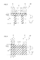
- piezoelectric element layers 2 are formed on the upper surface (along arrow Z1) of the Si substrate 1, as shown in Fig. 3 .
- the inner driving portions 14a and 14b are formed to be convexly and concavely deformed in a direction Z with respect to the fixed portions 15a and 15b serving as fixed ends respectively upon voltage application, as shown in Fig. 1 .
- the A-directional optical scanning portion 10 is formed to be capable of inclining the mirror 11 on the axis 300 (see Fig. 2 ) along arrow A1 or A2 by deforming the inner driving portions 14a and 14b in the directions opposite to each other.
- the A-directional optical scanning portion 10 is formed to swing the mirror 11 on the axis 300 and to optically scan the object by repeating the deforming operation.
- the piezoelectric element layers 2 are described later in more detail.
- the thickness W1 of the frame body 16 in the vertical direction is larger than the thickness W2 of the inner driving portions 14a and 14b in the vertical direction, and also larger than the thickness W3 of the mirror 11, the torsion bars 12a and 12b (see Fig. 1 ), the bars 13a and 13b (see Fig. 1 ) and the fixing portions 15a and 15b in the vertical direction.
- Both of the rotating shafts 30 and 31 are formed on the axis 400 to extend in a direction X along the axis 400, as shown in Fig. 2 .
- the rotating shaft 30 is connected with the frame body 16 of the A-directional optical scanning portion 10 along arrow X1, and connected with a driving unit 40, described later, of the B-directional optical scanning portion 20 along arrow X1.
- the rotating shaft 31 is connected with the frame body 16 of the A-directional optical scanning portion 10 along arrow X1, and connected with a driving unit 50, described later, of the B-directional optical scanning portion 20 along arrow X2.
- both of the rotating shafts 30 and 31 are formed as shafts for the B-directional optical scanning portion 20 swinging the A-directional optical scanning portion 10 (mirror 11) on the axis 400 along arrows B1 and B2.
- the rotating shafts 30 and 31 are examples of the "shaft portion" in the present invention.
- the rotating shafts 30 and 31 formed on the sides of the A-directional optical scanning portion 10 along arrows X1 and X2 respectively are formed to be substantially point-symmetrical to each other with respect to the center R of the mirror 11.
- the rotating shaft 31 is arranged in such positional relation that the same substantially overlaps with the rotating shaft 30 when rotated by 180° on the center R of the mirror 11.
- the B-directional optical scanning portion 20 includes the driving units 40 and 50 formed on the sides of the A-directional optical scanning portion 10 along arrows X1 and X2 respectively, as shown in Fig. 2 .
- the driving units 40 and 50 are arranged to hold the A-directional optical scanning portion 10 therebetween in the direction X.
- the driving units 40 and 50 are examples of the "driving portion" in the present invention.
- the driving unit 40 includes five driving portions 41, 42, 43, 44 and 45 and four coupling support portions 46, 47, 48 and 49.
- the driving unit 50 includes five driving portions 51, 52, 53, 54 and 55 and four coupling support portions 56, 57, 58 and 59.
- the driving portions 41, 42, 43, 44 and 45 and 51, 52, 53, 54 and 55 are formed to be deformed upon voltage application, while the coupling support portions 46, 47, 48 and 49 and 56, 57, 58 and 59 are formed to remain substantially undeformed.
- the driving unit 40 is connected with the fixing portion 32, while the driving unit 50 is connected with the fixing portion 33.
- the fixing portion 32 includes a support portion 32a arranged between the frame body 16 of the A-directional optical scanning portion 10 and the driving unit 40, a body portion 32b arranged on a position opposed to a side portion of the A-directional optical scanning portion 10 extending in the direction X along arrow Y1 and a fixing portion connecting portion 32c, connecting the support portion 32a and the body portion 32b with each other, arranged between the frame body 16 of the A-directional optical scanning portion 10 and the driving unit 40.
- the fixing portion 33 includes a support portion 33a arranged between the frame body 16 of the A-directional optical scanning portion 10 and the driving unit 50, a body portion 33b arranged on a position opposed to another side portion of the A-directional optical scanning portion 10 extending in the direction X along arrow Y2 and a fixing portion connecting portion 33c, connecting the support portion 33a and the body portion 33b with each other, arranged between the frame body 16 of the A-directional optical scanning portion 10 and the driving unit 50.
- the support portions 32a and 33a are examples of the "fixed end support portion" in the present invention.
- the body portions 32b and 33b of the fixing portions 32 and 33 are arranged to hold the A-directional optical scanning portion 10 therebetween in the direction Y. Further, both of the fixing portions 32 and 33 are formed on positions where the same are held between the driving units 40 and 50 in the direction X.
- the driving units 40 and 50 formed on the sides of the A-directional optical scanning portion 10 along arrows X1 and X2 respectively are similar in structure to each other, and formed to be substantially point-symmetrical to each other with respect to the center R of the mirror 11.
- the driving portions 51, 52, 53, 54 and 55 and the coupling support portions 56, 57, 58 and 59 of the driving unit 50 are arranged in such positional relation that the same substantially overlap with the driving portions 41, 42, 43, 44 an 45 and the coupling support portions 46, 47, 48 and 49 respectively when rotated by 180° on the center R of the mirror 11.
- the rotating shafts 30 and 31 formed on the sides of the A-directional optical scanning portion 10 along arrows X1 and X2 respectively are substantially similar in structure to each other, and formed to be substantially point-symmetrical to each other with respect to the center R of the mirror 11.
- the fixing portions 32 and 33 formed on the sides of the A-directional optical scanning portion 10 along arrows Y1 and Y2 respectively are also similar in structure to each other, and formed to be substantially point-symmetrical to each other with respect to the center R of the mirror 11.
- An outer end portion of the body portion 32b of the fixing portion 32 along arrow Y1 and outer end portions of the driving units 40 and 50 along arrow Y1 are formed to substantially coincide with each other as viewed from the direction X, while an outer end portion of the body portion 33b of the fixing portion 33 along arrow Y2 and outer end portions of the driving units 40 and 50 along arrow Y2 are formed to substantially coincide with each other as viewed from the direction X.
- the driving portions 41, 42, 43, 44 and 45 of the driving unit 40 are formed to extend in the direction Y orthogonal to the axis 400 together.
- the coupling support portions 46, 47, 48 and 49 are formed to extend in the direction X along the axis 400 together.
- the driving unit 40 is so formed that the four coupling support portions 46, 47, 48 and 49 connect the five driving portions 41, 42, 43, 44 and 45 with each other to constitute one driving portion.
- the driving unit 40 is so formed that an end portion, serving as a first end portion of the driving unit 40, of the driving portion 41 along arrow Y1 forms a free end S1 while another end portion, serving as a second end portion of the driving unit 40, of the driving portion 45 along arrow Y2 forms a fixed end S2.
- the driving portion 41 is an example of the "first driving portion” in the present invention
- the driving portion 45 is an example of the "second driving portion” in the present invention.
- the driving portions 42, 43 and 44 are examples of the "third driving portion" in the present invention.
- the coupling support portion 46 is an example of the "first connecting portion” in the present invention
- the coupling support portion 49 is an example of the “second connecting portion” in the present invention
- the coupling support portions 47 and 48 are examples of the "third connecting portion” in the present invention.
- the driving portions 41 and 45 are arranged to substantially overlap with each other as viewed from the direction Y and formed at a prescribed interval in the direction Y, as shown in Fig. 2 .
- the driving portions 42, 43 and 44 are formed on the side (along arrow X1) of the driving portions 41 and 45 opposite to the A-directional optical scanning portion 10 successively from the side (along arrow X2) of the driving portions 41 and 45 toward the side along arrow X1 at prescribed intervals in the direction X.
- the driving portion 41 provided on the side (along arrow X2) of the driving unit 40 closer to the A-directional optical scanning portion 10 is formed to extend from a substantially central portion of the driving unit 40 in the direction Y to an end portion S3 along arrow Y2.
- This driving portion 41 is connected with the side of the rotating shaft 30 along arrow X1 on the free end S1 along arrow Y1, and connected with the side of the coupling support portion 46 along arrow X2 on the end portion S3 along arrow Y2.
- Both of the driving portions 42 and 43 held between the driving portions 41 and 45 and the driving portion 44 are formed to extend from an end portion of the driving unit 40 along arrow Y1 to portions close to another end portion along arrow Y2.
- the driving portion 42 is connected with a side of the coupling support portion 46 along arrow X1 on an end portion S4 along arrow Y2, and connected with a side of the coupling support portion 47 along arrow X2 on an end portion S5 along arrow Y1.
- the driving portion 42 is connected with the driving portion 41 in a manner folded through the coupling support portion 46, and connected with the driving portion 43 in a manner folded through the coupling support portion 47.
- the driving portion 43 is connected with a side of the coupling support portion 47 along arrow X1 on an end portion S6 along arrow Y1, and connected with a side of the coupling support portion 48 along arrow X2 on an end portion S7 along arrow Y2.
- the driving portion 43 is connected with the driving portion 42 in a manner folded through the coupling support portion 47, and connected with the driving portion 44 in a manner folded through the coupling support portion 48.
- the driving portion 44 provided on the side (along arrow X1) of the driving unit 40 opposite to the A-directional optical scanning portion 10 is formed to extend from the end portion of the driving unit 40 along arrow Y1 to another end portion along arrow Y2.
- This driving portion 44 is connected with a side of the coupling support portion 48 along arrow X1 on an end portion S8 along arrow Y2, and connected with a side of the coupling support portion 49 along arrow X1 on an end portion S9 along arrow Y1.
- the driving portion 44 is connected with the driving portion 43 in a manner folded through the coupling support portion 48, and connected with the driving portion 45 in a manner folded through the coupling support portion 49.
- the driving portion 45 provided on the side (along arrow X2) of the driving unit 40 closer to the A-directional optical scanning portion 10 is formed to extend from the end portion of the driving unit 40 along arrow Y1 to a portion close to the substantially central portion in the direction Y.
- the driving portion 45 is connected with a side of the coupling support portion 49 along arrow X2 on an end portion S10 along arrow Y1, and connected with the support portion 32a of the fixing portion 32 formed on the side of the driving unit 40 along arrow X2 on the fixed end S2 along arrow Y2.
- the support portion 32a fixes the fixed end S2 of the driving unit 40 on the side (along arrow X2) closer to the A-directional optical scanning portion 10 in the vicinity of the rotating shaft 30 located in the vicinity of the substantially central portion in the direction Y.
- the driving portions 42, 43 and 44 extend beyond the driving portions 41 and 45 in the direction Y, to extend over the driving portions 41 and 45.
- both of the free end S1 and the fixed end S2 of the driving unit 40 are formed on the side (along arrow X2) of the driving unit 40 closer to the A-directional optical scanning portion 10, as hereinabove described. Further, an end surface of the free end S1 of the driving portion 41 along arrow Y1 and an end surface of the fixed end S2 of the driving portion 45 along arrow Y2 are arranged to substantially overlap with each other as viewed fro the direction Y. In other words, the end surface of the free end S1 of the driving unit 40 along arrow Y1 and the end surface of the fixed end S2 along arrow Y2 are arranged to be opposed to each other in the direction Y.
- the vibrating mirror element 100 is so formed that the length L1 of the support portion 32a of the fixing portion 32 in the direction X is smaller than the length L2 of the rotating shaft 30 in the direction X. More specifically, the vibrating mirror element 100 is so formed that the length L1 of the support portion 32a from a side surface closer to the A-directional optical scanning portion 10 (along arrow X2) to a side of the fixed end S2 along arrow X1 is smaller than the length L2 from a portion connecting the frame body 16 and the rotating shaft 30 with each other to a side of the free end S1 along arrow X1.
- piezoelectric element layers 2 are formed on the upper surface (along arrow Z1) of the Si substrate 1 in the driving portions 41 to 45, similarly to the inner driving portions 14a and 14b of the A-directional optical scanning portion 10.
- the driving portions 41 to 45 are formed to be concavely or convexly deformed in the direction Z upon voltage application.
- SiO 2 layers 3, Si layers 4 and mask layers 5 are provided on the lower surface (along arrow Z2) of the Si substrate 1 from the side along arrow Z1 toward the side along arrow Z2 in the rotating shaft 30 (see Fig. 3 ), the coupling support portions 46 to 49 (see Figs. 4 to 6 ) and the fixing portion 32 (see Figs. 5 and 6 ), similarly to the frame body 16 of the A-directional optical scanning portion 10.
- the thickness W1 of the rotating shaft 30, the coupling support portions 46 to 49 and the fixing portion 32 in the vertical direction (direction Z) is larger than the thickness W2 of the driving portions 41 to 45 (excluding the free end S1, the fixed end S2 and the end portions S3 to S10) in the vertical direction.
- piezoelectric element layers 2 are formed on the upper surface (along arrow Z1) of the Si substrate 1, while SiO 2 layers 3, Si layers 4 and mask layers 5 are provided on the lower surface (along arrow Z2) of the Si substrate 1 from the side along arrow Z1 toward the side along arrow Z2.
- the thickness W4 of the free end S1, the fixed end S2 and the end portions S3 to S10 in the vertical direction is larger than the thickness W2 of the driving portions 41 to 45 (excluding the free end S1, the fixed end S2 and the end portions S3 to S10) in the vertical direction.
- the coupling support portions 46 and 49 are examples of the first connecting portion" and the “second connecting portion” in the present invention respectively.
- the coupling support portions 47 and 48 are examples of the "fourth connecting portion” and the "third connecting portion” in the present invention respectively.
- Each piezoelectric element layer 2 has a structure obtained by stacking a lower electrode 20, a piezoelectric body 21 and an upper electrode 22 from the side (along arrow Z2) closer to the Si substrate 1, as shown in Fig. 8 .
- the lower electrode 20, made of Ti or Pt, is formed on the overall upper surface of the Si substrate 1.
- wiring on the lower electrode 20 of the piezoelectric element layer 2 can be performed with respect to an arbitrary portion of the Si substrate 1.
- the thickness of the lower electrode 20 in the vertical direction is sufficiently small with respect to the Si substrate 1, and hence the drawings other than Fig. 8 omit illustration of the lower electrode 20 formed on the upper surface of the Si substrate 1.
- the upper electrode 22 is made of a conductive metallic material such as Al, Cr, Cu, Au or Pt.
- the driving portions 41 to 45 are formed to be deformed and to drive the A-directional optical scanning portion 10 upon voltage application. Further, the driving portions 41 to 45 are so formed that a voltage applied to the driving portions 41, 43 and 45 and that applied to the driving portions 42 and 44 are out of phase with each other.
- the driving portion 45 of the driving unit 40 has a cantilever structure having the fixed end S2 and the end portion S10 serving as a free end, as shown in Figs. 1 and 2 .
- the driving portion 45 is formed to be deformed in a warping manner thereby displacing the end portion S10 in the direction Z (see Fig. 1 ) and inclining the same when driving the A-directional optical scanning portion 10.
- the fixed end S2 remains undisplaced when the driving portion 45 drives the A-directional optical scanning portion 10.
- the driving portion 45 is so formed that the end portion S10 inclines with respect to the fixed end S2.
- the coupling support portion 49 connecting the driving portions 45 and 44 with each other is formed to be substantially undeformed, thereby supporting the end portion S9 while maintaining the inclination of the end portion S10.
- the driving portion 44 has a cantilever structure having the end portion S9 serving as a fixed end and the end portion S8 serving as a free end.
- the end portion S8 inclines with respect to the end portion S9.
- the coupling support portion 48 is formed to support the end portion S7 while maintaining the inclination of the end portion S8.
- the driving portion 43 has a cantilever structure having the end portion S7 serving as a fixed end and the end portion S6 serving as a free end. Thus, the driving portion 43 is so formed that the end portion S7 inclines with respect to the end portion S6.
- the coupling support portion 47 is formed to support the end portion S5 while maintaining the inclination of the end portion S6.
- the driving portion 42 has a cantilever structure having the end portion S5 serving as a fixed end and the end portion S4 serving as a free end.
- the driving portion 42 is so formed that the end portion S5 inclines with respect to the end portion S4.
- the coupling support portion 46 is formed to support the end portion S3 while maintaining the inclination of the end portion S4.
- the driving portion 41 has a cantilever structure having the end portion S3 serving as a fixed end and the free end S1.
- the driving portion 41 is so formed that the free end S1 inclines with respect to the end portion S3. Consequently, the driving portion 41 is so formed that the free end S1 inclines the rotating shaft 30 and the A-directional optical scanning portion 10 while accumulating the inclinations of the driving portions 41 to 45.
- the B-directional optical scanning portion 20 is so formed that voltages in phase with each other are applied to the driving portions 41, 43 and 45 of the driving unit 40 and the driving portions 52 and 54 of the driving unit 50. Further, the B-directional optical scanning portion 20 is so formed that voltages in phase with each other are applied to the driving portions 42 and 44 of the driving unit 40 and the driving portions 51, 53 and 55 of the driving unit 50. In addition, the B-directional optical scanning portion 20 is so formed that voltages out of phase with each other are applied to the driving portions 41, 43, 45, 52 and 54 and the driving portions 42, 44, 51, 53 and 55. Consequently, the B-directional optical scanning portion 20 is so formed that the driving units 40 and 50 drive the A-directional optical scanning portion 10 reversely to each other.
- the driving units 40 and 50 formed to be substantially point-symmetrical to each other with respect to the center R of the mirror 11, can incline the rotating shafts 30 and 31 connected therewith in the same direction on the axis 400.
- the driving units 40 and 50 are formed to be capable of rotating the A-directional optical scanning portion 10 connected with the rotating shafts 30 and 31 on the axis 400 along arrow B1 or B2 (see Fig. 1 ).
- a driving operation of the B-directional optical scanning portion 20 of the vibrating mirror element 100 according to the embodiment of the present invention is now described with reference to Figs. 1, 2 and 9 to 12 .
- a voltage for contracting the upper surface side (along arrow Z1) of the piezoelectric element layers 2 beyond the lower surface side (along arrow Z2) is applied to the driving portions 41, 43 and 45 of the driving unit 40 and the driving portions 52 and 54 of the driving unit 50, as shown in Fig. 9 .
- the driving portions 41, 43 and 45 are so deformed that the free end S1 and the end portions S6 and S10 incline upward (along arrow Z1) with respect to the end portions S3 and S7 and the fixed end S2 respectively in the driving unit 40, as shown in Fig. 10 .
- the driving portions 42 and 44 are so deformed that the end portions S4 and S8 incline downward (along arrow Z2) with respect to the end portions S5 and S9 respectively. Consequently, the rotating shaft 30 connected with the free end S1 inclines the A-directional optical scanning portion 10 so that the side along arrow Y1 is located upward (along arrow Z1) beyond the side along arrow Y2 while accumulating the inclinations of the driving portions 41 to 45.
- the driving unit 50 drives the A-directional optical scanning portion 10 reversely to the driving unit 40, whereby the rotating shaft 31 inclines the A-directional optical scanning portion 10 so that the side along arrow Y1 is located upward (along arrow Z1) beyond the side along arrow Y1 while accumulating the inclinations of the driving portions 51 to 55, as shown in Fig. 11 .
- the A-directional optical scanning portion 10 is rotated on the axis 400 along arrow B1.
- a voltage for contracting the lower surface side (along arrow Z2) of the piezoelectric element layers 2 beyond the upper surface side (along arrow Z1) is applied to the driving portions 41, 43 and 45 of the driving unit 40 and the driving portions 52 and 54 of the driving unit 50, as shown in Fig. 12 .
- the driving unit 40 deforms reversely to the state shown in Figs. 9 and 10 , whereby the rotating shaft 30 so inclines the A-directional optical scanning portion 10 that the side along arrow Y1 is located downward (along arrow Z1) beyond the side along arrow Y2 while accumulating the inclinations of the driving portions 41 to 45.
- the driving unit 50 drives the A-directional optical scanning portion 10 reversely to the driving unit 40, whereby the rotating shaft 31 inclines the A-directional optical scanning portion 10 so that the side along arrow Y1 is located downward (along arrow Z1) beyond the side along arrow Y2 while accumulating the inclinations of the driving portions 51 to 55.
- the A-directional optical scanning portion 10 is rotated on the axis 400 along arrow B2.
- the driving units 40 and 50 swing the A-directional optical scanning portion 10 on the axis 400 by repeating the aforementioned driving operations.
- the driving units 40 and 50 can swing the mirror 11 on the axis 300 while swinging the same on the axis 400 by driving the A-directional optical scanning portion 10 simultaneously with the B-directional optical scanning portion 20.
- Steps of manufacturing the vibrating mirror element 100 according to the embodiment of the present invention are now described with reference to Figs. 8 , 13 and 14 .
- a motherboard is prepared by providing an SiO 2 layer 3 and an Si layer 4 on the lower surface (along arrow Z2) of the Si substrate 1 in this order, as shown in Fig. 13 .
- lower electrodes 20 and piezoelectric bodies 21 are successively formed on the overall upper surface (along arrow Z1) of the motherboard by sputtering or the like.
- upper electrodes 22 are formed on the upper surfaces of the piezoelectric bodies 21 corresponding to the inner driving portions 14a and 14b (see Fig. 3 ), the driving portions 41, 42, 43, 44, 45, 51, 52, 53, 54 and 55 (see Fig. 3 ) by vapor deposition or the like.
- the piezoelectric element layers 2 are formed on the inner driving portions 14a and 14b and the driving portions 41 to 45 and 51 to 55.
- resist patterns (not shown) are formed on positions corresponding to the inner driving portions 14a and 14b and the driving portions 41 to 45 and 51 to 55, and wet etching or the like is thereafter performed through the resist patterns serving as masks, thereby removing portions of the piezoelectric bodies 21 formed on positions other than those corresponding to the inner driving portions 14a and 14b and the driving portions 41 to 45 and 51 to 55.
- mask layers 5 made of Al, Cr or Cu are formed on positions of the lower surface (along arrow Z2) of the motherboard (Si layer 4) corresponding to the frame body 16, the rotating shafts 30 and 31, the coupling support portions 46 to 49 and 56 to 59 and the fixing portions 32 and 33 by vapor deposition or the like.
- a resist pattern (not shown) is formed on a position corresponding to the vibrating mirror element 100 by photolithography and thereafter employed as a mask for removing portions of the lower electrodes 20 formed on positions other than that corresponding to the vibrating mirror element 100 by reactive ion etching (RIE) or the like. Thereafter portions of the Si substrate 1 formed on positions other than that corresponding to the vibrating mirror element 100 are removed by reactive ion etching (RIE) or the like.
- RIE reactive ion etching
- portions of the Si layer 4 formed on positions other than those corresponding to the frame body 16, the rotating shafts 30 and 31, the coupling support portions 46 to 49 and 56 to 59 and the fixing portions 32 and 33 are removed through mask layers 5 by reactive ion etching (RIE) or the like, as shown in Fig. 14 .
- RIE reactive ion etching
- portions of the Si layer 4 formed on positions corresponding to the free end S1, the fixed end S2 and the end portions S3 to S10 of the driving unit 40 and those corresponding to the free end, the fixed end and the end portions of the driving unit 50 are mot removed.
- portions of the SiO 2 layer 3 formed on the positions other than that corresponding to the vibrating mirror element 100 are removed by reactive ion etching (RIE) or the like.
- RIE reactive ion etching
- the support portion 32a fixes the fixed end S2 of the driving unit 40 on the side (along arrow X2) closer to the A-directional optical scanning portion 10, whereby the fixed end S2 is not separated from the A-directional optical scanning portion 10, but can be fixed between the A-directional optical scanning portion 10 and the driving unit 40 or around the A-directional optical scanning portion 10.
- the vibrating mirror element 100 can be inhibited from size increase in the extensional direction (direction X) of the axis 400.
- the support portion 32a fixes the fixed end S2 of the driving unit 40 in the vicinity of the rotating shaft 30 positioned in the vicinity of the substantially central portion in the direction Y, whereby the free end S1 and the fixed end S2 are not separated from each other.
- the free end S1 can be inhibited from inclining with respect to the fixed end S2, whereby the A-directional optical scanning portion 10 connected with the free end S1 can also be inhibited from inclining with respect to the fixed end S2 when the driving unit 40 does not drive the A-directional optical scanning portion 10.
- the length L1 of the support portion 32a in the direction X is set smaller than the length L2 of the rotating shaft 30 in the direction X, whereby the support portion 32a can be easily arranged between the A-directional optical scanning portion 10 and the driving unit 40. Further, the support portion 32a is so arranged between the A-directional optical scanning portion 10 and the driving unit 40 that the vibrating mirror element 100 can be inhibited from size increase in the direction X.
- the fixed portion 32 is formed to include the body portion 32b arranged on the position opposed to the side portion of the A-directional optical scanning portion 10 extending in the direction X along arrow Y1 and the fixing portion connecting portion 32c, connecting the support portion 32a and the body portion 32b with each other, arranged between the frame body 16 of the A-directional optical scanning portion 10 and the driving unit 40.
- the fixing portion 33 is formed to include the body portion 33b arranged on the position opposed to the other side portion of the A-directional optical scanning portion 10 extending in the direction X along arrow Y2 and the fixing portion connecting portion 33c, connecting the support portion 33a and the body portion 33b with each other, arranged between the frame body 16 of the A-directional optical scanning portion 10 and the driving unit 50.
- the body portion 32a (33b) and the support portion 32a (33a) are so connected with each other through the fixing portion connecting portion 32c (33c) arranged between the A-directional optical scanning portion 10 and the driving unit 40 (50) that the body portion 32a (33b) may not be arranged between the A-directional optical scanning portion 10 and the driving unit 40 (50). Therefore, the space between the A-directional optical scanning portion 10 and the driving unit 40 (50) can be reduced, whereby the vibrating mirror element 100 can be inhibited from size increase in the extensional direction of the axis 400.
- the outer end portion of the body portion 32b of the fixing portion 32 along arrow Y1 and those of the driving units 40 and 50 along arrow Y1 substantially coincide with each other as viewed from the direction X while the outer end portion of the body portion 33b of the fixing portion 33 along arrow Y2 and those of the driving units 40 and 50 along arrow Y2 substantially coincide with each other as viewed from the direction X so that the fixed portions 32 and 33 do not protrude beyond the driving units 40 and 50 in the direction Y, whereby the vibrating mirror element 100 can be inhibited from size increase in the direction Y.
- the fixing portions 32 and 33 can reliably fix the fixed end S2.
- the end surface of the free end S1 of the driving portion 41 along arrow Y1 and that of the fixed end S2 of the driving portion 45 along arrow Y2 are arranged to substantially overlap with each other as viewed from the direction Y, whereby the fixed end S2 can be easily arranged on the side (along arrow X2) of the driving unit 40 closer to the A-directional optical scanning portion 10 and in the vicinity of the rotating shaft 30 connected with the free end S1.
- the end surface of the free end S1 along arrow Y1 and that of the fixed end S2 along arrow Y2 are opposed to each other, whereby the positions of the driving portions 41 and 45 can be inhibited from remarkably deviating from each other in the direction X.
- the vibrating mirror element 100 can be inhibited from size increase in the direction X.
- the fixed ends of the driving units 40 and 50 are fixed on the side (along arrow X2) closer to the A-directional optical scanning portion 10 also in the case where the driving unit 40 and the rotating shaft 30 are arranged on the side of the A-directional optical scanning portion 10 along arrow X1 and the driving unit 50 and the rotating shaft 31 are formed on the side of the A-directional optical scanning portion 10 along arrow X2, whereby the vibrating mirror element 100 can be inhibited from size increase in the direction X.
- both of the fixing portions 32 and 33 are formed on the positions held between the driving units 40 and 50 in the direction X so that the fixing portions 32 and 33 are not arranged on the sides (along arrows X1 and X2) of the driving units 40 and 50 opposite to the A-directional optical scanning portion 10 in the direction X, whereby the vibrating mirror element 100 can be inhibited from size increase in the direction X.
- the body portions 32b and 33b of the fixing portions 32 and 33 are arranged to hold the A-directional optical scanning portion 10 therebetween in the direction Y so that the different fixing portions 32 and 33 can fix the fixed ends S2 of the driving units 40 and 50 respectively, whereby the fixed ends S2 can be more reliably fixed to the fixing portions 32 and 33.
- the body portions 32b and 33b of the fixing portions 32 and 33 may not be arranged between the A-directional optical scanning portion 10 and the driving units 40 and 50, whereby the spaces between the A-directional optical scanning portion 10 and the driving units 40 and 50 can be reduced.
- the driving unit 40 is so formed that the four coupling support portions 46, 47, 48 and 49 connect the five driving portions 41, 42, 43, 44 and 45 with each other to constitute one driving portion, whereby the end portion of the driving portion 41 along arrow Y1 serving as the first end portion of the driving unit 40 forms the free end S1 while the end portion of the driving portion 45 along arrow Y2 serving as the second end portion of the driving unit 40 forms the fixed end S2.
- the driving portions 42 and 44 are connected with the driving portions 41 and 45 through the coupling support portions 46 and 49 respectively.
- the driving portions 41 and 45 can be connected with each other through the coupling support portion 46, the driving portions 42, 43 and 44 and the coupling support portion 49.
- inclinations of the driving portions 45, 42, 43, 44 and 41 by deformation can be transmitted to the A-directional optical scanning portion 10 through the rotating shaft 30, whereby the A-directional optical scanning portion 10 can be swung with a large inclination.
- the thickness W1 of the coupling support portions 46 to 49 in the vertical direction is set larger than the thickness W2 of the driving portions 41 to 45 in the vertical direction while the thickness W4 of the free end S1, the fixed end S2 and the end portions S3 to S10 in the vertical direction is set larger than the thickness W2 of the driving portions 41 to 45 in the vertical direction so that the coupling support portions 46 to 49 can be inhibited from deformation and inclination, whereby the connected driving portions 41 to 44 can be deformed to incline while substantially maintaining the inclinations in the deformed driving portions 42 to 45.
- the inclinations of the driving portions 41 to 45 can be accumulated, whereby the overall driving unit 40 can be more largely deformed.
- the A-directional optical scanning portion 10 can be swung with a larger inclination.
- the thickness W1 of the coupling support portions 46 to 49 in the vertical direction (direction Z) is so increased that the lengths of the coupling support portions 46 to 49 in the direction (direction Y) orthogonal to the axis 400 can be reduced while maintaining rigidity of the coupling support portions 46 to 49.
- the driving portions 41 to 45 can be more lengthened in the direction Y, whereby driving force thereof can be increased. Consequently, the A-directional optical scanning portion 10 can be more inclined.
- the driving portions 42, 43 and 44 are formed on the side (along arrow X1) of the driving portions 41 and 45 opposite to the A-directional optical scanning portion 10 successively from the side (along arrow X2) of the driving portions 41 and 45 toward the side along arrow X1 at the prescribed intervals in the direction X, whereby the free end S1 of the driving portion 41 and the rotating shaft 30 can be positioned closer to each other while the fixed end S2 of the driving portion 45 can be easily fixed in the vicinity of the rotating shaft 30.
- the vibrating mirror element 100 can be inhibited from size increase in the direction X.
- the driving portions 42, 43 and 44 are formed to extend beyond the driving portions 41 and 45 in the direction Y to extend over the driving portions 41 and 45, whereby the driving portions 41 and 45 can be reduced in size to be approximated to each other in the direction orthogonal to the axis 400.
- the free end S1 of the driving portion 41 and the rotating shaft 30 can be easily connected with each other, and the fixed end S2 of the driving portion 45 can be easily fixed in the vicinity of the rotating shaft 30.
- the driving portions 42, 43 and 44 are so increased in size that driving force (inclinations) thereof can be increased.
- the driving portion 42 is connected with the driving portion 41 in the manner folded through the coupling support portion 46, and connected with the driving portion 43 in the manner folded through the coupling support portion 47.
- the driving portion 43 is connected with the driving portion 42 in the manner folded through the coupling support portion 47, and connected with the driving portion 44 in the manner folded through the coupling support portion 48.
- the driving portion 44 is connected with the driving portion 43 in the manner folded through the coupling support portion 48, and connected with the driving portion 45 in the manner folded through the coupling support portion 49.
- the inclination of the driving portion 45 can be transmitted to the driving portion 44, and the inclinations of the driving portions 42, 43 and 44 can be accumulated to the inclination of the driving portion 45 and transmitted to the driving portion 41. Therefore, the inclinations of the driving portions 45, 42, 43, 44 and 41 can be accumulated and transmitted to the A-directional optical scanning portion 10 through the rotating shaft 30, whereby the A-directional optical scanning portion 10 can be swung with a larger inclination.
- the driving units 40 and 50 provided on the sides of the A-directional optical scanning portion 10 along arrows X1 and X2 respectively are formed to be substantially point-symmetrical to each other with respect to the center R of the mirror 11 while the rotating shafts 30 and 31 provided on the sides of the A-directional optical scanning portion 10 along arrows X1 and X2 respectively are formed to be substantially point-symmetrical to each other with respect to the center R of the mirror 11.
- the substantially point-symmetrical driving units 40 and 50 and the substantially point-symmetrical rotating shafts 30 and 31 can support the A-directional optical scanning portion 10, whereby the A-directional optical scanning portion 10 can be stably supported, and can be inhibited from rotating on a rotational axis deviating from the axis 400.
- the A-directional optical scanning portion 10, the B-directional optical scanning portion 20 including the driving units 40 and 50, the rotating shafts 30 and 31 and the fixing portions 32 and 33 are integrally formed on the common Si substrate 1 so that the A-directional optical scanning portion 10, the driving units 40 and 50, the rotating shafts 30 and 31 and the fixing portions 32 and 33 may not be bonded to each other, whereby joint portions therebetween can be increased in strength, and the manufacturing steps for the vibrating mirror element 100 can be simplified by omitting steps for bonding.
- the A-directional optical scanning portion 10 includes the mirror 11 and the inner driving portions 14a and 14b capable of inclining the mirror 11 on the axis 300 along arrow A1 or A2, whereby the vibrating mirror element 100 can two-dimensionally optically scan the object with the mirror 11.
- the A-directional optical scanning portion 10 is formed to resonantly drive the mirror 11 at the resonance frequency of about 30 kHz while the B-directional optical scanning portion 20 is formed to nonresonantly drive the mirror 11 at the frequency of about 60 Hz, whereby the vibrating mirror element 100 can two-dimensionally optically scan the object by rotating the mirror 11 on the axis 300 at a speed higher than that for rotating the A-directional optical scanning portion 10 on the axis 400.
- the vibrating mirror element 100 is so formed that the driving units 40 and 50 similar in structure to each other are formed to be substantially point-symmetrical to each other with respect to the center R of the mirror 11 and the fixing portions 32 and 33 similar in structure to each other are also formed to be substantially point-symmetrical to each other with respect to the center R of the mirror 11 in the aforementioned embodiment, the present invention is not restricted to this.
- driving units 40 and 250 similar in structure to each other may alternatively be formed to be line-symmetrical to each other with respect to a symmetry axis 500 passing through the center R of a mirror 11 and extending in a direction Y, as in a vibrating mirror element 200 according to a modification of the embodiment shown in Fig. 15 .
- a fixing portion 232 fixing fixed ends S2 and S22 of the driving units 40 and 250 may be provided on one side (along arrow Y1) of an A-directional optical scanning portion 10 in the direction Y.
- no fixing portion may be separately provided on a side of the A-directional optical scanning portion 10 along arrow Y2.
- the fixing portion 232 provided on a side of the vibrating mirror element 200 along arrow Y1 is formed to be line-symmetrical with respect to the symmetry axis 500, and provided with support portions 232a and 232d on both end portions of a body portion 232b, formed on a side along arrow Y1, in a direction X.
- the support portion 232a provided on a side (along arrow X1) closer to the driving unit 40 is formed to fix the fixed end S2 of the driving unit 40 in the vicinity of a rotating shaft 30.
- the support portion 232d provided on a side (along arrow X2) closer to the driving unit 250 is formed to fix the fixed end S22 of the driving unit 250 in the vicinity of a rotating shaft 31.
- the vibrating mirror element 200 can be inhibited from size increase in the direction X, while the A-directional optical scanning portion 10 can be inhibited from inclining with respect to the fixed ends S2 and S22 in a state not driven by the driving units 40 and 250.
- the substantially line-symmetrical driving units 40 and 250 and the substantially line-symmetrical rotating shafts 30 and 31 can support the A-directional optical scanning portion 10, whereby the A-directional optical scanning portion 10 can be stably supported, and can be inhibited from rotating on a rotating axis deviating from an axis 400.
- the symmetry axis 500 is an example of the "centerline" in the present invention.
- the vibrating mirror element may alternatively be provided with one driving unit, one rotating shaft and one fixing portion.
- the present invention is not restricted to this.
- part of the end surface of the free end and part of the end surface of the fixed end may alternatively be arranged to overlap with each other as viewed from the direction Y.
- the end surfaces of the free end and the fixed end may simply be opposed to each other as viewed from the direction Y.
- the piezoelectric body 21 is made of lead zirconate titanate (PZT) in the aforementioned embodiment, the present invention is not restricted to this.
- the piezoelectric body may alternatively be made of a piezoelectric material, other than PZT, consisting of an oxide mainly composed of lead, titanium and/or zirconium or another piezoelectric material.
- the piezoelectric body may be made of a piezoelectric material such as zinc oxide (ZnO), lead lanthanate zirconate titanate ((Pb,La) (Zr,Ti)O 3 ), potassium niobate (KnBO 3 ) or sodium niobate (NaNbO 3 ), for example.
- both of the free end and the fixed of the driving unit may simply be formed on the side of the driving unit closer to the A-directional optical scanning unit, and the driving unit may be so formed that two coupling support portions connect three driving portions with each other, for example.
- the thickness W1 of the coupling support portions 46 to 49 in the vertical direction is set larger than the thickness W2 of the driving portions 41 to 45 (excluding the free end S1, the fixed end S2 and the end portions S3 to S10) in the vertical direction and the thickness W4 of the fixed end S2 and the end portions S3 to S10 in the vertical direction is set larger than the thickness W2 of the driving portions 41 to 45 (excluding the free end S1, the fixed end S2 and the end portions S3 to S10) in the vertical direction in the aforementioned embodiment
- the present invention is not restricted to this.
- the thickness of the driving portions in the vertical direction may alternatively be set substantially equal to that of the end portions in the vertical direction.
- the inner driving portions 14a and 14b and the driving portions 41 to 45 and 51 to 55 include the piezoelectric element layers 2 each having the structure obtained by stacking the lower electrode 20, the piezoelectric body 21 and the upper electrode 22 in the aforementioned embodiment, the present invention is not restricted to this.
- the inner driving portions and the driving portions may alternatively be formed to be driven by drivers other than the piezoelectric elements.
- the inner driving portions and the driving portions may be driven by drivers, made of an elastomer, held between electrodes. In this case, a voltage is so applied between the electrodes that the electrodes attract each other thereby compressing and deforming the drivers made of the elastomer.
- the vibrating mirror element 100 including the A-directional optical scanning portion 10 and the B-directional optical scanning portion 20 is formed to two-dimensionally optically scan the object in the aforementioned embodiment
- the present invention is not restricted to this.
- the A-directional optical scanning portion may alternatively consist of only a mirror not to have inner driving portions, so that the vibrating mirror element is formed to only one-dimensionally optically scan the object.
Landscapes
- Physics & Mathematics (AREA)
- General Physics & Mathematics (AREA)
- Optics & Photonics (AREA)
- Mechanical Light Control Or Optical Switches (AREA)
- Mechanical Optical Scanning Systems (AREA)
- Micromachines (AREA)
Abstract
This vibrating mirror element (100) includes a mirror portion (10) swingable on a first axis (400), a driving portion (40, 50), including a free end (S1) and a fixed end (S2), for swinging the mirror portion by deformation and a shaft portion (30, 31) provided between the mirror portion and the driving portion to extend along the first axis. The free end of the driving portion is connected to the shaft portion, while the fixed end of the driving portion is fixed on a side of the driving portion closer to the mirror portion and in the vicinity of the shaft portion.
Description
- The present invention relates to a vibrating mirror element, and more particularly, it relates to a vibrating mirror element including a driving portion having a free end connected to a shaft portion.
- A vibrating mirror element including a driving portion having a free end connected to a shaft portion is known in general, as disclosed in Japanese Patent Laying-Open No.
2009-192967 - The aforementioned Japanese Patent Laying-Open No.
2009-192967 2009-192967 - In the optical reflecting element disclosed in the aforementioned Japanese Patent Laying-Open No.
2009-192967 - The present invention has been proposed in order to solve the aforementioned problems, and an object of the present invention is to provide a vibrating mirror element capable of suppressing size increase and capable of inhibiting a mirror portion from inclining with respect to a fixed end in a state not driven by a driving portion.
- A vibrating mirror element according to an aspect of the present invention includes a mirror portion swingable on a first axis, a driving portion, including a free end and a fixed end, for swinging the mirror portion by deformation and a shaft portion provided between the mirror portion and the driving portion to extend along the first axis for swingably supporting the mirror portion, and the free end of the driving portion is connected to the shaft portion, while the fixed end of the driving portion is fixed on a side of the driving portion closer to the mirror portion and in the vicinity of the shaft portion.
- In the vibrating mirror element according to the aspect of the present invention, as hereinabove described, the fixed end of the driving portion is fixed on the side of the driving portion closer to the mirror portion, whereby the fixed end is not separated from the mirror portion, but can be fixed between the mirror portion and the driving portion or around the mirror portion. Thus, the vibrating mirror element can be inhibited from size increase in the extensional direction of the first axis. Further, the fixed end of the driving portion is fixed in the vicinity of the shaft portion, whereby the free end and the fixed end are not separated from each other. Thus, the free end can be inhibited from inclining with respect to the fixed end, whereby the mirror portion connected to the free end can be inhibited from inclining with respect to the fixed end when the driving portion does not drive the mirror portion.
- The aforementioned vibrating mirror element according to the aspect preferably further includes a fixing portion fixing the fixed end and including a fixed end support portion arranged between the mirror portion and the driving portion, and the length of the fixed end support portion in the extensional direction of the first axis is preferably smaller than the length of the shaft portion in the extensional direction of the first axis. According to this structure, the length of the fixed end support portion is smaller than the length of the shaft portion in the extensional direction of the first axis, whereby the fixed end support portion can be easily arranged between the mirror portion and the driving portion. Further, the fixed end support portion is so arranged between the mirror portion and the driving portion that the vibrating mirror element can be inhibited from size increase in the extensional direction of the first axis.
- In this case, the fixing portion preferably further includes a body portion arranged to be opposed to a side portion of the mirror portion extending along the first axis and a fixing portion connecting portion arranged between the mirror portion and the driving portion for connecting the body portion and the fixed end support portion with each other. According to this structure, the body portion and the fixed end support portion are so connected with each other through the fixing portion connecting portion arranged between the mirror portion and the driving portion that the body portion may not be arranged between the mirror portion and the driving portion. Thus, the space between the mirror portion and the driving portion can be reduced, whereby the vibrating mirror element can be inhibited from size increase in the extensional direction of the first axis.
- In the aforementioned vibrating mirror element further including the fixing portion, an outer end portion of the fixing portion in a direction orthogonal to the first axis and an outer end portion of the driving portion in the direction orthogonal to the first axis are preferably formed to coincide with each other in the direction orthogonal to the first axis. According to this structure, the fixing portion does not protrude beyond the driving portion in the direction orthogonal to the first axis, whereby the vibrating mirror element can be inhibited from size increase in the direction orthogonal to the first axis. Further, a sufficient length can be ensured for the fixing portion in the direction orthogonal to the first axis, as compared with a case where the outer end portion of the fixing portion is concaved in the direction orthogonal to the first axis beyond the outer end portion of the driving portion. Thus, the fixing portion can reliably fix the fixed end.
- In the aforementioned vibrating mirror element according to the aspect, the driving portion preferably further includes a deformable first driving portion and a deformable second driving portion provided to extend in a direction orthogonal to the first axis, the first driving portion preferably has the free end while the second driving portion preferably has the fixed end, and an end surface of the free end of the first driving portion and an end surface of the fixed end of the second driving portion are preferably formed to be opposed to each other in the direction orthogonal to the first axis. According to this structure, the fixed end of the driving portion can be easily arranged in the vicinity of the shaft portion connected to the free end. Further, the end surface of the free end of the first driving portion and the end surface of the fixed end of the second driving portion are formed to be opposed to each other, whereby the positions of the first and second driving portions can be inhibited from remarkably deviating from each other in the extensional direction of the first axis. Thus, the vibrating mirror element can be inhibited from size increase in the extensional direction of the first axis.
- In the aforementioned vibrating mirror element according to the aspect, a pair of driving portions and a pair of shaft portions are preferably provided on both sides of the mirror portion in the extensional direction of the first axis, to hold the mirror portion therebetween. Also when the pair of driving portions and the pair of shaft portions are provided to hold the mirror portion therebetween, the fixed ends of the pair of driving portions are so fixed on the side closer to the mirror portion that the vibrating mirror element can be inhibited from size increase in the extensional direction of the first axis.
- In this case, the vibrating mirror element preferably further includes a fixing portion fixing the fixed end and including a fixed end support portion arranged between the mirror portion and the driving portions, and the fixing portion is preferably formed to be held between the pair of driving portions in the extensional direction of the first axis. According to this structure, the fixing portion is not arranged on the side of the driving portions opposite to the mirror portion in the extensional direction of the first axis, whereby the vibrating mirror element can be inhibited from size increase in the extensional direction of the first axis.
- The aforementioned vibrating mirror element provided with the pair of driving portions and the pair of shaft portions preferably further includes a fixing portion fixing the fixed end and including a fixed end support portion arranged between the mirror portion and the driving portions, a body portion arranged to be opposed to a side portion of the mirror portion extending along the first axis and a fixing portion connecting portion arranged between the mirror portion and the driving portions for connecting the body portion and the fixed end support portion with each other, while a pair of fixing portions are preferably provided, and the body portions of the pair of fixing portions are preferably provided on both sides of the mirror portion in a direction orthogonal to the first axis, to hold the mirror portion therebetween. According to this structure, the different fixing portions can fix the fixed ends of the pair of driving portions respectively, whereby the fixed ends can be more reliably fixed to the fixing portions. When the body portions of the pair of fixing portions are provided on both sides of the mirror portion in the direction orthogonal to the first axis to hold the mirror portion therebetween, the body portions of the pair of fixing portions may not be arranged between the mirror portion and the driving portions, whereby the spaces between the mirror portion and the driving portions can be reduced.
- In the aforementioned vibrating mirror element according to the aspect, the driving portion preferably further includes a deformable first driving portion, a deformable second driving portion and a deformable third driving portion provided to extend in a direction orthogonal to the first axis, and a first connecting portion connecting the first driving portion and the third driving portion with each other and a second connecting portion connecting the second driving portion and the third driving portion with each other, the first driving portion preferably has the free end while the second driving portion preferably has the fixed end, and one end of the third driving portion is preferably connected to an end portion of the first driving portion opposite to the free end through the first connecting portion while another end of the third driving portion is connected to an end portion of the second driving portion opposite to the fixed end through the second connecting portion. According to this structure, the first driving portion and the second driving portion can be connected with each other through the first connecting portion, the third driving portion and the second driving portion. Further, inclinations of the second, third and first driving portions resulting from deformation can be transmitted to the mirror portion through the shaft portion, whereby the mirror portion can be swung with a large inclination.
- In this case, the thicknesses of the connecting portions are in excess of the thickness of the first driving portion and the thickness of the second driving portion. According to this structure, the connecting portions can be inhibited from deformation and inclination, whereby the first driving portion can be deformed to incline while substantially maintaining the inclinations of the deformed second and third driving portions. Thus, the inclinations of the second, third and first driving portions can be accumulated, whereby the overall driving portion can be more largely deformed. Consequently, the mirror portion can be swung with a larger inclination.
- In the aforementioned vibrating mirror element having the driving portion including the first driving portion, the second driving portion and the third driving portion, the third driving portion is preferably arranged on a side of the first driving portion and the second driving portion opposite to the mirror portion. According to this structure, the free end of the first driving portion and the shaft portion can be located on positions close to each other, while the fixed end of the second driving portion can be easily fixed in the vicinity of the shaft portion. Thus, the vibrating mirror element can be inhibited from size increase in the extensional direction of the first axis.
- In the aforementioned vibrating mirror element having the driving portion including the first driving portion, the second driving portion and the third driving portion, the length of the third driving portion in the direction orthogonal to the first axis is preferably larger than the length of the first driving portion in the direction orthogonal to the first axis and the length of the second driving portion in the direction orthogonal to the first axis. According to this structure, the first and second driving portions can be reduced in size to be approximated to each other in the direction orthogonal to the first axis. Thus, the free end of the first driving portion and the shaft portion can be easily connected with each other, while the fixed end of the second driving portion can be easily fixed in the vicinity of the shaft portion. Further, the third driving portion is so increased in size that driving force (inclination) thereof can be increased.
- In the aforementioned vibrating mirror element having the driving portion including the third driving portion, the third driving portion preferably has at least three deformable driving portions provided to extend in the direction orthogonal to the first axis, at least three driving portions are preferably connected with the first driving portion in a manner folded through the first connecting portion or connected with the adjacent driving portions in a manner folded through the third connecting portion on one side in the direction orthogonal to the first axis, and at least three driving portions are preferably connected with the second driving portion in a manner folded through the second connecting portion or connected with the adjacent driving portions in a manner folded through a fourth connecting portion on another side in the direction orthogonal to the first axis. According to this structure, the inclination of the second driving portion can be transmitted to one of at least three driving portions, and the inclinations of at least three driving portions can be accumulated on the inclination of the second driving portion and transmitted to the first driving portion. Thus, the accumulated inclinations of the second driving portion, at least three driving portions and the first driving portion can be transmitted to the mirror portion through the shaft portion, whereby the mirror portion can be swung with a larger inclination.
- In the aforementioned vibrating mirror element provided with the pair of driving portions and the pair of shaft portions, the pair of driving portions are preferably formed to be point-symmetrical to each other with respect to the center of the mirror portion, while the pair of shaft portions are preferably formed to be point-symmetrical to each other with respect to the center of the mirror portion. According to this structure, the point-symmetrical pair of driving portions and the substantially point-symmetrical pair of shaft portions can support the mirror portion, whereby the mirror portion can be stably supported, and can be inhibited from rotating on a rotational axis deviating from the first axis.
- In the aforementioned vibrating mirror element according to the aspect, the mirror portion, the driving portion and the shaft portion are preferably integrally formed. According to this structure, the mirror portion, the driving portion and the shaft portion may not be bonded to each other, whereby joint portions therebetween can be increased in strength, and the manufacturing steps for the vibrating mirror element can be simplified by omitting steps for bonding.
- The foregoing and other objects, features, aspects and advantages of the present invention will become more apparent from the following detailed description of the present invention when taken in conjunction with the accompanying drawings.
-
-
Fig. 1 is a perspective view showing the structure of a vibrating mirror element according to an embodiment of the present invention; -
Fig. 2 is a plan view showing the structure of the vibrating mirror element according to the embodiment of the present invention; -
Fig. 3 is an enlarged sectional view of the vibrating mirror element taken along the line 600-600 inFig. 2 ; -
Fig. 4 is an enlarged sectional view of the vibrating mirror element taken along the line 610-610 inFig. 2 ; -
Fig. 5 is an enlarged sectional view of the vibrating mirror element taken along the line 620-620 inFig. 2 ; -
Fig. 6 is an enlarged sectional view of the vibrating mirror element taken along the line 630-630 inFig. 2 ; -
Fig. 7 is an enlarged sectional view of the vibrating mirror element taken along the line 640-640 inFig. 2 ; -
Fig. 8 is an enlarged sectional view of a piezoelectric element layer of the vibrating mirror element according to the embodiment of the present invention; -
Fig. 9 is a perspective view showing a state where the vibrating mirror element according to the embodiment of the present invention inclines along arrow B1; -
Fig. 10 is a side elevational view showing the state where the vibrating mirror element according to the embodiment of the present invention inclines along arrow B1, as viewed along arrow C inFig. 9 ; -
Fig. 11 is a side elevational view showing the state where the vibrating mirror element according to the embodiment of the present invention inclines along arrow B1, as viewed along arrow D inFig. 9 ; -
Fig. 12 is a perspective view showing a state where the vibrating mirror element according to the embodiment of the present invention inclines along arrow B2; -
Figs. 13 and 14 are sectional views for illustrating a manufacturing process for the vibrating mirror element taken along the line 620-620 inFig. 2 ; and -
Fig. 15 is a plan view showing the structure of a vibrating mirror element according to a modification of the embodiment of the present invention. - An embodiment of the present invention is now described with reference to the accompanying drawings.
- First, the structure of a vibrating
mirror element 100 according to the embodiment of the present invention is described with reference toFigs. 1 to 8 . - The vibrating
mirror element 100 according to the embodiment of the present invention includes an A-directionaloptical scanning portion 10 for optically scanning an object in a direction (along arrows A1 and A2) in a prescribed plane with amirror 11 described later, a B-directionaloptical scanning portion 20 for optically scanning the object in a direction along arrows B1 and B2 orthogonal to the direction along arrows A1 and A2 with themirror 11, rotatingshafts optical scanning portion 10 and the B-directionaloptical scanning portion 20 with each other and fixingportions optical scanning portion 20, as shown inFigs. 1 and 2 . - The A-directional
optical scanning portion 10 is formed to swing themirror 11 on anaxis 300 along arrows A1 and A2, while the B-directionaloptical scanning portion 20 is formed to swing the A-directional optical scanning portion 10 (mirror 11) on anotheraxis 400 along arrows B1 and B2. The A-directionaloptical scanning portion 10, the B-directionaloptical scanning portion 20, the rotatingshafts portions common Si substrate 1, as shown inFig. 1 . The A-directionaloptical scanning portion 10 is an example of the "mirror portion" in the present invention. Theaxes - The vibrating
mirror element 100 is built into an optical operating portion of an apparatus such as a projector (not shown) two-dimensionally optically scanning an object, and formed to optically scan the object with the A-directionaloptical scanning portion 10 along arrows A1 and A2 and to optically scan the object with the B-directionaloptical scanning portion 20 along arrows B1 and B2 by reflecting light received from a light source of the optical scanning apparatus. The A-directionaloptical scanning portion 10 is formed to resonantly drive themirror 11 at a resonance frequency of about 30 kHz, while the B-directionaloptical scanning portion 20 is formed to nonresonantly drive themirror 11 at a frequency of about 60 Hz. The B-directionaloptical scanning portion 20 is so formed to nonresonantly drive themirror 11 that there is no change in resonance frequency resulting from temperature change around the vibratingmirror element 100, whereby the same can stably drive themirror 11 described later. The projector is an example of the "optical scanner" in the present invention. The frequencies of about 30 kHz and about 60 Hz are examples of the "second frequency" and the "first frequency" in the present invention respectively. - The A-directional
optical scanning portion 10 includes themirror 11, torsionallydeformable torsion bars mirror 11,inclinable bars torsion bars inner driving portions bars portions inner driving portions frame body 16 connected with the fixingportions Figs. 1 and 2 . - The
frame body 16 is formed to surround themirror 11, thetorsion bars bars inner driving portions portions Fig. 2 . - The
mirror 11 and thetorsion bars bars mirror element 100 is so formed that both of theaxes mirror 11. Theinner driving portions - In the
inner driving portions optical scanning portion 10, piezoelectric element layers 2 are formed on the upper surface (along arrow Z1) of theSi substrate 1, as shown inFig. 3 . Thus, theinner driving portions portions Fig. 1 . The A-directionaloptical scanning portion 10 is formed to be capable of inclining themirror 11 on the axis 300 (seeFig. 2 ) along arrow A1 or A2 by deforming theinner driving portions optical scanning portion 10 is formed to swing themirror 11 on theaxis 300 and to optically scan the object by repeating the deforming operation. The piezoelectric element layers 2 are described later in more detail. - In the
frame body 16 of the A-directionaloptical scanning portion 10, an SiO2 layer 3, anSi layer 4 and amask layer 5 are provided on the lower surface (along arrow Z2) of theSi substrate 1 in this order from the side along arrow Z1 toward the side along arrow Z2, as shown inFig. 3 . Thus, the thickness W1 of theframe body 16 in the vertical direction (direction Z) is larger than the thickness W2 of theinner driving portions mirror 11, thetorsion bars Fig. 1 ), thebars Fig. 1 ) and the fixingportions - Both of the
rotating shafts axis 400 to extend in a direction X along theaxis 400, as shown inFig. 2 . The rotatingshaft 30 is connected with theframe body 16 of the A-directionaloptical scanning portion 10 along arrow X1, and connected with a drivingunit 40, described later, of the B-directionaloptical scanning portion 20 along arrow X1. The rotatingshaft 31 is connected with theframe body 16 of the A-directionaloptical scanning portion 10 along arrow X1, and connected with a drivingunit 50, described later, of the B-directionaloptical scanning portion 20 along arrow X2. In other words, both of therotating shafts optical scanning portion 20 swinging the A-directional optical scanning portion 10 (mirror 11) on theaxis 400 along arrows B1 and B2. The rotatingshafts - The rotating
shafts optical scanning portion 10 along arrows X1 and X2 respectively are formed to be substantially point-symmetrical to each other with respect to the center R of themirror 11. In other words, the rotatingshaft 31 is arranged in such positional relation that the same substantially overlaps with the rotatingshaft 30 when rotated by 180° on the center R of themirror 11. - The B-directional
optical scanning portion 20 includes the drivingunits optical scanning portion 10 along arrows X1 and X2 respectively, as shown inFig. 2 . In other words, the drivingunits optical scanning portion 10 therebetween in the direction X. The drivingunits - The driving
unit 40 includes five drivingportions coupling support portions unit 50 includes five drivingportions coupling support portions portions coupling support portions - According to this embodiment, the driving
unit 40 is connected with the fixingportion 32, while the drivingunit 50 is connected with the fixingportion 33. The fixingportion 32 includes asupport portion 32a arranged between theframe body 16 of the A-directionaloptical scanning portion 10 and the drivingunit 40, abody portion 32b arranged on a position opposed to a side portion of the A-directionaloptical scanning portion 10 extending in the direction X along arrow Y1 and a fixingportion connecting portion 32c, connecting thesupport portion 32a and thebody portion 32b with each other, arranged between theframe body 16 of the A-directionaloptical scanning portion 10 and the drivingunit 40. The fixingportion 33 includes asupport portion 33a arranged between theframe body 16 of the A-directionaloptical scanning portion 10 and the drivingunit 50, abody portion 33b arranged on a position opposed to another side portion of the A-directionaloptical scanning portion 10 extending in the direction X along arrow Y2 and a fixingportion connecting portion 33c, connecting thesupport portion 33a and thebody portion 33b with each other, arranged between theframe body 16 of the A-directionaloptical scanning portion 10 and the drivingunit 50. Thesupport portions - The
body portions portions optical scanning portion 10 therebetween in the direction Y. Further, both of the fixingportions units - As shown in
Fig. 2 , the drivingunits optical scanning portion 10 along arrows X1 and X2 respectively are similar in structure to each other, and formed to be substantially point-symmetrical to each other with respect to the center R of themirror 11. In other words, the drivingportions coupling support portions unit 50 are arranged in such positional relation that the same substantially overlap with the drivingportions coupling support portions mirror 11. - The rotating
shafts optical scanning portion 10 along arrows X1 and X2 respectively are substantially similar in structure to each other, and formed to be substantially point-symmetrical to each other with respect to the center R of themirror 11. The fixingportions optical scanning portion 10 along arrows Y1 and Y2 respectively are also similar in structure to each other, and formed to be substantially point-symmetrical to each other with respect to the center R of themirror 11. - An outer end portion of the
body portion 32b of the fixingportion 32 along arrow Y1 and outer end portions of the drivingunits body portion 33b of the fixingportion 33 along arrow Y2 and outer end portions of the drivingunits - Therefore, the structures of the driving
unit 40 as well as the rotatingshaft 30 and the fixingportion 32 connected with the drivingunit 40 are hereinafter described. - The driving
portions unit 40 are formed to extend in the direction Y orthogonal to theaxis 400 together. Thecoupling support portions axis 400 together. - The driving
unit 40 is so formed that the fourcoupling support portions driving portions unit 40 is so formed that an end portion, serving as a first end portion of the drivingunit 40, of the drivingportion 41 along arrow Y1 forms a free end S1 while another end portion, serving as a second end portion of the drivingunit 40, of the drivingportion 45 along arrow Y2 forms a fixed end S2. The drivingportion 41 is an example of the "first driving portion" in the present invention, and the drivingportion 45 is an example of the "second driving portion" in the present invention. The drivingportions coupling support portion 46 is an example of the "first connecting portion" in the present invention, and thecoupling support portion 49 is an example of the "second connecting portion" in the present invention. Thecoupling support portions - As the specific structure of the driving
unit 40, the drivingportions Fig. 2 . The drivingportions portions optical scanning portion 10 successively from the side (along arrow X2) of the drivingportions - The driving
portion 41 provided on the side (along arrow X2) of the drivingunit 40 closer to the A-directionaloptical scanning portion 10 is formed to extend from a substantially central portion of the drivingunit 40 in the direction Y to an end portion S3 along arrow Y2. This drivingportion 41 is connected with the side of therotating shaft 30 along arrow X1 on the free end S1 along arrow Y1, and connected with the side of thecoupling support portion 46 along arrow X2 on the end portion S3 along arrow Y2. - Both of the driving
portions portions portion 44 are formed to extend from an end portion of the drivingunit 40 along arrow Y1 to portions close to another end portion along arrow Y2. The drivingportion 42 is connected with a side of thecoupling support portion 46 along arrow X1 on an end portion S4 along arrow Y2, and connected with a side of thecoupling support portion 47 along arrow X2 on an end portion S5 along arrow Y1. In other words, the drivingportion 42 is connected with the drivingportion 41 in a manner folded through thecoupling support portion 46, and connected with the drivingportion 43 in a manner folded through thecoupling support portion 47. The drivingportion 43 is connected with a side of thecoupling support portion 47 along arrow X1 on an end portion S6 along arrow Y1, and connected with a side of thecoupling support portion 48 along arrow X2 on an end portion S7 along arrow Y2. In other words, the drivingportion 43 is connected with the drivingportion 42 in a manner folded through thecoupling support portion 47, and connected with the drivingportion 44 in a manner folded through thecoupling support portion 48. - The driving
portion 44 provided on the side (along arrow X1) of the drivingunit 40 opposite to the A-directionaloptical scanning portion 10 is formed to extend from the end portion of the drivingunit 40 along arrow Y1 to another end portion along arrow Y2. This drivingportion 44 is connected with a side of thecoupling support portion 48 along arrow X1 on an end portion S8 along arrow Y2, and connected with a side of thecoupling support portion 49 along arrow X1 on an end portion S9 along arrow Y1. In other words, the drivingportion 44 is connected with the drivingportion 43 in a manner folded through thecoupling support portion 48, and connected with the drivingportion 45 in a manner folded through thecoupling support portion 49. - The driving
portion 45 provided on the side (along arrow X2) of the drivingunit 40 closer to the A-directionaloptical scanning portion 10 is formed to extend from the end portion of the drivingunit 40 along arrow Y1 to a portion close to the substantially central portion in the direction Y. The drivingportion 45 is connected with a side of thecoupling support portion 49 along arrow X2 on an end portion S10 along arrow Y1, and connected with thesupport portion 32a of the fixingportion 32 formed on the side of the drivingunit 40 along arrow X2 on the fixed end S2 along arrow Y2. In other words, thesupport portion 32a fixes the fixed end S2 of the drivingunit 40 on the side (along arrow X2) closer to the A-directionaloptical scanning portion 10 in the vicinity of therotating shaft 30 located in the vicinity of the substantially central portion in the direction Y. - The driving
portions portions portions - According to this embodiment, both of the free end S1 and the fixed end S2 of the driving
unit 40 are formed on the side (along arrow X2) of the drivingunit 40 closer to the A-directionaloptical scanning portion 10, as hereinabove described. Further, an end surface of the free end S1 of the drivingportion 41 along arrow Y1 and an end surface of the fixed end S2 of the drivingportion 45 along arrow Y2 are arranged to substantially overlap with each other as viewed fro the direction Y. In other words, the end surface of the free end S1 of the drivingunit 40 along arrow Y1 and the end surface of the fixed end S2 along arrow Y2 are arranged to be opposed to each other in the direction Y. - According to this embodiment, the vibrating
mirror element 100 is so formed that the length L1 of thesupport portion 32a of the fixingportion 32 in the direction X is smaller than the length L2 of therotating shaft 30 in the direction X. More specifically, the vibratingmirror element 100 is so formed that the length L1 of thesupport portion 32a from a side surface closer to the A-directional optical scanning portion 10 (along arrow X2) to a side of the fixed end S2 along arrow X1 is smaller than the length L2 from a portion connecting theframe body 16 and therotating shaft 30 with each other to a side of the free end S1 along arrow X1. - As shown in
Figs. 3 to 7 , piezoelectric element layers 2 are formed on the upper surface (along arrow Z1) of theSi substrate 1 in the drivingportions 41 to 45, similarly to theinner driving portions optical scanning portion 10. In other words, the drivingportions 41 to 45 are formed to be concavely or convexly deformed in the direction Z upon voltage application. - According to this embodiment, SiO2 layers 3, Si layers 4 and
mask layers 5 are provided on the lower surface (along arrow Z2) of theSi substrate 1 from the side along arrow Z1 toward the side along arrow Z2 in the rotating shaft 30 (seeFig. 3 ), thecoupling support portions 46 to 49 (seeFigs. 4 to 6 ) and the fixing portion 32 (seeFigs. 5 and 6 ), similarly to theframe body 16 of the A-directionaloptical scanning portion 10. Thus, the thickness W1 of therotating shaft 30, thecoupling support portions 46 to 49 and the fixingportion 32 in the vertical direction (direction Z) is larger than the thickness W2 of the drivingportions 41 to 45 (excluding the free end S1, the fixed end S2 and the end portions S3 to S10) in the vertical direction. - In the free end S1 (see
Fig. 3 ) partially forming therotating shaft 30, the fixed end S2 (seeFig. 7 ) partially forming thesupport portion 32a and the end portions S3 to S10 (seeFigs. 4 to 6 ) partially forming thecoupling support portions Si substrate 1, while SiO2 layers 3, Si layers 4 andmask layers 5 are provided on the lower surface (along arrow Z2) of theSi substrate 1 from the side along arrow Z1 toward the side along arrow Z2. Thus, the thickness W4 of the free end S1, the fixed end S2 and the end portions S3 to S10 in the vertical direction is larger than the thickness W2 of the drivingportions 41 to 45 (excluding the free end S1, the fixed end S2 and the end portions S3 to S10) in the vertical direction. Thecoupling support portions coupling support portions - Each
piezoelectric element layer 2 has a structure obtained by stacking alower electrode 20, apiezoelectric body 21 and anupper electrode 22 from the side (along arrow Z2) closer to theSi substrate 1, as shown inFig. 8 . Thelower electrode 20, made of Ti or Pt, is formed on the overall upper surface of theSi substrate 1. Thus, wiring on thelower electrode 20 of thepiezoelectric element layer 2 can be performed with respect to an arbitrary portion of theSi substrate 1. The thickness of thelower electrode 20 in the vertical direction is sufficiently small with respect to theSi substrate 1, and hence the drawings other thanFig. 8 omit illustration of thelower electrode 20 formed on the upper surface of theSi substrate 1. - The
piezoelectric body 21, made of lead zirconate titanate (PZT), is so polarized in the thickness direction (direction Z) that the same expands/contracts upon voltage application. Theupper electrode 22 is made of a conductive metallic material such as Al, Cr, Cu, Au or Pt. - In the driving
unit 40, the drivingportions 41 to 45 are formed to be deformed and to drive the A-directionaloptical scanning portion 10 upon voltage application. Further, the drivingportions 41 to 45 are so formed that a voltage applied to the drivingportions portions - The driving
portion 45 of the drivingunit 40 has a cantilever structure having the fixed end S2 and the end portion S10 serving as a free end, as shown inFigs. 1 and 2 . Thus, the drivingportion 45 is formed to be deformed in a warping manner thereby displacing the end portion S10 in the direction Z (seeFig. 1 ) and inclining the same when driving the A-directionaloptical scanning portion 10. At this time, the fixed end S2 remains undisplaced when the drivingportion 45 drives the A-directionaloptical scanning portion 10. Thus, the drivingportion 45 is so formed that the end portion S10 inclines with respect to the fixed end S2. Thecoupling support portion 49 connecting the drivingportions - The driving
portion 44 has a cantilever structure having the end portion S9 serving as a fixed end and the end portion S8 serving as a free end. Thus, the end portion S8 inclines with respect to the end portion S9. Thecoupling support portion 48 is formed to support the end portion S7 while maintaining the inclination of the end portion S8. - The driving
portion 43 has a cantilever structure having the end portion S7 serving as a fixed end and the end portion S6 serving as a free end. Thus, the drivingportion 43 is so formed that the end portion S7 inclines with respect to the end portion S6. Thecoupling support portion 47 is formed to support the end portion S5 while maintaining the inclination of the end portion S6. - The driving
portion 42 has a cantilever structure having the end portion S5 serving as a fixed end and the end portion S4 serving as a free end. Thus, the drivingportion 42 is so formed that the end portion S5 inclines with respect to the end portion S4. Thecoupling support portion 46 is formed to support the end portion S3 while maintaining the inclination of the end portion S4. - The driving
portion 41 has a cantilever structure having the end portion S3 serving as a fixed end and the free end S1. Thus, the drivingportion 41 is so formed that the free end S1 inclines with respect to the end portion S3. Consequently, the drivingportion 41 is so formed that the free end S1 inclines therotating shaft 30 and the A-directionaloptical scanning portion 10 while accumulating the inclinations of the drivingportions 41 to 45. - According to this embodiment, the B-directional
optical scanning portion 20 is so formed that voltages in phase with each other are applied to the drivingportions unit 40 and the drivingportions unit 50. Further, the B-directionaloptical scanning portion 20 is so formed that voltages in phase with each other are applied to the drivingportions unit 40 and the drivingportions unit 50. In addition, the B-directionaloptical scanning portion 20 is so formed that voltages out of phase with each other are applied to the drivingportions portions optical scanning portion 20 is so formed that the drivingunits optical scanning portion 10 reversely to each other. - The driving
units mirror 11, can incline therotating shafts axis 400. Thus, The drivingunits optical scanning portion 10 connected with therotating shafts axis 400 along arrow B1 or B2 (seeFig. 1 ). - A driving operation of the B-directional
optical scanning portion 20 of the vibratingmirror element 100 according to the embodiment of the present invention is now described with reference toFigs. 1, 2 and9 to 12 . - From the state where the driving
units optical scanning portion 10 and are kept horizontal as shown inFigs. 1 and 2 , a voltage for contracting the upper surface side (along arrow Z1) of the piezoelectric element layers 2 beyond the lower surface side (along arrow Z2) is applied to the drivingportions unit 40 and the drivingportions unit 50, as shown inFig. 9 . On the other hand, another voltage, out of phase with that applied to the drivingportions portions unit 40 and the drivingportions unit 50. - Thus, the driving
portions unit 40, as shown inFig. 10 . On the other hand, the drivingportions shaft 30 connected with the free end S1 inclines the A-directionaloptical scanning portion 10 so that the side along arrow Y1 is located upward (along arrow Z1) beyond the side along arrow Y2 while accumulating the inclinations of the drivingportions 41 to 45. - The driving
unit 50 drives the A-directionaloptical scanning portion 10 reversely to the drivingunit 40, whereby the rotatingshaft 31 inclines the A-directionaloptical scanning portion 10 so that the side along arrow Y1 is located upward (along arrow Z1) beyond the side along arrow Y1 while accumulating the inclinations of the drivingportions 51 to 55, as shown inFig. 11 . Thus, the A-directionaloptical scanning portion 10 is rotated on theaxis 400 along arrow B1. - From the state where the driving
units optical scanning portion 10 and are kept horizontal as shown inFigs. 1 and 2 , a voltage for contracting the lower surface side (along arrow Z2) of the piezoelectric element layers 2 beyond the upper surface side (along arrow Z1) is applied to the drivingportions unit 40 and the drivingportions unit 50, as shown inFig. 12 . On the other hand, another voltage, out of phase with that applied to the drivingportions portions unit 40 and the drivingportions unit 50. - Thus, the driving
unit 40 deforms reversely to the state shown inFigs. 9 and 10 , whereby the rotatingshaft 30 so inclines the A-directionaloptical scanning portion 10 that the side along arrow Y1 is located downward (along arrow Z1) beyond the side along arrow Y2 while accumulating the inclinations of the drivingportions 41 to 45. The drivingunit 50 drives the A-directionaloptical scanning portion 10 reversely to the drivingunit 40, whereby the rotatingshaft 31 inclines the A-directionaloptical scanning portion 10 so that the side along arrow Y1 is located downward (along arrow Z1) beyond the side along arrow Y2 while accumulating the inclinations of the drivingportions 51 to 55. Thus, the A-directionaloptical scanning portion 10 is rotated on theaxis 400 along arrow B2. - The driving
units optical scanning portion 10 on theaxis 400 by repeating the aforementioned driving operations. The drivingunits mirror 11 on theaxis 300 while swinging the same on theaxis 400 by driving the A-directionaloptical scanning portion 10 simultaneously with the B-directionaloptical scanning portion 20. - Steps of manufacturing the vibrating
mirror element 100 according to the embodiment of the present invention are now described with reference toFigs. 8 ,13 and 14 . - First, a motherboard is prepared by providing an SiO2 layer 3 and an
Si layer 4 on the lower surface (along arrow Z2) of theSi substrate 1 in this order, as shown inFig. 13 . Then,lower electrodes 20 and piezoelectric bodies 21 (seeFig. 8 ) are successively formed on the overall upper surface (along arrow Z1) of the motherboard by sputtering or the like. Then, upper electrodes 22 (seeFig. 8 ) are formed on the upper surfaces of thepiezoelectric bodies 21 corresponding to theinner driving portions Fig. 3 ), the drivingportions Fig. 3 ) by vapor deposition or the like. Thus, the piezoelectric element layers 2 (seeFigs. 3 to 7 ) are formed on theinner driving portions portions 41 to 45 and 51 to 55. - Then, resist patterns (not shown) are formed on positions corresponding to the
inner driving portions portions 41 to 45 and 51 to 55, and wet etching or the like is thereafter performed through the resist patterns serving as masks, thereby removing portions of thepiezoelectric bodies 21 formed on positions other than those corresponding to theinner driving portions portions 41 to 45 and 51 to 55. Thereafter mask layers 5 made of Al, Cr or Cu are formed on positions of the lower surface (along arrow Z2) of the motherboard (Si layer 4) corresponding to theframe body 16, the rotatingshafts coupling support portions 46 to 49 and 56 to 59 and the fixingportions - Then, a resist pattern (not shown) is formed on a position corresponding to the vibrating
mirror element 100 by photolithography and thereafter employed as a mask for removing portions of thelower electrodes 20 formed on positions other than that corresponding to the vibratingmirror element 100 by reactive ion etching (RIE) or the like. Thereafter portions of theSi substrate 1 formed on positions other than that corresponding to the vibratingmirror element 100 are removed by reactive ion etching (RIE) or the like. - Then, portions of the
Si layer 4 formed on positions other than those corresponding to theframe body 16, the rotatingshafts coupling support portions 46 to 49 and 56 to 59 and the fixingportions mask layers 5 by reactive ion etching (RIE) or the like, as shown inFig. 14 . At this time, portions of theSi layer 4 formed on positions corresponding to the free end S1, the fixed end S2 and the end portions S3 to S10 of the drivingunit 40 and those corresponding to the free end, the fixed end and the end portions of the drivingunit 50 are mot removed. Thereafter portions of the SiO2 layer 3 formed on the positions other than that corresponding to the vibratingmirror element 100 are removed by reactive ion etching (RIE) or the like. Thus, the vibratingmirror element 100 shown inFig. 8 is formed. - According to this embodiment, as hereinabove described, the
support portion 32a fixes the fixed end S2 of the drivingunit 40 on the side (along arrow X2) closer to the A-directionaloptical scanning portion 10, whereby the fixed end S2 is not separated from the A-directionaloptical scanning portion 10, but can be fixed between the A-directionaloptical scanning portion 10 and the drivingunit 40 or around the A-directionaloptical scanning portion 10. Thus, the vibratingmirror element 100 can be inhibited from size increase in the extensional direction (direction X) of theaxis 400. Further, thesupport portion 32a fixes the fixed end S2 of the drivingunit 40 in the vicinity of therotating shaft 30 positioned in the vicinity of the substantially central portion in the direction Y, whereby the free end S1 and the fixed end S2 are not separated from each other. Thus, the free end S1 can be inhibited from inclining with respect to the fixed end S2, whereby the A-directionaloptical scanning portion 10 connected with the free end S1 can also be inhibited from inclining with respect to the fixed end S2 when the drivingunit 40 does not drive the A-directionaloptical scanning portion 10. - According to this embodiment, as hereinabove described, the length L1 of the
support portion 32a in the direction X is set smaller than the length L2 of therotating shaft 30 in the direction X, whereby thesupport portion 32a can be easily arranged between the A-directionaloptical scanning portion 10 and the drivingunit 40. Further, thesupport portion 32a is so arranged between the A-directionaloptical scanning portion 10 and the drivingunit 40 that the vibratingmirror element 100 can be inhibited from size increase in the direction X. - According to this embodiment, as hereinabove described, the fixed
portion 32 is formed to include thebody portion 32b arranged on the position opposed to the side portion of the A-directionaloptical scanning portion 10 extending in the direction X along arrow Y1 and the fixingportion connecting portion 32c, connecting thesupport portion 32a and thebody portion 32b with each other, arranged between theframe body 16 of the A-directionaloptical scanning portion 10 and the drivingunit 40. Further, the fixingportion 33 is formed to include thebody portion 33b arranged on the position opposed to the other side portion of the A-directionaloptical scanning portion 10 extending in the direction X along arrow Y2 and the fixingportion connecting portion 33c, connecting thesupport portion 33a and thebody portion 33b with each other, arranged between theframe body 16 of the A-directionaloptical scanning portion 10 and the drivingunit 50. Thus, thebody portion 32a (33b) and thesupport portion 32a (33a) are so connected with each other through the fixingportion connecting portion 32c (33c) arranged between the A-directionaloptical scanning portion 10 and the driving unit 40 (50) that thebody portion 32a (33b) may not be arranged between the A-directionaloptical scanning portion 10 and the driving unit 40 (50). Therefore, the space between the A-directionaloptical scanning portion 10 and the driving unit 40 (50) can be reduced, whereby the vibratingmirror element 100 can be inhibited from size increase in the extensional direction of theaxis 400. - According to this embodiment, as hereinabove described, the outer end portion of the
body portion 32b of the fixingportion 32 along arrow Y1 and those of the drivingunits body portion 33b of the fixingportion 33 along arrow Y2 and those of the drivingunits portions units mirror element 100 can be inhibited from size increase in the direction Y. Further, sufficient lengths can be ensured for the fixingportions body portion 32b along arrow Y1 is concaved along arrow Y2 beyond those of the drivingunits body portion 33b along arrow Y2 is concaved along arrow Y1 beyond those of the drivingunits portions - According to this embodiment, as hereinabove described, the end surface of the free end S1 of the driving
portion 41 along arrow Y1 and that of the fixed end S2 of the drivingportion 45 along arrow Y2 are arranged to substantially overlap with each other as viewed from the direction Y, whereby the fixed end S2 can be easily arranged on the side (along arrow X2) of the drivingunit 40 closer to the A-directionaloptical scanning portion 10 and in the vicinity of therotating shaft 30 connected with the free end S1. Further, the end surface of the free end S1 along arrow Y1 and that of the fixed end S2 along arrow Y2 are opposed to each other, whereby the positions of the drivingportions mirror element 100 can be inhibited from size increase in the direction X. - According to this embodiment, as hereinabove described, the fixed ends of the driving
units optical scanning portion 10 also in the case where the drivingunit 40 and therotating shaft 30 are arranged on the side of the A-directionaloptical scanning portion 10 along arrow X1 and the drivingunit 50 and therotating shaft 31 are formed on the side of the A-directionaloptical scanning portion 10 along arrow X2, whereby the vibratingmirror element 100 can be inhibited from size increase in the direction X. - According to this embodiment, as hereinabove described, both of the fixing
portions units portions units optical scanning portion 10 in the direction X, whereby the vibratingmirror element 100 can be inhibited from size increase in the direction X. - According to this embodiment, as hereinabove described, the
body portions portions optical scanning portion 10 therebetween in the direction Y so that thedifferent fixing portions units portions body portions portions optical scanning portion 10 and the drivingunits optical scanning portion 10 and the drivingunits - According to this embodiment, as hereinabove described, the driving
unit 40 is so formed that the fourcoupling support portions driving portions portion 41 along arrow Y1 serving as the first end portion of the drivingunit 40 forms the free end S1 while the end portion of the drivingportion 45 along arrow Y2 serving as the second end portion of the drivingunit 40 forms the fixed end S2. Further, the drivingportions portions coupling support portions portions coupling support portion 46, the drivingportions coupling support portion 49. In addition, inclinations of the drivingportions optical scanning portion 10 through the rotatingshaft 30, whereby the A-directionaloptical scanning portion 10 can be swung with a large inclination. - According to this embodiment, as hereinabove described, the thickness W1 of the
coupling support portions 46 to 49 in the vertical direction (direction Z) is set larger than the thickness W2 of the drivingportions 41 to 45 in the vertical direction while the thickness W4 of the free end S1, the fixed end S2 and the end portions S3 to S10 in the vertical direction is set larger than the thickness W2 of the drivingportions 41 to 45 in the vertical direction so that thecoupling support portions 46 to 49 can be inhibited from deformation and inclination, whereby the connected drivingportions 41 to 44 can be deformed to incline while substantially maintaining the inclinations in thedeformed driving portions 42 to 45. Thus, the inclinations of the drivingportions 41 to 45 can be accumulated, whereby theoverall driving unit 40 can be more largely deformed. Consequently, the A-directionaloptical scanning portion 10 can be swung with a larger inclination. Further, the thickness W1 of thecoupling support portions 46 to 49 in the vertical direction (direction Z) is so increased that the lengths of thecoupling support portions 46 to 49 in the direction (direction Y) orthogonal to theaxis 400 can be reduced while maintaining rigidity of thecoupling support portions 46 to 49. Thus, the drivingportions 41 to 45 can be more lengthened in the direction Y, whereby driving force thereof can be increased. Consequently, the A-directionaloptical scanning portion 10 can be more inclined. - According to this embodiment, as hereinabove described, the driving
portions portions optical scanning portion 10 successively from the side (along arrow X2) of the drivingportions portion 41 and therotating shaft 30 can be positioned closer to each other while the fixed end S2 of the drivingportion 45 can be easily fixed in the vicinity of therotating shaft 30. Thus, the vibratingmirror element 100 can be inhibited from size increase in the direction X. - According to this embodiment, as hereinabove described, the driving
portions portions portions portions axis 400. Thus, the free end S1 of the drivingportion 41 and therotating shaft 30 can be easily connected with each other, and the fixed end S2 of the drivingportion 45 can be easily fixed in the vicinity of therotating shaft 30. Further, the drivingportions - According to this embodiment, as hereinabove described, the driving
portion 42 is connected with the drivingportion 41 in the manner folded through thecoupling support portion 46, and connected with the drivingportion 43 in the manner folded through thecoupling support portion 47. Further, the drivingportion 43 is connected with the drivingportion 42 in the manner folded through thecoupling support portion 47, and connected with the drivingportion 44 in the manner folded through thecoupling support portion 48. In addition, the drivingportion 44 is connected with the drivingportion 43 in the manner folded through thecoupling support portion 48, and connected with the drivingportion 45 in the manner folded through thecoupling support portion 49. Thus, the inclination of the drivingportion 45 can be transmitted to the drivingportion 44, and the inclinations of the drivingportions portion 45 and transmitted to the drivingportion 41. Therefore, the inclinations of the drivingportions optical scanning portion 10 through the rotatingshaft 30, whereby the A-directionaloptical scanning portion 10 can be swung with a larger inclination. - According to this embodiment, as hereinabove described, the driving
units optical scanning portion 10 along arrows X1 and X2 respectively are formed to be substantially point-symmetrical to each other with respect to the center R of themirror 11 while therotating shafts optical scanning portion 10 along arrows X1 and X2 respectively are formed to be substantially point-symmetrical to each other with respect to the center R of themirror 11. Thus, the substantially point-symmetrical driving units rotating shafts optical scanning portion 10, whereby the A-directionaloptical scanning portion 10 can be stably supported, and can be inhibited from rotating on a rotational axis deviating from theaxis 400. - According to this embodiment, as hereinabove described, the A-directional
optical scanning portion 10, the B-directionaloptical scanning portion 20 including the drivingunits shafts portions common Si substrate 1 so that the A-directionaloptical scanning portion 10, the drivingunits shafts portions mirror element 100 can be simplified by omitting steps for bonding. - According to this embodiment, as hereinabove described, the A-directional
optical scanning portion 10 includes themirror 11 and theinner driving portions mirror 11 on theaxis 300 along arrow A1 or A2, whereby the vibratingmirror element 100 can two-dimensionally optically scan the object with themirror 11. - According to this embodiment, as hereinabove described, the A-directional
optical scanning portion 10 is formed to resonantly drive themirror 11 at the resonance frequency of about 30 kHz while the B-directionaloptical scanning portion 20 is formed to nonresonantly drive themirror 11 at the frequency of about 60 Hz, whereby the vibratingmirror element 100 can two-dimensionally optically scan the object by rotating themirror 11 on theaxis 300 at a speed higher than that for rotating the A-directionaloptical scanning portion 10 on theaxis 400. - Although the present invention has been described and illustrated in detail, it is clearly understood that the same is by way of illustration and example only and is not to be taken by way of limitation, the spirit and scope of the present invention being limited only by the terms of the appended claims.
- For example, while the vibrating
mirror element 100 is so formed that the drivingunits mirror 11 and the fixingportions mirror 11 in the aforementioned embodiment, the present invention is not restricted to this. - For example, driving
units symmetry axis 500 passing through the center R of amirror 11 and extending in a direction Y, as in a vibratingmirror element 200 according to a modification of the embodiment shown inFig. 15 . In this case, a fixingportion 232 fixing fixed ends S2 and S22 of the drivingunits optical scanning portion 10 in the direction Y. Thus, no fixing portion may be separately provided on a side of the A-directionaloptical scanning portion 10 along arrow Y2. As the specific structure, the fixingportion 232 provided on a side of the vibratingmirror element 200 along arrow Y1 is formed to be line-symmetrical with respect to thesymmetry axis 500, and provided withsupport portions body portion 232b, formed on a side along arrow Y1, in a direction X. Thesupport portion 232a provided on a side (along arrow X1) closer to the drivingunit 40 is formed to fix the fixed end S2 of the drivingunit 40 in the vicinity of arotating shaft 30. Thesupport portion 232d provided on a side (along arrow X2) closer to thedriving unit 250 is formed to fix the fixed end S22 of thedriving unit 250 in the vicinity of arotating shaft 31. Thus, the vibratingmirror element 200 can be inhibited from size increase in the direction X, while the A-directionaloptical scanning portion 10 can be inhibited from inclining with respect to the fixed ends S2 and S22 in a state not driven by the drivingunits symmetrical driving units rotating shafts optical scanning portion 10, whereby the A-directionaloptical scanning portion 10 can be stably supported, and can be inhibited from rotating on a rotating axis deviating from anaxis 400. Thesymmetry axis 500 is an example of the "centerline" in the present invention. - While the driving
units shafts portions optical scanning portion 10 therebetween in the aforementioned embodiment, the present invention is not restricted to this. According to the present invention, the vibrating mirror element may alternatively be provided with one driving unit, one rotating shaft and one fixing portion. - While the end surface of the free end S1 of the driving
portion 41 along arrow Y1 and the end surface of the fixed end S2 of the drivingportion 45 along arrow Y2 are arranged to substantially overlap with each other as viewed from the direction Y in the aforementioned embodiment, the present invention is not restricted to this. According to the present invention, part of the end surface of the free end and part of the end surface of the fixed end may alternatively be arranged to overlap with each other as viewed from the direction Y. In other words, the end surfaces of the free end and the fixed end may simply be opposed to each other as viewed from the direction Y. - While the
piezoelectric body 21 is made of lead zirconate titanate (PZT) in the aforementioned embodiment, the present invention is not restricted to this. For example, the piezoelectric body may alternatively be made of a piezoelectric material, other than PZT, consisting of an oxide mainly composed of lead, titanium and/or zirconium or another piezoelectric material. More specifically, the piezoelectric body may be made of a piezoelectric material such as zinc oxide (ZnO), lead lanthanate zirconate titanate ((Pb,La) (Zr,Ti)O3), potassium niobate (KnBO3) or sodium niobate (NaNbO3), for example. - While the driving
unit 40 is so formed that the fourcoupling support portions driving portions - While the thickness W1 of the
coupling support portions 46 to 49 in the vertical direction (direction Z) is set larger than the thickness W2 of the drivingportions 41 to 45 (excluding the free end S1, the fixed end S2 and the end portions S3 to S10) in the vertical direction and the thickness W4 of the fixed end S2 and the end portions S3 to S10 in the vertical direction is set larger than the thickness W2 of the drivingportions 41 to 45 (excluding the free end S1, the fixed end S2 and the end portions S3 to S10) in the vertical direction in the aforementioned embodiment, the present invention is not restricted to this. According to the present invention, the thickness of the driving portions in the vertical direction may alternatively be set substantially equal to that of the end portions in the vertical direction. - While the
inner driving portions portions 41 to 45 and 51 to 55 include the piezoelectric element layers 2 each having the structure obtained by stacking thelower electrode 20, thepiezoelectric body 21 and theupper electrode 22 in the aforementioned embodiment, the present invention is not restricted to this. According to the present invention, the inner driving portions and the driving portions may alternatively be formed to be driven by drivers other than the piezoelectric elements. For example, the inner driving portions and the driving portions may be driven by drivers, made of an elastomer, held between electrodes. In this case, a voltage is so applied between the electrodes that the electrodes attract each other thereby compressing and deforming the drivers made of the elastomer. - While the vibrating
mirror element 100 including the A-directionaloptical scanning portion 10 and the B-directionaloptical scanning portion 20 is formed to two-dimensionally optically scan the object in the aforementioned embodiment, the present invention is not restricted to this. According to the present invention, the A-directional optical scanning portion may alternatively consist of only a mirror not to have inner driving portions, so that the vibrating mirror element is formed to only one-dimensionally optically scan the object.
Claims (15)
- A vibrating mirror element (100) comprising:a mirror portion (10) swingable on a first axis;a driving portion (40, 50), including a free end (S1) and a fixed end (S2), for swinging said mirror portion by deformation; anda shaft portion (30, 31) provided between said mirror portion and said driving portion to extend along said first axis (400) for swingably supporting said mirror portion, whereinsaid free end of said driving portion is connected to said shaft portion, while said fixed end of said driving portion is fixed on a side of said driving portion closer to said mirror portion and in the vicinity of said shaft portion.
- The vibrating mirror element according to claim 1, further comprising a fixing portion (32, 33) fixing said fixed end and including a fixed end support portion (32a, 33a) arranged between said mirror portion and said driving portion, wherein
the length of said fixed end support portion in the extensional direction of said first axis is smaller than the length of said shaft portion in the extensional direction of said first axis. - The vibrating mirror element according to claim 2,
wherein
said fixing portion further includes a body portion (32b, 33b) arranged to be opposed to a side portion of said mirror portion extending along said first axis and a fixing portion connecting portion (32c, 33c) arranged between said mirror portion and said driving portion for connecting said body portion and said fixed end support portion with each other. - The vibrating mirror element according to claim 2,
wherein
an outer end portion of said fixing portion in a direction orthogonal to said first axis and an outer end portion of said driving portion in said direction orthogonal to said first axis are formed to coincide with each other in said direction orthogonal to said first axis. - The vibrating mirror element according to claim 1,
wherein
said driving portion further includes a deformable first driving portion (41) and a deformable second driving portion (45) provided to extend in a direction orthogonal to said first axis,
said first driving portion has said free end while said second driving portion has said fixed end, and
an end surface of said free end of said first driving portion and an end surface of said fixed end of said second driving portion are formed to be opposed to each other in said direction orthogonal to said first axis. - The vibrating mirror element according to claim 1,
wherein
a pair of said driving portions and a pair of said shaft portions are provided on both sides of said mirror portion in the extensional direction of said first axis, to hold said mirror portion therebetween. - The vibrating mirror element according to claim 6, further comprising a fixing portion fixing said fixed end and including a fixed end support portion arranged between said mirror portion and said driving portions, wherein
said fixing portion is formed to be held between said pair of driving portions in the extensional direction of said first axis. - The vibrating mirror element according to claim 6, further comprising a fixing portion fixing said fixed end and including a fixed end support portion arranged between said mirror portion and said driving portions, a body portion arranged to be opposed to a side portion of said mirror portion extending along said first axis and a fixing portion connecting portion arranged between said mirror portion and said driving portions for connecting said body portion and said fixed end support portion with each other, wherein
a pair of said fixing portions are provided, and said body portions of said pair of fixing portions are provided on both sides of said mirror portion in a direction orthogonal to said first axis, to hold said mirror portion therebetween. - The vibrating mirror element according to claim 1,
wherein
said driving portion further includes:a deformable first driving portion, a deformable second driving portion and a deformable third driving portion provided to extend in a direction orthogonal to said first axis, anda first connecting portion (46) connecting said first driving portion and said third driving portion (42, 43, 44) with each other and a second connecting portion (49) connecting said second driving portion and said third driving portion with each other,said first driving portion has said free end while said second driving portion has said fixed end, andone end of said third driving portion is connected to an end portion of said first driving portion opposite to said free end through said first connecting portion while another end of said third driving portion is connected to an end portion of said second driving portion opposite to said fixed end through said second connecting portion. - The vibrating mirror element according to claim 9,
wherein
the thicknesses of said connecting portions are in excess of the thickness of said first driving portion and the thickness of said second driving portion. - The vibrating mirror element according to claim 9,
wherein
said third driving portion is arranged on a side of said first driving portion and said second driving portion opposite to said mirror portion. - The vibrating mirror element according to claim 9,
wherein
the length of said third driving portion in said direction orthogonal to said first axis is larger than the length of said first driving portion in said direction orthogonal to said first axis and the length of said second driving portion in said direction orthogonal to said first axis. - The vibrating mirror element according to claim 9,
wherein
said third driving portion has at least three deformable driving portions (42, 43, 44) provided to extend in said direction orthogonal to said first axis,
said at least three driving portions are connected with said first driving portion in a manner folded through said first connecting portion or connected with adjacent said driving portions in a manner folded through said third connecting portion (48) on one side in said direction orthogonal to said first axis, and
said at least three driving portions are connected with said second driving portion in a manner folded through said second connecting portion or connected with adjacent said driving portions in a manner folded through a fourth connecting portion (47) on another side in said direction orthogonal to said first axis. - The vibrating mirror element according to claim 6,
wherein
said pair of driving portions are formed to be point-symmetrical to each other with respect to the center(R) of said mirror portion, while said pair of shaft portions are formed to be point-symmetrical to each other with respect to the center of said mirror portion. - The vibrating mirror element according to claim 1,
wherein
said mirror portion, said driving portion and said shaft portion are integrally formed.
Applications Claiming Priority (1)
| Application Number | Priority Date | Filing Date | Title |
|---|---|---|---|
| JP2010173265A JP5471946B2 (en) | 2010-08-02 | 2010-08-02 | Vibration mirror element |
Publications (1)
| Publication Number | Publication Date |
|---|---|
| EP2416199A1 true EP2416199A1 (en) | 2012-02-08 |
Family
ID=44674184
Family Applications (1)
| Application Number | Title | Priority Date | Filing Date |
|---|---|---|---|
| EP11176280A Withdrawn EP2416199A1 (en) | 2010-08-02 | 2011-08-02 | Vibrating Mirror Element |
Country Status (3)
| Country | Link |
|---|---|
| US (1) | US8432596B2 (en) |
| EP (1) | EP2416199A1 (en) |
| JP (1) | JP5471946B2 (en) |
Cited By (1)
| Publication number | Priority date | Publication date | Assignee | Title |
|---|---|---|---|---|
| EP2757404A1 (en) * | 2013-01-17 | 2014-07-23 | Funai Electric Co., Ltd. | Vibrating mirror element and electronic device having a projector function |
Families Citing this family (13)
| Publication number | Priority date | Publication date | Assignee | Title |
|---|---|---|---|---|
| WO2011061833A1 (en) * | 2009-11-19 | 2011-05-26 | パイオニア株式会社 | Drive apparatus |
| US8964273B2 (en) | 2010-06-24 | 2015-02-24 | Panasonic Intellectual Property Management Co., Ltd. | Optical reflection element |
| JP5990917B2 (en) | 2012-02-03 | 2016-09-14 | 船井電機株式会社 | Electronic device having MEMS device and projector function |
| JP2013200337A (en) * | 2012-03-23 | 2013-10-03 | Stanley Electric Co Ltd | Light deflector |
| JP5655982B2 (en) * | 2012-05-07 | 2015-01-21 | パナソニックIpマネジメント株式会社 | Optical reflection element |
| JP6220561B2 (en) * | 2013-05-31 | 2017-10-25 | スタンレー電気株式会社 | Optical deflector |
| JP2015022206A (en) * | 2013-07-22 | 2015-02-02 | 船井電機株式会社 | Oscillating mirror element and ranging device |
| JP6985602B2 (en) * | 2018-01-29 | 2021-12-22 | ミツミ電機株式会社 | Manufacturing method of optical scanning device and optical scanning device |
| KR102108434B1 (en) * | 2018-12-20 | 2020-05-07 | 고려오트론(주) | Vertical shift type electro-static actuator and optical scanner having the same |
| EP3998505B1 (en) * | 2019-04-26 | 2023-07-19 | FUJIFILM Corporation | Micromirror device |
| KR102088261B1 (en) * | 2019-12-20 | 2020-03-12 | 고려오트론(주) | Vertical shift type electro-static actuator and optical scanner having the same |
| WO2022153685A1 (en) * | 2021-01-18 | 2022-07-21 | パナソニックIpマネジメント株式会社 | Piezoelectric drive element |
| CN120821073A (en) * | 2024-04-12 | 2025-10-21 | 深圳市速腾聚创科技有限公司 | Vibrating mirror and laser radar |
Citations (5)
| Publication number | Priority date | Publication date | Assignee | Title |
|---|---|---|---|---|
| US20040113517A1 (en) * | 2002-12-11 | 2004-06-17 | J.G. Smits | Devices for rotation using piezoelectric benders |
| US20040165250A1 (en) * | 2003-02-24 | 2004-08-26 | Aubuchon Christopher M. | Multi-tilt micromirror systems with concealed hinge structures |
| WO2009028152A1 (en) * | 2007-08-27 | 2009-03-05 | Panasonic Corporation | Piezoelectric actuator, optical reflection element using the same and piezoelectric driver |
| JP2009192967A (en) | 2008-02-18 | 2009-08-27 | Panasonic Corp | Optical reflection element |
| JP2009223165A (en) * | 2008-03-18 | 2009-10-01 | Stanley Electric Co Ltd | Optical deflector |
Family Cites Families (8)
| Publication number | Priority date | Publication date | Assignee | Title |
|---|---|---|---|---|
| JP4556879B2 (en) * | 2005-03-31 | 2010-10-06 | 日立金属株式会社 | Optical switch and optical switch array |
| JP4581847B2 (en) | 2005-05-27 | 2010-11-17 | セイコーエプソン株式会社 | Actuator |
| JP4285568B2 (en) * | 2007-01-10 | 2009-06-24 | セイコーエプソン株式会社 | Actuator, optical scanner and image forming apparatus |
| JP2009098253A (en) | 2007-10-15 | 2009-05-07 | Panasonic Corp | Optical reflection element and image projection apparatus using the same |
| JP5172364B2 (en) * | 2008-01-16 | 2013-03-27 | スタンレー電気株式会社 | Optical deflector |
| JP5252687B2 (en) | 2008-01-18 | 2013-07-31 | スタンレー電気株式会社 | Optical deflector |
| US8422109B2 (en) | 2008-01-31 | 2013-04-16 | Panasonic Corporation | Optical reflection element |
| JP2011232589A (en) * | 2010-04-28 | 2011-11-17 | Ricoh Co Ltd | Optical scanner |
-
2010
- 2010-08-02 JP JP2010173265A patent/JP5471946B2/en not_active Expired - Fee Related
-
2011
- 2011-07-21 US US13/188,242 patent/US8432596B2/en not_active Expired - Fee Related
- 2011-08-02 EP EP11176280A patent/EP2416199A1/en not_active Withdrawn
Patent Citations (5)
| Publication number | Priority date | Publication date | Assignee | Title |
|---|---|---|---|---|
| US20040113517A1 (en) * | 2002-12-11 | 2004-06-17 | J.G. Smits | Devices for rotation using piezoelectric benders |
| US20040165250A1 (en) * | 2003-02-24 | 2004-08-26 | Aubuchon Christopher M. | Multi-tilt micromirror systems with concealed hinge structures |
| WO2009028152A1 (en) * | 2007-08-27 | 2009-03-05 | Panasonic Corporation | Piezoelectric actuator, optical reflection element using the same and piezoelectric driver |
| JP2009192967A (en) | 2008-02-18 | 2009-08-27 | Panasonic Corp | Optical reflection element |
| JP2009223165A (en) * | 2008-03-18 | 2009-10-01 | Stanley Electric Co Ltd | Optical deflector |
Cited By (1)
| Publication number | Priority date | Publication date | Assignee | Title |
|---|---|---|---|---|
| EP2757404A1 (en) * | 2013-01-17 | 2014-07-23 | Funai Electric Co., Ltd. | Vibrating mirror element and electronic device having a projector function |
Also Published As
| Publication number | Publication date |
|---|---|
| JP2012032679A (en) | 2012-02-16 |
| US8432596B2 (en) | 2013-04-30 |
| US20120026567A1 (en) | 2012-02-02 |
| JP5471946B2 (en) | 2014-04-16 |
Similar Documents
| Publication | Publication Date | Title |
|---|---|---|
| US8432596B2 (en) | Vibrating mirror element and optical scanner | |
| US8917434B2 (en) | Vibrating mirror element and method for manufacturing vibrating mirror element | |
| US8867114B2 (en) | Vibrating mirror element | |
| JP7237146B2 (en) | Micromirror device and driving method of micromirror device | |
| CN103827725B (en) | Optical reflection element | |
| US9291815B2 (en) | Optical reflection element | |
| CN110095859B (en) | Optical scanning device and method for manufacturing optical scanning device | |
| JP5323155B2 (en) | Mirror drive device, drive method and manufacturing method thereof | |
| CN102959454B (en) | Optical reflection element | |
| TWI481900B (en) | Vibrating mirror element | |
| EP1538476B1 (en) | Micro mirror | |
| EP2146236A2 (en) | Vibrating mirror element | |
| JP6506212B2 (en) | Optical deflector and manufacturing method | |
| JP5853933B2 (en) | Optical scanning apparatus and manufacturing method | |
| JP7601961B2 (en) | Micromirror Device | |
| CN103370865B (en) | Winding type vibrator and optical reflection element | |
| JP2015102709A (en) | Optical scanner and image display device | |
| JP2013160892A (en) | Oscillation mirror element, method of manufacturing oscillation mirror element, and electronic equipment having projector function | |
| JP5846097B2 (en) | Optical scanning device | |
| JP2011137911A (en) | Vibrating mirror element | |
| JP4531470B2 (en) | Hinge structure |
Legal Events
| Date | Code | Title | Description |
|---|---|---|---|
| AK | Designated contracting states |
Kind code of ref document: A1 Designated state(s): AL AT BE BG CH CY CZ DE DK EE ES FI FR GB GR HR HU IE IS IT LI LT LU LV MC MK MT NL NO PL PT RO RS SE SI SK SM TR |
|
| AX | Request for extension of the european patent |
Extension state: BA ME |
|
| PUAI | Public reference made under article 153(3) epc to a published international application that has entered the european phase |
Free format text: ORIGINAL CODE: 0009012 |
|
| 17P | Request for examination filed |
Effective date: 20120626 |
|
| STAA | Information on the status of an ep patent application or granted ep patent |
Free format text: STATUS: THE APPLICATION HAS BEEN WITHDRAWN |
|
| 18W | Application withdrawn |
Effective date: 20160810 |