EP2415992A2 - Lüftungseinlass - Google Patents
Lüftungseinlass Download PDFInfo
- Publication number
- EP2415992A2 EP2415992A2 EP11172843A EP11172843A EP2415992A2 EP 2415992 A2 EP2415992 A2 EP 2415992A2 EP 11172843 A EP11172843 A EP 11172843A EP 11172843 A EP11172843 A EP 11172843A EP 2415992 A2 EP2415992 A2 EP 2415992A2
- Authority
- EP
- European Patent Office
- Prior art keywords
- flow
- zone
- ventilation
- divider
- ventilation inlet
- Prior art date
- Legal status (The legal status is an assumption and is not a legal conclusion. Google has not performed a legal analysis and makes no representation as to the accuracy of the status listed.)
- Granted
Links
- 238000009423 ventilation Methods 0.000 title claims abstract description 128
- 230000003068 static effect Effects 0.000 claims abstract description 27
- 230000001419 dependent effect Effects 0.000 claims abstract description 6
- 230000000295 complement effect Effects 0.000 claims description 7
- 238000010926 purge Methods 0.000 description 13
- 238000011144 upstream manufacturing Methods 0.000 description 10
- 230000004888 barrier function Effects 0.000 description 2
- 230000000694 effects Effects 0.000 description 2
- 239000000446 fuel Substances 0.000 description 2
- 230000001141 propulsive effect Effects 0.000 description 2
- 238000010079 rubber tapping Methods 0.000 description 2
- 230000009286 beneficial effect Effects 0.000 description 1
- 230000015556 catabolic process Effects 0.000 description 1
- 238000006731 degradation reaction Methods 0.000 description 1
- 230000002349 favourable effect Effects 0.000 description 1
- 239000012530 fluid Substances 0.000 description 1
- 230000003993 interaction Effects 0.000 description 1
- 238000007726 management method Methods 0.000 description 1
- 238000000034 method Methods 0.000 description 1
- 230000004048 modification Effects 0.000 description 1
- 238000012986 modification Methods 0.000 description 1
Images

Classifications
-
- F—MECHANICAL ENGINEERING; LIGHTING; HEATING; WEAPONS; BLASTING
- F02—COMBUSTION ENGINES; HOT-GAS OR COMBUSTION-PRODUCT ENGINE PLANTS
- F02C—GAS-TURBINE PLANTS; AIR INTAKES FOR JET-PROPULSION PLANTS; CONTROLLING FUEL SUPPLY IN AIR-BREATHING JET-PROPULSION PLANTS
- F02C9/00—Controlling gas-turbine plants; Controlling fuel supply in air- breathing jet-propulsion plants
- F02C9/16—Control of working fluid flow
- F02C9/18—Control of working fluid flow by bleeding, bypassing or acting on variable working fluid interconnections between turbines or compressors or their stages
-
- F—MECHANICAL ENGINEERING; LIGHTING; HEATING; WEAPONS; BLASTING
- F02—COMBUSTION ENGINES; HOT-GAS OR COMBUSTION-PRODUCT ENGINE PLANTS
- F02C—GAS-TURBINE PLANTS; AIR INTAKES FOR JET-PROPULSION PLANTS; CONTROLLING FUEL SUPPLY IN AIR-BREATHING JET-PROPULSION PLANTS
- F02C6/00—Plural gas-turbine plants; Combinations of gas-turbine plants with other apparatus; Adaptations of gas-turbine plants for special use
- F02C6/04—Gas-turbine plants providing heated or pressurised working fluid for other apparatus, e.g. without mechanical power output
- F02C6/06—Gas-turbine plants providing heated or pressurised working fluid for other apparatus, e.g. without mechanical power output providing compressed gas
-
- F—MECHANICAL ENGINEERING; LIGHTING; HEATING; WEAPONS; BLASTING
- F02—COMBUSTION ENGINES; HOT-GAS OR COMBUSTION-PRODUCT ENGINE PLANTS
- F02C—GAS-TURBINE PLANTS; AIR INTAKES FOR JET-PROPULSION PLANTS; CONTROLLING FUEL SUPPLY IN AIR-BREATHING JET-PROPULSION PLANTS
- F02C7/00—Features, components parts, details or accessories, not provided for in, or of interest apart form groups F02C1/00 - F02C6/00; Air intakes for jet-propulsion plants
- F02C7/24—Heat or noise insulation
- F02C7/25—Fire protection or prevention
-
- F—MECHANICAL ENGINEERING; LIGHTING; HEATING; WEAPONS; BLASTING
- F02—COMBUSTION ENGINES; HOT-GAS OR COMBUSTION-PRODUCT ENGINE PLANTS
- F02K—JET-PROPULSION PLANTS
- F02K3/00—Plants including a gas turbine driving a compressor or a ducted fan
- F02K3/02—Plants including a gas turbine driving a compressor or a ducted fan in which part of the working fluid by-passes the turbine and combustion chamber
- F02K3/04—Plants including a gas turbine driving a compressor or a ducted fan in which part of the working fluid by-passes the turbine and combustion chamber the plant including ducted fans, i.e. fans with high volume, low pressure outputs, for augmenting the jet thrust, e.g. of double-flow type
- F02K3/075—Plants including a gas turbine driving a compressor or a ducted fan in which part of the working fluid by-passes the turbine and combustion chamber the plant including ducted fans, i.e. fans with high volume, low pressure outputs, for augmenting the jet thrust, e.g. of double-flow type controlling flow ratio between flows
-
- F—MECHANICAL ENGINEERING; LIGHTING; HEATING; WEAPONS; BLASTING
- F05—INDEXING SCHEMES RELATING TO ENGINES OR PUMPS IN VARIOUS SUBCLASSES OF CLASSES F01-F04
- F05D—INDEXING SCHEME FOR ASPECTS RELATING TO NON-POSITIVE-DISPLACEMENT MACHINES OR ENGINES, GAS-TURBINES OR JET-PROPULSION PLANTS
- F05D2260/00—Function
- F05D2260/20—Heat transfer, e.g. cooling
-
- Y—GENERAL TAGGING OF NEW TECHNOLOGICAL DEVELOPMENTS; GENERAL TAGGING OF CROSS-SECTIONAL TECHNOLOGIES SPANNING OVER SEVERAL SECTIONS OF THE IPC; TECHNICAL SUBJECTS COVERED BY FORMER USPC CROSS-REFERENCE ART COLLECTIONS [XRACs] AND DIGESTS
- Y02—TECHNOLOGIES OR APPLICATIONS FOR MITIGATION OR ADAPTATION AGAINST CLIMATE CHANGE
- Y02T—CLIMATE CHANGE MITIGATION TECHNOLOGIES RELATED TO TRANSPORTATION
- Y02T50/00—Aeronautics or air transport
- Y02T50/60—Efficient propulsion technologies, e.g. for aircraft
Definitions
- the present invention relates to ventilation inlet configurations. In particular, but not exclusively, it relates to a fire zone ventilation inlet for a gas turbine engine.
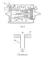
- a gas turbine engine 10 is shown in Figure 1 and comprises an air intake 12 and a propulsive fan 14 that generates two airflows A and B.
- the gas turbine engine 10 comprises, in axial flow A, an intermediate pressure compressor 16, a high pressure compressor 18, a combustor 20, a high pressure turbine 22, an intermediate pressure turbine 24, a low pressure turbine 26 and an exhaust nozzle 28.
- a nacelle 30 surrounds the gas turbine engine 10 and defines, in axial flow B, a bypass duct 32.
- the radially inner extent of the bypass duct 32 is defined by an annular inner wall 34.
- the annular inner wall 34 defines at least two exemplary fire zones, zone z2 and zone z3, that are axially separated by a barrier wall 36.
- Ventillets 38 Downstream of the barrier wall 36 there is an array of ventilation inlets 38 that are equi-angularly spaced around at least a portion of the circumference of the annular inner wall 34 to permit air to flow from the bypass duct 32 into fire zone z3 to ventilate and purge it.
- Each ventilation inlet 38 has the form of a static pressure tapping, being a pipe directed radially so that it extends substantially perpendicularly to the flow through the bypass duct 32, as shown in Figure 2 .
- One problem with this arrangement of ventilation inlet 38 is that in order to meet certification requirements for minimum purge flow at all bypass flow rates, the ventilation inlet 38 has a comparatively large diameter.
- an excessive amount of air is diverted from the bypass duct 32 into the ventilation inlet 38, thereby reducing the amount of air available to provide thrust through the exhaust nozzle of the bypass duct 32. This has a disadvantageous effect on specific fuel consumption and the propulsive efficiency of the engine 10.
- valves It is known to provide a valve to regulate the amount of bypass flow diverted into the ventilation inlet 38.
- such valves are heavy (which is particularly critical for aerospace applications of a gas turbine engine), expensive and may be unreliable. Furthermore, they require active management via control processing which offers a further failure mode.
- the present invention provides a ventilation inlet that seeks to address the aforementioned problems.
- the present invention provides a ventilation inlet comprising a ventilation pipe to receive flow from a first flow zone and to deliver the flow to a second flow zone; a divider arranged to divide a portion of the ventilation pipe into a static pressure zone and a total pressure zone; and a deflector arranged to direct flow from the total pressure zone at least partially across the static pressure zone to restrict delivery of the flow from the static pressure zone to the second flow zone dependent on the pressure of the flow in the first flow zone.
- the ventilation inlet allows the flow delivered to the second flow zone to be passively restricted dependent on the pressure and flow rate in the first flow zone.
- a prior art ventilation inlet can be modified with ease to become a ventilation inlet according to the present invention so that it is possible to retrofit or modify ventilation inlets to obtain the benefits of the present invention.
- the flow may be ventilation flow.
- the ventilation pipe may be circular in cross-section.
- the divider may be semi-circular in cross-section.
- the divider may have a complementary shape to the ventilation pipe wall in the total pressure zone or may be a different shape.
- the divider may be straight in cross-section.
- the divider may be angled at its end close to the first flow zone.
- this directs flow into the ventilation pipe and makes the aperture of the total pressure zone more like a total pressure inlet.
- the divider may be angled from its end close to the first flow zone to its other end. This configuration accelerates the flow through the total pressure zone.
- the divider may extend towards but not meet the end of the ventilation pipe close to the first flow zone. Beneficially this enables the total pressure zone to recover total pressure.
- the deflector may protrude into the ventilation pipe from a wall close to the total pressure zone and be spaced from the end of the divider.
- the deflector may protrude further into the static pressure zone than the divider.
- the ventilation inlet may further comprise a fire zone ventilation inlet.
- the present invention also provides a gas turbine engine comprising a ventilation inlet as described wherein the first flow one comprises a bypass flow duct.
- fire zones are specific examples of nacelle cavities that require purging and / or ventilation and that the specific description is not intended to be limiting of the claimed invention.
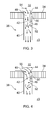
- FIG. 3 and 4 An exemplary embodiment of the present invention is shown in Figures 3 and 4 .
- a portion of the annular inner wall 34 is shown that bounds the bypass duct 32.
- a ventilation pipe 40 extends through the inner wall 34 from the bypass duct 32 into fire zone z3 to form the ventilation inlet 38.
- the ventilation pipe 40 is a hollow tube, for example having circular cross-section, through which bypass air is diverted to provide purging and ventilation air to zone z3.
- the dimensions of the ventilation inlet 38 may be substantially the same as for prior art ventilation inlets 38.
- the diameter is large enough that there is a region of higher pressure flow that forms against the downstream, trailing edge of the ventilation pipe 40 and a region of lower pressure flow that forms against the upstream, leading edge. Downstream and upstream are used relative to the flow through the bypass duct 32, left to right as illustrated in the figures.
- the ventilation inlet 38 is shaped as a static pressure inlet, the downstream portion tends to recover total pressure flow instead.
- the ventilation inlet 38 also comprises a divider 42, having a first end 44 and a second end 46.
- the divider 42 extends inside the ventilation pipe 40, approximately parallel to the longitudinal axis of the ventilation pipe 40. Its first end 44 is located close to the junction between the ventilation pipe 40 and the inner wall 34 but preferably does not meet the end of the ventilation pipe 40. Thus, as illustrated, the first end 44 is below the level of the top of the ventilation pipe 40.
- the second end 46 is within the ventilation pipe 40, towards fire zone z3.
- the divider 42 is substantially shorter than the ventilation pipe 40 so that its second end 46 is well inside the ventilation pipe 40.
- the divider 42 is semi-circular in cross-section and is of complementary shape to the downstream part of the wall of the ventilation pipe 40 so that its locus is upstream.
- the divider 42 also has a pair of wings that connect the semi-circular portion with the wall of the ventilation pipe 40 to divide that portion of the ventilation pipe 40 into two zones.
- the upstream zone is a static pressure zone 48 whilst the zone downstream of the divider 42 is a total pressure zone 50.
- the precise dimensions and the location of the divider 42 relative to the ventilation pipe 40 is a matter of optimisation for a specific application of the present invention.
- the deflector 52 is arranged to extend from the downstream wall of the ventilation pipe 40 towards its longitudinal axis. It preferably has a complementary shape to the total pressure zone 50 as defined by the divider 42, thus part-annular as shown in Figure 5 .
- the deflector 52 extends at least as far into the ventilation pipe 40 as the position of the divider 42 and, in some applications, may extend further into the static pressure zone 48.
- the deflector 52 is arranged to direct flow from the total pressure zone 50 at least partially across the static pressure zone 48 to restrict delivery of the flow from the static pressure zone 48 to the second flow zone, fire zone z3.
- Figure 3 shows a first flow state in which the bypass flow is at a low pressure ratio as indicated by small arrow 54.
- Flow arrows in the ventilation pipe 40 show the flow paths for this first flow state.
- some of the bypass flow 54 is diverted into the ventilation inlet 38 and a majority of that flow passes through the static pressure zone 48 upstream of the divider 42.
- a minority of the diverted flow passes through the total pressure zone 50 downstream of the divider 42 until it reaches the deflector 52.
- the deflector 52 alters the direction of the flow towards the static pressure zone 48.
- the deflected flow forms only a weak air curtain which does not significantly restrict the flow from the static pressure zone 48 towards the end of the ventilation pipe 40 into the fire zone z3. Hence substantially all of the flow passes through the ventilation inlet 38 to ventilate and purge fire zone z3.
- Figure 4 shows a second flow state in which the bypass flow is at a high pressure ratio as indicated by large arrow 56.
- a majority of the flow diverted from the bypass duct 32 passes into the static pressure zone 48 and a minority of that flow passes into the total pressure zone 50.
- the flow through the total pressure zone 50 flows more quickly, because it is at a higher pressure than in the first flow state, so when it reaches the deflector 52 it is deflected to flow substantially in the direction of the deflector 52.
- it flows across the static pressure zone 48 to form an air curtain that significantly restricts the air passing through the static pressure zone 48 from flowing further through the ventilation pipe 40 towards the fire zone z3.
- the deflected flow is deflected back into the previous flow direction either by reaching the upstream wall of the ventilation pipe 40 or by interaction with the flow through the static pressure zone 48, depending on the relative pressures in the flow.
- the ventilation inlet 38 is restricted and a lower proportion of bypass air is able to flow into fire zone z3 to ventilate and purge it.
- first and second flow states illustrate substantially the extremes of flow behaviour through the ventilation inlet 38.
- the ventilation inlet 38 ensures that at no flow state is an excess purge flow diverted from the bypass duct 32. This improves the efficiency and therefore the specific fuel consumption of the engine compared to prior art arrangements.
- the ventilation inlet 38 is a passive system to regulate the amount of air that passes through it, based on the flow pressure entering the ventilation inlet 38. Beneficially therefore, there are no moving parts unlike in active arrangements so that there is no failure mode that can result in no purge or ventilation air being provided to fire zone z3. Additionally, the divider 42 and deflector 52 add little weight to the ventilation inlet 38, which is advantageous for aero gas turbine engine applications, and do not add significantly to the cost of the ventilation inlets 38. Furthermore, since the divider 42 and deflector 52 are fixed into a ventilation pipe 40 having substantially the same dimensions as the prior art ventilation inlet 38, the divider 42 and deflector 52 may be retrofitted to extant ventilation inlets 38 to obtain the benefits of the present invention with minimal expenditure or modification.
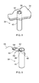
- FIG. 7 shows an alternative embodiment of the ventilation inlet 38 according to the present invention.
- the divider 42 does not have complementary shape to the downstream portion of the wall of the ventilation pipe 40. Instead the divider 42 is semi-circular in cross-section with its locus downstream. In this embodiment the divider 42 meets the wall of the ventilation pipe 40 without needing wings.
- the deflector 52 in this embodiment has a complementary shape to the cross-section of the total pressure zone 50, therefore being substantially oval or egg-shaped.
- the divider 42 has been described as extending parallel to the longitudinal axis of the ventilation pipe 40, it may be not wholly parallel.
- the first end 44 of the divider 42 may be angled towards the upstream direction to encourage flow to pass into the total pressure zone 50 and to better resemble a total pressure inlet.
- the entire divider 42 may be angled from its first end 44 to its second end 46 so that its first end 44 is further upstream than its second end 46. This has the effect of accelerating the flow through the total pressure zone 50 so that it forms an air curtain to restrict the flow at a lower bypass pressure ratio.
- the deflector 52 may also take other forms. It may complement the cross-sectional shape of the total pressure zone 50 as in the embodiments described above. Alternatively the deflector 52 may have a different shape to the total pressure zone 50, for example be semi-circular when the total pressure zone 50 is semi-annular in cross-section.
- the deflector 52 may alternatively be angled relative to the radius of the ventilation pipe 40, towards or away from the fire zone z3. In particular, it may be beneficial to angle the deflector 52 so that its free end is further from the fire zone z3 than the end coupled to the downstream wall of the ventilation pipe 40.
- FIG 8 shows a further alternative embodiment of the ventilation inlet 38 of the present invention.
- the ventilation pipe 40 remains as in the previous embodiments and includes a divider 42 and a deflector 52 having any of the forms discussed herein.
- the first end 44 of the divider 42 may be level with the top of the ventilation pipe 40, at its junction with the inner wall 34.
- a hood 58 is provided in order to divert some of the bypass flow into the ventilation inlet 38.
- the hood 58 extends from the downstream periphery of the ventilation pipe 40 into the bypass duct 32 from the inner wall 34.
- the hood 58 is partially spherical, for example quarter-spherical.
- the hood 58 captures and diverts some of the bypass flow into the ventilation inlet 38 although there may be a small degradation of the engine 10 performance caused by drag on the bypass flow as it passes the hood 58.
- the ventilation pipe 40 has been described as cylindrical it may have any other shape suitable for a pressure tapping.
- it may be teardrop-shaped in cross-section, with the bulbous end upstream or downstream of the pointed end depending on the particular application.
- the ventilation pipe 40 may have any other cross-sectional shape such as square, rectangular or another polygon.
- the shapes of the divider 42 and the deflector 52 may be similarly adjusted.
- FIG. 9 shows an alternative method of modifying an extant ventilation inlet 38 in accordance with the present invention.
- the ventilation pipe 40 is a simple cylindrical tube that receives flow at static pressure as indicated by arrow 60.
- a further pipe 62 is provided that has a first end 64 configured as a total pressure inlet to receive total pressure flow 68 at a location proximal to the ventilation pipe 40 inlet.
- the further pipe 62 has a second end 66 that is coupled to the ventilation pipe 40 via an aperture in its downstream wall.
- the further pipe 62 forms the total pressure zone 50 whilst the ventilation pipe 40 forms the static pressure zone 48.
- the rate of flow through the further pipe 62 is dependent on the rate of bypass flow. In turn this governs the force of the air curtain jetted from the second end 66 of the further pipe 62 and the amount of restriction of the ventilation inlet 38 provided.
- This arrangement therefore acts in the same manner as the other embodiments of the invention.
- the ventilation inlet 38 of the present invention is a simple configuration comprising minimal parts. Thus it generates fewer losses of acoustic area than alternative, more complex solutions to the problem of diverting ventilation fluid to a cavity from a flow having different pressures and flow rates at different conditions.
- the ventilation inlet 38 of the present invention has been described with respect to providing ventilation and purge flow to fire zone z3 from the bypass duct 32 of a gas turbine engine 10, other applications are within the scope of the claimed invention.
- the ventilation inlet 38 can be used to cool other portions of a gas turbine engine 10, such as an engine electronic controller, or to provide heat to areas such as to de-ice the nacelle 30 near the air intake 12, particularly on engine starting.
- the ventilation inlet 38 can be used with equal felicity to ventilate or purge aircraft cavities such as an electronics bay, or to cool cavities in power plants including nuclear power plants.
Landscapes
- Engineering & Computer Science (AREA)
- Chemical & Material Sciences (AREA)
- Combustion & Propulsion (AREA)
- Mechanical Engineering (AREA)
- General Engineering & Computer Science (AREA)
- Physics & Mathematics (AREA)
- Fluid Mechanics (AREA)
- Jet Pumps And Other Pumps (AREA)
- Fire-Extinguishing By Fire Departments, And Fire-Extinguishing Equipment And Control Thereof (AREA)
- Ventilation (AREA)
- Turbine Rotor Nozzle Sealing (AREA)
Applications Claiming Priority (1)
| Application Number | Priority Date | Filing Date | Title |
|---|---|---|---|
| GBGB1013093.8A GB201013093D0 (en) | 2010-08-04 | 2010-08-04 | Ventilation inlet |
Publications (3)
| Publication Number | Publication Date |
|---|---|
| EP2415992A2 true EP2415992A2 (de) | 2012-02-08 |
| EP2415992A3 EP2415992A3 (de) | 2014-01-22 |
| EP2415992B1 EP2415992B1 (de) | 2018-09-12 |
Family
ID=42799576
Family Applications (1)
| Application Number | Title | Priority Date | Filing Date |
|---|---|---|---|
| EP11172843.2A Not-in-force EP2415992B1 (de) | 2010-08-04 | 2011-07-06 | Lüftungseinlass für einen gasturbinenmotor |
Country Status (3)
| Country | Link |
|---|---|
| US (1) | US8858163B2 (de) |
| EP (1) | EP2415992B1 (de) |
| GB (1) | GB201013093D0 (de) |
Cited By (5)
| Publication number | Priority date | Publication date | Assignee | Title |
|---|---|---|---|---|
| EP2860412A1 (de) * | 2013-10-10 | 2015-04-15 | Rolls-Royce plc | Gasturbinenmotor |
| EP2898190A4 (de) * | 2012-09-21 | 2015-10-14 | United Technologies Corp | Entlüftungsanschlussrippen für turbomaschinengehäuse |
| EP2966288A1 (de) * | 2014-07-11 | 2016-01-13 | Rolls-Royce plc | Lüftungseinlass |
| US9726030B2 (en) | 2013-08-30 | 2017-08-08 | Rolls-Royce Plc | Flow deflector arrangement |
| EP4102041A1 (de) * | 2021-06-10 | 2022-12-14 | Pratt & Whitney Canada Corp. | Turbogebläsemotor und betriebsverfahren dafür |
Families Citing this family (7)
| Publication number | Priority date | Publication date | Assignee | Title |
|---|---|---|---|---|
| GB0822639D0 (en) * | 2008-12-12 | 2009-01-21 | Rolls Royce Plc | By virtue of section 39(1)(a) of the Patents Act 1977 |
| FR2982588B1 (fr) * | 2011-11-10 | 2013-11-22 | Aircelle Sa | Panneau composite a ecope de prelevement integree |
| US9194330B2 (en) * | 2012-07-31 | 2015-11-24 | United Technologies Corporation | Retrofitable auxiliary inlet scoop |
| US10215442B2 (en) * | 2014-07-30 | 2019-02-26 | The Boeing Company | Ventilation system and method including a diverter duct for fluidly decoupling fans |
| US20180008547A1 (en) * | 2015-02-02 | 2018-01-11 | Aurobindo Pharma Ltd | Stable Compositions comprising Linaclotide |
| CN115419507B (zh) * | 2022-09-23 | 2025-02-28 | 中国商用飞机有限责任公司 | 用于涡扇发动机核心舱的通风进气系统 |
| US12180911B2 (en) * | 2023-04-21 | 2024-12-31 | Rtx Corporation | Ducted firewall with upper bifi bleed for modulated core ventilation |
Family Cites Families (10)
| Publication number | Priority date | Publication date | Assignee | Title |
|---|---|---|---|---|
| US5655359A (en) | 1995-05-15 | 1997-08-12 | The Boeing Company | Passive cooling device and method for cooling an auxiliary power unit on an airplane |
| US6050527A (en) * | 1997-12-19 | 2000-04-18 | The Boeing Company | Flow control device to eliminate cavity resonance |
| GB0009890D0 (en) * | 2000-04-20 | 2000-06-07 | Thames Water Utilities | Flow deflecting device |
| US7344107B2 (en) * | 2004-10-26 | 2008-03-18 | The Boeing Company | Dual flow APU inlet and associated systems and methods |
| GB2443830B (en) | 2006-11-15 | 2010-01-20 | Rolls Royce Plc | Cowling arrangement |
| US7556223B2 (en) | 2006-12-04 | 2009-07-07 | The Boeing Company | Vent system for an aerospace vehicle |
| DE102008009274B4 (de) | 2008-02-15 | 2011-06-01 | Airbus Operations Gmbh | System und Verfahren zur Belüftung eines Bereichs, insbesondere eines explosionsgefährdeten Bereichs eines Luftfahrzeugs |
| FR2936778B1 (fr) | 2008-10-07 | 2011-06-10 | Airbus France | Agencement d'entree d'air pour aeronef |
| US8024935B2 (en) * | 2008-11-21 | 2011-09-27 | Honeywell International Inc. | Flush inlet scoop design for aircraft bleed air system |
| US8113313B2 (en) * | 2009-01-28 | 2012-02-14 | Areva Np Inc. | Pipe assembly with scoop for directing fluid into a standpipe and for mitigating acoustic and vortex coupled resonance |
-
2010
- 2010-08-04 GB GBGB1013093.8A patent/GB201013093D0/en not_active Ceased
-
2011
- 2011-07-06 US US13/177,078 patent/US8858163B2/en not_active Expired - Fee Related
- 2011-07-06 EP EP11172843.2A patent/EP2415992B1/de not_active Not-in-force
Non-Patent Citations (1)
| Title |
|---|
| None |
Cited By (8)
| Publication number | Priority date | Publication date | Assignee | Title |
|---|---|---|---|---|
| EP2898190A4 (de) * | 2012-09-21 | 2015-10-14 | United Technologies Corp | Entlüftungsanschlussrippen für turbomaschinengehäuse |
| US9726030B2 (en) | 2013-08-30 | 2017-08-08 | Rolls-Royce Plc | Flow deflector arrangement |
| EP2860412A1 (de) * | 2013-10-10 | 2015-04-15 | Rolls-Royce plc | Gasturbinenmotor |
| US10024242B2 (en) | 2013-10-10 | 2018-07-17 | Rolls-Royce Plc | Gas turbine engine with a fire wall and an off-take device |
| EP2966288A1 (de) * | 2014-07-11 | 2016-01-13 | Rolls-Royce plc | Lüftungseinlass |
| US10006372B2 (en) | 2014-07-11 | 2018-06-26 | Rolls-Royce Plc | Ventilation inlet |
| EP4102041A1 (de) * | 2021-06-10 | 2022-12-14 | Pratt & Whitney Canada Corp. | Turbogebläsemotor und betriebsverfahren dafür |
| US11603796B2 (en) | 2021-06-10 | 2023-03-14 | Pratt & Whitney Canada Corp. | Turbofan engine and method of operating same |
Also Published As
| Publication number | Publication date |
|---|---|
| US8858163B2 (en) | 2014-10-14 |
| GB201013093D0 (en) | 2010-09-15 |
| EP2415992B1 (de) | 2018-09-12 |
| EP2415992A3 (de) | 2014-01-22 |
| US20120034068A1 (en) | 2012-02-09 |
Similar Documents
| Publication | Publication Date | Title |
|---|---|---|
| US8858163B2 (en) | Ventilation inlet | |
| US8192147B2 (en) | Nacelle assembly having inlet bleed | |
| US9004399B2 (en) | Nacelle flow assembly | |
| US7837436B2 (en) | Method and apparatus for regulating fluid flow through a turbine engine | |
| US8408008B2 (en) | Scoop of a running-gap control system of an aircraft gas turbine | |
| EP3108129B1 (de) | Zwischengehäusestruktur für einen gasturbinenmotorverdichter mit einem integrierten verteiler für klimaregelungssystem und verfahren zur bereitstellung sauberer zapfluft für das klimaregelungssystem | |
| JP5121339B2 (ja) | スロート部を擬似的に変化させるバイパスターボ機械 | |
| EP1998027B1 (de) | Gasturbine mit einem Plenum innerhalb einer Triebwerksgondel und einem Zapfluftsystem | |
| US8578700B2 (en) | Gas turbine engine with fluid mixing arrangement | |
| CN115723945B (zh) | 具有后发动机的飞行器和用于该飞行器的空气注入组件 | |
| CN105408611A (zh) | 用于喷气发动机的次级喷嘴 | |
| CN105190005A (zh) | 用于喷气发动机的多喷嘴分流器 | |
| US10082040B2 (en) | Aircraft comprising a turbine engine incorporated into the rear fuselage with variable supply | |
| EP3483395B1 (de) | Kanäle zwischen turbinen mit strömungsregelungsmechanismen | |
| EP2715094B1 (de) | Ein strukturgitter eines lufteinlasses eines flugzeuges bestehend aus einer anordnung von durchgängen mit hexagonalen querschnitt | |
| US9879636B2 (en) | System of support thrust from wasted exhaust | |
| US9759133B2 (en) | Turbofan with variable bypass flow | |
| CN111495227B (zh) | 流动调节系统 | |
| CN115516195A (zh) | 带有通道的声学优化排放管线网格 | |
| US9435292B2 (en) | Turbine engine with thrust vectoring exhaust nozzle | |
| EP3112646A1 (de) | System zur schuboptimierung |
Legal Events
| Date | Code | Title | Description |
|---|---|---|---|
| AK | Designated contracting states |
Kind code of ref document: A2 Designated state(s): AL AT BE BG CH CY CZ DE DK EE ES FI FR GB GR HR HU IE IS IT LI LT LU LV MC MK MT NL NO PL PT RO RS SE SI SK SM TR |
|
| AX | Request for extension of the european patent |
Extension state: BA ME |
|
| PUAI | Public reference made under article 153(3) epc to a published international application that has entered the european phase |
Free format text: ORIGINAL CODE: 0009012 |
|
| PUAL | Search report despatched |
Free format text: ORIGINAL CODE: 0009013 |
|
| AK | Designated contracting states |
Kind code of ref document: A3 Designated state(s): AL AT BE BG CH CY CZ DE DK EE ES FI FR GB GR HR HU IE IS IT LI LT LU LV MC MK MT NL NO PL PT RO RS SE SI SK SM TR |
|
| AX | Request for extension of the european patent |
Extension state: BA ME |
|
| RIC1 | Information provided on ipc code assigned before grant |
Ipc: F02K 3/075 20060101ALI20131216BHEP Ipc: F02C 7/25 20060101ALI20131216BHEP Ipc: F02C 9/18 20060101AFI20131216BHEP |
|
| 17P | Request for examination filed |
Effective date: 20140722 |
|
| RBV | Designated contracting states (corrected) |
Designated state(s): AL AT BE BG CH CY CZ DE DK EE ES FI FR GB GR HR HU IE IS IT LI LT LU LV MC MK MT NL NO PL PT RO RS SE SI SK SM TR |
|
| RAP1 | Party data changed (applicant data changed or rights of an application transferred) |
Owner name: ROLLS-ROYCE PLC |
|
| 17Q | First examination report despatched |
Effective date: 20150708 |
|
| GRAP | Despatch of communication of intention to grant a patent |
Free format text: ORIGINAL CODE: EPIDOSNIGR1 |
|
| STAA | Information on the status of an ep patent application or granted ep patent |
Free format text: STATUS: GRANT OF PATENT IS INTENDED |
|
| INTG | Intention to grant announced |
Effective date: 20180419 |
|
| GRAS | Grant fee paid |
Free format text: ORIGINAL CODE: EPIDOSNIGR3 |
|
| GRAA | (expected) grant |
Free format text: ORIGINAL CODE: 0009210 |
|
| STAA | Information on the status of an ep patent application or granted ep patent |
Free format text: STATUS: THE PATENT HAS BEEN GRANTED |
|
| AK | Designated contracting states |
Kind code of ref document: B1 Designated state(s): AL AT BE BG CH CY CZ DE DK EE ES FI FR GB GR HR HU IE IS IT LI LT LU LV MC MK MT NL NO PL PT RO RS SE SI SK SM TR |
|
| REG | Reference to a national code |
Ref country code: GB Ref legal event code: FG4D |
|
| REG | Reference to a national code |
Ref country code: CH Ref legal event code: EP |
|
| REG | Reference to a national code |
Ref country code: IE Ref legal event code: FG4D |
|
| REG | Reference to a national code |
Ref country code: DE Ref legal event code: R096 Ref document number: 602011051933 Country of ref document: DE |
|
| REG | Reference to a national code |
Ref country code: AT Ref legal event code: REF Ref document number: 1040870 Country of ref document: AT Kind code of ref document: T Effective date: 20181015 |
|
| REG | Reference to a national code |
Ref country code: NL Ref legal event code: MP Effective date: 20180912 |
|
| REG | Reference to a national code |
Ref country code: LT Ref legal event code: MG4D |
|
| PG25 | Lapsed in a contracting state [announced via postgrant information from national office to epo] |
Ref country code: FI Free format text: LAPSE BECAUSE OF FAILURE TO SUBMIT A TRANSLATION OF THE DESCRIPTION OR TO PAY THE FEE WITHIN THE PRESCRIBED TIME-LIMIT Effective date: 20180912 Ref country code: LT Free format text: LAPSE BECAUSE OF FAILURE TO SUBMIT A TRANSLATION OF THE DESCRIPTION OR TO PAY THE FEE WITHIN THE PRESCRIBED TIME-LIMIT Effective date: 20180912 Ref country code: RS Free format text: LAPSE BECAUSE OF FAILURE TO SUBMIT A TRANSLATION OF THE DESCRIPTION OR TO PAY THE FEE WITHIN THE PRESCRIBED TIME-LIMIT Effective date: 20180912 Ref country code: SE Free format text: LAPSE BECAUSE OF FAILURE TO SUBMIT A TRANSLATION OF THE DESCRIPTION OR TO PAY THE FEE WITHIN THE PRESCRIBED TIME-LIMIT Effective date: 20180912 Ref country code: NO Free format text: LAPSE BECAUSE OF FAILURE TO SUBMIT A TRANSLATION OF THE DESCRIPTION OR TO PAY THE FEE WITHIN THE PRESCRIBED TIME-LIMIT Effective date: 20181212 Ref country code: GR Free format text: LAPSE BECAUSE OF FAILURE TO SUBMIT A TRANSLATION OF THE DESCRIPTION OR TO PAY THE FEE WITHIN THE PRESCRIBED TIME-LIMIT Effective date: 20181213 Ref country code: BG Free format text: LAPSE BECAUSE OF FAILURE TO SUBMIT A TRANSLATION OF THE DESCRIPTION OR TO PAY THE FEE WITHIN THE PRESCRIBED TIME-LIMIT Effective date: 20181212 |
|
| PG25 | Lapsed in a contracting state [announced via postgrant information from national office to epo] |
Ref country code: LV Free format text: LAPSE BECAUSE OF FAILURE TO SUBMIT A TRANSLATION OF THE DESCRIPTION OR TO PAY THE FEE WITHIN THE PRESCRIBED TIME-LIMIT Effective date: 20180912 Ref country code: ES Free format text: LAPSE BECAUSE OF FAILURE TO SUBMIT A TRANSLATION OF THE DESCRIPTION OR TO PAY THE FEE WITHIN THE PRESCRIBED TIME-LIMIT Effective date: 20180912 Ref country code: HR Free format text: LAPSE BECAUSE OF FAILURE TO SUBMIT A TRANSLATION OF THE DESCRIPTION OR TO PAY THE FEE WITHIN THE PRESCRIBED TIME-LIMIT Effective date: 20180912 Ref country code: AL Free format text: LAPSE BECAUSE OF FAILURE TO SUBMIT A TRANSLATION OF THE DESCRIPTION OR TO PAY THE FEE WITHIN THE PRESCRIBED TIME-LIMIT Effective date: 20180912 |
|
| REG | Reference to a national code |
Ref country code: AT Ref legal event code: MK05 Ref document number: 1040870 Country of ref document: AT Kind code of ref document: T Effective date: 20180912 |
|
| PG25 | Lapsed in a contracting state [announced via postgrant information from national office to epo] |
Ref country code: IT Free format text: LAPSE BECAUSE OF FAILURE TO SUBMIT A TRANSLATION OF THE DESCRIPTION OR TO PAY THE FEE WITHIN THE PRESCRIBED TIME-LIMIT Effective date: 20180912 Ref country code: NL Free format text: LAPSE BECAUSE OF FAILURE TO SUBMIT A TRANSLATION OF THE DESCRIPTION OR TO PAY THE FEE WITHIN THE PRESCRIBED TIME-LIMIT Effective date: 20180912 Ref country code: CZ Free format text: LAPSE BECAUSE OF FAILURE TO SUBMIT A TRANSLATION OF THE DESCRIPTION OR TO PAY THE FEE WITHIN THE PRESCRIBED TIME-LIMIT Effective date: 20180912 Ref country code: RO Free format text: LAPSE BECAUSE OF FAILURE TO SUBMIT A TRANSLATION OF THE DESCRIPTION OR TO PAY THE FEE WITHIN THE PRESCRIBED TIME-LIMIT Effective date: 20180912 Ref country code: PL Free format text: LAPSE BECAUSE OF FAILURE TO SUBMIT A TRANSLATION OF THE DESCRIPTION OR TO PAY THE FEE WITHIN THE PRESCRIBED TIME-LIMIT Effective date: 20180912 Ref country code: EE Free format text: LAPSE BECAUSE OF FAILURE TO SUBMIT A TRANSLATION OF THE DESCRIPTION OR TO PAY THE FEE WITHIN THE PRESCRIBED TIME-LIMIT Effective date: 20180912 Ref country code: AT Free format text: LAPSE BECAUSE OF FAILURE TO SUBMIT A TRANSLATION OF THE DESCRIPTION OR TO PAY THE FEE WITHIN THE PRESCRIBED TIME-LIMIT Effective date: 20180912 Ref country code: IS Free format text: LAPSE BECAUSE OF FAILURE TO SUBMIT A TRANSLATION OF THE DESCRIPTION OR TO PAY THE FEE WITHIN THE PRESCRIBED TIME-LIMIT Effective date: 20190112 |
|
| PG25 | Lapsed in a contracting state [announced via postgrant information from national office to epo] |
Ref country code: SK Free format text: LAPSE BECAUSE OF FAILURE TO SUBMIT A TRANSLATION OF THE DESCRIPTION OR TO PAY THE FEE WITHIN THE PRESCRIBED TIME-LIMIT Effective date: 20180912 Ref country code: PT Free format text: LAPSE BECAUSE OF FAILURE TO SUBMIT A TRANSLATION OF THE DESCRIPTION OR TO PAY THE FEE WITHIN THE PRESCRIBED TIME-LIMIT Effective date: 20190112 Ref country code: SM Free format text: LAPSE BECAUSE OF FAILURE TO SUBMIT A TRANSLATION OF THE DESCRIPTION OR TO PAY THE FEE WITHIN THE PRESCRIBED TIME-LIMIT Effective date: 20180912 |
|
| REG | Reference to a national code |
Ref country code: DE Ref legal event code: R097 Ref document number: 602011051933 Country of ref document: DE |
|
| PLBE | No opposition filed within time limit |
Free format text: ORIGINAL CODE: 0009261 |
|
| STAA | Information on the status of an ep patent application or granted ep patent |
Free format text: STATUS: NO OPPOSITION FILED WITHIN TIME LIMIT |
|
| PG25 | Lapsed in a contracting state [announced via postgrant information from national office to epo] |
Ref country code: DK Free format text: LAPSE BECAUSE OF FAILURE TO SUBMIT A TRANSLATION OF THE DESCRIPTION OR TO PAY THE FEE WITHIN THE PRESCRIBED TIME-LIMIT Effective date: 20180912 |
|
| 26N | No opposition filed |
Effective date: 20190613 |
|
| PG25 | Lapsed in a contracting state [announced via postgrant information from national office to epo] |
Ref country code: SI Free format text: LAPSE BECAUSE OF FAILURE TO SUBMIT A TRANSLATION OF THE DESCRIPTION OR TO PAY THE FEE WITHIN THE PRESCRIBED TIME-LIMIT Effective date: 20180912 |
|
| PGFP | Annual fee paid to national office [announced via postgrant information from national office to epo] |
Ref country code: GB Payment date: 20190729 Year of fee payment: 9 |
|
| REG | Reference to a national code |
Ref country code: DE Ref legal event code: R119 Ref document number: 602011051933 Country of ref document: DE |
|
| PG25 | Lapsed in a contracting state [announced via postgrant information from national office to epo] |
Ref country code: MC Free format text: LAPSE BECAUSE OF FAILURE TO SUBMIT A TRANSLATION OF THE DESCRIPTION OR TO PAY THE FEE WITHIN THE PRESCRIBED TIME-LIMIT Effective date: 20180912 |
|
| REG | Reference to a national code |
Ref country code: CH Ref legal event code: PL |
|
| PG25 | Lapsed in a contracting state [announced via postgrant information from national office to epo] |
Ref country code: TR Free format text: LAPSE BECAUSE OF FAILURE TO SUBMIT A TRANSLATION OF THE DESCRIPTION OR TO PAY THE FEE WITHIN THE PRESCRIBED TIME-LIMIT Effective date: 20180912 |
|
| REG | Reference to a national code |
Ref country code: BE Ref legal event code: MM Effective date: 20190731 |
|
| PG25 | Lapsed in a contracting state [announced via postgrant information from national office to epo] |
Ref country code: DE Free format text: LAPSE BECAUSE OF NON-PAYMENT OF DUE FEES Effective date: 20200201 |
|
| PG25 | Lapsed in a contracting state [announced via postgrant information from national office to epo] |
Ref country code: CH Free format text: LAPSE BECAUSE OF NON-PAYMENT OF DUE FEES Effective date: 20190731 Ref country code: LI Free format text: LAPSE BECAUSE OF NON-PAYMENT OF DUE FEES Effective date: 20190731 Ref country code: BE Free format text: LAPSE BECAUSE OF NON-PAYMENT OF DUE FEES Effective date: 20190731 Ref country code: LU Free format text: LAPSE BECAUSE OF NON-PAYMENT OF DUE FEES Effective date: 20190706 |
|
| PG25 | Lapsed in a contracting state [announced via postgrant information from national office to epo] |
Ref country code: FR Free format text: LAPSE BECAUSE OF NON-PAYMENT OF DUE FEES Effective date: 20190731 |
|
| PG25 | Lapsed in a contracting state [announced via postgrant information from national office to epo] |
Ref country code: IE Free format text: LAPSE BECAUSE OF NON-PAYMENT OF DUE FEES Effective date: 20190706 |
|
| GBPC | Gb: european patent ceased through non-payment of renewal fee |
Effective date: 20200706 |
|
| PG25 | Lapsed in a contracting state [announced via postgrant information from national office to epo] |
Ref country code: GB Free format text: LAPSE BECAUSE OF NON-PAYMENT OF DUE FEES Effective date: 20200706 |
|
| PG25 | Lapsed in a contracting state [announced via postgrant information from national office to epo] |
Ref country code: CY Free format text: LAPSE BECAUSE OF FAILURE TO SUBMIT A TRANSLATION OF THE DESCRIPTION OR TO PAY THE FEE WITHIN THE PRESCRIBED TIME-LIMIT Effective date: 20180912 |
|
| PG25 | Lapsed in a contracting state [announced via postgrant information from national office to epo] |
Ref country code: HU Free format text: LAPSE BECAUSE OF FAILURE TO SUBMIT A TRANSLATION OF THE DESCRIPTION OR TO PAY THE FEE WITHIN THE PRESCRIBED TIME-LIMIT; INVALID AB INITIO Effective date: 20110706 Ref country code: MT Free format text: LAPSE BECAUSE OF FAILURE TO SUBMIT A TRANSLATION OF THE DESCRIPTION OR TO PAY THE FEE WITHIN THE PRESCRIBED TIME-LIMIT Effective date: 20180912 |
|
| PG25 | Lapsed in a contracting state [announced via postgrant information from national office to epo] |
Ref country code: MK Free format text: LAPSE BECAUSE OF FAILURE TO SUBMIT A TRANSLATION OF THE DESCRIPTION OR TO PAY THE FEE WITHIN THE PRESCRIBED TIME-LIMIT Effective date: 20180912 |