EP2415950A2 - Fall-through protection for an opening - Google Patents
Fall-through protection for an opening Download PDFInfo
- Publication number
- EP2415950A2 EP2415950A2 EP11176321A EP11176321A EP2415950A2 EP 2415950 A2 EP2415950 A2 EP 2415950A2 EP 11176321 A EP11176321 A EP 11176321A EP 11176321 A EP11176321 A EP 11176321A EP 2415950 A2 EP2415950 A2 EP 2415950A2
- Authority
- EP
- European Patent Office
- Prior art keywords
- fall
- protection
- opening
- support surface
- tubes
- Prior art date
- Legal status (The legal status is an assumption and is not a legal conclusion. Google has not performed a legal analysis and makes no representation as to the accuracy of the status listed.)
- Withdrawn
Links
- 230000002093 peripheral effect Effects 0.000 claims description 15
- 238000000034 method Methods 0.000 claims description 2
- 238000007789 sealing Methods 0.000 description 5
- 238000009413 insulation Methods 0.000 description 4
- 238000010276 construction Methods 0.000 description 3
- 238000004873 anchoring Methods 0.000 description 1
- 230000008878 coupling Effects 0.000 description 1
- 238000010168 coupling process Methods 0.000 description 1
- 238000005859 coupling reaction Methods 0.000 description 1
- 238000009434 installation Methods 0.000 description 1
- 238000012423 maintenance Methods 0.000 description 1
- 238000009418 renovation Methods 0.000 description 1
- 230000000717 retained effect Effects 0.000 description 1
Images



Classifications
-
- E—FIXED CONSTRUCTIONS
- E04—BUILDING
- E04G—SCAFFOLDING; FORMS; SHUTTERING; BUILDING IMPLEMENTS OR AIDS, OR THEIR USE; HANDLING BUILDING MATERIALS ON THE SITE; REPAIRING, BREAKING-UP OR OTHER WORK ON EXISTING BUILDINGS
- E04G21/00—Preparing, conveying, or working-up building materials or building elements in situ; Other devices or measures for constructional work
- E04G21/32—Safety or protective measures for persons during the construction of buildings
- E04G21/3204—Safety or protective measures for persons during the construction of buildings against falling down
-
- E—FIXED CONSTRUCTIONS
- E04—BUILDING
- E04G—SCAFFOLDING; FORMS; SHUTTERING; BUILDING IMPLEMENTS OR AIDS, OR THEIR USE; HANDLING BUILDING MATERIALS ON THE SITE; REPAIRING, BREAKING-UP OR OTHER WORK ON EXISTING BUILDINGS
- E04G21/00—Preparing, conveying, or working-up building materials or building elements in situ; Other devices or measures for constructional work
- E04G21/32—Safety or protective measures for persons during the construction of buildings
- E04G21/3261—Safety-nets; Safety mattresses; Arrangements on buildings for connecting safety-lines
- E04G21/3266—Safety nets
Definitions
- the present invention relates to a fall-through protection according to the preamble of Claim 1.
- Such a fall-through protection is known from FR 2528898 which describes an opening having a raised edge in which, between the connection of the raised edge and the roof structure, in each corner, strips extend which run from said edge and are fixedly connected to the building structure. Openings are provided in these lips and a fall-through protection can be positioned therein, if necessary. Positioning is achieved by means of downwardly directed curved legs, the lowest part of which is inserted into the protruding parts with openings.
- DE 2701138 discloses a safety net which is supported on the peripheral edge of an opening which is to be secured, in which the support is provided by means of a box profile which is placed on the edge in question.
- DE 3842435 C1 discloses a structure which is composed of tubes and which functions as a fall-through protection, in which the tubes are situated on the respective part of the roof.
- this object is achieved with a fall-through protection having the features of Claim 1.
- a fall-through protection as described above wherein the corner part is provided with a support surface for supporting the former on the upper boundary of an opening and with attachment means which extend from said support surface to the opposite corner for accommodating said tubes and with attachment means for said net.
- the net-supporting frame is not fitted to the edge which bounds the opening, but, according to the present invention, the corner parts are situated inside of the latter on the corners of the edge. As a result thereof, the edge of the opening between the corners is more readily accessible for carrying out maintenance work.
- only the corner parts are provided with a supporting or structural attachment for the net.
- Only the corner parts are subjected to a tensile load which is converted into a compressive load on the tube parts.
- the length of the tubes is adjustable which can be achieved, for example, by using telescopic tube parts.
- a strong lock has to be present between the tube parts.
- This may consist of a pin/hole joint.
- the net is provided with a number of anchorings which can be attached to one of the corners. As a result thereof, the dimensions of the net can be adjusted depending on the size of the opening.
- a retaining part which extends vertically in the position of use is present in order to stabilize the fall-through protection, which extends along the inside of the peripheral edge of the opening in the position of use.
- This retaining part may comprise a tube part.
- the top side of the fall-through protection in the fitted position, is substantially level with or is situated below the top side of the support surface.
- the fall-through protection according to the present invention can also be used in conjunction with further fall-through protection units which are, for example, identical.
- further fall-through protection units which are, for example, identical.
- two adjoining fall-through protection units to share parts of the frame structure.
- the invention also relates to an assembly comprising a building structure having an opening and a fall-through protection arranged inside the opening, wherein said fall-through protection comprises a net and a frame structure supporting the net, which frame structure comprises four tubes which form a rectangle and which each meet in pairs in a corner part, wherein the corner part is provided with a support surface for supporting it on the upper boundary of an opening or with an attachment means which extends from said support surface to the opposite corner for accommodating said tubes and with an attachment means for said net, wherein said fall-through protection with said support surface can be removed from said opening and wherein said support surface comprises a horizontal disc which is flat in the fitted position and which rests on the peripheral edge of said opening.
- the invention also relates to a method for fitting and removing a fall-through protection according to the invention, comprising installing said fall-through protection in an opening of a building structure, wherein said support surface rests on the peripheral edge of a corner in said opening of said building structure, carrying out the desired work and removing said fall-through protection, wherein the removal of said fall-through protection comprises moving said support surface in the plane of said opening towards the centre of said opening in order to release said fall-through protection, followed by the removal of said fall-through protection from said opening.
- a roof or other building structure is denoted by reference numeral 1 and comprises an opening 2 which has a (raised) peripheral edge 3.
- the opening is an opening in a roof, it is often necessary to carry out work thereon in order to make the edge watertight with respect to the environment and, for example, to prepare it for the installation of a skylight or the like. Insulation is applied to the roof which is covered in turn by a sealing layer. On top thereof, the mounting rim for a skylight is placed, which mounting rim is connected to the sealing layer in any suitable way in a sealing manner. If the opening is an opening for the passage of a stair or the like, other measures may be necessary, as a result of which the peripheral edge 3 has to be as accessible as possible.
- the fall-through protection 5 which, for the sake of clarity, is arranged in the non-fitted position at some distance above the hole in Fig. 1 .
- the fall-through protection 5 consists of a net (not shown in Fig. 1 , see in particular Figs. 4 and 5 ) and a frame structure 7 supporting the net.
- the frame structure 7 is composed of opposite tubes 8 and 9, respectively, which always meet in a corner part 10.
- corner part 10 is provided with a substantially horizontal support plate 11 and an opening for fitting an attachment means for the net provided with a substantially horizontal disc-shaped support plate 11.
- a vertical tube 12 is present at the corner part.
- the purpose of the sockets 13 is to receive the tubes 8 and 9.
- Fig. 2 shows that an insulating layer 30 is applied to the roof in a conventional manner (preferably after the fall-through protection has been fitted). On top thereof, a mounting rim 33 of, for example, a skylight may be placed, which may be followed by the application of a sealing layer 31 made of bituminous or plastic material on top of which the skylight can subsequently be fitted. All of this work can be carried out while the fall-through protection is present.
- the fall-through protection can be removed without damaging the structure which has been built (in the meantime). This is effected by moving the support surface 11 in the horizontal direction, in the direction of the centre of the opening. In the example shown in Fig. 2 , the insulation will in this case spring downwards and form a sealing unit with the rest of the building structure. It can also be seen in Fig. 2 that the top side of the fall-through protection is situated in a low position in the fitted state, that is to say is substantially at the same height as the top side of the support surface 11. As a result thereof, workmen can readily reach parts 31 and 33 and carry out any necessary work thereon without the fall-through protection forming an obstruction, so that the work can be carried out under safe conditions.
- Fig. 4 shows an example of a tube 8 or 9 consisting of the tube parts 16 and 17 which may be mutually telescopic. Openings 19 are provided through which a pin 18 can be pushed so that the position of the tube parts 16 and 17 with respect to one another is fixed.
- Fig. 4 shows that the tube part 17 is provided with a series of aligned openings, while tube part 16 is provided with two through-openings 19. These through-openings may be offset by a quarter turn and the longitudinal distance between them corresponds to approximately half the distance between the openings of the tube part 17.
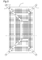
- Fig. 5 shows that a number of strips 21 are provided in the net which can be attached to the frame structure via the opening 4, the attachment means 22 ( Fig. 6 ) and hooks 23. It is possible to fit the hooks 23 at different positions on the strips 21, as a result of which the net can be fitted at sufficient tension, depending on the size of the opening.
- Fig. 6 shows the fitted state of the fall-through protection, partly in detail.
- the substantially horizontal support plates 11 rest on the corners of the edge.
- the tubes 8 and 9 are situated inside the boundary of the peripheral edge 3 and, in this example, are situated below the peripheral edge.
- the top side of the edge is covered by the support plates 11 only at the corners and the remainder of the edge 3 is freely accessible for the purpose of carrying out work and, in addition, the presence of the tubes does not form an obstruction when walking on the roof or another part of the building structure.
- the net 6 is only attached to the corner parts so that these parts are only subjected to tensile load towards the centre of the opening when they are subjected to a load, which tensile load is absorbed by the various tubes 8 and 9.
- the tubes 8, 9 are not subjected to a tensile or flexural load if the net is subjected to a load, so that these tubes 8, 9 can be made relatively lightweight which increases the usability of the fall-through protection.
- removal of the lock 18 makes it possible to push the mutually facing support plates 11 towards one another, as a result of which these are moved underneath the insulating layer 30 ( Fig. 2 ). This takes place at the four corners, following which the fall-through protection can be removed without damaging the subsequently fitted parts.
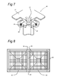
- Fig. 7 shows a variant of the corner part which is denoted overall by reference numeral 40.
- it is configured as a moulded piece and comprises a support plate 41 and sockets 43 for receiving the above-described tubes 8.
- These sockets are configured in such a manner that the tubes 8 can be introduced from the side, that is to say in the direction of the arrow 39, and subsequently fixed by means of pins 45. This makes fitting possible under all circumstances.
- An opening 44 is provided in the U-shaped part for attaching the net thereto, for example, by means of a carbine hook. Due to said U-shaped configuration, such an attachment means can be fitted in a low position, as a result of which it is not touched when plate 41 is walked upon and does not create any risk of tripping or damage.
- Fig. 8 diagrammatically shows an elongate opening 52 in a roof in which two adjoining fall-through protection units 55 are fitted.
- frame structure part 59 is shared by both and use is made of a T-piece 60 to couple the various frame structures and fall-through protection units to one another.
- a T-piece 60 can be provided in the above-described manner with a support surface.
- Such a T-piece can replace a corner piece which may have been present originally and vice versa.
Landscapes
- Engineering & Computer Science (AREA)
- Architecture (AREA)
- Mechanical Engineering (AREA)
- Civil Engineering (AREA)
- Structural Engineering (AREA)
- Emergency Lowering Means (AREA)
- Load-Bearing And Curtain Walls (AREA)
Abstract
Description
- The present invention relates to a fall-through protection according to the preamble of Claim 1.
- Such a fall-through protection is known from
FR 2528898 -
DE 2701138 discloses a safety net which is supported on the peripheral edge of an opening which is to be secured, in which the support is provided by means of a box profile which is placed on the edge in question. -
DE 3842435 C1 discloses a structure which is composed of tubes and which functions as a fall-through protection, in which the tubes are situated on the respective part of the roof. - It is an object of the present invention to provide a fall-through protection which can be transported in a compact manner. In addition, it is an object of the invention to provide a fall-through protection which has a relatively low weight and which makes it possible to carry out work near the boundary of the opening as much as possible.
- It is a further object of the present invention to provide a fall-through protection which can be used for openings of different sizes.
- It is a further object of the present invention to provide a fall-through protection which can be used during construction or repair work on a building structure. This then has to satisfy the requirement that it impedes the work of the individuals in question as little as possible. In addition, it has to be possible to remove said fall-through protection without damaging the building structure.
- According to the present invention, this object is achieved with a fall-through protection having the features of Claim 1.
- According to the present invention, a fall-through protection as described above is provided, wherein the corner part is provided with a support surface for supporting the former on the upper boundary of an opening and with attachment means which extend from said support surface to the opposite corner for accommodating said tubes and with attachment means for said net.
- In contrast with the prior art, the net-supporting frame is not fitted to the edge which bounds the opening, but, according to the present invention, the corner parts are situated inside of the latter on the corners of the edge. As a result thereof, the edge of the opening between the corners is more readily accessible for carrying out maintenance work.
- By using a flat support surface from which no further parts extend, it is possible to remove this support surface in the horizontal direction if the fall-through protection has to be removed. This makes it possible to carry out work along the edge of the opening in the vicinity of the support surface. Thus, it is, for example, possible to let the support surface rest on the peripheral edge of an opening during the construction of a new building or renovation, then apply insulation or another covering on the support surface at the location of said peripheral edge and to remove the fall-through protection once the work has finished by simply moving the support surface to the centre of the opening without further finishing work having to be carried out during which the fall-through protection is not present, as is the case in the prior art. It is also possible, with existing structures, to push the disc-shaped support surface between two parts of the building structure into a peripheral edge and thus to provide support without causing damage to the existing structure.
- According to a specific embodiment of the invention, only the corner parts are provided with a supporting or structural attachment for the net. This means that the tubes between the corner parts are not subjected to load when the net is subjected to load. Only the corner parts are subjected to a tensile load which is converted into a compressive load on the tube parts. Due to the fact that the tube parts are only subjected to a compressive (buckling) load, they can be of a relatively lightweight construction. This makes it possible to produce a very light and compact structure which can be readily transported.
- According to a specific embodiment of the present invention, the length of the tubes is adjustable which can be achieved, for example, by using telescopic tube parts. Obviously, a strong lock has to be present between the tube parts. This may consist of a pin/hole joint. According to an advantageous embodiment of the present invention, the net is provided with a number of anchorings which can be attached to one of the corners. As a result thereof, the dimensions of the net can be adjusted depending on the size of the opening.
- According to a further advantageous embodiment of the present invention, a retaining part which extends vertically in the position of use is present in order to stabilize the fall-through protection, which extends along the inside of the peripheral edge of the opening in the position of use. This retaining part may comprise a tube part.
- According to a further advantageous embodiment of the invention, the top side of the fall-through protection, in the fitted position, is substantially level with or is situated below the top side of the support surface. As a result thereof, it is possible to carry out work on the peripheral edge without the person in question being obstructed by the fall-through protection and yet being fully protected thereby.
- The fall-through protection according to the present invention can also be used in conjunction with further fall-through protection units which are, for example, identical. As a result thereof, it is possible to protect a rectangular opening having, for example, a large longitudinal dimension in a roof or the like by placing a number of fall-through protection units against one another, as described above. In this case, it is possible to couple the fall-through protection units to one another via, for example, a T-piece. In such a case, it is also possible for two adjoining fall-through protection units to share parts of the frame structure.
- The invention also relates to an assembly comprising a building structure having an opening and a fall-through protection arranged inside the opening, wherein said fall-through protection comprises a net and a frame structure supporting the net, which frame structure comprises four tubes which form a rectangle and which each meet in pairs in a corner part, wherein the corner part is provided with a support surface for supporting it on the upper boundary of an opening or with an attachment means which extends from said support surface to the opposite corner for accommodating said tubes and with an attachment means for said net, wherein said fall-through protection with said support surface can be removed from said opening and wherein said support surface comprises a horizontal disc which is flat in the fitted position and which rests on the peripheral edge of said opening.
- The invention also relates to a method for fitting and removing a fall-through protection according to the invention, comprising installing said fall-through protection in an opening of a building structure, wherein said support surface rests on the peripheral edge of a corner in said opening of said building structure, carrying out the desired work and removing said fall-through protection, wherein the removal of said fall-through protection comprises moving said support surface in the plane of said opening towards the centre of said opening in order to release said fall-through protection, followed by the removal of said fall-through protection from said opening.
- The invention will be explained in more detail with reference to an exemplary embodiment illustrated in the drawing, in which:
-
Fig. 1 diagrammatically shows a perspective view of a roof with an opening and a fall-through protection in the non-fitted position; -
Fig. 2 shows a corner part according to the present invention in the fitted position in detail; -
Fig. 3 shows a perspective view of the corner part; -
Fig. 4 shows a tube of adjustable length in detail; -
Fig. 5 shows an example of a net to be used with the invention; -
Fig. 6 shows a part of the fall-through protection in the fitted position in the roof shown inFig. 1 ; -
Fig. 7 shows a variant of the used corner part; and -
Fig. 8 shows an example of the coupling through of fall-through protection units. - In
Fig. 1 , a roof or other building structure is denoted by reference numeral 1 and comprises anopening 2 which has a (raised)peripheral edge 3. If the opening is an opening in a roof, it is often necessary to carry out work thereon in order to make the edge watertight with respect to the environment and, for example, to prepare it for the installation of a skylight or the like. Insulation is applied to the roof which is covered in turn by a sealing layer. On top thereof, the mounting rim for a skylight is placed, which mounting rim is connected to the sealing layer in any suitable way in a sealing manner. If the opening is an opening for the passage of a stair or the like, other measures may be necessary, as a result of which theperipheral edge 3 has to be as accessible as possible. - This is achieved by means of the fall-through
protection 5 which, for the sake of clarity, is arranged in the non-fitted position at some distance above the hole inFig. 1 . This shows that the fall-throughprotection 5 consists of a net (not shown inFig. 1 , see in particularFigs. 4 and5 ) and aframe structure 7 supporting the net. Theframe structure 7 is composed ofopposite tubes 8 and 9, respectively, which always meet in acorner part 10. In addition,corner part 10 is provided with a substantiallyhorizontal support plate 11 and an opening for fitting an attachment means for the net provided with a substantially horizontal disc-shaped support plate 11. In addition, avertical tube 12 is present at the corner part. The purpose of thesockets 13 is to receive thetubes 8 and 9. In this case, reference is made in particular toFig. 2. Fig. 2 shows that aninsulating layer 30 is applied to the roof in a conventional manner (preferably after the fall-through protection has been fitted). On top thereof, amounting rim 33 of, for example, a skylight may be placed, which may be followed by the application of a sealinglayer 31 made of bituminous or plastic material on top of which the skylight can subsequently be fitted. All of this work can be carried out while the fall-through protection is present. - Once the work on the roof has finished, that is to say at the point in time the actual skylight or other closure of the opening can be fitted, the fall-through protection can be removed without damaging the structure which has been built (in the meantime). This is effected by moving the
support surface 11 in the horizontal direction, in the direction of the centre of the opening. In the example shown inFig. 2 , the insulation will in this case spring downwards and form a sealing unit with the rest of the building structure. It can also be seen inFig. 2 that the top side of the fall-through protection is situated in a low position in the fitted state, that is to say is substantially at the same height as the top side of thesupport surface 11. As a result thereof, workmen can readily reachparts - It will be understood that fitting of the fall-through protection can be carried out in reverse order from removal. This means that instead of carrying out a vertical movement as described with reference to
Fig. 1 , in whichpart 11 comes to lie on the peripheral edge of the opening, it is also possible, withopposite corner pieces 10 which are placed facing one another, to place the free end edge of disc-shapedpart 11 in front of the boundary between, for example,insulation 30 and the underlying structure and subsequently to move this in the horizontal direction between them like a kind of knife. As a result thereof, the existing structure is not damaged and there is complete freedom of movement in the space near the fall-through protection to carry out work. -
Fig. 4 shows an example of atube 8 or 9 consisting of thetube parts Openings 19 are provided through which apin 18 can be pushed so that the position of thetube parts Fig. 4 shows that thetube part 17 is provided with a series of aligned openings, whiletube part 16 is provided with two through-openings 19. These through-openings may be offset by a quarter turn and the longitudinal distance between them corresponds to approximately half the distance between the openings of thetube part 17. - In this way, the
tubes 8 and 9 can be retained inside theedge 3 of theopening 2 in a very accurate manner. Details of the net 6 are apparent fromFig. 5 , which shows that a number ofstrips 21 are provided in the net which can be attached to the frame structure via theopening 4, the attachment means 22 (Fig. 6 ) and hooks 23. It is possible to fit thehooks 23 at different positions on thestrips 21, as a result of which the net can be fitted at sufficient tension, depending on the size of the opening. -
Fig. 6 shows the fitted state of the fall-through protection, partly in detail. As can be seen, the substantiallyhorizontal support plates 11 rest on the corners of the edge. Thetubes 8 and 9 are situated inside the boundary of theperipheral edge 3 and, in this example, are situated below the peripheral edge. However, it will be understood that, for the present invention, it is only important that these tubes are inside the boundary of saidedge 3. As a result thereof, the top side of the edge is covered by thesupport plates 11 only at the corners and the remainder of theedge 3 is freely accessible for the purpose of carrying out work and, in addition, the presence of the tubes does not form an obstruction when walking on the roof or another part of the building structure. The net 6 is only attached to the corner parts so that these parts are only subjected to tensile load towards the centre of the opening when they are subjected to a load, which tensile load is absorbed by thevarious tubes 8 and 9. This means that with the preferred embodiment shown here, thetubes 8, 9 are not subjected to a tensile or flexural load if the net is subjected to a load, so that thesetubes 8, 9 can be made relatively lightweight which increases the usability of the fall-through protection. As can be seen fromFigs. 2 and6 , removal of thelock 18 makes it possible to push the mutually facingsupport plates 11 towards one another, as a result of which these are moved underneath the insulating layer 30 (Fig. 2 ). This takes place at the four corners, following which the fall-through protection can be removed without damaging the subsequently fitted parts. -
Fig. 7 shows a variant of the corner part which is denoted overall byreference numeral 40. In this example, it is configured as a moulded piece and comprises asupport plate 41 andsockets 43 for receiving the above-describedtubes 8. These sockets are configured in such a manner that thetubes 8 can be introduced from the side, that is to say in the direction of thearrow 39, and subsequently fixed by means ofpins 45. This makes fitting possible under all circumstances. - An
opening 44 is provided in the U-shaped part for attaching the net thereto, for example, by means of a carbine hook. Due to said U-shaped configuration, such an attachment means can be fitted in a low position, as a result of which it is not touched whenplate 41 is walked upon and does not create any risk of tripping or damage. -
Fig. 8 diagrammatically shows anelongate opening 52 in a roof in which two adjoining fall-throughprotection units 55 are fitted. As can be seen from the figure,frame structure part 59 is shared by both and use is made of a T-piece 60 to couple the various frame structures and fall-through protection units to one another. Such a T-piece 60 can be provided in the above-described manner with a support surface. Such a T-piece can replace a corner piece which may have been present originally and vice versa. - Upon reading the above description, those skilled in the art will immediately be able to think of further embodiments which are obvious after the above and are covered by the scope of the attached claims.
Claims (15)
- Fall-through protection (5) for an opening (2) comprising a net (6) and a frame structure (7) supporting the net, said frame structure comprising four tubes (8, 9) which form a rectangle and which each meet in pairs in a corner part (10), wherein the corner part (10) is provided with a support surface (11) for supporting it on the upper boundary (3) of an opening (2), with an attachment means (13) which extends from said support surface (11) to the opposite corner for accommodating said tubes and with an attachment means (4) for said net, characterized in that said support surface (11) is a horizontal disc which is flat in the fitted position and which is permanently connected to said corner part and can be removed from an opening (2) with said corner part, wherein the distance between said corner parts can be reduced.
- Fall-through protection according to Claim 1, wherein only said corner parts are provided with an attachment means (4) for said net.
- Fall-through protection according to one of the preceding claims, wherein said tubes (8, 9) comprise tubes of adjustable length.
- Fall-through protection according to Claim 3, wherein said tubes comprise mutually telescopic tube parts (16, 17).
- Fall-through protection according to one of the preceding claims, wherein said support surface comprises a surface (11) which is horizontal in the position of use.
- Fall-through protection according to one of the preceding claims, wherein said attachment means for accommodating tubes comprises a retaining part (12) which extends vertically in the position of use.
- Fall-through protection according to one of the preceding claims, wherein said retaining part (12) comprises a tube part.
- Fall-through protection according to one of the preceding claims, wherein the top side of said fall-through protection, in the fitted position, is substantially level with or is situated below the top side of said support surface (11).
- Combination comprising a number of fall-through protection units (55) according to one of the preceding claims, which are connected to one another.
- Assembly comprising a building structure (1) having an opening (2) and a fall-through protection arranged in said opening, wherein said fall-through protection (5) comprises a net (6) and a frame structure (7) supporting the net, which frame structure comprises four tubes (8, 9) which form a rectangle and which meet in pairs in a corner part (10) in each case, characterized in that the corner part (10) is provided with a support surface (11) for supporting it on the upper boundary (3) of an opening (2), with an attachment means (13) which extends from said support surface (11) to the opposite corner for accommodating said tubes and with an attachment means (4) for said net, wherein said fall-through protection with said support surface (11) can be removed from said opening and wherein said support surface (11) comprises a horizontal disc which is flat in the fitted position and which rests on the peripheral edge of said opening.
- Assembly according to Claim 10, wherein said tubes (8, 9) under said support surface (11) are arranged inside said opening (2).
- Assembly according to Claim 10 or 11, wherein said tubes are only subjected to a compressive load.
- Assembly according to one of Claims 10-12, wherein said net (6) is rectangular and is only provided with attachment means (21-23) to the frame structure at its corners.
- Assembly according to Claim 13, wherein said attachment means comprise a series of attachment means which extend from the corners to the centre of the net.
- Method for fitting and removing a fall-through protection according to one of Claims 1-8, comprising installing said fall-through protection (5) in an opening (2) of a building structure, wherein said support surface (11) rests on the peripheral edge of a corner in said opening of said building structure, carrying out the desired work and removing said fall-through protection, characterized in that the removal of said fall-through protection comprises moving said support surface (11) in the plane of said opening (2) towards the centre of said opening in order to release said fall-through protection, followed by the removal of said fall-through protection from said opening.
Applications Claiming Priority (1)
| Application Number | Priority Date | Filing Date | Title |
|---|---|---|---|
| NL2005188A NL2005188C2 (en) | 2010-08-02 | 2010-08-02 | RAIL PROTECTION FOR AN OPENING. |
Publications (2)
| Publication Number | Publication Date |
|---|---|
| EP2415950A2 true EP2415950A2 (en) | 2012-02-08 |
| EP2415950A3 EP2415950A3 (en) | 2014-11-19 |
Family
ID=43587240
Family Applications (1)
| Application Number | Title | Priority Date | Filing Date |
|---|---|---|---|
| EP11176321.5A Withdrawn EP2415950A3 (en) | 2010-08-02 | 2011-08-02 | Fall-through protection for an opening |
Country Status (2)
| Country | Link |
|---|---|
| EP (1) | EP2415950A3 (en) |
| NL (1) | NL2005188C2 (en) |
Cited By (2)
| Publication number | Priority date | Publication date | Assignee | Title |
|---|---|---|---|---|
| EP3121350A1 (en) | 2015-07-24 | 2017-01-25 | Lesage Developpement S.A.S. | Prefabricated formwork element, formwork obtained and method for manufacturing a slab of a construction with a pass through opening delimited by said formwork |
| CN114233031A (en) * | 2021-12-16 | 2022-03-25 | 中国长江电力股份有限公司 | Rectangular orifice quick assembling and disassembling hard protection device and using method thereof |
Families Citing this family (1)
| Publication number | Priority date | Publication date | Assignee | Title |
|---|---|---|---|---|
| CN108930414A (en) * | 2018-05-28 | 2018-12-04 | 吕军伟 | A kind of horizontal opening protective device for building |
Citations (3)
| Publication number | Priority date | Publication date | Assignee | Title |
|---|---|---|---|---|
| DE2701138A1 (en) | 1977-01-13 | 1978-07-20 | Ruberoidwerke Ag | Transportable safety cover for roof light - has adjustable frame covered with fabric or foil sheet attached by snap hooks at edges |
| FR2528898A1 (en) | 1982-06-16 | 1983-12-23 | Cib | Security cage for skylight - has frame and mesh absorbing energy of falling person |
| DE3842435C1 (en) | 1988-12-16 | 1990-07-12 | Baumann, Wolfgang, 7958 Laupheim, De | Protective device for building sites |
Family Cites Families (4)
| Publication number | Priority date | Publication date | Assignee | Title |
|---|---|---|---|---|
| JPS6113645Y2 (en) * | 1981-04-03 | 1986-04-26 | ||
| JPS58160474A (en) * | 1982-03-17 | 1983-09-22 | 東芝昇降機サ−ビス株式会社 | Working scaffold apparatus in elevator construction |
| JPH0828059A (en) * | 1994-07-19 | 1996-01-30 | Sumitomo Forestry Co Ltd | Safety net |
| NL1034450C2 (en) * | 2007-10-01 | 2009-04-03 | Kennett Gmbh | Fall-through protection. |
-
2010
- 2010-08-02 NL NL2005188A patent/NL2005188C2/en not_active IP Right Cessation
-
2011
- 2011-08-02 EP EP11176321.5A patent/EP2415950A3/en not_active Withdrawn
Patent Citations (3)
| Publication number | Priority date | Publication date | Assignee | Title |
|---|---|---|---|---|
| DE2701138A1 (en) | 1977-01-13 | 1978-07-20 | Ruberoidwerke Ag | Transportable safety cover for roof light - has adjustable frame covered with fabric or foil sheet attached by snap hooks at edges |
| FR2528898A1 (en) | 1982-06-16 | 1983-12-23 | Cib | Security cage for skylight - has frame and mesh absorbing energy of falling person |
| DE3842435C1 (en) | 1988-12-16 | 1990-07-12 | Baumann, Wolfgang, 7958 Laupheim, De | Protective device for building sites |
Cited By (3)
| Publication number | Priority date | Publication date | Assignee | Title |
|---|---|---|---|---|
| EP3121350A1 (en) | 2015-07-24 | 2017-01-25 | Lesage Developpement S.A.S. | Prefabricated formwork element, formwork obtained and method for manufacturing a slab of a construction with a pass through opening delimited by said formwork |
| FR3039183A1 (en) * | 2015-07-24 | 2017-01-27 | Lesage Dev | PREFABRICATED FORMWORK ELEMENT, FORMWORK OBTAINED AND METHOD OF MANUFACTURING A SLAB OF A CONSTRUCTION COMPRISING A THROUGH-BYPASS RESERVATION DELIVERED BY SAID FORMWORK |
| CN114233031A (en) * | 2021-12-16 | 2022-03-25 | 中国长江电力股份有限公司 | Rectangular orifice quick assembling and disassembling hard protection device and using method thereof |
Also Published As
| Publication number | Publication date |
|---|---|
| EP2415950A3 (en) | 2014-11-19 |
| NL2005188C2 (en) | 2012-02-06 |
Similar Documents
| Publication | Publication Date | Title |
|---|---|---|
| US20120247870A1 (en) | Perimetric protection system for buildings undergoing construction | |
| JP6883343B2 (en) | Anti-scattering curing system and anti-scattering curing method | |
| US20080258028A1 (en) | Ceiling Rocker | |
| JP5292441B2 (en) | Scaffolding / curing unit and its connecting device | |
| EP2415950A2 (en) | Fall-through protection for an opening | |
| US20090107060A1 (en) | Portable safety skylight replacement assembly | |
| US20150096836A1 (en) | Apparatus for providing safety netting on manlifts | |
| US10081926B2 (en) | Trench wall support | |
| US20160160514A1 (en) | Support apparatus for use with an elongate structure | |
| US11306495B2 (en) | System, method and apparatus for fall protection of workers at a construction site | |
| US20090145069A1 (en) | Joint Gap | |
| EP2977517A1 (en) | Construction element | |
| KR100806188B1 (en) | Stone panel fixing device and construction method | |
| JP3200577U (en) | Outdoor unit temporary table | |
| JP2018145657A (en) | SOLAR CELL MODULE FIXING DEVICE, SOLAR CELL SYSTEM, AND SOLAR CELL SYSTEM INSPECTING METHOD | |
| KR101965106B1 (en) | Safety floor structure for facilities | |
| US20160305135A1 (en) | Window Installation Stand | |
| NL1024535C2 (en) | Fall protection. | |
| CA2734994C (en) | Perimetric protection system for buildings undergoing construction | |
| EA036596B1 (en) | Sectional habitable module and method for its formation | |
| KR101446561B1 (en) | The roof of the seat arrangement structure of the roof structure | |
| KR101558400B1 (en) | Multi-Holding Structure Of Construction Outside Panel | |
| JP2014084662A (en) | Foundation structure of roof floor installation equipment | |
| JP4955327B2 (en) | Fall protection device for inclined surface construction | |
| JP7202088B2 (en) | Temporary scaffold forming jig and temporary scaffold forming method |
Legal Events
| Date | Code | Title | Description |
|---|---|---|---|
| AK | Designated contracting states |
Kind code of ref document: A2 Designated state(s): AL AT BE BG CH CY CZ DE DK EE ES FI FR GB GR HR HU IE IS IT LI LT LU LV MC MK MT NL NO PL PT RO RS SE SI SK SM TR |
|
| AX | Request for extension of the european patent |
Extension state: BA ME |
|
| PUAI | Public reference made under article 153(3) epc to a published international application that has entered the european phase |
Free format text: ORIGINAL CODE: 0009012 |
|
| PUAL | Search report despatched |
Free format text: ORIGINAL CODE: 0009013 |
|
| AK | Designated contracting states |
Kind code of ref document: A3 Designated state(s): AL AT BE BG CH CY CZ DE DK EE ES FI FR GB GR HR HU IE IS IT LI LT LU LV MC MK MT NL NO PL PT RO RS SE SI SK SM TR |
|
| AX | Request for extension of the european patent |
Extension state: BA ME |
|
| RIC1 | Information provided on ipc code assigned before grant |
Ipc: E04G 21/32 20060101AFI20141013BHEP |
|
| STAA | Information on the status of an ep patent application or granted ep patent |
Free format text: STATUS: THE APPLICATION IS DEEMED TO BE WITHDRAWN |
|
| 18D | Application deemed to be withdrawn |
Effective date: 20150520 |