EP2415673B1 - Aircraft actuator control apparatus - Google Patents
Aircraft actuator control apparatus Download PDFInfo
- Publication number
- EP2415673B1 EP2415673B1 EP11176181.3A EP11176181A EP2415673B1 EP 2415673 B1 EP2415673 B1 EP 2415673B1 EP 11176181 A EP11176181 A EP 11176181A EP 2415673 B1 EP2415673 B1 EP 2415673B1
- Authority
- EP
- European Patent Office
- Prior art keywords
- actuator
- control
- orifice
- state switching
- test
- Prior art date
- Legal status (The legal status is an assumption and is not a legal conclusion. Google has not performed a legal analysis and makes no representation as to the accuracy of the status listed.)
- Not-in-force
Links
Images


Classifications
-
- B—PERFORMING OPERATIONS; TRANSPORTING
- B64—AIRCRAFT; AVIATION; COSMONAUTICS
- B64F—GROUND OR AIRCRAFT-CARRIER-DECK INSTALLATIONS SPECIALLY ADAPTED FOR USE IN CONNECTION WITH AIRCRAFT; DESIGNING, MANUFACTURING, ASSEMBLING, CLEANING, MAINTAINING OR REPAIRING AIRCRAFT, NOT OTHERWISE PROVIDED FOR; HANDLING, TRANSPORTING, TESTING OR INSPECTING AIRCRAFT COMPONENTS, NOT OTHERWISE PROVIDED FOR
- B64F5/00—Designing, manufacturing, assembling, cleaning, maintaining or repairing aircraft, not otherwise provided for; Handling, transporting, testing or inspecting aircraft components, not otherwise provided for
- B64F5/60—Testing or inspecting aircraft components or systems
-
- B—PERFORMING OPERATIONS; TRANSPORTING
- B64—AIRCRAFT; AVIATION; COSMONAUTICS
- B64C—AEROPLANES; HELICOPTERS
- B64C13/00—Control systems or transmitting systems for actuating flying-control surfaces, lift-increasing flaps, air brakes, or spoilers
- B64C13/24—Transmitting means
- B64C13/38—Transmitting means with power amplification
- B64C13/40—Transmitting means with power amplification using fluid pressure
- B64C13/42—Transmitting means with power amplification using fluid pressure having duplication or stand-by provisions
Definitions
- the present invention relates to an aircraft actuator control apparatus including a plurality of hydraulically operated actuators that drive a control surface of an aircraft and a plurality of control systems that respectively control the operation of the plurality of actuators.
- aircraft actuator control apparatuses are used that include a plurality of hydraulically operated actuators that drive a control surface of an aircraft and a plurality of control systems that respectively control the operation of the plurality of actuators.
- a known example of such an aircraft actuator control apparatus is the aircraft actuator control apparatus disclosed in JP 2003-40199A .
- control systems each including control valves (a first control valve 351, a second control valve 352) and a state switching valve (a damping delivery valve 357) are provided for each actuator.
- the control valves are configured to control the operation of each actuator by switching between the paths of pressure oil that is supplied to and discharged from a pair of oil chambers in the actuator.
- the state switching valve which is installed between the control valves and the actuator so as to connect the control valves to the actuator, includes an orifice that can be in communication with the pair of oil chambers of the actuator, and is configured to switch the operating state of the actuator.
- the above-described state switching valve is provided such that its position can be switched between a position to connect the actuator to the control valves such that pressure oil flows between each of the pair of oil chambers of the actuator and the control valves and a position in which the pressure oil discharged from the pair of oil chambers can pass through the above-described orifice. Note that in a state where the state switching valve is switched to a position in which pressure oil flows between the actuator and the control valves, the supply path and the discharge path of the pressure oil to and from the pair of oil chambers are switched by the control valves, and thereby the operation of the actuator is controlled.
- the pressure oil is supplied to the plurality of actuators from the respective aircraft central hydraulic power sources that are configured as different systems. Then, if a loss or degradation in the function occurs in the hydraulic power source that supplies the pressure oil to one of the actuators, the state switching valve corresponding to that actuator is switched to the position to provide communication between the pair of oil chambers via the orifice. Accordingly, the above-described damping function is fulfilled, and thereby the actuator that experiences a degradation or the like in the function of the corresponding hydraulic power source operates so as to follow an external force exerted on the control surface.
- a control system including a state switching valve and a hydraulic circuit connecting to an actuator and the state switching valve is required to ensure normal operation and to always fulfill normal damping function. Therefore, a test to check whether the normal operation of the control system in ensured is necessary.
- test pressure sensors are installed respectively corresponding to the ports of a pair of oil chambers of an actuator and whether the operation is normal is determined based on the results of pressure measurement performed by the pressure sensors during operation of the actuator.
- pressure sensors that are installed respectively corresponding to the ports of the pair of oil chambers of the actuator and that are used only for the test are required, leading to an increase in the number of sensors.
- signal wiring and a processing unit are required for determining whether the operation is normal by acquiring and processing signals from the test pressure sensors. This increases the complexity of the test mechanism and also leads to increased costs.
- an object of the present invention to provide an aircraft actuator control apparatus (as defined by the features of claim 1 and claim 5) with which it is possible to suppress an increase in the number of sensors and an increase in complexity of the mechanism for testing the operation of a control system that controls actuators, and also to increase the reliability of the test result.
- an aircraft actuator control apparatus including: a plurality of hydraulically operated actuators that drive a control surface of an aircraft; and a plurality of control systems that respectively control operation of the plurality of actuators, wherein each of the plurality of control systems includes: a control valve that controls operation of the corresponding actuator by switching a path of pressure oil that is supplied to and discharged from each of a pair of oil chambers of the actuator; a state switching valve that is installed between the control valve and the actuator so as to provide communication between the control valve and the actuator, that includes an orifice that can be in communication with the pair of oil chambers, and that switches an operating state of the actuator; and a test orifice circuit that includes a test orifice used for testing a performance of the orifice and that can be in communication with the actuator via the state switching valve, the state switching valve is provided such that its position can be switched between: an actuator connection position to connect the actuator to the control valve
- the state switching valves that switch the operating state of the actuators are configured such that their positions can be switched between the actuator connection position, the damping position, and the test orifice position to provide communication between each of the actuators and the test orifice circuit including the test orifice. Then, a performance test for the orifice is executed by comparing the operating speed of the actuator when the state switching valve is switched to the damping position with the operating speed of the actuator when the state switching valve is switched to the test orifice position. Accordingly, it is not necessary to install test pressure sensors respectively corresponding to the ports of the pairs of oil chambers of the actuators, and therefore it is possible to suppress an increase in the number of sensors.
- test wiring and a processing unit for determining whether the operation is normal by acquiring and processing signals from test pressure sensors will not be required in the first place, making it possible to suppress an increase in complexity of the mechanism for testing the operation of the control systems of the actuators. This can lead to reduced costs.
- the test orifice serving as the reference for determining the normal operation can be directly used to determine whether the operation is normal, and therefore it is possible to obtain a highly reliably test result.
- the state switching valve when switched to the damping position, connects the pair of oil chambers to each other so as to provide communication between the pair of oil chambers via the orifice, or connects the pair of oil chambers to an oil discharge system in the control valve via the orifice.
- each of the pairs of oil chambers are connected to each other via the orifice or connected to the oil discharge system. Accordingly, the damping function of causing the actuators to follow an external force exerted on the control surface is fulfilled efficiently. Accordingly, it is possible to achieve an aircraft actuator control apparatus with which it is possible to increase the reliability of a performance test for the orifice in the state switching valve that can efficiently fulfill the damping function, thus suppressing an increase in the number of sensors and an increase in complexity of the test mechanism.
- the state switching valve is provided with a control lever for switching between positions by manual operation, and an operation of switching to the test orifice position can be performed by manual operation of the control lever.
- the state switching valve is provided such that its position can also be switched to a complete interruption position where control valve ports in communication with the control valve, actuator ports in communication with the pair of oil chambers of the actuator, and test ports in communication with the test orifice circuit are all interrupted, in a state where the pressure oil is supplied to one of the plurality of actuators, a performance test for a hydraulic circuit connecting to the state switching valve and to another one of the actuators that is different from the actuator to which the pressure oil is supplied is executed in the control system under test that corresponds to that other one of the actuators, and the performance test for the hydraulic circuit can be executed by determining whether the control surface is stopped.
- the state switching valves are configured such that their positions can be switched to the complete interruption position to interrupt all ports, in addition to the actuator connection position, the damping position and the test orifice position. Then, a performance test for the hydraulic circuit connecting to the state switching valve and the actuator is executed by determining whether the control surface is stopped when the state switching valve is switched to the complete interruption position. Accordingly, in addition to a performance test for the orifice, a performance test for the hydraulic circuit connecting to the state switching valve and the actuator can also be executed by a simple configuration achieved by providing the state switching valves with the complete interruption position. This makes it possible to determine whether the operation is normal separately for each of the orifice and the hydraulic circuit that connects to the state switching valve and the actuator, thus obtaining an even more reliable test result.
- an aircraft actuator control apparatus including: a plurality of hydraulically operated actuators that drive a control surface of an aircraft; and a plurality of control systems that respectively control operation of the plurality of actuators, wherein each of the plurality of control systems includes: a control valve that controls operation of the corresponding actuator by switching a path of pressure oil that is supplied to and discharged from each of a pair of oil chambers of the actuator; and a state switching valve that is installed between the control valve and the actuator so as to provide communication between the control valve and the actuator, that includes an orifice that can be in communication with the pair of oil chambers, and that switches an operating state of the actuator; the state switching valve is provided such that its position can be switched between: an actuator connection position to connect the actuator to the control valve so as to allow the pressure oil to flow between each of the pair of oil chambers and the control valve; a damping position to allow the pressure oil discharged from each of the pair of
- the state switching valves that switch the operating state of the actuators is configured such that their position can be switched between the actuator connection position, the damping position, and the complete interruption position that interrupts all of ports. Then, a performance test for the hydraulic circuit connecting to the state switching valve and the actuator is executed by determining whether the control surface is stopped when the state switching valve is switched to the complete interruption position. Accordingly, a performance test for the hydraulic circuit connecting to the state switching valve and the actuator can be executed by a simple configuration achieved by providing the state switching valve with the complete interruption position. Accordingly, it is not necessary to install test pressure sensors respectively corresponding to the ports of the pairs of oil chambers of the actuators, and therefore it is possible to suppress an increase in the number of sensors.
- signal wiring and a processing unit for determining whether the operation is normal by acquiring and processing signals from test pressure sensors will not be required in the first place, making it possible to suppress an increase in complexity of the mechanism for testing the operation of the control systems of the actuators. This can lead to reduced costs. Furthermore, whether the operation of the hydraulic circuit connecting to the state switching valve and the actuator is normal can be directly determined by forcefully interrupting all ports, and therefore it is possible to obtain a highly reliably test result.
- FIG. 1 is a hydraulic circuit diagram schematically showing an aircraft actuator control apparatus 1 according to one embodiment of the present invention.
- the aircraft actuator control apparatus 1 (hereinafter, also simply referred to as a "control apparatus 1") includes a plurality of (in this embodiment, two) hydraulically operated actuators (11, 12) that drive a control surface 100 of an aircraft (not shown) and a plurality of control systems (13, 14) that respectively control the operation of the plurality of actuators (11, 12).
- the control surface 100 is a moving surface (flight control surface) of the aircraft, and may be configured, for example, as an aileron provided in the main wing, an elevator provided in the tailplane, a rudder provided in the vertical tail, or the like.
- the control apparatus 1 is provided with a first actuator 11 and a second actuator 12 as the actuators (11, 12).
- Each of the first and second actuators (11, 12) is coupled to the control surface 100 and configured as a cylinder mechanism that can independently drive the control surface 100.
- the first actuator 11 is provided with a rod 15, a cylinder 16 through which the rod 15 penetrates so as to be axially movable, and a piston 17 that is fixed to the rod 15.
- the interior of the cylinder 16 is divided into a pair of oil chambers (16a, 16b) by the piston 17.
- the first actuator 11 is also provided with a position sensor 18 for detecting the position of the rod 15 with respect to the cylinder 16.
- the second actuator 12 is provided with a rod 19, and a cylinder 20 through which the rod 19 penetrates so as to be axially movable, and a piston 21 that is fixed to the rod 19.
- the interior of the cylinder 20 is divided into a pair of oil chambers (20a, 20b) by the piston 21.
- the second actuator 12 is also provided with a position sensor 22 for detecting the position of the rod 19 with respect to the cylinder 20.
- control apparatus 1 is provided with a first control system 13 and a second control system 14 as the control systems (13, 14).
- the first control system 13 is configured to provide communication between the pair of oil chambers (16a, 16b) of the first actuator 11 and each of a first system hydraulic power source 101 and a reservoir circuit 102.
- the second control system 14 is configured to provide communication between the pair of oil chambers (20a, 20b) of the second actuator 12 and each of a second system hydraulic power source 103 and a reservoir circuit 104.
- Each of the first system hydraulic power source 101 and the second system hydraulic power source 103 is provided with a hydraulic pump that supplies pressure oil (working fluid), and is installed on the body side of the aircraft (not shown). Also, the first system hydraulic power source 101 and the second system hydraulic power source 103 are provided as systems that are independent of each other. Note that in the aircraft in which the above-described hydraulic power sources (101, 103) are installed, the first and second actuators (11, 12) that drive the control surface 100 and actuators (not shown) that drive control surfaces (not shown) other than the control surface 100 are operated by supply of pressure oil from each of the first system hydraulic power source 101 and the second system hydraulic power source 103.
- the reservoir circuit 102 includes a tank (not shown) into which pressure oil that is supplied as pressure oil from the first system hydraulic power source 101 and is thereafter discharged from the first actuator 11 flows back, and the reservoir circuit 102 is configured to be in communication with the first system hydraulic power source 101.
- the reservoir circuit 104 that is configured as a system independent of the reservoir circuit 102 includes a tank (not shown) into which pressure oil that is supplied as pressure oil from the second system hydraulic power source 103 and is thereafter discharged from the second actuator 12 flows back, and the reservoir circuit 104 is configured to be in communication with the second system hydraulic power source 103.
- FIG. 2 is a hydraulic circuit diagram illustrating the details of part of the control apparatus 1, showing the first control system 13 and the first actuator 11.
- the first control system 13 shown in FIGS. 1 and 2 includes a control valve 23, a state switching valve 24, a solenoid valve 25, check valves (29a, 29b), a test orifice circuit 30, a supply oil passage 31, a discharge oil passage 32, a pilot pressure oil passage 33, supply/discharge oil passages (34a, 34b, 35a, 35b), and so forth.
- control valve 26 includes a control valve 26, a state switching valve 27, a solenoid valve 28, check valves (not shown) configured in the same manner as the check valves (29a, 29b), a test orifice circuit (not shown) configured in the same manner as the test orifice circuit 30, a supply oil passage 36, a discharge oil passage 37, a pilot pressure oil passage 38, supply/discharge oil passages (39a, 39b, 40a, 40b), and so forth.
- the supply oil passage 31 of the first control system 13 is an oil passage that connects the first system hydraulic power source 101 to the control valve 23 to supply the pressure oil from the first system hydraulic power source 101. Also, the supply oil passage 31 is provided with a filter 101a for removing foreign matter contained in the oil and a check valve 101b that permits flow of pressure oil from the first system hydraulic power source 101 and prevents flow of the oil in a direction flowing back to the first system hydraulic power source 101.
- the discharge oil passage 32 of the first control system 13 is an oil passage that connects the control valve 23 to the reservoir circuit 102 to discharge the oil discharged from the control valve 23 to the reservoir circuit 102. Also, the discharge oil passage 32 is provided with an accumulator 102a including a relief valve.
- the pressure of the pressure oil in the circuit of the first control system 13 and the first actuator 11 on the upstream side of the accumulator 102a (the side opposite to the side in communication with the reservoir circuit 102) is maintained at a pressure equal to or greater than a relief pressure generated by the relief valve of the accumulator 102a.
- the supply oil passage 36 of the second control system 14 is an oil passage that connects the second system hydraulic power source 103 to the control valve 26 to supply the pressure oil from the second system hydraulic power source 103.
- the supply oil passage 36 is provided with a filter and a check valve (not shown) that are configured in the same manner as the filter 101a and the check valve 101b of the first control system 13.
- the discharge oil passage 37 of the second control system 14 is an oil passage that connects the control valve 26 to the reservoir circuit 104 to discharge the oil discharged from the control valve 26 to the reservoir circuit 104.
- the discharge oil passage 37 is provided with an accumulator (not shown) configured in the same manner as the accumulator 102a of the first control system 13.
- the supply/discharge oil passages (34a, 34b) of the first control system 13 are provided as oil passages that connect the control valve 23 to the state switching valve 24 and through which the pressure oil discharged from the first system hydraulic power source 101 and the pressure oil discharged to the reservoir circuit 102 flow.
- the supply/discharge oil passages (35a, 35b) of the first control system 13 are provided as oil passages that connect the state switching valve 24 to the first actuator 11 and through which the pressure oil supplied to the first actuator 11 and the pressure oil discharged from the first actuator 11 flow.
- supply/discharge oil passage 35a is configured to connect to the oil chamber 16a, which is one of the pair of oil chambers (16a, 16b) of the first actuator 11, whereas the supply/discharge oil passage 35b is configured to connect to the other oil chamber 16b.
- the supply/discharge oil passages (39a, 39b) of the second control system 14 are provided as oil passages that connect the control valve 26 to the state switching valve 27 and through which the pressure oil discharged from the second system hydraulic power source 103 and the pressure oil discharged to the reservoir circuit 104 flow.
- the supply/discharge oil passages (40a, 40b) of the second control system 14 are provided as oil passages that connect the state switching valve 27 to the second actuator 12 and through which the pressure oil supplied to the second actuator 12 and the pressure oil discharged from the second actuator 12 flow.
- supply/discharge oil passage 40a is configured to connect to the oil chamber 20a, which is one of the pair of oil chambers (20a, 20b) of the second actuator 12, whereas the supply/discharge oil passage 40b is configured to connect to the other oil chamber 20b.
- the pilot pressure oil passage 33 of the first control system 13 is an oil passage that connects the pilot pressure chamber 24e of the state switching valve 24 to the solenoid valve 25 to supply and discharge pilot pressure oil for operating the state switching valve 24.
- the solenoid valve 25 connects to the supply oil passage 31 via the oil passage 33a and connects to the discharge oil passage 32 via the oil passage 33b.
- the solenoid valve 25 in the magnetized state, for example, the solenoid valve 25 is switched to a supply position 25a in which it connects the oil passage 33a to the pilot pressure oil passage 33 and allows the pilot pressure oil from the first system hydraulic power source 101 to be supplied to the pilot pressure chamber 24e of the state switching valve 24.
- the solenoid valve 25 is switched to a discharge position 25b in which it interrupts the oil passage 33a and connects the pilot pressure oil passage 33 to the oil passage 33b. Accordingly, the pilot pressure oil supplied to the pilot pressure chamber 24e can be discharged to the reservoir circuit 102.
- the pilot pressure oil passage 38 of the second control system 14 is an oil passage that connects the pilot pressure chamber (not shown) of the state switching valve 27 to the solenoid valve 28 to supply and discharge pilot pressure oil for operating the state switching valve 27.
- the solenoid valve 28 connects to the supply oil passage 36 via the oil passage 38a and connects to the discharge oil passage 37 via the oil passage 38b.
- the solenoid valve 28 in the magnetized state, for example, the solenoid valve 28 is switched to a supply position 28a in which it connects the oil passage 38a to the pilot pressure oil passage 38 and allows the pilot pressure oil from the second system hydraulic power source 103 to be supplied to the pilot pressure chamber of the state switching valve 27.
- the solenoid valve 28 is switched to a discharge position 28b in which it interrupts the oil passage 38a and connects the pilot pressure oil passage 38 to the oil passage 38b. Accordingly, the pilot pressure oil supplied to the pilot pressure chamber of the state switching valve 27 can be discharged to the reservoir circuit 104.
- the check valve 29a of the first control system 13 is installed in an oil passage 41a connecting the supply/discharge oil passage 35a to the oil passage 33b, and is provided so as to permit flow of the pressure oil from the side of the oil passage 41a connecting to the oil passage 33b to the side thereof connecting to the oil passage 35a and prevent flow of the pressure oil in the opposite direction.
- This provides a configuration in which the pressure oil having a pressure greater than or equal to a predetermined relief pressure maintained by the accumulator 102a can be introduced to one of the oil chambers, namely, the oil chamber 16a to which the oil passage 35a is connected, in the case where there is a reduction in pressure of the pressure oil in the oil chamber 16a.
- the check valve 29b is installed in an oil passage 41b connecting the supply/discharge oil passage 35b to the oil passage 33b, and is provided so as to permit flow of the pressure oil from the side of the oil passage 41b connecting to the oil passage 33b to the side thereof connecting to the oil passage 35b and prevent flow of the pressure oil in the opposite direction.
- This provides a configuration in which the pressure oil having a pressure greater than or equal to a predetermined relief pressure maintained by the accumulator 102a can be introduced to the other oil chamber 16b to which the oil passage 35b is connected, in the case where there is a reduction in pressure of the pressure oil in the oil chamber 16b.
- the second control system 14 is also provided with two check valves configured in the same manner as the check valves (29a, 29b) of the first control system 13.
- the control valve 23 of the first control system 13 is an electrohydraulic servo valve that controls the operation of the first actuator 11 by switching between the paths of the pressure oil that is supplied to and discharged from the pair of oil chambers (16a, 16b) of the first actuator 11.
- the control valve 23 is driven in accordance with a command signal from an actuator controller 42a that controls the operation of the first actuator 11.
- the actuator controller 42a controls the first actuator 11 in accordance with a command signal from a flight controller 43 serving as a further superordinate computer that commands the operation of the control surface 100.
- the flight controller 43 may include, for example, a central processing unit (CPU), a memory, an interface, and so forth, which are not shown.
- the control valve 26 of the second control system 14 is an electrohydraulic servo valve that controls the operation of the second actuator 12 by switching between the paths of the pressure oil that is supplied to and discharged from the pair of oil chambers (20a, 20b) of the second actuator 12.
- the control valve 26 is driven in accordance with a command signal from an actuator controller 42b that controls the operation of the second actuator 12.
- the actuator controller 42b controls the second actuator 12 in accordance with a command signal from the flight controller 43.
- the flight controller 43 is configured to receive input of a position detection signal for the rod 15 that is detected by the position sensor 18 of the first actuator 11 and a position detection signal for the rod 19 that is detected by the position sensor 22 of the second actuator 12.
- the flight controller 43 controls the supply and discharge of pressure oil to and from the pair of oil chambers (16a, 16b) via the actuator controller 42a and the control valve 23 so as to provide a feedback control of the position of the rod 15 in accordance with the above-described position detection signal, thereby controlling the operation of the control surface 100.
- the flight controller 43 controls the supply and discharge of pressure oil to and from the pair of oil chambers (20a, 20b) via the actuator controller 42b and the control valve 26 so as to provide a feedback control of the position of the rod 19 in accordance with the above-described position detection signal, thereby controlling the operation of the control surface 100.
- the control valve 23 of the first control system 13 is provided such that its position can be proportionally switched between a neutral position 23a, a first switching position 23b, and a second switching position 23c.
- the control valve 23 interrupts the supply oil passage 31 and the discharge oil passage 32 from the supply/discharge oil passage (34a, 34b), thus maintaining a state where the supply and discharge to and from the pair of oil chambers (16a, 16b) are stopped and the rod 15 of the first actuator 11 is stopped.
- the supply oil passage 31 is connected to the supply/discharge oil passage 34a to supply the pressure oil to supplied to one of the actuators, namely, the oil chamber 16a, and the discharge oil passage 32 is connected to the supply/discharge oil passage 34b to discharge the pressure oil from the other oil chamber 16b.
- the supply oil passage 31 is connected to the supply/discharge oil passage 34b to supply pressure oil to the oil chamber 16b, and the discharge oil passage 32 is connected to the supply/discharge oil passage 34a to discharge the pressure oil from the oil chamber 16a.
- control valve 23 in a state where the control valve 23 is switched to the first switching position 23b and a state where the control valve 23 is switched to the second switching position 23c, the rod 15 moves in opposite directions and thus the control surface 100 is also driven so as to operate in opposite directions.
- the control valve 26 of the second control system 14 is configured and operated in the same manner as the control valve 23 of the first control system 13, and therefore the description thereof is omitted.
- the state switching valve 24 of the first control system 13 is installed between the control valve 23 and the first actuator 11 so as to provide communication between the control valve 23 and the first actuator 11.
- the state switching valve 24 includes an orifice 24f that can be in communication with the pair of oil chambers (16a, 16b) of the first actuator 11, and is configured as a valve that switches the operating state of the first actuator 11.
- the state switching valve 27 of the second control system 14 is installed between the control valve 26 and the second actuator 12 so as to provide communication between the control valve 26 and the second actuator 12.
- the state switching valve 27 includes an orifice (not shown) that can be in communication with the pair of oil chambers (20a, 20b) of the second actuator 12, and is configured as a valve that switches the operating state of the second actuator 12.
- the test orifice circuit 30 of the first control system 13 includes a test orifice 30a used for testing the performance of the orifice 24f of the state switching valve 24, and is provided as a hydraulic circuit that can be in communication with the first actuator 11 via the state switching valve 24.
- the test orifice circuit 30 is configured as a single oil passage whose exits on both ends respectively connect to test ports (24j, 24j), which will be described below, of the state switching valve 24, and the test orifice 30a is provided in the middle of this oil passage.
- the test orifice circuit 30 may be configured as a hydraulic circuit provided in a casing integrated with the state switching valve 24, or may be configured as a hydraulic circuit provided in a casing separate from the state switching valve 24.
- the test orifice 30a is configured as a portion of the oil passage containing the test orifice circuit 30 and being in communication with the test ports (24j, 24j) of the state switching valve 24, and that portion has a reduced cross sectional area so as to reduce the flow rate of the pressure oil flowing through the oil passage.
- the test orifice 30a is configured as an orifice having the same specifications as the orifice 24f of the state switching valve 24. In other words, the orifice 24f and the test orifice 30a have the same performance in their unused state immediately after installation. As the performance of the orifice 24f is degraded through use, there will be a difference in performance between the orifice 24f and the test orifice 30a. For this reason, the control apparatus 1 is configured to detect the degree of degradation of the orifice 24f through testing of the performance of the orifice 24f that can be compared with the performance of the test orifice 30a as the reference.
- the test orifice circuit (not shown) of the second control system 14 includes a test orifice (not shown) used for a performance test for an orifice (not shown) of the state switching valve 27, and is provided as a hydraulic circuit that can be in communication with the second actuator 12 via the state switching valve 27.
- the test orifice of the test orifice circuit of the second control system 14 is configured as an orifice having the same specification as the orifice of the state switching valve 27. Note that the test orifice circuit of the second control system 14 is configured in the same manner as the test orifice circuit 30 of the first control system 13, and therefore the detailed description thereof is omitted.
- state switching valve 24 of the first control system 13 will now be described in further details.
- state switching valve 27 of the second control system 14 is configured in the same manner as the state switching valve 24 of the first control system 13, and therefore the further detailed description of the state switching valve 27 is omitted.
- FIGS. 3 (FIGS. 3A, 3B ) and FIGS. 4 (FIGS. 4A, 4B ) are hydraulic circuit diagrams illustrating the operation of the state switching valve 24, each showing the state switching valve 24 and a hydraulic circuit located in the vicinity of the state switching valve 24 in FIG. 2 .
- FIG. 3A shows a state where the state switching valve 24 is switched to the actuator connection position 24a
- FIG. 3B shows a state where the state switching valve 24 is switched to the damping position 24b
- FIG. 4A shows a state where the state switching valve 24 is switched to the test orifice position 24c
- FIG. 4B shows a state where the state switching valve 24 is switched to the complete interruption position 24d.
- the state switching valve 24 is provided with the pilot pressure chamber 24e, the orifice 24f, a control lever 24g, control valve ports (24h, 24h), actuator ports (24i, 24i), the test ports (24j, 24j), and so forth.
- the state switching valve 24 is configured to be switched between the connected state and the interrupted state of the oil passages between the ports (24h, 24h, 24i, 24i, 24j, 24j) by changing the position of the spool (not shown) in its sleeve (not shown).
- the state switching valve 24 is configured such that its position is switched between the actuator connection position 24a, the damping position 24b, the test orifice position 24c, and the complete interruption position 24d in this order by sequentially changing the position of its spool from the end where the control lever 24g is provided toward the end where the pilot pressure chamber 24e is provided.
- the pilot pressure chamber 24e is an oil chamber to which pilot pressure oil is introduced via the solenoid valve 25 and the pilot pressure oil passage 33.
- the state switching valve 24 is switched to the actuator connection position 24a by a biasing force exerted by the pilot pressure oil against the spring force of a spring 24k (see FIG. 3A ).
- the state switching valve 24 is switched to the damping position 24b by the spring force of the spring 24k as a result of the pilot pressure oil being discharged from the pilot pressure chamber 24e (see FIG. 3B ).
- the orifice 24f is disposed in an oil passage that constitutes the damping position 24b of the state switching valve 24 and that can provide communication between the supply/discharge oil passage 35a and the supply/discharge oil passage 35b. Also, the orifice 24f is provided, for example, in the oil passage that can provide communication between the supply/discharge oil passages (35a, 35b) as a notch configured as a portion having a reduced cross sectional area so as to reduce the flow rate of the pressure oil flowing from one of the supply/discharge oil passages (35a, 35b) to the other.
- the control lever 24g is a mechanism with which the operator (not shown) switches the position of the state switching valve 24 by manual operation.
- the operation of switching the position of the state switching valve 24 with the control lever 24g is performed in a state where the solenoid valve 25 is switched to the discharge position 25b to discharge the pilot pressure oil from the pilot pressure chamber 24e and the state switching valve 24 is thereby switched to the damping position 24b (the state shown in FIG. 3B ).
- control lever 24g is configured to switch the position of the state switching valve 24 in two steps. In the first switching operation performed with the control lever 24g, the state switching valve 24 is switched from the damping position 24b to the test orifice position 24c (see FIG. 4A ). Then, in the second switching operation performed with the control lever 24g, the state switching valve 24 is switched from the test orifice position 24c to the complete interruption position 24d (see FIG. 4B ). Thus, the state switching valve 24 is configured to perform the operation of switching to each of the test orifice position 24c and the complete interruption position 24d through manual operation of the control lever 24g.
- the state switching valve 24 is switched to the test orifice position 24c, for example, by manually urging the control lever 24g toward the pilot pressure chamber 24e in the damping position 24b to move the spool position, causing the spool to stop against the sleeve or the like. Also, the state switching valve 24 is switched to the complete interruption position 24d, for example, by manually rotating the control lever 24g in the direction of rotation about the spool axis in the test orifice position 24c and then further manually urging the control lever 24f toward the pilot pressure chamber 24e to further move the spool position, causing the spool to stop against the sleeve or the like.
- the control valve ports (24h, 24h) are provided as ports that are in communication with the control valve 23, with one of the control valve ports (24h, 24h) being configured to connect to the supply/discharge oil passage 34a and the other being configured to connect to the supply/discharge oil passage 34b.
- the actuator ports (24i, 24i) are provided as ports that are in communication with the pair of oil chambers (16a, 16b) of the first actuator 11, with one of the actuator ports (24i, 24i) being configured to connect to the supply/discharge oil passage 35a and the other being configured to connect to the supply/discharge oil passage 35b.
- the test ports (24j, 24j) are provided as ports that are in communication with the test orifice circuit 30, with each of the ports (24j, 24j) being configured to connect to exits on both ends of the test orifice circuit 30.
- the actuator connection position 24a is configured as a position to connect the first actuator 11 to the control valve 23 such that pressure oil flows between each of the pair of oil chambers (16a, 16b) of the first actuator 11 and the control valve 23. That is, as shown in FIG. 3A , in a state where the state switching valve 24 is switched to the actuator connection position 24a, the control valve ports (24h) respectively connected to the supply/discharge oil passages (34a, 34b) are in communication with the actuator ports (24i) respectively connected to the supply/discharge oil passages (35a, 35b).
- the control valve 23 operates in accordance with a command signal from the flight controller 43 via the actuator controller 42a. Consequently, the supply/discharge of pressure oil to/from the pair of oil chambers (16a, 16b) of the first actuator 11 is controlled, and thereby the operation of the first actuator 11 is controlled.
- the damping position 24b is configured as a position to allow the pressure oil discharged from each of the pair of oil chambers (16a, 16b) of the first actuator 11 to pass through the orifice 24f and to provide communication between the pair of oil chambers (16a, 16b). That is, as shown in FIG. 3B , when switched to the damping position 24b, the state switching valve 24 connects the pair of oil chambers (16a, 16b) to each other so as to provide communication between the pair of oil chambers (16a, 16b) via the orifice 24f.
- the actuator controller 42a demagnetizes the solenoid valve 25 in accordance with a command signal from the flight controller 43. Consequently, the solenoid valve 25 is switched to the discharge position 25b to discharge the pilot pressure oil from the pilot pressure chamber 24e, and the state switching valve 24 is switched to the damping position 24b by the spring force of the spring 24k.
- the first actuator 11 When the state switching valve 24 is switched to the damping position 24b, the first actuator 11 operates so as to follow an external force exerted on the control surface 100 driven by the second actuator 12 (e.g., the driving force exerted by the second actuator 12). With the movement of the rod 15 during this operation, the pressure oil flows between the pair of oil chambers (16a, 16b) through the orifice 24f, and the damping function by the orifice 24f is thus fulfilled. This prevents the first actuator 11 from operating to impede the operation of the second actuator 12 for which a loss or the like in the function of the second system hydraulic power source 103 has not occurred in the control apparatus 1.
- the state switching valve 24 of the first control system 13 and the state switching valve 27 of the second control system 14 are both switched to the damping position.
- the first actuator 11 and the second actuator 12 operate so as to follow an external force exerted on the control surface 100 (e.g., wind force exerted on the aircraft wing during flight).
- the pressure oil flows between the pair of oil chambers (16a, 16b) and between the pair of oil chambers (20a, 20b) through the orifices, and thereby the damping function by the orifices is fulfilled. This can prevent an abnormal operation of the control surface 100, including, for example, excessive movement of the control surface 100 such as flutter.
- the test orifice position 24c is configured as a position to provide communication between each of the pair of oil chambers (16a, 16b) and the test orifice circuit 30 so as to allow the pressure oil discharged from each of the pair of oil chambers (16a, 16b) of the first actuator 11 to pass through the test orifice 30a. That is, as shown in FIG. 4A , when switched to the test orifice position 24c, the state switching valve 24 connects the pair of oil chambers (16a, 16b) so as to provide communication between the pair of oil chambers (16a, 16b) via the test orifice 30a.
- the actuator ports (24i, 24i) respectively connected to the supply/discharge oil passage (35a, 35b) are in communication with the test ports (24j, 24j) respectively connected to the test orifice circuit 30.
- the switching of the position of the state switching valve 24 to the test orifice position 24c is performed during a performance test for the orifice 24f as described below and is performed by manual operation of the control lever 24g.
- the complete interruption position 24d is configured as a position to interrupt all of the ports of the state switching valve 24, namely, the control valve ports (24h, 24h), the actuator ports (24i, 24i) and the test ports (24j, 24j). That is, as shown in FIG. 4B , when switched to the complete interruption position 24d, the state switching valve 24 interrupts the connection between all of the ports (24h, 24h, 24i, 24i, 24j, 24j) and interrupts the supply/discharge oil passages (34a, 34b), the supply/discharge oil passages (35a, 35b), and the test orifice circuit 30 from each other. Note that the switching of the position of the state switching valve 24 to the complete interruption position 24d is performed during a performance test for a hydraulic circuit connecting to the state switching valve 24 and the first actuator 11 as described below and is performed by manually operating the control lever 24g.
- the hydraulic circuit connecting to the state switching valve 24 and the first actuator 11 in the first control system 13 is configured as the hydraulic circuit 44 (see FIG. 2 ), which includes the supply/discharge oil passages (35a, 35b) and the oil passages (41a, 41b) provided with the check valves (29a, 29b).
- a performance test for the orifice in the second control system 14 and a performance test for the hydraulic circuit connecting to the state switching valve 27 and the second actuator 12 in the second control system 14 are the same as the performance test for the orifice 24f in the first control system 13 and the performance test for the hydraulic circuit 44, and therefore the description thereof is omitted.
- a performance test execution portion 43a is composed of a CPU and a program stored in a memory, and the memory constitutes a storage portion 43b.
- the performance test execution portion 43a executes a performance test for the orifice 24f, a performance test for the orifice of the second control system 14, a performance test for the hydraulic circuit 44 and a performance test for the hydraulic circuit connecting to the state switching valve 27 and the second actuator 12 in the second control system 14, in accordance with a command input operation performed by the test operator.
- the storage portion 43b stores the information necessary for the performance tests executed by the performance test execution portion 43a and the information acquired during the performance tests executed by the performance test execution portion 43a. Note that the results of testing executed by the performance test execution portion 43a may be, for example, displayed on the screen of to a display device (not shown) connected to the flight controller 43.
- the performance test for the orifice 24f in the first control system 13 may be executed, for example, during aircraft maintenance work.
- a command for executing the performance test for the orifice 24f is input into the flight controller 43 by an input operation by the test operator through an input device (for example, an input touch panel, an input switch, an input pointing device, or the like), which is not shown.
- the actuator controller 42a demagnetizes the solenoid valve 25 to switch the solenoid valve 25 to the discharge position 25b, and thereby the pilot pressure oil is discharged from the pilot pressure chamber 24e. Consequently, the state switching valve 24 is switched to the damping position 24b.
- the solenoid valve 28 is maintained in the supply position 28a and the state switching valve 27 is maintained in the actuator connection position.
- the actuator controller 42b actuates the control valve 26 to switch the paths of the pressure oil supplied to and discharged from each of the pair of oil chambers (20a, 20b) of the second actuator 12, in accordance with a command signal from the performance test execution portion 43a of the flight controller 43. Consequently, the second actuator 12 is controlled to execute a predetermined test operation that has been previously set, and the control surface 100 is driven by the operation of the second actuator 12.
- the state switching valve 24 of the first control system 13 has been switched to the damping position 24a, and therefore the first actuator 11 operates so as to follow the driving force of the second actuator 12 that is exerted on the control surface 100. Accordingly, the pressure oil discharged from the pair of oil chambers (16a, 16b) flows so as to pass through the orifice 24f, and thereby the damping function by the orifice 24f is fulfilled.
- a position detection signal for the rod 15 is input from the position sensor 18 of the first actuator 11 to the flight controller 43. Further, the flight controller 43 is provided with a timer (not shown) for time measurement. Then, the operating speed of the first actuator 11 (i.e., the rate of displacement of the rod 15 with respect to the cylinder 16) is continuously and repeatedly calculated in the performance test execution portion 43a throughout the operation of the first actuator 11, in accordance with a result of position detection for the rod 15 from the position sensor 18 and a result of time measurement with the timer.
- the data of the operating speed of the first actuator 11 that has been obtained by the repeated calculations performed by the performance test execution portion 43a throughout the operation of the first actuator 11 is stored in the storage portion 43b, together with the time data obtained during the calculations (i.e., time data obtained during acquisition of each operating speed). Consequently, the performance data for the damping function by the orifice 24f during the performance test when the state switching valve 24 is in the damping position 24b is acquired.
- the control lever 24g Upon completion of the above-described process, the control lever 24g is operated by manual operation performed by the test operator, and thereby the state switching valve 24 is switched from the damping position 24b to the test orifice position 24c (see FIG. 4A ).
- a guidance may be provided by the flight controller 43 in the control apparatus 1.
- a message indicating the completion of acquisition of the operating speed data for the first actuator 11 in the damping position 24a may be displayed on the screen of a display device connected to the flight controller 43, under the control by the flight controller 43.
- the test operator that has acknowledged the above-described message may operate the control lever 24g, and thereafter a command to continue the testing may be input into the flight controller 43 by an input operation performed by the test operator through the above-described input device.
- the performance test is continued in accordance with a command signal from the performance test execution portion 43a of the flight controller 43.
- the solenoid valve 28 is maintained in the supply position 28a and the state switching valve 27 is maintained in the actuator connection position.
- the actuator controller 42b actuates the control valve 26 in accordance with a command signal from the performance test execution portion 43a, thus switching the paths of the pressure oil supplied to and discharged from each of the pair of oil chambers (20a, 20b) of the second actuator 12.
- the second actuator 12 is controlled to execute a predetermined test operation that is the same as the test operation executed in a state where the state switching valve 24 is in the damping position 24b, and the control surface 100 is driven by the operation of the second actuator 12.
- the state switching valve 24 of the first control system 13 has been switched to the test orifice position 24c, and therefore the first actuator 11 operates so as to follow the driving force of the second actuator 12 that is exerted on the control surface 100. Accordingly, the pressure oil discharged from the pair of oil chambers (16a, 16b) flows so as to pass through the test orifice 30a, and thereby the damping function by the test orifice 30a is fulfilled.
- a position detection signal for the rod 15 is input from the position sensor 18 of the first actuator 11 to the flight controller 43. Then, the operating speed of the first actuator 11 (i.e., the rate of displacement of the rod 15 with respect to the cylinder 16) is continuously and repeatedly calculated in the performance test execution portion 43a throughout the operation of the first actuator 11, in accordance with a result of position detection for the rod 15 from the position sensor 18 and a result of time measurement with the timer of the flight controller 43.
- the data of the operating speed of the first actuator 11 that has been obtained by the repeated calculations performed by the performance test execution portion 43a throughout the operation of the first actuator 11 is stored in the storage portion 43b, together with the time data obtained during the calculations (i.e., time data obtained during acquisition of each operating speed). Consequently, the performance data for the damping function by the test orifice 30a during the performance test when the state switching valve 24 is in the test orifice position 24c is acquired.
- the operating speed of the first actuator 11 when the state switching valve 24 is in the damping position 24b is compared with the operating speed of the first actuator 11 when the state switching valve 24 is in the test orifice position 24c in the performance test execution portion 43a.
- the comparison of the operating speeds of the first actuator 11 is carried out, taking into consideration the change corresponding to the elapsed time since the start of operation of the first actuator 11.
- the operating speed of the first actuator 11 in the damping position 24b is compared with the operating speed of the first actuator 11 in the test orifice position 24c at the timing at which the elapsed time since the start of operation of the first actuator 11 is the same. Then, the comparison between the operating speeds is performed over a period extending from the start to the end of operation of the first actuator 11.
- the performance test execution portion 43a determines whether the speed gap (the value of the amount of deviation between the operating speeds) between the operating speed of the first actuator 11 in the damping position 24b and the operating speed of the first actuator 11 in the test orifice position 24c exceeds a predetermined threshold. If there is any operating speed data in which the above-described speed gap exceeds the predetermined threshold from the start to the end of operation of the first actuator 11, the performance test execution portion 43a may determine, for example, that there is the possibility that the performance degradation of the orifice 24f proceeds to impair the normal damping function, and may display the result of determination on the screen of the display device as a test result.
- the speed gap the value of the amount of deviation between the operating speeds
- the performance test execution portion 43a may display a different form of indication on the screen of the display device as a test result, rather than performing the above-described determination. For example, it is possible to make a graph on which the change in operating speed of the first actuator 11 in the damping position 24b and the change in operating speed of the first actuator 11 in the test orifice position 24c are superimposed on the same time axis representing the elapsed time since the start of operation of the first actuator 11 and display the graph on the screen of the display device as a comparison result.
- a performance test for the orifice 24f is executed in the first control system 13 under test that corresponds to the other first actuator 11, which is different from the second actuator 12 that drives the control surface 100. Then, the performance test for the orifice 24f in the control apparatus 1 is executed by comparing the operating speed of the first actuator 11 when the state switching valve 24 is switched to the damping position 24b with the operating speed of the first actuator 11 when the state switching valve 24 is switched to the test orifice position 24c for the first control system 13 under test and the first actuator 11 corresponding to the first control system 13.
- a performance test for the orifice of the second control system 14 is executed in the same manner. That is, in the control apparatus 1, in a state where the control surface 100 is driven by the first actuator 11, which is one of the plurality of actuators (11, 12), a performance test for the orifice 24f is executed in the second control system 14 under test that corresponds to the other second actuator 12, which is different from the first actuator 11 that drives the control surface 100.
- the performance test for the orifice of the second control system 14 in the control apparatus 1 is executed by comparing the operating speed of the second actuator 12 when the state switching valve 27 is switched to the damping position with the operating speed of the second actuator 12 when the state switching valve 27 is switched to the test orifice position for the second control system 14 under test and the second actuator 12 corresponding to the second control system 14.
- the performance test for the hydraulic circuit 44 is executed during aircraft maintenance work, for example.
- a command for execution of the performance test for the hydraulic circuit 44 is input into the flight controller 43 by an input operation performed by the test operator through the above-described input device.
- the actuator controller 42a demagnetizes the solenoid valve 25 to switch the solenoid valve 25 to the discharge position 25b, and thereby the pilot pressure oil is discharged from the pilot pressure chamber 24e. Consequently, the state switching valve 24 is in the state of being switched to the damping position 24b.
- the solenoid valve 28 is maintained in the supply position 28a and the state switching valve 27 is maintained in the actuator connection position.
- the control lever 24g is operated by manual operation performed by the test operator, and thereby the state switching valve 24 is switched from the damping position 24b via the test orifice position 24c to the complete interruption position 24d (see FIG. 4B ).
- the state switching valve 24 is switched to the complete interruption position 24d, the performance test is continued in accordance with a command signal from the performance test execution portion 43a of the flight controller 43.
- the actuator controller 42b actuates the control valve 26 in accordance with a command signal from the performance test execution portion 43a, and thereby the paths of the pressure oil supplied to and discharged from each of the pair of oil chambers (20a, 20b) in the second actuator 12.
- the second actuator 12 operates so as to drive the control surface 100.
- the state switching valve 24 of the first control system 13 is switched to the complete interruption position 24d at this time, and therefore, if the hydraulic circuit 44 is operating normally, the first actuator 11 will not operate so as to follow the driving force of the second actuator 12 that is exerted on the control surface 100 and will remain stopped. Accordingly, if the hydraulic circuit 44 operates normally, the control surface 100 will also remain stopped.
- any abnormality such as a failure occurs in the hydraulic circuit 44, for example, in the case where leakage or the like occurs in at least one of the check valves (29a, 29b), the normal operation of the hydraulic circuit 44 cannot be ensured.
- the first actuator 11 operates so as to gradually follow the driving force of the second actuator 12 that is exerted on the control surface 100. Accordingly, the control surface 100 cannot be maintained in the stopped state and thus will move. Therefore, in the above-described performance test for the hydraulic circuit 44, whether the normal operation of the hydraulic circuit 44 is ensured is checked by determining whether the control surface 100 is stopped. If it is determined that the normal operation of the hydraulic circuit 44 is not ensured, measures such as replacement of the check valves (29a, 29b) will be taken.
- whether the control surface 100 is stopped may be determined by the test operator by visual confirmation, or may be determined by the flight controller 43 with the performance test execution portion 43a.
- a position detection signal for the rod 15 is input into the flight controller 43 from the position sensor 18 of the first actuator 11 while the control valve 26 is operating in accordance with a command signal from the performance test execution portion 43a and the supply and discharge paths of the pressure oil to and from the second actuator 12 are being switched.
- the performance test execution portion 43a determines, for example, whether the value of variation of a result of position detection for the rod 15 falls within a predetermined threshold range throughout operation of the control valve 26.
- a performance test for the hydraulic circuit 44 is executed in the first control system 13 under test that corresponds to the other first actuator 11, which is different from the second actuator 12 to which the pressure oil is supplied. Then, the performance test for the hydraulic circuit 44 in the control apparatus 1 is executed by determining whether the control surface 100 is stopped.
- the state switching valves (24, 27) that switch the operating state of the actuators (11, 12) are configured such that their positions can be switched between the actuator connection position, the damping position, and the test orifice position to provide communication between each of the actuators and the test orifice circuit including the test orifice. Then, a performance test for the orifice is executed by comparing the operating speed of the actuator (11 or 12) when the state switching valve (24 or 27) is switched to the damping position with the operating speed of the actuator (11 or 12) when the state switching valve (24 or 27) is switched to the test orifice position.
- test pressure sensors respectively corresponding to the ports of the pairs of oil chambers (16a and 16b, 20a and 20b) of the actuators (11, 12), and therefore it is possible to suppress an increase in the number of sensors.
- signal wiring and a processing unit for determining whether the operation is normal by acquiring and processing signals from test pressure sensors will not be required in the first place, making it possible to suppress an increase in complexity of the mechanism for testing the operation of the control systems (13, 14) of the actuators (11, 12). This can lead to reduced costs.
- the test orifice serving as the reference for determining the normal operation can be directly used to determine whether the operation is normal, and therefore it is possible to obtain a highly reliably test result.
- an aircraft actuator control apparatus 1 with which it is possible to suppress an increase in the number of sensors and an increase in complexity of the mechanism for testing the operation of the control systems (13, 14) that control the actuators (11, 12), and also increase the reliability of test results.
- each of the pairs of oil chambers (16a and 16b, 20a and 20b) are connected to each other via the orifice. Accordingly, the damping function of causing the actuators (11, 12) to follow an external force exerted on the control surface 100 is fulfilled efficiently. Accordingly, it is possible to achieve an aircraft actuator control apparatus 1 with which it is possible to increase the reliability of a performance test for the orifice in the state switching valve (24, 27) that can efficiently fulfill the damping function, thus suppressing an increase in the number of sensors and an increase in complexity of the test mechanism.
- the operation for switching to the test orifice position is performed by manual operation using the control lever in the switching valves (24, 27). Accordingly, a performance test for the orifice can be easily and reliably executed by manual operation.
- the state switching valves (24, 27) are configured such that their positions can be switched to the complete interruption position to interrupt all ports, in addition to the actuator connection position, the damping position and the test orifice position. Then, a performance test for the hydraulic circuit connecting to the state switching valve (24 or 27) and the actuator (11 or 12) is executed by determining whether the control surface 100 is stopped when the state switching valve (24 or 27) is switched to the complete interruption position. Accordingly, in addition to a performance test for the orifice, a performance test for the hydraulic circuit connecting to the state switching valve (24 or 27) and the actuator (11 or 12) can also be executed by a simple configuration achieved by providing the state switching valves (24, 27) with the complete interruption position. This makes it possible to determine whether the operation is normal separately for each of the orifice and the hydraulic circuit that connects to the state switching valve (24 or 27) and the actuator (11 or 12), thus obtaining an even more reliable test result.
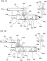
- the state switching valve 45 according to the modification shown in FIG. 5 is different from the state switching valve 24 in the above embodiment with regard to the positions of the test orifice position 24c and the complete interruption position 24d. That is, the state switching valve 45 is configured such that its position is switched between the actuator connection position 24a, the damping position 24b, the complete interruption position 24d and the test orifice position 24c in this order by sequentially changing the position of its spool (not shown) from the end where the control lever 24g is provided toward the end where the pilot pressure chamber 24e is provided. Note that the order of the actuator connection position, the damping position, the test orifice position and the complete interruption position is not limited to the orders described as examples for the state switching valve 24 and the state switching valve 45, and various modification can be made.
- FIGS. 6 are hydraulic circuit diagrams showing state switching valves according to other modifications, showing state switching valves (46, 47) of the first control system 13.
- FIG. 6A shows the hydraulic circuit diagram of the state switching valve 46
- FIG. 6B shown the hydraulic circuit diagram of the state switching valve 47. Note that the description of those elements configured in the same manner as the above embodiment is omitted by using the same reference numerals in FIGS. 6 , or by referring to the same reference numerals as in the above embodiment.
- the state switching valve 46 according to the modification shown in FIG. 6A is configured such that its position can be switched between the actuator connection position 24a, the damping position 24b and the test orifice position 24c.
- the state switching valve 46 is different from the state switching valve 24 described above in that it is not provided with the complete interruption position 24d.
- it is possible to implement a state switching valve 46 that is provided with only the actuator connection position 24a, the damping position 24b and the test orifice position 24c.
- the second control system 14 is also provided with a state switching valve configured in the same manner as the state switching valve 46.
- the state switching valve 47 according to the modification shown in FIG. 6B is configured such that its position can be switched between the actuator connection position 24a, the damping position 24b and the complete interruption position 24d.
- the second control system 14 is also provided with a state switching valve (this state switching valve as well is referred to as a "state switching valve 47") configured in the same manner as the state switching valve 47.
- the state switching valves (47, 47) are different from the state switching valves (24, 27) described above in that they are not provided with the test orifice position 24c.
- An aircraft actuator control apparatus provided with the state switching valves (47) is different from the aircraft actuator control apparatus 1 described above also in that it is not provided with the test orifice circuit.
- a performance test for the hydraulic circuit connecting to the state switching valve 47 and the actuator (11 or 12) is executed in the control system (13 or 14) corresponding to another actuator (the other of the actuators 11 and 12) that is different from the actuator (one of the actuators 11 and 12) that drives the control surface 100. Also, the above-mentioned performance test for the hydraulic circuit is executed by determining whether the control surface 100 is stopped.
- the state switching valves 47 that switch the operating state of the actuators (11, 12) are configured such that their position can be switched between the actuator connection position 24a, the damping position 24b, and the complete interruption position 24d that interrupts all of the ports (24h, 24h, 24i, 24i). Then, a performance test for the hydraulic circuit connecting to the state switching valve 47 and the actuator (11 or 12) is executed by determining whether the control surface 100 is stopped when the state switching valve 47 is switched to the complete interruption position 24d. Accordingly, a performance test for the hydraulic circuit connecting to the state switching valve 47 and the actuator (11 or 12) can be executed by a simple configuration achieved by providing the state switching valve 47 with the complete interruption position 24d.
- test pressure sensors respectively corresponding to the ports of the pairs of oil chambers (16a and 16b, 20a and 20b) of the actuators (11, 12), and therefore it is possible to suppress an increase in the number of sensors.
- signal wiring and a processing unit for determining whether the operation is normal by acquiring and processing signals from test pressure sensors will not be required in the first place, making it possible to suppress an increase in complexity of the mechanism for testing the operation of the control systems (13, 14) of the actuators (11, 12). This can lead to reduced costs.
- FIGS. 7 are hydraulic circuit diagrams showing state switching valves according to still other modifications, showing hydraulic circuit diagrams of state switching valves (48, 49) of the first control system 13.
- FIG. 7A shows the hydraulic circuit diagram of the state switching valve 48
- FIG. 7B shows the hydraulic circuit diagram of the state switching valve 49. Note that the description of those elements configured in the same manner as in the above-described embodiment is omitted by using the same reference numerals in FIGS. 7 , or by referring to the reference numerals used in the above-described embodiment.
- the state switching valve 48 according to the modification shown in FIG. 7A is different from the state switching valve 24 of the above-described embodiment with regard to the configuration of the damping position 24b.
- the state switching valve 48 is configured, when switched to the damping position 24b, to connect the pair of oil chambers (16a, 16b) of the first actuator 11 to the oil discharge system (in this modification, the supply/discharge oil passage 34b) of the control valve 23 via the orifices (24f, 24f).
- the actuator ports (24i, 24i) respectively connected to the supply/discharge oil passages (35a, 35b) are in communication with one of the control valve ports (24h, 24h) (the control valve port 24h connecting to the supply/discharge oil passage 34b) via the orifices 24f.
- the control valve 23 is maintained in the state of being switched to the first switching position 23b, and thereby the connected state between the supply/discharge oil passage 34b and the discharge oil passage 32 is maintained.
- the second control system 14 is also provided with a state switching valve (this state switching valve as well is referred to as a "state switching valve 48") configured in the same manner as the state switching valve 48.
- a state switching valve this state switching valve as well is referred to as a "state switching valve 48”
- the damping function of causing the actuators (11, 12) to follow an external force exerted on the control surface 100 is efficiently fulfilled.
- the state switching valve 49 according to the modification shown in FIG. 7B is different from the state switching valve 24 of the above-described embodiment in that it is further provided with a bypass position 49a.
- the state switching valve 49 is configured such that its position is switched between the actuator connection position 24a, the bypass position 49a, the damping position 24b, the test orifice position 24c and the complete interruption position 24d in this order by sequentially changing the position of its spool (not shown) from the end where the control lever 24g is provided toward the end where the pilot pressure chamber 24e is provided.
- the state switching valve 49 is configured such that its position can be switched between the actuator connection position 24a, the bypass position 49a and the damping position 24b by switching between the magnetized state and the demagnetized state of its solenoid and switching between the supply and the discharge of the pilot pressure oil. Also, the state switching valve 49 is configured such that its position can be switched between the test orifice position 24c and the complete interruption position 24d by manual operation of the control lever 24g.
- the bypass position 49a is configured as a position to provide communication between the pair of oil chambers (16a, 16b) by connection, without causing the oil chambers (16a, 16b) to pass through the orifices 24f as in the damping position 24b. That is, in a state where the state switching valve 49 is switched to the bypass position 49a, the actuator ports (24i, 24i) respectively connected to the supply/discharge oil passages (35a, 35b) are in communication with each other without passing through any orifice.
- the second control system 14 is also provided with a state switching valve configured in the same manner as the state switching valve 49. Note that the order of the actuator connection position, the bypass position, the damping position, the test orifice position and the complete interruption position are not limited to the orders described as an example for the state switching valve 49, and various modification can be made.
- the present invention can be widely applied as an aircraft actuator control apparatus that includes a plurality of hydraulically operated actuators that drive a control surface of an aircraft and a plurality of control systems that respectively controls the operation of the plurality of actuators.
- the present invention is not limited to the above-described embodiment, and all modifications, applications and equivalents thereof that fall within the claims, for which modifications and applications would become apparent by reading and understanding the present specification, are intended to be embraced therein.
Landscapes
- Engineering & Computer Science (AREA)
- Aviation & Aerospace Engineering (AREA)
- Physics & Mathematics (AREA)
- Fluid Mechanics (AREA)
- Automation & Control Theory (AREA)
- Manufacturing & Machinery (AREA)
- Transportation (AREA)
- Fluid-Pressure Circuits (AREA)
Description
- This application claims priority to Japanese Patent Application No.
2010-173503 - The present invention relates to an aircraft actuator control apparatus including a plurality of hydraulically operated actuators that drive a control surface of an aircraft and a plurality of control systems that respectively control the operation of the plurality of actuators.
- Conventionally, aircraft actuator control apparatuses are used that include a plurality of hydraulically operated actuators that drive a control surface of an aircraft and a plurality of control systems that respectively control the operation of the plurality of actuators. A known example of such an aircraft actuator control apparatus is the aircraft actuator control apparatus disclosed in
JP 2003-40199A - In the aircraft actuator control apparatus disclosed in
JP 2003-40199A - The above-described state switching valve is provided such that its position can be switched between a position to connect the actuator to the control valves such that pressure oil flows between each of the pair of oil chambers of the actuator and the control valves and a position in which the pressure oil discharged from the pair of oil chambers can pass through the above-described orifice. Note that in a state where the state switching valve is switched to a position in which pressure oil flows between the actuator and the control valves, the supply path and the discharge path of the pressure oil to and from the pair of oil chambers are switched by the control valves, and thereby the operation of the actuator is controlled. On the other hand, in a state where the state switching valve is switched to a position in which the pressure oil discharged from the pair of oil chambers can pass through the orifice, the pair of oil chambers are in communication via this orifice, and thereby the damping function is fulfilled.
- Also, the pressure oil is supplied to the plurality of actuators from the respective aircraft central hydraulic power sources that are configured as different systems. Then, if a loss or degradation in the function occurs in the hydraulic power source that supplies the pressure oil to one of the actuators, the state switching valve corresponding to that actuator is switched to the position to provide communication between the pair of oil chambers via the orifice. Accordingly, the above-described damping function is fulfilled, and thereby the actuator that experiences a degradation or the like in the function of the corresponding hydraulic power source operates so as to follow an external force exerted on the control surface. This can prevent an operation to impede the operation of an actuator for which a loss or the like in the function of the hydraulic power source has not occurred and prevent an abnormal operation, including, for example, excessive movement of the control surface, such as flutter.
US2006/0226285 discloses another example of an aircraft control apparatus and is regarded as the closest prior art. - In the aircraft actuator control apparatus disclosed in
JP 2003-40199A - As the above-described test, it is possible to perform a test in which test pressure sensors are installed respectively corresponding to the ports of a pair of oil chambers of an actuator and whether the operation is normal is determined based on the results of pressure measurement performed by the pressure sensors during operation of the actuator. However, to perform such a test, pressure sensors that are installed respectively corresponding to the ports of the pair of oil chambers of the actuator and that are used only for the test are required, leading to an increase in the number of sensors. Also, signal wiring and a processing unit are required for determining whether the operation is normal by acquiring and processing signals from the test pressure sensors. This increases the complexity of the test mechanism and also leads to increased costs. Furthermore, it is necessary to take into consideration the influences of variations that result from determining whether the operation is normal based on the results of measurements performed by the pressure sensors, including, for example, the influence of variations caused by different pressure measurement conditions and the influence of variations caused by measurement errors. This also poses the problem that it is difficult to obtain a highly reliably test result.
- In view of the foregoing circumstances, it is an object of the present invention to provide an aircraft actuator control apparatus (as defined by the features of
claim 1 and claim 5) with which it is possible to suppress an increase in the number of sensors and an increase in complexity of the mechanism for testing the operation of a control system that controls actuators, and also to increase the reliability of the test result. - According to a first feature of an aircraft actuator control apparatus of the present invention for achieving the above-described object, there is provided an aircraft actuator control apparatus including: a plurality of hydraulically operated actuators that drive a control surface of an aircraft; and a plurality of control systems that respectively control operation of the plurality of actuators, wherein each of the plurality of control systems includes: a control valve that controls operation of the corresponding actuator by switching a path of pressure oil that is supplied to and discharged from each of a pair of oil chambers of the actuator; a state switching valve that is installed between the control valve and the actuator so as to provide communication between the control valve and the actuator, that includes an orifice that can be in communication with the pair of oil chambers, and that switches an operating state of the actuator; and a test orifice circuit that includes a test orifice used for testing a performance of the orifice and that can be in communication with the actuator via the state switching valve, the state switching valve is provided such that its position can be switched between: an actuator connection position to connect the actuator to the control valve so as to allow the pressure oil to flow between each of the pair of oil chambers and the control valve; a damping position to allow the pressure oil discharged from each of the pair of oil chambers to pass through the orifice; and a test orifice position to provide communication between each of the pair of oil chambers and the test orifice circuit so as to allow the pressure oil discharged from each of the pair of oil chambers to pass through the test orifice, in a state where the control surface is driven by at least one of the plurality of actuators, a performance test for the orifice can be executed in the control system under test that corresponds to another one of the actuators that is different from the actuator that drives the control surface, and the performance test for the orifice can be executed by comparing, for the control system under test and the actuator corresponding thereto, an operating speed of the actuator when the state switching valve is switched to the damping position with an operating speed of the actuator when the state switching valve is switched to the test orifice position.
- With this configuration, the state switching valves that switch the operating state of the actuators are configured such that their positions can be switched between the actuator connection position, the damping position, and the test orifice position to provide communication between each of the actuators and the test orifice circuit including the test orifice. Then, a performance test for the orifice is executed by comparing the operating speed of the actuator when the state switching valve is switched to the damping position with the operating speed of the actuator when the state switching valve is switched to the test orifice position. Accordingly, it is not necessary to install test pressure sensors respectively corresponding to the ports of the pairs of oil chambers of the actuators, and therefore it is possible to suppress an increase in the number of sensors. Also, signal wiring and a processing unit for determining whether the operation is normal by acquiring and processing signals from test pressure sensors will not be required in the first place, making it possible to suppress an increase in complexity of the mechanism for testing the operation of the control systems of the actuators. This can lead to reduced costs. Furthermore, the test orifice serving as the reference for determining the normal operation can be directly used to determine whether the operation is normal, and therefore it is possible to obtain a highly reliably test result.
- Therefore, with this configuration, it is possible to provide an aircraft actuator control apparatus with which it is possible to suppress an increase in the number of sensors and an increase in complexity of the mechanism for testing the operation of the control systems that control the actuators, and also increase the reliability of test results.
- According to a second feature of the aircraft actuator control apparatus of the present invention, in the aircraft actuator control apparatus having the first feature, when switched to the damping position, the state switching valve connects the pair of oil chambers to each other so as to provide communication between the pair of oil chambers via the orifice, or connects the pair of oil chambers to an oil discharge system in the control valve via the orifice.
- With this configuration, in a state where the state the switching valves are switched to the damping position, each of the pairs of oil chambers are connected to each other via the orifice or connected to the oil discharge system. Accordingly, the damping function of causing the actuators to follow an external force exerted on the control surface is fulfilled efficiently. Accordingly, it is possible to achieve an aircraft actuator control apparatus with which it is possible to increase the reliability of a performance test for the orifice in the state switching valve that can efficiently fulfill the damping function, thus suppressing an increase in the number of sensors and an increase in complexity of the test mechanism.
- According to a third feature of the aircraft actuator control apparatus of the present invention, in the aircraft actuator control apparatus having the first or second feature, the state switching valve is provided with a control lever for switching between positions by manual operation, and an operation of switching to the test orifice position can be performed by manual operation of the control lever.
- With this configuration, the operation for switching to the test orifice position is performed by manual operation using the control lever. Accordingly, a performance test for the orifice can be easily and reliably executed by manual operation.
- According to a fourth feature of the aircraft actuator control apparatus of the present invention, in the aircraft actuator control apparatus having any one of the first to third features, the state switching valve is provided such that its position can also be switched to a complete interruption position where control valve ports in communication with the control valve, actuator ports in communication with the pair of oil chambers of the actuator, and test ports in communication with the test orifice circuit are all interrupted, in a state where the pressure oil is supplied to one of the plurality of actuators, a performance test for a hydraulic circuit connecting to the state switching valve and to another one of the actuators that is different from the actuator to which the pressure oil is supplied is executed in the control system under test that corresponds to that other one of the actuators, and the performance test for the hydraulic circuit can be executed by determining whether the control surface is stopped.
- With this configuration, the state switching valves are configured such that their positions can be switched to the complete interruption position to interrupt all ports, in addition to the actuator connection position, the damping position and the test orifice position. Then, a performance test for the hydraulic circuit connecting to the state switching valve and the actuator is executed by determining whether the control surface is stopped when the state switching valve is switched to the complete interruption position. Accordingly, in addition to a performance test for the orifice, a performance test for the hydraulic circuit connecting to the state switching valve and the actuator can also be executed by a simple configuration achieved by providing the state switching valves with the complete interruption position. This makes it possible to determine whether the operation is normal separately for each of the orifice and the hydraulic circuit that connects to the state switching valve and the actuator, thus obtaining an even more reliable test result.
- According to a fifth feature of an aircraft actuator control apparatus of the present invention for achieving the above-described object, there is provided an aircraft actuator control apparatus including: a plurality of hydraulically operated actuators that drive a control surface of an aircraft; and a plurality of control systems that respectively control operation of the plurality of actuators, wherein each of the plurality of control systems includes: a control valve that controls operation of the corresponding actuator by switching a path of pressure oil that is supplied to and discharged from each of a pair of oil chambers of the actuator; and a state switching valve that is installed between the control valve and the actuator so as to provide communication between the control valve and the actuator, that includes an orifice that can be in communication with the pair of oil chambers, and that switches an operating state of the actuator; the state switching valve is provided such that its position can be switched between: an actuator connection position to connect the actuator to the control valve so as to allow the pressure oil to flow between each of the pair of oil chambers and the control valve; a damping position to allow the pressure oil discharged from each of the pair of oil chambers to pass through the orifice; and a complete interruption position where control valve ports in communication with the control valve and actuator ports in communication with the pair of oil chambers of the actuator are all interrupted, by supply of the pressure oil to at least one of the plurality of actuators, a performance test for a hydraulic circuit connecting to the state switching valve and to another one of the actuators that is different from the actuator that drives the control surface can be executed in the control system under test that corresponds to that other one of the actuators, and the performance test for the hydraulic circuit can be executed by determining whether the control surface is stopped.
- With this configuration, the state switching valves that switch the operating state of the actuators is configured such that their position can be switched between the actuator connection position, the damping position, and the complete interruption position that interrupts all of ports. Then, a performance test for the hydraulic circuit connecting to the state switching valve and the actuator is executed by determining whether the control surface is stopped when the state switching valve is switched to the complete interruption position. Accordingly, a performance test for the hydraulic circuit connecting to the state switching valve and the actuator can be executed by a simple configuration achieved by providing the state switching valve with the complete interruption position. Accordingly, it is not necessary to install test pressure sensors respectively corresponding to the ports of the pairs of oil chambers of the actuators, and therefore it is possible to suppress an increase in the number of sensors. Also, signal wiring and a processing unit for determining whether the operation is normal by acquiring and processing signals from test pressure sensors will not be required in the first place, making it possible to suppress an increase in complexity of the mechanism for testing the operation of the control systems of the actuators. This can lead to reduced costs. Furthermore, whether the operation of the hydraulic circuit connecting to the state switching valve and the actuator is normal can be directly determined by forcefully interrupting all ports, and therefore it is possible to obtain a highly reliably test result.
- It should be appreciated that the above and other objects, and features and advantages of the present invention will become apparent from the following description taken in conjunction with the accompanying drawings.
-
-
FIG. 1 is a hydraulic circuit diagram schematically showing an aircraft actuator control apparatus according to an embodiment of the present invention. -
FIG. 2 is a hydraulic circuit diagram showing the details of part of the aircraft actuator control apparatus shown inFIG. 1 . -
FIG. 3A is a hydraulic circuit diagram illustrating an operation of a state switching valve of the aircraft actuator control apparatus shown inFIG. 2 . -
FIG. 3B is a hydraulic circuit diagram illustrating an operation of the state switching valve of the aircraft actuator control apparatus shown inFIG. 2 . -
FIG. 4A is a hydraulic circuit diagram illustrating an operation of the state switching valve of the aircraft actuator control apparatus shown inFIG. 2 . -
FIG. 4B is a hydraulic circuit diagram illustrating an operation of the state switching valve of the aircraft actuator control apparatus shown inFIG. 2 . -
FIG. 5 is a hydraulic circuit diagram showing a state switching valve according to a modification. -
FIG. 6A is a hydraulic circuit diagram showing a state switching valve according to a modification. -
FIG. 6B is a hydraulic circuit diagram showing a state switching valve according to a modification. -
FIG. 7A is a hydraulic circuit diagram showing a state switching valve according to a modification. -
FIG. 7B is a hydraulic circuit diagram showing a state switching valve according to a modification. - Hereinafter, an embodiment for carrying out the present invention will be described with reference to the accompanying drawings. It should be appreciated that this embodiment can be widely applied to an aircraft actuator control apparatus including a plurality of hydraulically operated actuators that drive a control surface of an aircraft and a plurality of control systems that respectively control the operation of the plurality of actuators.
-
FIG. 1 is a hydraulic circuit diagram schematically showing an aircraftactuator control apparatus 1 according to one embodiment of the present invention. The aircraft actuator control apparatus 1 (hereinafter, also simply referred to as a "control apparatus 1") includes a plurality of (in this embodiment, two) hydraulically operated actuators (11, 12) that drive acontrol surface 100 of an aircraft (not shown) and a plurality of control systems (13, 14) that respectively control the operation of the plurality of actuators (11, 12). Note that thecontrol surface 100 is a moving surface (flight control surface) of the aircraft, and may be configured, for example, as an aileron provided in the main wing, an elevator provided in the tailplane, a rudder provided in the vertical tail, or the like. - The
control apparatus 1 is provided with afirst actuator 11 and a second actuator 12 as the actuators (11, 12). Each of the first and second actuators (11, 12) is coupled to thecontrol surface 100 and configured as a cylinder mechanism that can independently drive thecontrol surface 100. - The
first actuator 11 is provided with arod 15, acylinder 16 through which therod 15 penetrates so as to be axially movable, and apiston 17 that is fixed to therod 15. The interior of thecylinder 16 is divided into a pair of oil chambers (16a, 16b) by thepiston 17. Thefirst actuator 11 is also provided with aposition sensor 18 for detecting the position of therod 15 with respect to thecylinder 16. The second actuator 12 is provided with arod 19, and acylinder 20 through which therod 19 penetrates so as to be axially movable, and apiston 21 that is fixed to therod 19. The interior of thecylinder 20 is divided into a pair of oil chambers (20a, 20b) by thepiston 21. The second actuator 12 is also provided with aposition sensor 22 for detecting the position of therod 19 with respect to thecylinder 20. - Further, the
control apparatus 1 is provided with afirst control system 13 and asecond control system 14 as the control systems (13, 14). Thefirst control system 13 is configured to provide communication between the pair of oil chambers (16a, 16b) of thefirst actuator 11 and each of a first systemhydraulic power source 101 and areservoir circuit 102. On the other hand, thesecond control system 14 is configured to provide communication between the pair of oil chambers (20a, 20b) of the second actuator 12 and each of a second systemhydraulic power source 103 and areservoir circuit 104. - Each of the first system
hydraulic power source 101 and the second systemhydraulic power source 103 is provided with a hydraulic pump that supplies pressure oil (working fluid), and is installed on the body side of the aircraft (not shown). Also, the first systemhydraulic power source 101 and the second systemhydraulic power source 103 are provided as systems that are independent of each other. Note that in the aircraft in which the above-described hydraulic power sources (101, 103) are installed, the first and second actuators (11, 12) that drive thecontrol surface 100 and actuators (not shown) that drive control surfaces (not shown) other than thecontrol surface 100 are operated by supply of pressure oil from each of the first systemhydraulic power source 101 and the second systemhydraulic power source 103. - The
reservoir circuit 102 includes a tank (not shown) into which pressure oil that is supplied as pressure oil from the first systemhydraulic power source 101 and is thereafter discharged from thefirst actuator 11 flows back, and thereservoir circuit 102 is configured to be in communication with the first systemhydraulic power source 101. Thereservoir circuit 104 that is configured as a system independent of thereservoir circuit 102 includes a tank (not shown) into which pressure oil that is supplied as pressure oil from the second systemhydraulic power source 103 and is thereafter discharged from the second actuator 12 flows back, and thereservoir circuit 104 is configured to be in communication with the second systemhydraulic power source 103. With this configuration, the pressure of the oil that has returned to thereservoir circuit 102 is raised by the first systemhydraulic power source 101, and the oil is supplied to thefirst actuator 11 via thefirst control system 13. On the other hand, the pressure of the oil that has returned to thereservoir circuit 104 is raised by the second systemhydraulic power source 103, and the oil is supplied to the second actuator 12 via thesecond control system 14. -
FIG. 2 is a hydraulic circuit diagram illustrating the details of part of thecontrol apparatus 1, showing thefirst control system 13 and thefirst actuator 11. Thefirst control system 13 shown inFIGS. 1 and2 includes acontrol valve 23, astate switching valve 24, asolenoid valve 25, check valves (29a, 29b), atest orifice circuit 30, asupply oil passage 31, adischarge oil passage 32, a pilotpressure oil passage 33, supply/discharge oil passages (34a, 34b, 35a, 35b), and so forth. Thesecond control system 14 shown inFIG. 1 includes acontrol valve 26, astate switching valve 27, asolenoid valve 28, check valves (not shown) configured in the same manner as the check valves (29a, 29b), a test orifice circuit (not shown) configured in the same manner as thetest orifice circuit 30, asupply oil passage 36, adischarge oil passage 37, a pilotpressure oil passage 38, supply/discharge oil passages (39a, 39b, 40a, 40b), and so forth. - The
supply oil passage 31 of thefirst control system 13 is an oil passage that connects the first systemhydraulic power source 101 to thecontrol valve 23 to supply the pressure oil from the first systemhydraulic power source 101. Also, thesupply oil passage 31 is provided with a filter 101a for removing foreign matter contained in the oil and acheck valve 101b that permits flow of pressure oil from the first systemhydraulic power source 101 and prevents flow of the oil in a direction flowing back to the first systemhydraulic power source 101. Thedischarge oil passage 32 of thefirst control system 13 is an oil passage that connects thecontrol valve 23 to thereservoir circuit 102 to discharge the oil discharged from thecontrol valve 23 to thereservoir circuit 102. Also, thedischarge oil passage 32 is provided with anaccumulator 102a including a relief valve. By provision of theaccumulator 102a in thedischarge oil passage 32, the pressure of the pressure oil in the circuit of thefirst control system 13 and thefirst actuator 11 on the upstream side of the accumulator 102a (the side opposite to the side in communication with the reservoir circuit 102) is maintained at a pressure equal to or greater than a relief pressure generated by the relief valve of theaccumulator 102a. - The
supply oil passage 36 of thesecond control system 14 is an oil passage that connects the second systemhydraulic power source 103 to thecontrol valve 26 to supply the pressure oil from the second systemhydraulic power source 103. Thesupply oil passage 36 is provided with a filter and a check valve (not shown) that are configured in the same manner as the filter 101a and thecheck valve 101b of thefirst control system 13. Thedischarge oil passage 37 of thesecond control system 14 is an oil passage that connects thecontrol valve 26 to thereservoir circuit 104 to discharge the oil discharged from thecontrol valve 26 to thereservoir circuit 104. Thedischarge oil passage 37 is provided with an accumulator (not shown) configured in the same manner as theaccumulator 102a of thefirst control system 13. - The supply/discharge oil passages (34a, 34b) of the
first control system 13 are provided as oil passages that connect thecontrol valve 23 to thestate switching valve 24 and through which the pressure oil discharged from the first systemhydraulic power source 101 and the pressure oil discharged to thereservoir circuit 102 flow. The supply/discharge oil passages (35a, 35b) of thefirst control system 13 are provided as oil passages that connect thestate switching valve 24 to thefirst actuator 11 and through which the pressure oil supplied to thefirst actuator 11 and the pressure oil discharged from thefirst actuator 11 flow. Note that the supply/discharge oil passage 35a is configured to connect to theoil chamber 16a, which is one of the pair of oil chambers (16a, 16b) of thefirst actuator 11, whereas the supply/discharge oil passage 35b is configured to connect to theother oil chamber 16b. - The supply/discharge oil passages (39a, 39b) of the
second control system 14 are provided as oil passages that connect thecontrol valve 26 to thestate switching valve 27 and through which the pressure oil discharged from the second systemhydraulic power source 103 and the pressure oil discharged to thereservoir circuit 104 flow. The supply/discharge oil passages (40a, 40b) of thesecond control system 14 are provided as oil passages that connect thestate switching valve 27 to the second actuator 12 and through which the pressure oil supplied to the second actuator 12 and the pressure oil discharged from the second actuator 12 flow. Note that the supply/discharge oil passage 40a is configured to connect to theoil chamber 20a, which is one of the pair of oil chambers (20a, 20b) of the second actuator 12, whereas the supply/discharge oil passage 40b is configured to connect to theother oil chamber 20b. - The pilot
pressure oil passage 33 of thefirst control system 13 is an oil passage that connects thepilot pressure chamber 24e of thestate switching valve 24 to thesolenoid valve 25 to supply and discharge pilot pressure oil for operating thestate switching valve 24. Thesolenoid valve 25 connects to thesupply oil passage 31 via theoil passage 33a and connects to thedischarge oil passage 32 via theoil passage 33b. As shown inFIGS. 1 and2 , in the magnetized state, for example, thesolenoid valve 25 is switched to asupply position 25a in which it connects theoil passage 33a to the pilotpressure oil passage 33 and allows the pilot pressure oil from the first systemhydraulic power source 101 to be supplied to thepilot pressure chamber 24e of thestate switching valve 24. On the other hand, in the demagnetized state, for example, thesolenoid valve 25 is switched to adischarge position 25b in which it interrupts theoil passage 33a and connects the pilotpressure oil passage 33 to theoil passage 33b. Accordingly, the pilot pressure oil supplied to thepilot pressure chamber 24e can be discharged to thereservoir circuit 102. - The pilot
pressure oil passage 38 of thesecond control system 14 is an oil passage that connects the pilot pressure chamber (not shown) of thestate switching valve 27 to thesolenoid valve 28 to supply and discharge pilot pressure oil for operating thestate switching valve 27. Thesolenoid valve 28 connects to thesupply oil passage 36 via theoil passage 38a and connects to thedischarge oil passage 37 via theoil passage 38b. As shown inFIG. 1 , in the magnetized state, for example, thesolenoid valve 28 is switched to asupply position 28a in which it connects theoil passage 38a to the pilotpressure oil passage 38 and allows the pilot pressure oil from the second systemhydraulic power source 103 to be supplied to the pilot pressure chamber of thestate switching valve 27. On the other hand, in the demagnetized state, for example, thesolenoid valve 28 is switched to adischarge position 28b in which it interrupts theoil passage 38a and connects the pilotpressure oil passage 38 to theoil passage 38b. Accordingly, the pilot pressure oil supplied to the pilot pressure chamber of thestate switching valve 27 can be discharged to thereservoir circuit 104. - The
check valve 29a of thefirst control system 13 is installed in anoil passage 41a connecting the supply/discharge oil passage 35a to theoil passage 33b, and is provided so as to permit flow of the pressure oil from the side of theoil passage 41a connecting to theoil passage 33b to the side thereof connecting to theoil passage 35a and prevent flow of the pressure oil in the opposite direction. This provides a configuration in which the pressure oil having a pressure greater than or equal to a predetermined relief pressure maintained by theaccumulator 102a can be introduced to one of the oil chambers, namely, theoil chamber 16a to which theoil passage 35a is connected, in the case where there is a reduction in pressure of the pressure oil in theoil chamber 16a. Thecheck valve 29b is installed in anoil passage 41b connecting the supply/discharge oil passage 35b to theoil passage 33b, and is provided so as to permit flow of the pressure oil from the side of theoil passage 41b connecting to theoil passage 33b to the side thereof connecting to theoil passage 35b and prevent flow of the pressure oil in the opposite direction. This provides a configuration in which the pressure oil having a pressure greater than or equal to a predetermined relief pressure maintained by theaccumulator 102a can be introduced to theother oil chamber 16b to which theoil passage 35b is connected, in the case where there is a reduction in pressure of the pressure oil in theoil chamber 16b. Although not shown, thesecond control system 14 is also provided with two check valves configured in the same manner as the check valves (29a, 29b) of thefirst control system 13. - The
control valve 23 of thefirst control system 13 is an electrohydraulic servo valve that controls the operation of thefirst actuator 11 by switching between the paths of the pressure oil that is supplied to and discharged from the pair of oil chambers (16a, 16b) of thefirst actuator 11. Thecontrol valve 23 is driven in accordance with a command signal from anactuator controller 42a that controls the operation of thefirst actuator 11. Theactuator controller 42a controls thefirst actuator 11 in accordance with a command signal from aflight controller 43 serving as a further superordinate computer that commands the operation of thecontrol surface 100. Note that theflight controller 43 may include, for example, a central processing unit (CPU), a memory, an interface, and so forth, which are not shown. - The
control valve 26 of thesecond control system 14 is an electrohydraulic servo valve that controls the operation of the second actuator 12 by switching between the paths of the pressure oil that is supplied to and discharged from the pair of oil chambers (20a, 20b) of the second actuator 12. Thecontrol valve 26 is driven in accordance with a command signal from anactuator controller 42b that controls the operation of the second actuator 12. Theactuator controller 42b controls the second actuator 12 in accordance with a command signal from theflight controller 43. - The
flight controller 43 is configured to receive input of a position detection signal for therod 15 that is detected by theposition sensor 18 of thefirst actuator 11 and a position detection signal for therod 19 that is detected by theposition sensor 22 of the second actuator 12. Theflight controller 43 controls the supply and discharge of pressure oil to and from the pair of oil chambers (16a, 16b) via theactuator controller 42a and thecontrol valve 23 so as to provide a feedback control of the position of therod 15 in accordance with the above-described position detection signal, thereby controlling the operation of thecontrol surface 100. Likewise, theflight controller 43 controls the supply and discharge of pressure oil to and from the pair of oil chambers (20a, 20b) via theactuator controller 42b and thecontrol valve 26 so as to provide a feedback control of the position of therod 19 in accordance with the above-described position detection signal, thereby controlling the operation of thecontrol surface 100. - As shown in
FIG. 2 , thecontrol valve 23 of thefirst control system 13 is provided such that its position can be proportionally switched between aneutral position 23a, afirst switching position 23b, and asecond switching position 23c. When switched to theneutral position 23a, thecontrol valve 23 interrupts thesupply oil passage 31 and thedischarge oil passage 32 from the supply/discharge oil passage (34a, 34b), thus maintaining a state where the supply and discharge to and from the pair of oil chambers (16a, 16b) are stopped and therod 15 of thefirst actuator 11 is stopped. - When the
control valve 23 is switched from theneutral position 23a to thefirst switching position 23b, thesupply oil passage 31 is connected to the supply/discharge oil passage 34a to supply the pressure oil to supplied to one of the actuators, namely, theoil chamber 16a, and thedischarge oil passage 32 is connected to the supply/discharge oil passage 34b to discharge the pressure oil from theother oil chamber 16b. On the other hand, when thecontrol valve 23 is switched from theneutral position 23a to thesecond switching position 23c, thesupply oil passage 31 is connected to the supply/discharge oil passage 34b to supply pressure oil to theoil chamber 16b, and thedischarge oil passage 32 is connected to the supply/discharge oil passage 34a to discharge the pressure oil from theoil chamber 16a. Note that in a state where thecontrol valve 23 is switched to thefirst switching position 23b and a state where thecontrol valve 23 is switched to thesecond switching position 23c, therod 15 moves in opposite directions and thus thecontrol surface 100 is also driven so as to operate in opposite directions. Thecontrol valve 26 of thesecond control system 14 is configured and operated in the same manner as thecontrol valve 23 of thefirst control system 13, and therefore the description thereof is omitted. - The
state switching valve 24 of thefirst control system 13 is installed between thecontrol valve 23 and thefirst actuator 11 so as to provide communication between thecontrol valve 23 and thefirst actuator 11. Thestate switching valve 24 includes anorifice 24f that can be in communication with the pair of oil chambers (16a, 16b) of thefirst actuator 11, and is configured as a valve that switches the operating state of thefirst actuator 11. Thestate switching valve 27 of thesecond control system 14 is installed between thecontrol valve 26 and the second actuator 12 so as to provide communication between thecontrol valve 26 and the second actuator 12. Thestate switching valve 27 includes an orifice (not shown) that can be in communication with the pair of oil chambers (20a, 20b) of the second actuator 12, and is configured as a valve that switches the operating state of the second actuator 12. - The
test orifice circuit 30 of thefirst control system 13 includes atest orifice 30a used for testing the performance of theorifice 24f of thestate switching valve 24, and is provided as a hydraulic circuit that can be in communication with thefirst actuator 11 via thestate switching valve 24. Thetest orifice circuit 30 is configured as a single oil passage whose exits on both ends respectively connect to test ports (24j, 24j), which will be described below, of thestate switching valve 24, and thetest orifice 30a is provided in the middle of this oil passage. Thetest orifice circuit 30 may be configured as a hydraulic circuit provided in a casing integrated with thestate switching valve 24, or may be configured as a hydraulic circuit provided in a casing separate from thestate switching valve 24. - The
test orifice 30a is configured as a portion of the oil passage containing thetest orifice circuit 30 and being in communication with the test ports (24j, 24j) of thestate switching valve 24, and that portion has a reduced cross sectional area so as to reduce the flow rate of the pressure oil flowing through the oil passage. Also, thetest orifice 30a is configured as an orifice having the same specifications as theorifice 24f of thestate switching valve 24. In other words, theorifice 24f and thetest orifice 30a have the same performance in their unused state immediately after installation. As the performance of theorifice 24f is degraded through use, there will be a difference in performance between theorifice 24f and thetest orifice 30a. For this reason, thecontrol apparatus 1 is configured to detect the degree of degradation of theorifice 24f through testing of the performance of theorifice 24f that can be compared with the performance of thetest orifice 30a as the reference. - The test orifice circuit (not shown) of the
second control system 14 includes a test orifice (not shown) used for a performance test for an orifice (not shown) of thestate switching valve 27, and is provided as a hydraulic circuit that can be in communication with the second actuator 12 via thestate switching valve 27. The test orifice of the test orifice circuit of thesecond control system 14 is configured as an orifice having the same specification as the orifice of thestate switching valve 27. Note that the test orifice circuit of thesecond control system 14 is configured in the same manner as thetest orifice circuit 30 of thefirst control system 13, and therefore the detailed description thereof is omitted. - The
state switching valve 24 of thefirst control system 13 will now be described in further details. Note that thestate switching valve 27 of thesecond control system 14 is configured in the same manner as thestate switching valve 24 of thefirst control system 13, and therefore the further detailed description of thestate switching valve 27 is omitted. - As shown in
FIG. 2 , thestate switching valve 24 is provided such that its position can be switched between anactuator connection position 24a, a dampingposition 24b, atest orifice position 24c and acomplete interruption position 24d.FIGS. 3 (FIGS. 3A, 3B ) andFIGS. 4 (FIGS. 4A, 4B ) are hydraulic circuit diagrams illustrating the operation of thestate switching valve 24, each showing thestate switching valve 24 and a hydraulic circuit located in the vicinity of thestate switching valve 24 inFIG. 2 . Note thatFIG. 3A shows a state where thestate switching valve 24 is switched to theactuator connection position 24a,FIG. 3B shows a state where thestate switching valve 24 is switched to the dampingposition 24b,FIG. 4A shows a state where thestate switching valve 24 is switched to thetest orifice position 24c, andFIG. 4B shows a state where thestate switching valve 24 is switched to thecomplete interruption position 24d. - Furthermore, as shown in
FIGS. 2 to 4 , thestate switching valve 24 is provided with thepilot pressure chamber 24e, theorifice 24f, acontrol lever 24g, control valve ports (24h, 24h), actuator ports (24i, 24i), the test ports (24j, 24j), and so forth. Note that thestate switching valve 24 is configured to be switched between the connected state and the interrupted state of the oil passages between the ports (24h, 24h, 24i, 24i, 24j, 24j) by changing the position of the spool (not shown) in its sleeve (not shown). Also, thestate switching valve 24 is configured such that its position is switched between theactuator connection position 24a, the dampingposition 24b, thetest orifice position 24c, and thecomplete interruption position 24d in this order by sequentially changing the position of its spool from the end where thecontrol lever 24g is provided toward the end where thepilot pressure chamber 24e is provided. - The
pilot pressure chamber 24e is an oil chamber to which pilot pressure oil is introduced via thesolenoid valve 25 and the pilotpressure oil passage 33. In a state where pressure oil has been supplied to thepilot pressure chamber 24e, thestate switching valve 24 is switched to theactuator connection position 24a by a biasing force exerted by the pilot pressure oil against the spring force of aspring 24k (seeFIG. 3A ). On the other hand, thestate switching valve 24 is switched to the dampingposition 24b by the spring force of thespring 24k as a result of the pilot pressure oil being discharged from thepilot pressure chamber 24e (seeFIG. 3B ). - The
orifice 24f is disposed in an oil passage that constitutes the dampingposition 24b of thestate switching valve 24 and that can provide communication between the supply/discharge oil passage 35a and the supply/discharge oil passage 35b. Also, theorifice 24f is provided, for example, in the oil passage that can provide communication between the supply/discharge oil passages (35a, 35b) as a notch configured as a portion having a reduced cross sectional area so as to reduce the flow rate of the pressure oil flowing from one of the supply/discharge oil passages (35a, 35b) to the other. - The
control lever 24g is a mechanism with which the operator (not shown) switches the position of thestate switching valve 24 by manual operation. The operation of switching the position of thestate switching valve 24 with thecontrol lever 24g is performed in a state where thesolenoid valve 25 is switched to thedischarge position 25b to discharge the pilot pressure oil from thepilot pressure chamber 24e and thestate switching valve 24 is thereby switched to the dampingposition 24b (the state shown inFIG. 3B ). - Further, the
control lever 24g is configured to switch the position of thestate switching valve 24 in two steps. In the first switching operation performed with thecontrol lever 24g, thestate switching valve 24 is switched from the dampingposition 24b to thetest orifice position 24c (seeFIG. 4A ). Then, in the second switching operation performed with thecontrol lever 24g, thestate switching valve 24 is switched from thetest orifice position 24c to thecomplete interruption position 24d (seeFIG. 4B ). Thus, thestate switching valve 24 is configured to perform the operation of switching to each of thetest orifice position 24c and thecomplete interruption position 24d through manual operation of thecontrol lever 24g. - Note that the
state switching valve 24 is switched to thetest orifice position 24c, for example, by manually urging thecontrol lever 24g toward thepilot pressure chamber 24e in the dampingposition 24b to move the spool position, causing the spool to stop against the sleeve or the like. Also, thestate switching valve 24 is switched to thecomplete interruption position 24d, for example, by manually rotating thecontrol lever 24g in the direction of rotation about the spool axis in thetest orifice position 24c and then further manually urging thecontrol lever 24f toward thepilot pressure chamber 24e to further move the spool position, causing the spool to stop against the sleeve or the like. - The control valve ports (24h, 24h) are provided as ports that are in communication with the
control valve 23, with one of the control valve ports (24h, 24h) being configured to connect to the supply/discharge oil passage 34a and the other being configured to connect to the supply/discharge oil passage 34b. The actuator ports (24i, 24i) are provided as ports that are in communication with the pair of oil chambers (16a, 16b) of thefirst actuator 11, with one of the actuator ports (24i, 24i) being configured to connect to the supply/discharge oil passage 35a and the other being configured to connect to the supply/discharge oil passage 35b. The test ports (24j, 24j) are provided as ports that are in communication with thetest orifice circuit 30, with each of the ports (24j, 24j) being configured to connect to exits on both ends of thetest orifice circuit 30. - The
actuator connection position 24a is configured as a position to connect thefirst actuator 11 to thecontrol valve 23 such that pressure oil flows between each of the pair of oil chambers (16a, 16b) of thefirst actuator 11 and thecontrol valve 23. That is, as shown inFIG. 3A , in a state where thestate switching valve 24 is switched to theactuator connection position 24a, the control valve ports (24h) respectively connected to the supply/discharge oil passages (34a, 34b) are in communication with the actuator ports (24i) respectively connected to the supply/discharge oil passages (35a, 35b). - In a state where the
state switching valve 24 is switched to theactuator connection position 24a, thecontrol valve 23 operates in accordance with a command signal from theflight controller 43 via theactuator controller 42a. Consequently, the supply/discharge of pressure oil to/from the pair of oil chambers (16a, 16b) of thefirst actuator 11 is controlled, and thereby the operation of thefirst actuator 11 is controlled. - The damping
position 24b is configured as a position to allow the pressure oil discharged from each of the pair of oil chambers (16a, 16b) of thefirst actuator 11 to pass through theorifice 24f and to provide communication between the pair of oil chambers (16a, 16b). That is, as shown inFIG. 3B , when switched to the dampingposition 24b, thestate switching valve 24 connects the pair of oil chambers (16a, 16b) to each other so as to provide communication between the pair of oil chambers (16a, 16b) via theorifice 24f. Note that in a state where thestate switching valve 24 is switched to the dampingposition 24b, the actuator ports (24i, 24i) respectively connected to the supply/discharge oil passages (35a, 35b) are in communication with each other via theorifice 24f. - For example, when a loss or degradation in the function of the first system
hydraulic power source 101 occurs, theactuator controller 42a demagnetizes thesolenoid valve 25 in accordance with a command signal from theflight controller 43. Consequently, thesolenoid valve 25 is switched to thedischarge position 25b to discharge the pilot pressure oil from thepilot pressure chamber 24e, and thestate switching valve 24 is switched to the dampingposition 24b by the spring force of thespring 24k. - When the
state switching valve 24 is switched to the dampingposition 24b, thefirst actuator 11 operates so as to follow an external force exerted on thecontrol surface 100 driven by the second actuator 12 (e.g., the driving force exerted by the second actuator 12). With the movement of therod 15 during this operation, the pressure oil flows between the pair of oil chambers (16a, 16b) through theorifice 24f, and the damping function by theorifice 24f is thus fulfilled. This prevents thefirst actuator 11 from operating to impede the operation of the second actuator 12 for which a loss or the like in the function of the second systemhydraulic power source 103 has not occurred in thecontrol apparatus 1. - When a loss or the like in the function occurs in both of the first system
hydraulic power source 101 and the second systemhydraulic power source 103, thestate switching valve 24 of thefirst control system 13 and thestate switching valve 27 of thesecond control system 14 are both switched to the damping position. In this case, thefirst actuator 11 and the second actuator 12 operate so as to follow an external force exerted on the control surface 100 (e.g., wind force exerted on the aircraft wing during flight). With the movement of the rods (15, 19) during this operation, the pressure oil flows between the pair of oil chambers (16a, 16b) and between the pair of oil chambers (20a, 20b) through the orifices, and thereby the damping function by the orifices is fulfilled. This can prevent an abnormal operation of thecontrol surface 100, including, for example, excessive movement of thecontrol surface 100 such as flutter. - The
test orifice position 24c is configured as a position to provide communication between each of the pair of oil chambers (16a, 16b) and thetest orifice circuit 30 so as to allow the pressure oil discharged from each of the pair of oil chambers (16a, 16b) of thefirst actuator 11 to pass through thetest orifice 30a. That is, as shown inFIG. 4A , when switched to thetest orifice position 24c, thestate switching valve 24 connects the pair of oil chambers (16a, 16b) so as to provide communication between the pair of oil chambers (16a, 16b) via thetest orifice 30a. Accordingly, in a state where thestate switching valve 24 is switched to thetest orifice position 24c, the actuator ports (24i, 24i) respectively connected to the supply/discharge oil passage (35a, 35b) are in communication with the test ports (24j, 24j) respectively connected to thetest orifice circuit 30. Note that the switching of the position of thestate switching valve 24 to thetest orifice position 24c is performed during a performance test for theorifice 24f as described below and is performed by manual operation of thecontrol lever 24g. - The
complete interruption position 24d is configured as a position to interrupt all of the ports of thestate switching valve 24, namely, the control valve ports (24h, 24h), the actuator ports (24i, 24i) and the test ports (24j, 24j). That is, as shown inFIG. 4B , when switched to thecomplete interruption position 24d, thestate switching valve 24 interrupts the connection between all of the ports (24h, 24h, 24i, 24i, 24j, 24j) and interrupts the supply/discharge oil passages (34a, 34b), the supply/discharge oil passages (35a, 35b), and thetest orifice circuit 30 from each other. Note that the switching of the position of thestate switching valve 24 to thecomplete interruption position 24d is performed during a performance test for a hydraulic circuit connecting to thestate switching valve 24 and thefirst actuator 11 as described below and is performed by manually operating thecontrol lever 24g. - Next, a performance test for the
orifice 24f in thefirst control system 13 and a performance test for a hydraulic circuit connecting to thestate switching valve 24 and thefirst actuator 11 in thefirst control system 13 will be described. In this embodiment, the hydraulic circuit connecting to thestate switching valve 24 and thefirst actuator 11 in thefirst control system 13 is configured as the hydraulic circuit 44 (seeFIG. 2 ), which includes the supply/discharge oil passages (35a, 35b) and the oil passages (41a, 41b) provided with the check valves (29a, 29b). Note that a performance test for the orifice in thesecond control system 14 and a performance test for the hydraulic circuit connecting to thestate switching valve 27 and the second actuator 12 in thesecond control system 14 are the same as the performance test for theorifice 24f in thefirst control system 13 and the performance test for thehydraulic circuit 44, and therefore the description thereof is omitted. - The performance test for the
orifice 24f, the performance test for the orifice in thesecond control system 14, the performance test for thehydraulic circuit 44, and the performance test for the hydraulic circuit connecting to thestate switching valve 27 and the second actuator 12 in thesecond control system 14 are executed in accordance with the operation performed by the test operator (not shown) and the control performed by theflight controller 43. As shown inFIG. 1 , in theflight controller 43, a performancetest execution portion 43a is composed of a CPU and a program stored in a memory, and the memory constitutes astorage portion 43b. - The performance
test execution portion 43a executes a performance test for theorifice 24f, a performance test for the orifice of thesecond control system 14, a performance test for thehydraulic circuit 44 and a performance test for the hydraulic circuit connecting to thestate switching valve 27 and the second actuator 12 in thesecond control system 14, in accordance with a command input operation performed by the test operator. Thestorage portion 43b stores the information necessary for the performance tests executed by the performancetest execution portion 43a and the information acquired during the performance tests executed by the performancetest execution portion 43a. Note that the results of testing executed by the performancetest execution portion 43a may be, for example, displayed on the screen of to a display device (not shown) connected to theflight controller 43. - The performance test for the
orifice 24f in thefirst control system 13 may be executed, for example, during aircraft maintenance work. To execute this test, for example, a command for executing the performance test for theorifice 24f is input into theflight controller 43 by an input operation by the test operator through an input device (for example, an input touch panel, an input switch, an input pointing device, or the like), which is not shown. Then, in accordance with a command from theflight controller 43, theactuator controller 42a demagnetizes thesolenoid valve 25 to switch thesolenoid valve 25 to thedischarge position 25b, and thereby the pilot pressure oil is discharged from thepilot pressure chamber 24e. Consequently, thestate switching valve 24 is switched to the dampingposition 24b. At this time, in thesecond control system 14, thesolenoid valve 28 is maintained in thesupply position 28a and thestate switching valve 27 is maintained in the actuator connection position. - In the above-described state, the
actuator controller 42b actuates thecontrol valve 26 to switch the paths of the pressure oil supplied to and discharged from each of the pair of oil chambers (20a, 20b) of the second actuator 12, in accordance with a command signal from the performancetest execution portion 43a of theflight controller 43. Consequently, the second actuator 12 is controlled to execute a predetermined test operation that has been previously set, and thecontrol surface 100 is driven by the operation of the second actuator 12. At this time, thestate switching valve 24 of thefirst control system 13 has been switched to the dampingposition 24a, and therefore thefirst actuator 11 operates so as to follow the driving force of the second actuator 12 that is exerted on thecontrol surface 100. Accordingly, the pressure oil discharged from the pair of oil chambers (16a, 16b) flows so as to pass through theorifice 24f, and thereby the damping function by theorifice 24f is fulfilled. - While the
first actuator 11 is operating so as to follow thecontrol surface 100 in a state where thestate switching valve 24 is in the dampingposition 24b, a position detection signal for therod 15 is input from theposition sensor 18 of thefirst actuator 11 to theflight controller 43. Further, theflight controller 43 is provided with a timer (not shown) for time measurement. Then, the operating speed of the first actuator 11 (i.e., the rate of displacement of therod 15 with respect to the cylinder 16) is continuously and repeatedly calculated in the performancetest execution portion 43a throughout the operation of thefirst actuator 11, in accordance with a result of position detection for therod 15 from theposition sensor 18 and a result of time measurement with the timer. The data of the operating speed of thefirst actuator 11 that has been obtained by the repeated calculations performed by the performancetest execution portion 43a throughout the operation of thefirst actuator 11 is stored in thestorage portion 43b, together with the time data obtained during the calculations (i.e., time data obtained during acquisition of each operating speed). Consequently, the performance data for the damping function by theorifice 24f during the performance test when thestate switching valve 24 is in the dampingposition 24b is acquired. - Upon completion of the above-described process, the
control lever 24g is operated by manual operation performed by the test operator, and thereby thestate switching valve 24 is switched from the dampingposition 24b to thetest orifice position 24c (seeFIG. 4A ). Note that, at the time of switching thecontrol lever 24g by manual operation, a guidance may be provided by theflight controller 43 in thecontrol apparatus 1. In this case, for example, a message indicating the completion of acquisition of the operating speed data for thefirst actuator 11 in the dampingposition 24a may be displayed on the screen of a display device connected to theflight controller 43, under the control by theflight controller 43. Then, the test operator that has acknowledged the above-described message may operate thecontrol lever 24g, and thereafter a command to continue the testing may be input into theflight controller 43 by an input operation performed by the test operator through the above-described input device. - As described above, when the
state switching valve 24 is switched from the dampingposition 24b to thetest orifice position 24c, the performance test is continued in accordance with a command signal from the performancetest execution portion 43a of theflight controller 43. At this time, in thesecond control system 14, thesolenoid valve 28 is maintained in thesupply position 28a and thestate switching valve 27 is maintained in the actuator connection position. Then, theactuator controller 42b actuates thecontrol valve 26 in accordance with a command signal from the performancetest execution portion 43a, thus switching the paths of the pressure oil supplied to and discharged from each of the pair of oil chambers (20a, 20b) of the second actuator 12. - As described above, the second actuator 12 is controlled to execute a predetermined test operation that is the same as the test operation executed in a state where the
state switching valve 24 is in the dampingposition 24b, and thecontrol surface 100 is driven by the operation of the second actuator 12. At this time, thestate switching valve 24 of thefirst control system 13 has been switched to thetest orifice position 24c, and therefore thefirst actuator 11 operates so as to follow the driving force of the second actuator 12 that is exerted on thecontrol surface 100. Accordingly, the pressure oil discharged from the pair of oil chambers (16a, 16b) flows so as to pass through thetest orifice 30a, and thereby the damping function by thetest orifice 30a is fulfilled. - While the
first actuator 11 is operating so as to follow thecontrol surface 100 in a state where thestate switching valve 24 is in thetest orifice position 24c, a position detection signal for therod 15 is input from theposition sensor 18 of thefirst actuator 11 to theflight controller 43. Then, the operating speed of the first actuator 11 (i.e., the rate of displacement of therod 15 with respect to the cylinder 16) is continuously and repeatedly calculated in the performancetest execution portion 43a throughout the operation of thefirst actuator 11, in accordance with a result of position detection for therod 15 from theposition sensor 18 and a result of time measurement with the timer of theflight controller 43. The data of the operating speed of thefirst actuator 11 that has been obtained by the repeated calculations performed by the performancetest execution portion 43a throughout the operation of thefirst actuator 11 is stored in thestorage portion 43b, together with the time data obtained during the calculations (i.e., time data obtained during acquisition of each operating speed). Consequently, the performance data for the damping function by thetest orifice 30a during the performance test when thestate switching valve 24 is in thetest orifice position 24c is acquired. - Upon completion of the above-described process, the operating speed of the
first actuator 11 when thestate switching valve 24 is in the dampingposition 24b is compared with the operating speed of thefirst actuator 11 when thestate switching valve 24 is in thetest orifice position 24c in the performancetest execution portion 43a. At this time, the comparison of the operating speeds of thefirst actuator 11 is carried out, taking into consideration the change corresponding to the elapsed time since the start of operation of thefirst actuator 11. For example, the operating speed of thefirst actuator 11 in the dampingposition 24b is compared with the operating speed of thefirst actuator 11 in thetest orifice position 24c at the timing at which the elapsed time since the start of operation of thefirst actuator 11 is the same. Then, the comparison between the operating speeds is performed over a period extending from the start to the end of operation of thefirst actuator 11. - From the above-described comparison, for example, the performance
test execution portion 43a determines whether the speed gap (the value of the amount of deviation between the operating speeds) between the operating speed of thefirst actuator 11 in the dampingposition 24b and the operating speed of thefirst actuator 11 in thetest orifice position 24c exceeds a predetermined threshold. If there is any operating speed data in which the above-described speed gap exceeds the predetermined threshold from the start to the end of operation of thefirst actuator 11, the performancetest execution portion 43a may determine, for example, that there is the possibility that the performance degradation of theorifice 24f proceeds to impair the normal damping function, and may display the result of determination on the screen of the display device as a test result. - Note that the performance
test execution portion 43a may display a different form of indication on the screen of the display device as a test result, rather than performing the above-described determination. For example, it is possible to make a graph on which the change in operating speed of thefirst actuator 11 in the dampingposition 24b and the change in operating speed of thefirst actuator 11 in thetest orifice position 24c are superimposed on the same time axis representing the elapsed time since the start of operation of thefirst actuator 11 and display the graph on the screen of the display device as a comparison result. As the result of comparison between the operating speed of thefirst actuator 11 in the dampingposition 24b and the operating speed of thefirst actuator 11 in thetest orifice position 24c, if theflight controller 43 or the test operator determines that there is the possibility that the performance degradation of theorifice 24f proceeds to impair the normal damping function, measures such as replacement of thestate switching valve 24 will be taken. - As described above, in the
control apparatus 1, in a state where thecontrol surface 100 is driven by the second actuator 12, which is one of the plurality of actuators (11, 12), a performance test for theorifice 24f is executed in thefirst control system 13 under test that corresponds to the otherfirst actuator 11, which is different from the second actuator 12 that drives thecontrol surface 100. Then, the performance test for theorifice 24f in thecontrol apparatus 1 is executed by comparing the operating speed of thefirst actuator 11 when thestate switching valve 24 is switched to the dampingposition 24b with the operating speed of thefirst actuator 11 when thestate switching valve 24 is switched to thetest orifice position 24c for thefirst control system 13 under test and thefirst actuator 11 corresponding to thefirst control system 13. - Although not described in detail in this embodiment due to redundancy with the description of the performance test for the
orifice 24f of thefirst control system 13, a performance test for the orifice of thesecond control system 14 is executed in the same manner. That is, in thecontrol apparatus 1, in a state where thecontrol surface 100 is driven by thefirst actuator 11, which is one of the plurality of actuators (11, 12), a performance test for theorifice 24f is executed in thesecond control system 14 under test that corresponds to the other second actuator 12, which is different from thefirst actuator 11 that drives thecontrol surface 100. Then, the performance test for the orifice of thesecond control system 14 in thecontrol apparatus 1 is executed by comparing the operating speed of the second actuator 12 when thestate switching valve 27 is switched to the damping position with the operating speed of the second actuator 12 when thestate switching valve 27 is switched to the test orifice position for thesecond control system 14 under test and the second actuator 12 corresponding to thesecond control system 14. - Next, a performance test for the
hydraulic circuit 44 of thefirst control system 13 will be described. The performance test for thehydraulic circuit 44 is executed during aircraft maintenance work, for example. At the time of execution of this test, for example, a command for execution of the performance test for thehydraulic circuit 44 is input into theflight controller 43 by an input operation performed by the test operator through the above-described input device. Then, in accordance with a command from theflight controller 43, theactuator controller 42a demagnetizes thesolenoid valve 25 to switch thesolenoid valve 25 to thedischarge position 25b, and thereby the pilot pressure oil is discharged from thepilot pressure chamber 24e. Consequently, thestate switching valve 24 is in the state of being switched to the dampingposition 24b. At this time, in thesecond control system 14, thesolenoid valve 28 is maintained in thesupply position 28a and thestate switching valve 27 is maintained in the actuator connection position. - In the above-described state, the
control lever 24g is operated by manual operation performed by the test operator, and thereby thestate switching valve 24 is switched from the dampingposition 24b via thetest orifice position 24c to thecomplete interruption position 24d (seeFIG. 4B ). When thestate switching valve 24 is switched to thecomplete interruption position 24d, the performance test is continued in accordance with a command signal from the performancetest execution portion 43a of theflight controller 43. Then, theactuator controller 42b actuates thecontrol valve 26 in accordance with a command signal from the performancetest execution portion 43a, and thereby the paths of the pressure oil supplied to and discharged from each of the pair of oil chambers (20a, 20b) in the second actuator 12. - As described above, the second actuator 12 operates so as to drive the
control surface 100. However, thestate switching valve 24 of thefirst control system 13 is switched to thecomplete interruption position 24d at this time, and therefore, if thehydraulic circuit 44 is operating normally, thefirst actuator 11 will not operate so as to follow the driving force of the second actuator 12 that is exerted on thecontrol surface 100 and will remain stopped. Accordingly, if thehydraulic circuit 44 operates normally, thecontrol surface 100 will also remain stopped. - On the other hand, if any abnormality such as a failure occurs in the
hydraulic circuit 44, for example, in the case where leakage or the like occurs in at least one of the check valves (29a, 29b), the normal operation of thehydraulic circuit 44 cannot be ensured. In such a case, for example, thefirst actuator 11 operates so as to gradually follow the driving force of the second actuator 12 that is exerted on thecontrol surface 100. Accordingly, thecontrol surface 100 cannot be maintained in the stopped state and thus will move. Therefore, in the above-described performance test for thehydraulic circuit 44, whether the normal operation of thehydraulic circuit 44 is ensured is checked by determining whether thecontrol surface 100 is stopped. If it is determined that the normal operation of thehydraulic circuit 44 is not ensured, measures such as replacement of the check valves (29a, 29b) will be taken. - Note that whether the
control surface 100 is stopped may be determined by the test operator by visual confirmation, or may be determined by theflight controller 43 with the performancetest execution portion 43a. In the case where whether thecontrol surface 100 is stopped is determined by theflight controller 43, a position detection signal for therod 15 is input into theflight controller 43 from theposition sensor 18 of thefirst actuator 11 while thecontrol valve 26 is operating in accordance with a command signal from the performancetest execution portion 43a and the supply and discharge paths of the pressure oil to and from the second actuator 12 are being switched. Then, the performancetest execution portion 43a determines, for example, whether the value of variation of a result of position detection for therod 15 falls within a predetermined threshold range throughout operation of thecontrol valve 26. If the value of variation of a result of position detection for therod 15 is smaller than or equal to the predetermined threshold, it is determined that thecontrol surface 100 is stopped. If the value exceeds the predetermined threshold, it is determined that thecontrol surface 100 is moving. The result of this determination is displayed on the screen of the display device as a test result. In addition, in this case, a graph of results of position detection for therod 15 during operation of thecontrol valve 26 may also be displayed on the screen of the display device. - As described above, in the
control apparatus 1, in a state where pressure oil is supplied to the second actuator 12, which is one of the plurality of actuators (11, 12), a performance test for thehydraulic circuit 44 is executed in thefirst control system 13 under test that corresponds to the otherfirst actuator 11, which is different from the second actuator 12 to which the pressure oil is supplied. Then, the performance test for thehydraulic circuit 44 in thecontrol apparatus 1 is executed by determining whether thecontrol surface 100 is stopped. - As described above, with the
control apparatus 1, the state switching valves (24, 27) that switch the operating state of the actuators (11, 12) are configured such that their positions can be switched between the actuator connection position, the damping position, and the test orifice position to provide communication between each of the actuators and the test orifice circuit including the test orifice. Then, a performance test for the orifice is executed by comparing the operating speed of the actuator (11 or 12) when the state switching valve (24 or 27) is switched to the damping position with the operating speed of the actuator (11 or 12) when the state switching valve (24 or 27) is switched to the test orifice position. Accordingly, it is not necessary to install test pressure sensors respectively corresponding to the ports of the pairs of oil chambers (16a and 16b, 20a and 20b) of the actuators (11, 12), and therefore it is possible to suppress an increase in the number of sensors. Also, signal wiring and a processing unit for determining whether the operation is normal by acquiring and processing signals from test pressure sensors will not be required in the first place, making it possible to suppress an increase in complexity of the mechanism for testing the operation of the control systems (13, 14) of the actuators (11, 12). This can lead to reduced costs. Furthermore, the test orifice serving as the reference for determining the normal operation can be directly used to determine whether the operation is normal, and therefore it is possible to obtain a highly reliably test result. - Therefore, according to this embodiment, it is possible to provide an aircraft
actuator control apparatus 1 with which it is possible to suppress an increase in the number of sensors and an increase in complexity of the mechanism for testing the operation of the control systems (13, 14) that control the actuators (11, 12), and also increase the reliability of test results. - With the
control apparatus 1, in a state where the state the switching valves (24, 27) are switched to the damping position, each of the pairs of oil chambers (16a and 16b, 20a and 20b) are connected to each other via the orifice. Accordingly, the damping function of causing the actuators (11, 12) to follow an external force exerted on thecontrol surface 100 is fulfilled efficiently. Accordingly, it is possible to achieve an aircraftactuator control apparatus 1 with which it is possible to increase the reliability of a performance test for the orifice in the state switching valve (24, 27) that can efficiently fulfill the damping function, thus suppressing an increase in the number of sensors and an increase in complexity of the test mechanism. - With the
control apparatus 1, the operation for switching to the test orifice position is performed by manual operation using the control lever in the switching valves (24, 27). Accordingly, a performance test for the orifice can be easily and reliably executed by manual operation. - With the
control apparatus 1, the state switching valves (24, 27) are configured such that their positions can be switched to the complete interruption position to interrupt all ports, in addition to the actuator connection position, the damping position and the test orifice position. Then, a performance test for the hydraulic circuit connecting to the state switching valve (24 or 27) and the actuator (11 or 12) is executed by determining whether thecontrol surface 100 is stopped when the state switching valve (24 or 27) is switched to the complete interruption position. Accordingly, in addition to a performance test for the orifice, a performance test for the hydraulic circuit connecting to the state switching valve (24 or 27) and the actuator (11 or 12) can also be executed by a simple configuration achieved by providing the state switching valves (24, 27) with the complete interruption position. This makes it possible to determine whether the operation is normal separately for each of the orifice and the hydraulic circuit that connects to the state switching valve (24 or 27) and the actuator (11 or 12), thus obtaining an even more reliable test result. - Although an embodiment of the present invention has been described thus far, the present invention is not limited to the above-described embodiment, and various modifications may be made within the scope recited in the claims. For example, the following modifications are possible.
- (1) Although the above embodiment has been described taking, as an example, an aircraft actuator control apparatus including two actuators and two control systems that respectively control the operation of the two actuators, this need not be the case. It is also possible to implement an aircraft actuator control apparatus including three or more actuators and three or more control systems that respectively control the operation of the three or more actuators. In this case as well, as in the above embodiment, each of the control systems includes a control valve, a state switching valve and a test orifice circuit. Also, in a state where a control surface is driven by at least one of the three or more actuators, a performance test for an orifice is executed in the control system under test that corresponds to another actuator that is different from the actuator that drives the control surface. Further, in a state where pressure oil is supplied to at least one of the three or more actuators, a performance test for a hydraulic circuit connecting to the state switching valve and the actuator is executed in the control system under test that corresponds to another actuator that is different from the actuator to which the pressure oil is supplied.
- (2) Although the above embodiment has been described taking, as an example, a state switching valve configured such that its position is switched between the actuator connection position, the damping position, the test orifice position, and the complete interruption position in this order by sequentially changing the position of its spool from the end where the control lever is provided toward the end where the pilot pressure chamber is provided, this need not be the case.
FIG. 5 is a hydraulic circuit diagram showing a state switching valve according to a modification, showing astate switching valve 45 of thefirst control system 13. Note that the description of those elements configured in the same manner as in the above-described embodiment is omitted by using the same reference numerals inFIG. 5 , or by referring to the reference numerals used in the above-described embodiment. Although not shown, in this modification, thesecond control system 14 is also provided with a state switching valve configured in the same manner as thestate switching valve 45. - The
state switching valve 45 according to the modification shown inFIG. 5 is different from thestate switching valve 24 in the above embodiment with regard to the positions of thetest orifice position 24c and thecomplete interruption position 24d. That is, thestate switching valve 45 is configured such that its position is switched between theactuator connection position 24a, the dampingposition 24b, thecomplete interruption position 24d and thetest orifice position 24c in this order by sequentially changing the position of its spool (not shown) from the end where thecontrol lever 24g is provided toward the end where thepilot pressure chamber 24e is provided. Note that the order of the actuator connection position, the damping position, the test orifice position and the complete interruption position is not limited to the orders described as examples for thestate switching valve 24 and thestate switching valve 45, and various modification can be made.
(3)FIGS. 6 (FIGS. 6A, 6B ) are hydraulic circuit diagrams showing state switching valves according to other modifications, showing state switching valves (46, 47) of thefirst control system 13.FIG. 6A shows the hydraulic circuit diagram of thestate switching valve 46, andFIG. 6B shown the hydraulic circuit diagram of thestate switching valve 47. Note that the description of those elements configured in the same manner as the above embodiment is omitted by using the same reference numerals inFIGS. 6 , or by referring to the same reference numerals as in the above embodiment. - The
state switching valve 46 according to the modification shown inFIG. 6A is configured such that its position can be switched between theactuator connection position 24a, the dampingposition 24b and thetest orifice position 24c. However, thestate switching valve 46 is different from thestate switching valve 24 described above in that it is not provided with thecomplete interruption position 24d. Thus, it is possible to implement astate switching valve 46 that is provided with only theactuator connection position 24a, the dampingposition 24b and thetest orifice position 24c. Although not shown, in this modification, thesecond control system 14 is also provided with a state switching valve configured in the same manner as thestate switching valve 46. - The
state switching valve 47 according to the modification shown inFIG. 6B is configured such that its position can be switched between theactuator connection position 24a, the dampingposition 24b and thecomplete interruption position 24d. Although not shown, thesecond control system 14 is also provided with a state switching valve (this state switching valve as well is referred to as a "state switching valve 47") configured in the same manner as thestate switching valve 47. However, the state switching valves (47, 47) are different from the state switching valves (24, 27) described above in that they are not provided with thetest orifice position 24c. An aircraft actuator control apparatus provided with the state switching valves (47) is different from the aircraftactuator control apparatus 1 described above also in that it is not provided with the test orifice circuit. In this modification, by supply of pressure oil to one of the plurality of actuators (11, 12), a performance test for the hydraulic circuit connecting to thestate switching valve 47 and the actuator (11 or 12) is executed in the control system (13 or 14) corresponding to another actuator (the other of theactuators 11 and 12) that is different from the actuator (one of theactuators 11 and 12) that drives thecontrol surface 100. Also, the above-mentioned performance test for the hydraulic circuit is executed by determining whether thecontrol surface 100 is stopped. - According to this modification, the
state switching valves 47 that switch the operating state of the actuators (11, 12) are configured such that their position can be switched between theactuator connection position 24a, the dampingposition 24b, and thecomplete interruption position 24d that interrupts all of the ports (24h, 24h, 24i, 24i). Then, a performance test for the hydraulic circuit connecting to thestate switching valve 47 and the actuator (11 or 12) is executed by determining whether thecontrol surface 100 is stopped when thestate switching valve 47 is switched to thecomplete interruption position 24d. Accordingly, a performance test for the hydraulic circuit connecting to thestate switching valve 47 and the actuator (11 or 12) can be executed by a simple configuration achieved by providing thestate switching valve 47 with thecomplete interruption position 24d. Accordingly, it is not necessary to install test pressure sensors respectively corresponding to the ports of the pairs of oil chambers (16a and 16b, 20a and 20b) of the actuators (11, 12), and therefore it is possible to suppress an increase in the number of sensors. Also, signal wiring and a processing unit for determining whether the operation is normal by acquiring and processing signals from test pressure sensors will not be required in the first place, making it possible to suppress an increase in complexity of the mechanism for testing the operation of the control systems (13, 14) of the actuators (11, 12). This can lead to reduced costs. Furthermore, whether the operation of the hydraulic circuit connecting to thestate switching valve 47 and the actuator (11 or 12) is normal can be directly determined by forcefully interrupting all of the ports (24h, 24h, 24i, 24i), and therefore it is possible to obtain a highly reliably test result.
(4)FIGS. 7 (FIGS. 7A and 7B ) are hydraulic circuit diagrams showing state switching valves according to still other modifications, showing hydraulic circuit diagrams of state switching valves (48, 49) of thefirst control system 13.FIG. 7A shows the hydraulic circuit diagram of thestate switching valve 48, andFIG. 7B shows the hydraulic circuit diagram of thestate switching valve 49. Note that the description of those elements configured in the same manner as in the above-described embodiment is omitted by using the same reference numerals inFIGS. 7 , or by referring to the reference numerals used in the above-described embodiment. - The
state switching valve 48 according to the modification shown inFIG. 7A is different from thestate switching valve 24 of the above-described embodiment with regard to the configuration of the dampingposition 24b. Thestate switching valve 48 is configured, when switched to the dampingposition 24b, to connect the pair of oil chambers (16a, 16b) of thefirst actuator 11 to the oil discharge system (in this modification, the supply/discharge oil passage 34b) of thecontrol valve 23 via the orifices (24f, 24f). That is, in a state where thestate switching valve 48 is switched to the dampingposition 24b, the actuator ports (24i, 24i) respectively connected to the supply/discharge oil passages (35a, 35b) are in communication with one of the control valve ports (24h, 24h) (thecontrol valve port 24h connecting to the supply/discharge oil passage 34b) via theorifices 24f. Note that in a state where thestate switching valve 48 is switched to the dampingposition 24b, thecontrol valve 23 is maintained in the state of being switched to thefirst switching position 23b, and thereby the connected state between the supply/discharge oil passage 34b and thedischarge oil passage 32 is maintained. - Although not shown, in this modification, the
second control system 14 is also provided with a state switching valve (this state switching valve as well is referred to as a "state switching valve 48") configured in the same manner as thestate switching valve 48. According to this modification, as in the above-described embodiment, in a state where thestate switching valves 48 are switched to the dampingposition 24b, the damping function of causing the actuators (11, 12) to follow an external force exerted on thecontrol surface 100 is efficiently fulfilled. - The
state switching valve 49 according to the modification shown inFIG. 7B is different from thestate switching valve 24 of the above-described embodiment in that it is further provided with abypass position 49a. Thestate switching valve 49 is configured such that its position is switched between theactuator connection position 24a, thebypass position 49a, the dampingposition 24b, thetest orifice position 24c and thecomplete interruption position 24d in this order by sequentially changing the position of its spool (not shown) from the end where thecontrol lever 24g is provided toward the end where thepilot pressure chamber 24e is provided. Further, thestate switching valve 49 is configured such that its position can be switched between theactuator connection position 24a, thebypass position 49a and the dampingposition 24b by switching between the magnetized state and the demagnetized state of its solenoid and switching between the supply and the discharge of the pilot pressure oil. Also, thestate switching valve 49 is configured such that its position can be switched between thetest orifice position 24c and thecomplete interruption position 24d by manual operation of thecontrol lever 24g. - Furthermore, the
bypass position 49a is configured as a position to provide communication between the pair of oil chambers (16a, 16b) by connection, without causing the oil chambers (16a, 16b) to pass through theorifices 24f as in the dampingposition 24b. That is, in a state where thestate switching valve 49 is switched to thebypass position 49a, the actuator ports (24i, 24i) respectively connected to the supply/discharge oil passages (35a, 35b) are in communication with each other without passing through any orifice. Although not shown, in this embodiment, thesecond control system 14 is also provided with a state switching valve configured in the same manner as thestate switching valve 49. Note that the order of the actuator connection position, the bypass position, the damping position, the test orifice position and the complete interruption position are not limited to the orders described as an example for thestate switching valve 49, and various modification can be made. - The present invention can be widely applied as an aircraft actuator control apparatus that includes a plurality of hydraulically operated actuators that drive a control surface of an aircraft and a plurality of control systems that respectively controls the operation of the plurality of actuators. The present invention is not limited to the above-described embodiment, and all modifications, applications and equivalents thereof that fall within the claims, for which modifications and applications would become apparent by reading and understanding the present specification, are intended to be embraced therein.
Claims (6)
- An aircraft actuator control apparatus (1) comprising: a plurality of hydraulically operated actuators (11, 12) that drive a control surface (100) of an aircraft; and a plurality of control systems (13, 14) that respectively control operation of the plurality of actuators (11, 12),
wherein each of the plurality of control systems (13, 14) comprises:a control valve (23, 26) that controls operation of the corresponding actuator (11, 12) by switching a path of pressure oil that is supplied to and discharged from each of a pair of oil chambers of the actuator (11, 12);a state switching valve (24, 27) that is installed between the control valve (23, 26) and the actuator (11, 12) so as to provide communication between the control valve (23, 26) and the actuator (11, 12), that includes an orifice that can be in communication with the pair of oil chambers, and that switches an operating state of the actuator (11, 12); anda test orifice circuit that includes a test orifice used for testing a performance of the orifice and that can be in communication with the actuator (11, 12) via the state switching valve (24, 27),the state switching valve (24, 27) is provided such that its position can be switched between:an actuator connection position to connect the actuator (11, 12) to the control valve (23, 26) so as to allow the pressure oil to flow between each of the pair of oil chambers and the control valve (23, 26);a damping position to allow the pressure oil discharged from each of the pair of oil chambers to pass through the orifice; anda test orifice position to provide communication between each of the pair of oil chambers and the test orifice circuit so as to allow the pressure oil discharged from each of the pair of oil chambers to pass through the test orifice,in a state where the control surface (100) is driven by at least one of the plurality of actuators (11, 12), a performance test for the orifice can be executed in the control system under test that corresponds to another one of the actuators that is different from the actuator that drives the control surface (100), andthe performance test for the orifice can be executed by comparing, for the control system under test and the actuator corresponding thereto, an operating speed of the actuator when the state switching valve (24, 27) is switched to the damping position with an operating speed of the actuator when the state switching valve (24, 27) is switched to the test orifice position. - The aircraft actuator control apparatus according to claim 1,
wherein, when switched to the damping position, the state switching valve (24, 27) connects the pair of oil chambers to each other so as to provide communication between the pair of oil chambers via the orifice, or connects the pair of oil chambers to an oil discharge system in the control valve via the orifice. - The aircraft actuator control apparatus according to claim 1 or 2,
wherein the state switching valve (24, 27) is provided with a control lever for switching between positions by manual operation, and
an operation of switching to the test orifice position can be performed by manual operation of the control lever. - The aircraft actuator control apparatus according to any one of claims 1 to 3,
wherein the state switching valve (24, 27) is provided such that its position can also be switched to a complete interruption position where all control valve ports in communication with the control valve (23, 26), actuator ports in communication with the pair of oil chambers of the actuator (11, 12), and test ports in communication with the test orifice circuit are all interrupted,
in a state where the pressure oil is supplied to one of the plurality of actuators (11, 12), a performance test for a hydraulic circuit connecting to the state switching valve (24, 27) and to another one of the actuators that is different from the actuator to which the pressure oil is supplied is executed in the control system under test that corresponds to that other one of the actuators, and
the performance test for the hydraulic circuit can be executed by determining whether the control surface (100) is stopped. - An aircraft actuator control apparatus (1) comprising: a plurality of hydraulically operated actuators that drive a control surface (100) of an aircraft; and a plurality of control systems (13, 14) that respectively control operation of the plurality of actuators,
wherein each of the plurality of control systems (13, 14) comprises:a control valve (23, 26) that controls operation of the corresponding actuator (11, 12) by switching a path of pressure oil that is supplied to and discharged from each of a pair of oil chambers of the actuator (11, 12); anda state switching valve (24, 27) that is installed between the control valve (23, 26) and the actuator (11, 12) so as to provide communication between the control valve (23, 26) and the actuator (11, 12), that includes an orifice that can be in communication with the pair of oil chambers, and that switches an operating state of the actuator (11, 12);the state switching valve (24, 27) is provided such that its position can be switched between:an actuator connection position to connect the actuator (11, 12) to the control valve (23, 26) so as to allow the pressure oil to flow between each of the pair of oil chambers and the control valve (23, 26);a damping position to allow the pressure oil discharged from each of the pair of oil chambers to pass through the orifice; anda complete interruption position where control valve ports in communication with the control valve (23, 26) and actuator ports in communication with the pair of oil chambers of the actuator (11, 12) are all interrupted,by supply of the pressure oil to at least one of the plurality of actuators (11, 12), a performance test for a hydraulic circuit connecting to the state switching valve (24, 27) and to another one of the actuators that is different from the actuator that drives the control surface (100) can be executed in the control system under test that corresponds to that other one of the actuators, andthe performance test for the hydraulic circuit can be executed by determining whether the control surface (100) is stopped. - The aircraft actuator control apparatus according to claim 5,
wherein the performance test determines whether the value of variation of a result of position detection for a rod of the another actuator falls within a predetermined threshold as to judge whether the control surface is stopped.
Applications Claiming Priority (1)
| Application Number | Priority Date | Filing Date | Title |
|---|---|---|---|
| JP2010173503A JP5588260B2 (en) | 2010-08-02 | 2010-08-02 | Aircraft actuator control system |
Publications (3)
| Publication Number | Publication Date |
|---|---|
| EP2415673A2 EP2415673A2 (en) | 2012-02-08 |
| EP2415673A3 EP2415673A3 (en) | 2017-07-05 |
| EP2415673B1 true EP2415673B1 (en) | 2019-05-08 |
Family
ID=44719220
Family Applications (1)
| Application Number | Title | Priority Date | Filing Date |
|---|---|---|---|
| EP11176181.3A Not-in-force EP2415673B1 (en) | 2010-08-02 | 2011-08-01 | Aircraft actuator control apparatus |
Country Status (3)
| Country | Link |
|---|---|
| US (1) | US8876045B2 (en) |
| EP (1) | EP2415673B1 (en) |
| JP (1) | JP5588260B2 (en) |
Families Citing this family (10)
| Publication number | Priority date | Publication date | Assignee | Title |
|---|---|---|---|---|
| US20140033909A1 (en) * | 2012-08-03 | 2014-02-06 | Robert M. Murphy | Methods and apparatus to control movement of a component |
| US9811152B2 (en) * | 2014-01-21 | 2017-11-07 | Osterhout Group, Inc. | Eye imaging in head worn computing |
| JP6368589B2 (en) * | 2014-08-28 | 2018-08-01 | 株式会社日立製作所 | Measuring device |
| US10837474B2 (en) * | 2014-09-09 | 2020-11-17 | Airbus Group India Private Limited | Aircraft hydraulic fluid heating system and method |
| US9699436B2 (en) * | 2014-09-16 | 2017-07-04 | Microsoft Technology Licensing, Llc | Display with eye-discomfort reduction |
| CN104875874B (en) * | 2015-06-24 | 2017-07-11 | 中国航空工业集团公司沈阳飞机设计研究所 | A kind of aircraft aileron executing agency |
| US11080660B2 (en) * | 2017-03-20 | 2021-08-03 | The Boeing Company | Data-driven unsupervised algorithm for analyzing sensor data to detect abnormal valve operation |
| EP3489529A1 (en) * | 2017-11-27 | 2019-05-29 | Goodrich Actuation Systems SAS | Mode valve assembly |
| CN109850125A (en) * | 2019-03-29 | 2019-06-07 | 西安联飞智能装备研究院有限责任公司 | A kind of control conversion equipment and control system |
| CN110185662B (en) * | 2019-05-29 | 2020-10-13 | 太原科技大学 | Hydraulic control system of self-weight compensation hydraulic test bed |
Family Cites Families (13)
| Publication number | Priority date | Publication date | Assignee | Title |
|---|---|---|---|---|
| US4522109A (en) * | 1983-11-21 | 1985-06-11 | J. I. Case Company | Leak-detecting hydraulic system |
| JPS6441498A (en) | 1987-08-07 | 1989-02-13 | Teijin Seiki Co Ltd | Controller for rudder surface |
| JP3382981B2 (en) * | 1992-11-12 | 2003-03-04 | 帝人製機株式会社 | Control device of control surface |
| JPH09144713A (en) * | 1995-11-20 | 1997-06-03 | Teijin Seiki Co Ltd | Actuator controlling device |
| US6186044B1 (en) * | 1999-03-08 | 2001-02-13 | Caterpillar Inc. | Fluid control system with float capability |
| FR2811037B1 (en) * | 2000-06-28 | 2002-10-18 | Aerospatiale Matra Airbus | ELECTRICALLY CONTROLLED HYDRAULIC ACTUATION SYSTEM |
| JP4152609B2 (en) * | 2001-07-31 | 2008-09-17 | ナブテスコ株式会社 | Control surface drive device and control surface drive system |
| JP2004100727A (en) * | 2002-09-05 | 2004-04-02 | Ts Corporation | Control circuit of servo actuator |
| US6685138B1 (en) * | 2002-11-25 | 2004-02-03 | The Boeing Company | Augmenting flight control surface actuation system and method |
| US7600715B2 (en) * | 2005-03-25 | 2009-10-13 | Nabtesco Corporation | Local backup hydraulic actuator for aircraft control systems |
| JP4252583B2 (en) * | 2006-04-28 | 2009-04-08 | ナブテスコ株式会社 | Blade drive |
| US8172174B2 (en) * | 2008-11-13 | 2012-05-08 | Honeywell International Inc. | Hybrid electromechanical/hydromechanical actuator and actuation control system |
| JP5437650B2 (en) | 2009-01-30 | 2014-03-12 | 昭和飛行機工業株式会社 | Non-contact power feeding device |
-
2010
- 2010-08-02 JP JP2010173503A patent/JP5588260B2/en active Active
-
2011
- 2011-08-01 EP EP11176181.3A patent/EP2415673B1/en not_active Not-in-force
- 2011-08-01 US US13/195,337 patent/US8876045B2/en active Active
Non-Patent Citations (1)
| Title |
|---|
| None * |
Also Published As
| Publication number | Publication date |
|---|---|
| JP2012030741A (en) | 2012-02-16 |
| US20120025015A1 (en) | 2012-02-02 |
| EP2415673A2 (en) | 2012-02-08 |
| JP5588260B2 (en) | 2014-09-10 |
| US8876045B2 (en) | 2014-11-04 |
| EP2415673A3 (en) | 2017-07-05 |
Similar Documents
| Publication | Publication Date | Title |
|---|---|---|
| EP2415673B1 (en) | Aircraft actuator control apparatus | |
| CA3001379C (en) | Pneumatic actuation systems having improved feedback control | |
| JP6157365B2 (en) | Fault detection, isolation and reconfiguration system and method for controlling an electrohydraulic system used in construction machinery | |
| EP3529130B1 (en) | Electro-hydraulic control system with fail-safe pilot valves | |
| JP5498887B2 (en) | Damping test method, control device, hydraulic system, and program | |
| JP2013083354A (en) | Method of detecting failure of servo-valve, and servo-valve applying the method | |
| US20170275853A1 (en) | Control valve diagnostic system in hydraulic circuit | |
| EP2896840A1 (en) | Machine with failsafe pilot supply selector valve and method therefor | |
| US20240167248A1 (en) | Pilot Neutralizing System | |
| US11591017B2 (en) | Pilot neutralizing system | |
| CN104285067B (en) | Fluid system and the method being used for running fluid system | |
| CN107917114B (en) | Method for detecting non-commanded spool positioning and preventing fluid flow to a hydraulic actuator | |
| US20220002971A1 (en) | Pilot Neutralizing System | |
| JP2007292316A (en) | Self-diagnostic device for hydraulic circuit | |
| JP5525395B2 (en) | Aircraft actuator performance inspection method, aircraft actuator performance inspection apparatus, and program | |
| US11906056B2 (en) | Actuator | |
| JP6260852B2 (en) | Hydraulic cylinder circuit leak detection device | |
| KR102696190B1 (en) | Monitoring system for EMA of single-passage aircraft | |
| KR20140070020A (en) | Control device safety system for construction equipment having dual control system | |
| JP7409904B2 (en) | steering system | |
| WO2016046314A1 (en) | Control valve diagnostic system in hydraulic circuit | |
| KR20140083105A (en) | Method for diagnosing excavator and apparatus thereof |
Legal Events
| Date | Code | Title | Description |
|---|---|---|---|
| AK | Designated contracting states |
Kind code of ref document: A2 Designated state(s): AL AT BE BG CH CY CZ DE DK EE ES FI FR GB GR HR HU IE IS IT LI LT LU LV MC MK MT NL NO PL PT RO RS SE SI SK SM TR |
|
| AX | Request for extension of the european patent |
Extension state: BA ME |
|
| PUAI | Public reference made under article 153(3) epc to a published international application that has entered the european phase |
Free format text: ORIGINAL CODE: 0009012 |
|
| PUAL | Search report despatched |
Free format text: ORIGINAL CODE: 0009013 |
|
| AK | Designated contracting states |
Kind code of ref document: A3 Designated state(s): AL AT BE BG CH CY CZ DE DK EE ES FI FR GB GR HR HU IE IS IT LI LT LU LV MC MK MT NL NO PL PT RO RS SE SI SK SM TR |
|
| AX | Request for extension of the european patent |
Extension state: BA ME |
|
| RIC1 | Information provided on ipc code assigned before grant |
Ipc: B64C 13/40 20060101ALI20170601BHEP Ipc: B64F 5/00 20170101AFI20170601BHEP |
|
| STAA | Information on the status of an ep patent application or granted ep patent |
Free format text: STATUS: REQUEST FOR EXAMINATION WAS MADE |
|
| 17P | Request for examination filed |
Effective date: 20171227 |
|
| RBV | Designated contracting states (corrected) |
Designated state(s): AL AT BE BG CH CY CZ DE DK EE ES FI FR GB GR HR HU IE IS IT LI LT LU LV MC MK MT NL NO PL PT RO RS SE SI SK SM TR |
|
| GRAP | Despatch of communication of intention to grant a patent |
Free format text: ORIGINAL CODE: EPIDOSNIGR1 |
|
| STAA | Information on the status of an ep patent application or granted ep patent |
Free format text: STATUS: GRANT OF PATENT IS INTENDED |
|
| INTG | Intention to grant announced |
Effective date: 20181129 |
|
| GRAS | Grant fee paid |
Free format text: ORIGINAL CODE: EPIDOSNIGR3 |
|
| GRAA | (expected) grant |
Free format text: ORIGINAL CODE: 0009210 |
|
| STAA | Information on the status of an ep patent application or granted ep patent |
Free format text: STATUS: THE PATENT HAS BEEN GRANTED |
|
| AK | Designated contracting states |
Kind code of ref document: B1 Designated state(s): AL AT BE BG CH CY CZ DE DK EE ES FI FR GB GR HR HU IE IS IT LI LT LU LV MC MK MT NL NO PL PT RO RS SE SI SK SM TR |
|
| REG | Reference to a national code |
Ref country code: GB Ref legal event code: FG4D |
|
| REG | Reference to a national code |
Ref country code: CH Ref legal event code: EP Ref country code: AT Ref legal event code: REF Ref document number: 1129759 Country of ref document: AT Kind code of ref document: T Effective date: 20190515 |
|
| REG | Reference to a national code |
Ref country code: DE Ref legal event code: R096 Ref document number: 602011058688 Country of ref document: DE Ref country code: IE Ref legal event code: FG4D |
|
| REG | Reference to a national code |
Ref country code: NL Ref legal event code: MP Effective date: 20190508 |
|
| REG | Reference to a national code |
Ref country code: LT Ref legal event code: MG4D |
|
| PG25 | Lapsed in a contracting state [announced via postgrant information from national office to epo] |
Ref country code: FI Free format text: LAPSE BECAUSE OF FAILURE TO SUBMIT A TRANSLATION OF THE DESCRIPTION OR TO PAY THE FEE WITHIN THE PRESCRIBED TIME-LIMIT Effective date: 20190508 Ref country code: NO Free format text: LAPSE BECAUSE OF FAILURE TO SUBMIT A TRANSLATION OF THE DESCRIPTION OR TO PAY THE FEE WITHIN THE PRESCRIBED TIME-LIMIT Effective date: 20190808 Ref country code: LT Free format text: LAPSE BECAUSE OF FAILURE TO SUBMIT A TRANSLATION OF THE DESCRIPTION OR TO PAY THE FEE WITHIN THE PRESCRIBED TIME-LIMIT Effective date: 20190508 Ref country code: HR Free format text: LAPSE BECAUSE OF FAILURE TO SUBMIT A TRANSLATION OF THE DESCRIPTION OR TO PAY THE FEE WITHIN THE PRESCRIBED TIME-LIMIT Effective date: 20190508 Ref country code: ES Free format text: LAPSE BECAUSE OF FAILURE TO SUBMIT A TRANSLATION OF THE DESCRIPTION OR TO PAY THE FEE WITHIN THE PRESCRIBED TIME-LIMIT Effective date: 20190508 Ref country code: PT Free format text: LAPSE BECAUSE OF FAILURE TO SUBMIT A TRANSLATION OF THE DESCRIPTION OR TO PAY THE FEE WITHIN THE PRESCRIBED TIME-LIMIT Effective date: 20190908 Ref country code: SE Free format text: LAPSE BECAUSE OF FAILURE TO SUBMIT A TRANSLATION OF THE DESCRIPTION OR TO PAY THE FEE WITHIN THE PRESCRIBED TIME-LIMIT Effective date: 20190508 Ref country code: NL Free format text: LAPSE BECAUSE OF FAILURE TO SUBMIT A TRANSLATION OF THE DESCRIPTION OR TO PAY THE FEE WITHIN THE PRESCRIBED TIME-LIMIT Effective date: 20190508 Ref country code: AL Free format text: LAPSE BECAUSE OF FAILURE TO SUBMIT A TRANSLATION OF THE DESCRIPTION OR TO PAY THE FEE WITHIN THE PRESCRIBED TIME-LIMIT Effective date: 20190508 |
|
| PG25 | Lapsed in a contracting state [announced via postgrant information from national office to epo] |
Ref country code: LV Free format text: LAPSE BECAUSE OF FAILURE TO SUBMIT A TRANSLATION OF THE DESCRIPTION OR TO PAY THE FEE WITHIN THE PRESCRIBED TIME-LIMIT Effective date: 20190508 Ref country code: BG Free format text: LAPSE BECAUSE OF FAILURE TO SUBMIT A TRANSLATION OF THE DESCRIPTION OR TO PAY THE FEE WITHIN THE PRESCRIBED TIME-LIMIT Effective date: 20190808 Ref country code: RS Free format text: LAPSE BECAUSE OF FAILURE TO SUBMIT A TRANSLATION OF THE DESCRIPTION OR TO PAY THE FEE WITHIN THE PRESCRIBED TIME-LIMIT Effective date: 20190508 Ref country code: GR Free format text: LAPSE BECAUSE OF FAILURE TO SUBMIT A TRANSLATION OF THE DESCRIPTION OR TO PAY THE FEE WITHIN THE PRESCRIBED TIME-LIMIT Effective date: 20190809 |
|
| REG | Reference to a national code |
Ref country code: AT Ref legal event code: MK05 Ref document number: 1129759 Country of ref document: AT Kind code of ref document: T Effective date: 20190508 |
|
| PG25 | Lapsed in a contracting state [announced via postgrant information from national office to epo] |
Ref country code: RO Free format text: LAPSE BECAUSE OF FAILURE TO SUBMIT A TRANSLATION OF THE DESCRIPTION OR TO PAY THE FEE WITHIN THE PRESCRIBED TIME-LIMIT Effective date: 20190508 Ref country code: CZ Free format text: LAPSE BECAUSE OF FAILURE TO SUBMIT A TRANSLATION OF THE DESCRIPTION OR TO PAY THE FEE WITHIN THE PRESCRIBED TIME-LIMIT Effective date: 20190508 Ref country code: SK Free format text: LAPSE BECAUSE OF FAILURE TO SUBMIT A TRANSLATION OF THE DESCRIPTION OR TO PAY THE FEE WITHIN THE PRESCRIBED TIME-LIMIT Effective date: 20190508 Ref country code: AT Free format text: LAPSE BECAUSE OF FAILURE TO SUBMIT A TRANSLATION OF THE DESCRIPTION OR TO PAY THE FEE WITHIN THE PRESCRIBED TIME-LIMIT Effective date: 20190508 Ref country code: DK Free format text: LAPSE BECAUSE OF FAILURE TO SUBMIT A TRANSLATION OF THE DESCRIPTION OR TO PAY THE FEE WITHIN THE PRESCRIBED TIME-LIMIT Effective date: 20190508 Ref country code: EE Free format text: LAPSE BECAUSE OF FAILURE TO SUBMIT A TRANSLATION OF THE DESCRIPTION OR TO PAY THE FEE WITHIN THE PRESCRIBED TIME-LIMIT Effective date: 20190508 |
|
| REG | Reference to a national code |
Ref country code: DE Ref legal event code: R097 Ref document number: 602011058688 Country of ref document: DE |
|
| PG25 | Lapsed in a contracting state [announced via postgrant information from national office to epo] |
Ref country code: IT Free format text: LAPSE BECAUSE OF FAILURE TO SUBMIT A TRANSLATION OF THE DESCRIPTION OR TO PAY THE FEE WITHIN THE PRESCRIBED TIME-LIMIT Effective date: 20190508 Ref country code: SM Free format text: LAPSE BECAUSE OF FAILURE TO SUBMIT A TRANSLATION OF THE DESCRIPTION OR TO PAY THE FEE WITHIN THE PRESCRIBED TIME-LIMIT Effective date: 20190508 |
|
| PLBE | No opposition filed within time limit |
Free format text: ORIGINAL CODE: 0009261 |
|
| STAA | Information on the status of an ep patent application or granted ep patent |
Free format text: STATUS: NO OPPOSITION FILED WITHIN TIME LIMIT |
|
| PG25 | Lapsed in a contracting state [announced via postgrant information from national office to epo] |
Ref country code: TR Free format text: LAPSE BECAUSE OF FAILURE TO SUBMIT A TRANSLATION OF THE DESCRIPTION OR TO PAY THE FEE WITHIN THE PRESCRIBED TIME-LIMIT Effective date: 20190508 |
|
| 26N | No opposition filed |
Effective date: 20200211 |
|
| GBPC | Gb: european patent ceased through non-payment of renewal fee |
Effective date: 20190808 |
|
| PG25 | Lapsed in a contracting state [announced via postgrant information from national office to epo] |
Ref country code: PL Free format text: LAPSE BECAUSE OF FAILURE TO SUBMIT A TRANSLATION OF THE DESCRIPTION OR TO PAY THE FEE WITHIN THE PRESCRIBED TIME-LIMIT Effective date: 20190508 |
|
| PG25 | Lapsed in a contracting state [announced via postgrant information from national office to epo] |
Ref country code: SI Free format text: LAPSE BECAUSE OF FAILURE TO SUBMIT A TRANSLATION OF THE DESCRIPTION OR TO PAY THE FEE WITHIN THE PRESCRIBED TIME-LIMIT Effective date: 20190508 Ref country code: LU Free format text: LAPSE BECAUSE OF NON-PAYMENT OF DUE FEES Effective date: 20190801 Ref country code: LI Free format text: LAPSE BECAUSE OF NON-PAYMENT OF DUE FEES Effective date: 20190831 Ref country code: MC Free format text: LAPSE BECAUSE OF FAILURE TO SUBMIT A TRANSLATION OF THE DESCRIPTION OR TO PAY THE FEE WITHIN THE PRESCRIBED TIME-LIMIT Effective date: 20190508 Ref country code: CH Free format text: LAPSE BECAUSE OF NON-PAYMENT OF DUE FEES Effective date: 20190831 |
|
| REG | Reference to a national code |
Ref country code: BE Ref legal event code: MM Effective date: 20190831 |
|
| PG25 | Lapsed in a contracting state [announced via postgrant information from national office to epo] |
Ref country code: IE Free format text: LAPSE BECAUSE OF NON-PAYMENT OF DUE FEES Effective date: 20190801 |
|
| PG25 | Lapsed in a contracting state [announced via postgrant information from national office to epo] |
Ref country code: BE Free format text: LAPSE BECAUSE OF NON-PAYMENT OF DUE FEES Effective date: 20190831 Ref country code: GB Free format text: LAPSE BECAUSE OF NON-PAYMENT OF DUE FEES Effective date: 20190808 |
|
| PG25 | Lapsed in a contracting state [announced via postgrant information from national office to epo] |
Ref country code: CY Free format text: LAPSE BECAUSE OF FAILURE TO SUBMIT A TRANSLATION OF THE DESCRIPTION OR TO PAY THE FEE WITHIN THE PRESCRIBED TIME-LIMIT Effective date: 20190508 |
|
| PG25 | Lapsed in a contracting state [announced via postgrant information from national office to epo] |
Ref country code: IS Free format text: LAPSE BECAUSE OF FAILURE TO SUBMIT A TRANSLATION OF THE DESCRIPTION OR TO PAY THE FEE WITHIN THE PRESCRIBED TIME-LIMIT Effective date: 20190908 |
|
| PG25 | Lapsed in a contracting state [announced via postgrant information from national office to epo] |
Ref country code: HU Free format text: LAPSE BECAUSE OF FAILURE TO SUBMIT A TRANSLATION OF THE DESCRIPTION OR TO PAY THE FEE WITHIN THE PRESCRIBED TIME-LIMIT; INVALID AB INITIO Effective date: 20110801 Ref country code: MT Free format text: LAPSE BECAUSE OF FAILURE TO SUBMIT A TRANSLATION OF THE DESCRIPTION OR TO PAY THE FEE WITHIN THE PRESCRIBED TIME-LIMIT Effective date: 20190508 |
|
| PGFP | Annual fee paid to national office [announced via postgrant information from national office to epo] |
Ref country code: FR Payment date: 20210819 Year of fee payment: 11 |
|
| PGFP | Annual fee paid to national office [announced via postgrant information from national office to epo] |
Ref country code: DE Payment date: 20210819 Year of fee payment: 11 |
|
| PG25 | Lapsed in a contracting state [announced via postgrant information from national office to epo] |
Ref country code: MK Free format text: LAPSE BECAUSE OF FAILURE TO SUBMIT A TRANSLATION OF THE DESCRIPTION OR TO PAY THE FEE WITHIN THE PRESCRIBED TIME-LIMIT Effective date: 20190508 |
|
| REG | Reference to a national code |
Ref country code: DE Ref legal event code: R119 Ref document number: 602011058688 Country of ref document: DE |
|
| PG25 | Lapsed in a contracting state [announced via postgrant information from national office to epo] |
Ref country code: FR Free format text: LAPSE BECAUSE OF NON-PAYMENT OF DUE FEES Effective date: 20220831 Ref country code: DE Free format text: LAPSE BECAUSE OF NON-PAYMENT OF DUE FEES Effective date: 20230301 |