EP2415642A2 - Electric connection box - Google Patents
Electric connection box Download PDFInfo
- Publication number
- EP2415642A2 EP2415642A2 EP11176281A EP11176281A EP2415642A2 EP 2415642 A2 EP2415642 A2 EP 2415642A2 EP 11176281 A EP11176281 A EP 11176281A EP 11176281 A EP11176281 A EP 11176281A EP 2415642 A2 EP2415642 A2 EP 2415642A2
- Authority
- EP
- European Patent Office
- Prior art keywords
- main body
- groove
- wall
- side cover
- pair
- Prior art date
- Legal status (The legal status is an assumption and is not a legal conclusion. Google has not performed a legal analysis and makes no representation as to the accuracy of the status listed.)
- Granted
Links
- 238000003780 insertion Methods 0.000 claims description 27
- 230000037431 insertion Effects 0.000 claims description 27
- 230000000149 penetrating effect Effects 0.000 claims description 5
- XLYOFNOQVPJJNP-UHFFFAOYSA-N water Substances O XLYOFNOQVPJJNP-UHFFFAOYSA-N 0.000 abstract description 34
- 230000003247 decreasing effect Effects 0.000 description 9
- 229920003002 synthetic resin Polymers 0.000 description 6
- 239000000057 synthetic resin Substances 0.000 description 6
- 230000035515 penetration Effects 0.000 description 5
- 239000007788 liquid Substances 0.000 description 3
- 239000002390 adhesive tape Substances 0.000 description 2
- 238000013459 approach Methods 0.000 description 2
- 210000004124 hock Anatomy 0.000 description 2
- 238000001746 injection moulding Methods 0.000 description 2
- 238000009413 insulation Methods 0.000 description 2
- 230000000694 effects Effects 0.000 description 1
- 239000000463 material Substances 0.000 description 1
- 238000000034 method Methods 0.000 description 1
- 238000012986 modification Methods 0.000 description 1
- 230000004048 modification Effects 0.000 description 1
- 238000005507 spraying Methods 0.000 description 1
- 238000005406 washing Methods 0.000 description 1
Images


Classifications
-
- H—ELECTRICITY
- H05—ELECTRIC TECHNIQUES NOT OTHERWISE PROVIDED FOR
- H05K—PRINTED CIRCUITS; CASINGS OR CONSTRUCTIONAL DETAILS OF ELECTRIC APPARATUS; MANUFACTURE OF ASSEMBLAGES OF ELECTRICAL COMPONENTS
- H05K7/00—Constructional details common to different types of electric apparatus
- H05K7/02—Arrangements of circuit components or wiring on supporting structure
- H05K7/026—Multiple connections subassemblies
-
- B—PERFORMING OPERATIONS; TRANSPORTING
- B60—VEHICLES IN GENERAL
- B60R—VEHICLES, VEHICLE FITTINGS, OR VEHICLE PARTS, NOT OTHERWISE PROVIDED FOR
- B60R16/00—Electric or fluid circuits specially adapted for vehicles and not otherwise provided for; Arrangement of elements of electric or fluid circuits specially adapted for vehicles and not otherwise provided for
- B60R16/02—Electric or fluid circuits specially adapted for vehicles and not otherwise provided for; Arrangement of elements of electric or fluid circuits specially adapted for vehicles and not otherwise provided for electric constitutive elements
- B60R16/023—Electric or fluid circuits specially adapted for vehicles and not otherwise provided for; Arrangement of elements of electric or fluid circuits specially adapted for vehicles and not otherwise provided for electric constitutive elements for transmission of signals between vehicle parts or subsystems
- B60R16/0239—Electronic boxes
Definitions
- This invention relates to an electric connection box to be mounted at an engine room of a car.
- an electric connection box structured integrally with electric components such a connector, a relay, a fuse and the like is provided suitably at a suitable position between the electronic apparatuses and an electric power source in the vehicle.
- the electric connection box can be named a junction box, a fuse block, or a relay box.
- the junction box, the fuse block and the relay box are called by the electric connection box as a generic name, hereafter.
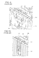
- FIG. 9 is a partial perspective view of a general electric connection box.
- Fig. 10 is a cross-sectional view taken along the line V-V shown in Fig. 9 .
- a general electric connection box 101 includes a box main body made of synthetic resin, which box main body structures an outer shell of the electric connection box; a cassette block 106 made of synthetic resin, in which a plurality of electric components, such relays and fuses, are mounted and which cassette block 106 is arranged in the box main body 102; and a side cover 107.
- the box main body 102 is formed into a box shape by a plurality of outer walls.
- the box main body 102 includes a groove 104 recessed from the outer wall and extending straight.
- the groove 104 receives electric wires joined with the electric components and connected with a electric power source such as a battery.
- the side cover 107 is slid along a lengthwise direction of the groove 104 and mounted at the box main body 102. When the side cover 107 is mounted at the box main body 102, the side cover 107 covers the groove 104 (see Patent document 1).
- Patent Document 1 Japan Patent Publication Application No. 2010-414808
- the engine room at which the general electric connection box 101 is mounted may washed by spraying pressured water of 8-12 Mpa (high pressure water washing) .
- pressured water of 8-12 Mpa (high pressure water washing)
- the pressured water may flow along the lengthwise direction of the groove 104 and penetrates through a gap formed straight between the groove 104 and the side cover 107 into the box main body 102.
- an object of the present invention is to provide an electric connection box which can have waterproof performance even if a car is washed by high pressured water.
- the present invention is to provide an electric connection box including a box main body having a groove recessed at an outer wall and extending straight, a side cover sliding along a lengthwise direction of the groove so as to be mounded at the box main body and covering the groove when the side cover is mounted at the box main body, and the side cover is provided with a plate member formed within a same geometric plane of the outer wall, and the plate member is provided with a flap projecting from the plate member along a widthwise direction of the groove.
- the side cover further includes a pair of parallel members projecting along the widthwise direction of the groove so as to be arranged at an interval to each other, and a connecting member connecting the pair of parallel members; and an insertion wall penetrating between the pair of parallel members so as to be positioned at a position corresponding to the connecting member.
- the box main body further includes a projection projecting toward the outside of the box main body from the insertion wall, and the projection is arranged at a position corresponding to an edge face of one of the pair of parallel members, which one is positioned at a more outer side than the other one.
- the electric connection box includes the box main body having the groove recessed at the outer wall and extending straight, the side cover sliding along the lengthwise direction of the groove so as to be mounded at the box main body and covering the groove when the side cover is mounted at the box main body, and the side cover is provided with the plate member formed within the same geometric plane of the outer wall, and the plate member is provided with the flap projecting from the plate member along the widthwise direction of the groove, so that when the car is washed by the high pressured water, the flap obstructs liquid like water flowing up along the lengthwise direction of the groove through the gap between the side cover and the groove and prevents that the water penetrates into the box main body. Therefore, the electric connection box having waterproof performance when the car is washed by high pressured water can be provided.
- the side cover further includes the pair of parallel members projecting along the widthwise direction of the groove so as to be arranged at the interval to each other, and the connecting member connecting the pair of parallel members; and the insertion wall penetrating between the pair of parallel members so as to be positioned at the position corresponding to the connecting member, so that when the car is washed by the high pressured water, the pressured water may firstly hit (strikes) the insertion wall, and energy of the water is decreased by striking the insertion wall; and the water after that strikes the connecting member and energy of the water is decreased by striking the connecting member; and the water after that strikes the other one of the pair of parallel members which is positioned at a more inner side than the one of the pair of parallel members, and energy of the water is decreased by striking the other one.
- energy of the water is decreased (eliminated) and it is prevented that the water penetrates into the box main body, so that the waterproof performance can be more improved.
- the box main body further includes a projection projecting toward the outside of the box main body from the insertion wall, and the projection is arranged at a position corresponding to an edge face of one of the pair of parallel members, which one is positioned at an outer side more than the other one, so that the projection covers the gap between the penetration wall and the one of the pair of parallel members.
- the electric connection box 1 shown in Fig. 1 is arranged in an engine room of a car for supplying electric power to various apparatuses mounted at the car.
- a junction box, a fuse block and a relay box are called by the electric connection box as a generic name, hereafter.
- the electric connection box 1 as shown in Fig. 1 includes a box main body 2 made of synthetic resin and structuring a shell of the electric connection box 1, a cassette block 6 in which a plurality of electric components such as a relay and a fuse is provided, and being made of synthetic resin and being mounted in the box main body 2, and a side cover 7.
- the box main body 2 includes a main body 3 formed into a frame shape by a plurality of outer walls 30, 31, an upper cover (not shown) formed into a pipe shape with a bottom plate and mounted at the main body 3 so as to cover an top surface 2a of the main body 3 for covering the electric components, and a lower cover 5 formed into a pipe shape with a bottom plate and being mounted at a bottom surface (side farther from the top surface 2a) of the main body 3.
- the electric connection box 1 shown in Fig. 1 is in a condition that the upper cover is removed.
- the main body 3 is formed with insulation synthetic resin by injection molding.
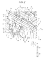
- the main body 3 includes a plurality of outer walls 30, 31, groove 4 arranged at the outer wall 31, and a pair of lock receiving members 39 to be locked respectively with a pair of later-described lock members 75 of the side cover 7, as shown in Figs. 1 , 2 .
- An arrow Y shown in Fig. 1 indicates a direction, in which the cover 5 approaches toward the main body 3, and a lengthwise direction of the groove 4 and the side cover 7.
- An arrow X indicates a widthwise direction of the groove 4 and the side cover 7.
- An arrow Z indicates a depth direction of the groove 4.
- the outer wall 31 includes a base wall 32, a middle wall 33 overlapped on an inside of the base wall 32, and an inner wall 34 overlapped on an inside of the middle wall 33 as shown in Figs. 1 , 2 .
- the end face, at an upper side in a direction by arrow Y, of the middle wall 33 projects from the base wall 32 (that is, exposed) .
- the end face, at the upper side in the direction by arrow Y, of the inner wall 34 projects from the middle wall 33 (that is, exposed).
- the upper cover is overlapped on the end face (exposed portion), at the upper side in the direction by arrow Y, of the middle wall 33 .
- a step portion is formed by a plurality of walls 32, 33 and 34.
- the base wall 32 includes an insertion wall 36, which is arranged at the side cover 7, penetrating between a pair of later-described deep-side parallel plate 78 and the second plate member 88 arranged at the both side edges, closer to the groove 4, of the base wall 32; and a first and second projections 37, 38 arranged at the insertion wall 36.
- the first and second projections 37, 38 are arranged at the pair of insertion walls 36.
- the projections 37, 38 are formed so as to project from an outer surface of the insertion wall 36. In other words, the projections 37, 38 are formed projecting outwardly.
- the first and second projections 37, 38 are arranged at a position corresponding to an end surface of the later-described second plate member 88 so as to be close to the second plate member 88 provided at the side cover 7.
- the first projection 37 is arranged only at one insertion wall 36 of the pair of insertion walls 36.
- the first projection 37 is formed along a lengthwise direction (direction by arrow Y) of the groove 4.
- the pair of second projections 38 is arranged so as to position the pair of later-described second plate members 88 of the side cover 7 between the pair of second projections 38.
- Each of the second projections 38 is formed along a widthwise direction (direction by arrow X) of the groove 4 .
- One second projection 38 of the pair of second projections 38 is continued to an end edge, at the upper side in the direction by arrow Y, of the first projection 37.
- the above first projection 37 and the second projections 38 correspond to "projection" in claims.
- the groove 4 is recessed from an outer surface of the outer wall 31, that is the plurality of walls 32, 33, 34, so as to be formed into u-shape by a bottom wall 4a arranged in parallel to the walls 32, 33, 34 at a deeper side than the wall 32, 33, 34, and a pair of side walls 4b extending vertically from the bottom wall 4a to connect the bottom wall 4a and the walls 32, 33, 34.
- the groove 4 extends straight along a direction from the top surface 2a toward the bottom surface (direction by arrow Y). Electric wires joined with a plurality of electric components, such a fuse and a relay, and connected to an electric power source, such a battery, are received in the groove 4.
- the side wall 4b includes a first wall 43 extending vertically from the insertion wall 36 (base wall 32) toward a deeper side; a second wall 45 arranged in parallel to the first wall 43 at a more inner side than the first wall 43; a connecting wall 42, parallel to the insertion wall 36, connecting the walls 43 and 45; and a vertical wall 35 (shown in Fig. 2 ) extending vertically from an edge, close to the groove 4, of the inner wall 34 toward the deeper side.
- the connecting wall 42 is arranged at an interval from the insertion wall 36. Between the walls 36 and 42, the deeper-side parallel plate member 78 as the other of later-described parallel portions of the side cover 7 penetrates.
- the pair of lock receiving members 39 is arranged so as to position the groove 4 therebetween along the direction by arrow X.
- the pair of lock receiving members 39 is arranged in a central area of the main body 3 in the direction by arrow Y.
- the cassette block 6 is formed as a whole into a block shape and each electric component is mounted therein.
- the cassette block is received in the main body 3 so as to direct the electric components, such as the mounted relay and fuse, to be located at the upper side in the direction by arrow Y of the main body 3.
- the other end of the electric wire is led through the side cover 7 to the outside of the box main body 2.
- the side cove 7 is continued between the inside and the outside of the box main body 2.
- the side cover 7 is formed, into a rectangular shape in plan view similar as a shape in plan view of the groove 4.
- the side cover 7 covers the groove 4 so as to be continued to the walls 32, 33, 34 within the same geometric plane of the outer surfaces of the walls 32, 33, 34.
- the side cover 7 is made of insulation synthetic resin by known injection molding.
- the side cover 7 includes a first member 7A and a second member 7B assembled on the first member 7A so as to be overlapped on the inner surface of the groove 4 (inner surfaces of the walls 4a, 4b).
- the side cover 7 is designed to be separable to the first member 7A and the second member 7B, and to be buildable thereby.
- the first member 7A includes integrally a first insert protect member 70 and a first wire passing section 73.
- the first insert protect member 70 includes a first plate 80 arranged at a position corresponding to the bottom wall 4a of the groove 4, a pair of first side plates 74 continued to the first plate 80 and arranged at a position corresponding to the side walls 4b of the groove 4, and the pair of lock members 75 locking with each of the lock receiving members 39 of the main body 3.
- the first plate 80 includes first-fifth plate members 81, 82, 83, 87, 88 .
- the first plate 80 is formed to have a length along the lengthwise direction (direction by arrow Y) longer than a length of a later-described second plate portion 91 of the second member 7B. When the second member 7B is assembled with the first member 7A, the first plate 80 projects from the later-described second plate portion 91 of the second member 7B, as shown in Fig. 2 .
- the first plate member 87 is positioned between the pair of lock receiving members 39 of the main body 3.
- a pair of second plate members 88 is arranged in parallel to the first plate member 87 so as to place the first plate member 87 therebetween (in the direction by arrow X) .
- An outer surface of the second plate member 88 is located at a deeper side than the first plate member 87 and also than the projections 37, 38.
- the second plate member 88 corresponds to "one of parallel members" described in claims.
- the pair of second plate members 88 includes a pair of hock members 89 projecting from an end portion, at the upper side in the direction by arrow Y, of the second plate member 88 so as to approach each other (in the direction by arrow X) .
- the hock members 89 are overlapped on a surface, at the upper side in the direction by arrow Y, of the first plate member 87.
- the third plate member 81 is continued to the end, at the upper side in the direction by arrow Y, of the first plate member 87 so as to be within the same geometric plane of the base wall 32.
- the third plate member 81 includes a pair of flaps 84 arranged at an end at the upper side in the direction by arrow Y of the third plate member 81 and projecting from the third plate member 81 along the widthwise direction of the groove 4 (direction by arrow X). That is, the pair of flaps 84 extends along the widthwise direction (direction by arrow X) so as to be separated to each other.
- the third plate member 81 is provided with the flaps 84 projecting from the third plate member 81 along the widthwise direction thereof (direction by arrow X) , so that a length of the side cover 7, in which the flaps 84 are arranged, along the widthwise direction (direction by arrow X) is larger (longer) than that of the third plate member 81, in which the flaps are not arranged.
- the third plate member 81 corresponds to "plate member" described in claims.
- the fourth plate member 82 is continued to an area, at the upper side in the direction by arrow Y, of the third plate member 81 so as to be within the same geometric plane of the middle wall 33.
- the fourth plate piece 82 includes a pair of flaps 85 projecting gradually according to nearing to an end, at the upper side in the direction by arrow Y, of the fourth plate member 82 from the fourth plate member 82 along the widthwise direction of the groove 4 (direction by arrow X) .
- the pair of flaps 85 extends along the widthwise direction of the groove 4 (direction by arrow X) so as to separate from each other.
- the fourth plate member 82 includes the flaps 85 projecting from the fourth plate member 82 along the widthwise direction (the direction by arrow X), so that length of the side cover 7, which the flaps 85 are provided, along the widthwise direction (direction by arrow X) is formed larger (longer) than that of the fourth plate member 82, which the flaps 85 are not provided.
- the fourth plate member 82 corresponds to "plate member" in claims.
- the fifth plate member 83 is continued to the fourth plate member 82 at the upper side in the direction by arrow Y within the same geometric plane of the inner wall 34.
- each one of the pair of first side plates 74 includes a first standing member 77; a deep-side parallel plate 78 continued to the first standing member 77 in parallel to the first-fifth plate members 87, 88, 81, 82, 83; a second standing member 79 (shown in Fig.
- the pair of first standing members 77 stands from the both ends of the first plate member 87 of the first plate 80 along the widthwise direction (direction by arrow X) toward the deep side so as to separate from each other.
- Each of the first standing members 77 corresponds to "connecting member” described in claims, to connect a later-described deep-side parallel plate 78 and the second plate member 88.
- the pair of first standing members 77 is arranged in parallel to the wall 43 and 45 from the first plate member 87 toward the third plate member 81 (along the direction by arrow Y)
- the insertion wall 36 penetrates between the deep-side parallel plate 78 and the second plate member 88.
- a top end of the deep-side parallel plate 78 penetrates between the above-mentionedwalls 36 and the connecting wall 42.
- the deep-side parallel plate 78 and the second plate member 88 extend (project) along the widthwise direction of the groove 4 (direction by arrow X) in parallel to each other.
- the deep-side parallel plate 78 and the second plate member 88 are also arranged in parallel to the flaps 84 and 85 (third and fourth plate members 81, 82).
- each one of the pair of third standing members 76 includes an upper standing portion 76a and a lower standing portion 76b positioned under the upper standing portion 76a.
- the standing portions 76a, 76b are arranged at an interval to each other along the lengthwise direction (direction by arrow Y) and the second standing member 79 is positioned between the standing portions.
- the lock member 72 is provided on each surface of the pair of upper standing portions 76a, which surfaces are opposite to each.
- each of the pair of lock members 75 is provided between an end face, closer to the second plate member 88, of the first plate member 87 and the second plate member 88.
- the first wire passing section 73 is formed into a gutter shape extending straight along the lengthwise direction (direction by arrow Y).
- the second member 7B includes integrally a second penetration protect member 90 and a second wire passing section 93 continued to a bottom surface of the second penetration protect member 90.
- the second penetration protect member 90 is arranged corresponding to the first plate 80 of the first member 7A.
- the second penetration protect member 90 includes a second plate portion 91 overlapped on the bottom wall 4a of the groove 4; a pair of second side plates 92 overlapped respectively on each of the side walls 4b of the groove 4; and a pair of lock receiving members 94 provided respectively at each of the pair of second side plates 92, and locked respectively with each of lock members 72 of the first member 7A.
- the pair of second side plates 92 penetrates between the third standing members 76 and the second standing member 79 of the first member 7A.
- the lock receiving member 94 is locked with the lock member 72 of the first member 7A.
- the second wire passing section 93 is formed into a gutter shape.
- the wire passing sections 73, 79 form a cylindrical shape.
- the electric wire, which is connected with electric components, is passed through the wire passing sections 73, 93.
- Fixing material such as adhesive tape is wound around the electric wires, which are connected with electric components, in the wire passing sections 73, 93 and filled in the wire passing sections 73, 93 so as to eliminate gaps therebetween.
- the first member 7A and second member 7B are closed to each other.
- the lock member 72 of the first member 7A is locked with the lock receiving member 94, so that the first member 7A and the second member 7B are assembled to each other, and the side cover 7 is assembled.
- the electric wire which one end thereof is connected with each of the electric components and the other thereof is led out from the main body 3 (box main body 2), is passed through the side cover 7.
- the assembled main body 3 which the electric wire is passed through the side cover 7 is closed so as to make the second plate 91 of the second member 7B correspond to the bottom wall 4a of the groove 4, and each of the second side plates 92 is closed to each of the pair of side walls 4b.
- the side cover 7 is slid along the lengthwise direction of the groove 4 (direction by arrow Y). Thereby, the lock member 75 is locked with the lock receiving member 39 of the main body 3, and the side cover 7 is mounted at the main body 3 (box main body 2) so as to cover the groove 4.
- the base wall 32 and the third plate member 81 are arranged to be continued within the same geometric plane
- the middle wall 33 and the fourth plate member 82 are arranged to be continued within the same geometric plane.
- the insertion wall 36 arranged at the main body 3 penetrates between the deep-side parallel plate 78 and the second plate member 88 arranged at the side cover 7.
- the projections 37, 38 arranged at the main body 3 are positioned so as to correspond to the end face of the second plate member 88. Thereafter, in condition that the electric wire is passed through the side cover 7, the adhesive tape 8 as the fixing member is wound around the electric wire and filled in the wire passing sections 73, 93 so as to eliminate any gaps. Then, the lower cover 5 is mounted at the main boy 3 so as to cover the bottom face of the main body 3. Thereby, the box main body 2 is assembled and the side cover 7 is mounted at the box main body 2. Thus, the electric connection box 1 is completed.
- the electric connection box 1 includes the box main body 2 having the groove 4 recessed from the outer wall 31 so as to extend straight; and the side cover 7 slid along the lengthwise direction (direction by arrow Y) of the groove 4 so as to be mounted at the box main body 2 and coving the groove 4 when the side cover is mounted at the box main body 2.
- the side cover 7 is provided with the third and fourth plate members 81, 82 to be arranged within the same geometrical plane of the outer wall 31.
- Each of the first and fourth plate members 81, 82 is provided with the flap 84, 85 projecting from the third and fourth plate member 81, 82 along the widthwise direction (direction by arrow X) of the groove 4.
- the flaps 84, 85 obstruct liquid such as water flowing up between the side cover 7 and the groove 4 along the lengthwise direction (direction by arrow Y). Thus, it is prevented that the water penetrates into the box main body 2.
- the electric connection box 1 can maintain waterproof.
- the side cover 7 includes the deep-side parallel plate 78 and the second plate member 88 projecting along the widthwise direction (direction by arrow X) of the groove 4 and arranged at the interval to each other as the pair of parallel member, and the first standing member 77 as the connecting member connecting the pair of plate members 78, 88.
- the outer wall 31 is provided with the insertion wall 36 penetrating between the deep-side parallel plate 78 and the second plate member 88 and positioned so as to correspond to the first standing member 77.
- the water which energy is decreased, swashes the first standing member 77, and the energy of the water is further decreased. After that, the water hits the deep-side parallel plate 78 as the other parallel member arranged at inner side, and the energy of the water is further decreased.
- the energy of the water can be decreased (absorbed), so that it can be prevented that the water penetrates into the box main body 2. Therefore, waterproof can be more improved.
- the box main body 2 includes projections 37, 38 projecting from the insertion wall 36 toward outside of the box main body 2.
- the projections 37, 38 are arranged to correspond to the end face of the second plate member 88 as the one parallel member of the deep-side parallel plate 78 and the second plate member 88 positioned outer side more than the other one.
- the projections 37, 38 cover the gap between the insertion wall 36 and the second plate member 88, and it can be prevented that the water penetrates into the box main body 2. Therefore, waterproof can be more improved.
- the plurality of flaps 84, 85 the plurality of flaps 84, 85.
- the present invention is limited on this case, one of the plurality of flaps 84, 85 may be provided.
- the plurality of projections 37, 38 are limited on this case, one of the plurality of projections 37, 38 may be provided.
Landscapes
- Engineering & Computer Science (AREA)
- Mechanical Engineering (AREA)
- Microelectronics & Electronic Packaging (AREA)
- Connection Or Junction Boxes (AREA)
- Casings For Electric Apparatus (AREA)
- Connector Housings Or Holding Contact Members (AREA)
Abstract
Description
- The priority application Number Japan Patent Application
2010-173484 - This invention relates to an electric connection box to be mounted at an engine room of a car.
- In a vehicle as a mobile body, various electronic apparatuses are generally mounted. For supplying electric power to the various electronic apparatuses, an electric connection box structured integrally with electric components such a connector, a relay, a fuse and the like is provided suitably at a suitable position between the electronic apparatuses and an electric power source in the vehicle.
- The electric connection box can be named a junction box, a fuse block, or a relay box. The junction box, the fuse block and the relay box are called by the electric connection box as a generic name, hereafter.
-
Fig. 9 is a partial perspective view of a general electric connection box.Fig. 10 is a cross-sectional view taken along the line V-V shown inFig. 9 . A generalelectric connection box 101 includes a box main body made of synthetic resin, which box main body structures an outer shell of the electric connection box; acassette block 106 made of synthetic resin, in which a plurality of electric components, such relays and fuses, are mounted and whichcassette block 106 is arranged in the boxmain body 102; and aside cover 107. - The box
main body 102 is formed into a box shape by a plurality of outer walls. The boxmain body 102 includes agroove 104 recessed from the outer wall and extending straight. Thegroove 104 receives electric wires joined with the electric components and connected with a electric power source such as a battery. - The
side cover 107 is slid along a lengthwise direction of thegroove 104 and mounted at the boxmain body 102. When theside cover 107 is mounted at the boxmain body 102, theside cover 107 covers the groove 104 (see Patent document 1). - Patent Document 1 : Japan Patent Publication Application No.
2010-414808 - The engine room at which the general
electric connection box 101 is mounted, may washed by spraying pressured water of 8-12 Mpa (high pressure water washing) . When theelectric connection box 101 is washed by high pressured water, the pressured water may flow along the lengthwise direction of thegroove 104 and penetrates through a gap formed straight between thegroove 104 and the side cover 107 into the boxmain body 102. - For solving the above problem, an object of the present invention is to provide an electric connection box which can have waterproof performance even if a car is washed by high pressured water.
- In order to overcome the above problems and attain the object, the present invention is to provide an electric connection box including a box main body having a groove recessed at an outer wall and extending straight, a side cover sliding along a lengthwise direction of the groove so as to be mounded at the box main body and covering the groove when the side cover is mounted at the box main body, and the side cover is provided with a plate member formed within a same geometric plane of the outer wall, and the plate member is provided with a flap projecting from the plate member along a widthwise direction of the groove.
- According to the present invention, the side cover further includes a pair of parallel members projecting along the widthwise direction of the groove so as to be arranged at an interval to each other, and a connecting member connecting the pair of parallel members; and an insertion wall penetrating between the pair of parallel members so as to be positioned at a position corresponding to the connecting member.
- According to the present invention, the box main body further includes a projection projecting toward the outside of the box main body from the insertion wall, and the projection is arranged at a position corresponding to an edge face of one of the pair of parallel members, which one is positioned at a more outer side than the other one.
- According to the present invention, the electric connection box includes the box main body having the groove recessed at the outer wall and extending straight, the side cover sliding along the lengthwise direction of the groove so as to be mounded at the box main body and covering the groove when the side cover is mounted at the box main body, and the side cover is provided with the plate member formed within the same geometric plane of the outer wall, and the plate member is provided with the flap projecting from the plate member along the widthwise direction of the groove, so that when the car is washed by the high pressured water, the flap obstructs liquid like water flowing up along the lengthwise direction of the groove through the gap between the side cover and the groove and prevents that the water penetrates into the box main body. Therefore, the electric connection box having waterproof performance when the car is washed by high pressured water can be provided.
- According to the present invention, the side cover further includes the pair of parallel members projecting along the widthwise direction of the groove so as to be arranged at the interval to each other, and the connecting member connecting the pair of parallel members; and the insertion wall penetrating between the pair of parallel members so as to be positioned at the position corresponding to the connecting member, so that when the car is washed by the high pressured water, the pressured water may firstly hit (strikes) the insertion wall, and energy of the water is decreased by striking the insertion wall; and the water after that strikes the connecting member and energy of the water is decreased by striking the connecting member; and the water after that strikes the other one of the pair of parallel members which is positioned at a more inner side than the one of the pair of parallel members, and energy of the water is decreased by striking the other one. Thus, energy of the water is decreased (eliminated) and it is prevented that the water penetrates into the box main body, so that the waterproof performance can be more improved.
- According to the present invention, the box main body further includes a projection projecting toward the outside of the box main body from the insertion wall, and the projection is arranged at a position corresponding to an edge face of one of the pair of parallel members, which one is positioned at an outer side more than the other one, so that the projection covers the gap between the penetration wall and the one of the pair of parallel members. Thereby, it can be prevented that liquid like water penetrates into the box main body, so that the waterproof performance can be further more improved.
-
-
Fig. 1 is a perspective view of an electric connection box of an embodiment according to the present invention; -
Fig. 2 is a partial perspective view of the electric connection box shown inFig. 1 ; -
Fig. 3 is a perspective view showing a cross-section taken along the line III-III shown inFig. 2 ; -
Fig. 4 is a perspective view showing expanded important area shown inFig. 3 ; -
Fig. 5 is a perspective view of a side cover structuring the electric connection box shown inFig. 1 ; -
Fig. 6 is a perspective view showing a cross-section taken along the line VI-VI shown inFig. 2 ; -
Fig. 7 is a perspective view showing a cross-section taken along the line VII-VII shown inFig. 2 ; -
Fig. 8 is a perspective view showing a cross-section taken along the line VIII-VIII shown inFig. 7 ; -
Fig. 9 is a perspective view showing a partial area of a general electric connection box; and -
Fig. 10 is a perspective view showing a cross-section taken along the line X-X shown inFig. 9 . - An electric connection box as an embodiment according to the present invention is described with reference to drawings
Figs. 1-8 . Theelectric connection box 1 shown inFig. 1 is arranged in an engine room of a car for supplying electric power to various apparatuses mounted at the car. In the specification, a junction box, a fuse block and a relay box are called by the electric connection box as a generic name, hereafter. - The
electric connection box 1 as shown inFig. 1 includes a boxmain body 2 made of synthetic resin and structuring a shell of theelectric connection box 1, acassette block 6 in which a plurality of electric components such as a relay and a fuse is provided, and being made of synthetic resin and being mounted in the boxmain body 2, and aside cover 7. - The box
main body 2 includes amain body 3 formed into a frame shape by a plurality ofouter walls main body 3 so as to cover antop surface 2a of themain body 3 for covering the electric components, and alower cover 5 formed into a pipe shape with a bottom plate and being mounted at a bottom surface (side farther from thetop surface 2a) of themain body 3. Theelectric connection box 1 shown inFig. 1 is in a condition that the upper cover is removed. - The
main body 3 is formed with insulation synthetic resin by injection molding. Themain body 3 includes a plurality ofouter walls groove 4 arranged at theouter wall 31, and a pair oflock receiving members 39 to be locked respectively with a pair of later-describedlock members 75 of theside cover 7, as shown inFigs. 1 ,2 . An arrow Y shown inFig. 1 indicates a direction, in which thecover 5 approaches toward themain body 3, and a lengthwise direction of thegroove 4 and theside cover 7. An arrow X indicates a widthwise direction of thegroove 4 and theside cover 7. An arrow Z indicates a depth direction of thegroove 4. - The
outer wall 31 includes abase wall 32, amiddle wall 33 overlapped on an inside of thebase wall 32, and aninner wall 34 overlapped on an inside of themiddle wall 33 as shown inFigs. 1 ,2 . As shown inFig. 2 , the end face, at an upper side in a direction by arrow Y, of themiddle wall 33 projects from the base wall 32 (that is, exposed) . The end face, at the upper side in the direction by arrow Y, of theinner wall 34 projects from the middle wall 33 (that is, exposed). The upper cover is overlapped on the end face (exposed portion), at the upper side in the direction by arrow Y, of themiddle wall 33 . Thus, at theouter wall 31, a step portion is formed by a plurality ofwalls - As shown in
Figs. 2 ,3 , thebase wall 32 includes aninsertion wall 36, which is arranged at theside cover 7, penetrating between a pair of later-described deep-sideparallel plate 78 and thesecond plate member 88 arranged at the both side edges, closer to thegroove 4, of thebase wall 32; and a first andsecond projections insertion wall 36. - As shown in
Figs. 2 ,3 , the first andsecond projections insertion walls 36. Theprojections insertion wall 36. In other words, theprojections second projections second plate member 88 so as to be close to thesecond plate member 88 provided at theside cover 7. Thefirst projection 37 is arranged only at oneinsertion wall 36 of the pair ofinsertion walls 36. Thefirst projection 37 is formed along a lengthwise direction (direction by arrow Y) of thegroove 4. The pair ofsecond projections 38 is arranged so as to position the pair of later-describedsecond plate members 88 of theside cover 7 between the pair ofsecond projections 38. Each of thesecond projections 38 is formed along a widthwise direction (direction by arrow X) of thegroove 4 . Onesecond projection 38 of the pair ofsecond projections 38 is continued to an end edge, at the upper side in the direction by arrow Y, of thefirst projection 37. The abovefirst projection 37 and thesecond projections 38 correspond to "projection" in claims. - As shown in
Figs. 2 ,3 , thegroove 4 is recessed from an outer surface of theouter wall 31, that is the plurality ofwalls bottom wall 4a arranged in parallel to thewalls wall side walls 4b extending vertically from thebottom wall 4a to connect thebottom wall 4a and thewalls groove 4 extends straight along a direction from thetop surface 2a toward the bottom surface (direction by arrow Y). Electric wires joined with a plurality of electric components, such a fuse and a relay, and connected to an electric power source, such a battery, are received in thegroove 4. - As shown in
Figs. 3, 4 , theside wall 4b includes afirst wall 43 extending vertically from the insertion wall 36 (base wall 32) toward a deeper side; asecond wall 45 arranged in parallel to thefirst wall 43 at a more inner side than thefirst wall 43; a connectingwall 42, parallel to theinsertion wall 36, connecting thewalls Fig. 2 ) extending vertically from an edge, close to thegroove 4, of theinner wall 34 toward the deeper side. - The connecting
wall 42 is arranged at an interval from theinsertion wall 36. Between thewalls parallel plate member 78 as the other of later-described parallel portions of theside cover 7 penetrates. - The pair of
lock receiving members 39 is arranged so as to position thegroove 4 therebetween along the direction by arrow X. The pair oflock receiving members 39 is arranged in a central area of themain body 3 in the direction by arrow Y. - As shown in
Fig. 2 , thecassette block 6 is formed as a whole into a block shape and each electric component is mounted therein. The cassette block is received in themain body 3 so as to direct the electric components, such as the mounted relay and fuse, to be located at the upper side in the direction by arrow Y of themain body 3. - The other end of the electric wire, one end of which is connected with each one of the various electric components, is led through the
side cover 7 to the outside of the boxmain body 2. Theside cove 7 is continued between the inside and the outside of the boxmain body 2. Theside cover 7 is formed, into a rectangular shape in plan view similar as a shape in plan view of thegroove 4. When theside cover 7 is mounted at the boxmain body 2, theside cover 7 covers thegroove 4 so as to be continued to thewalls walls - The
side cover 7 is made of insulation synthetic resin by known injection molding. Theside cover 7 includes afirst member 7A and asecond member 7B assembled on thefirst member 7A so as to be overlapped on the inner surface of the groove 4 (inner surfaces of thewalls side cover 7 is designed to be separable to thefirst member 7A and thesecond member 7B, and to be buildable thereby. - As shown in
Fig. 5 , thefirst member 7A includes integrally a first insert protectmember 70 and a firstwire passing section 73. - The first insert protect
member 70, as shown inFig. 5 , includes afirst plate 80 arranged at a position corresponding to thebottom wall 4a of thegroove 4, a pair offirst side plates 74 continued to thefirst plate 80 and arranged at a position corresponding to theside walls 4b of thegroove 4, and the pair oflock members 75 locking with each of thelock receiving members 39 of themain body 3.
Thefirst plate 80, as shown inFig. 2 , includes first-fifth plate members first plate 80 is formed to have a length along the lengthwise direction (direction by arrow Y) longer than a length of a later-describedsecond plate portion 91 of thesecond member 7B. When thesecond member 7B is assembled with thefirst member 7A, thefirst plate 80 projects from the later-describedsecond plate portion 91 of thesecond member 7B, as shown inFig. 2 . - When the
side cover 7 is mounted at the main body 3 (box main body 2), thefirst plate member 87 is positioned between the pair oflock receiving members 39 of themain body 3. - As shown in
Figs. 3, 4 , a pair ofsecond plate members 88 is arranged in parallel to thefirst plate member 87 so as to place thefirst plate member 87 therebetween (in the direction by arrow X) . An outer surface of thesecond plate member 88 is located at a deeper side than thefirst plate member 87 and also than theprojections second plate member 88 corresponds to "one of parallel members" described in claims. - As shown in
Figs . 7, 8 , the pair ofsecond plate members 88 includes a pair ofhock members 89 projecting from an end portion, at the upper side in the direction by arrow Y, of thesecond plate member 88 so as to approach each other (in the direction by arrow X) . Thehock members 89 are overlapped on a surface, at the upper side in the direction by arrow Y, of thefirst plate member 87. - As shown in
Fig. 7 , thethird plate member 81 is continued to the end, at the upper side in the direction by arrow Y, of thefirst plate member 87 so as to be within the same geometric plane of thebase wall 32. Thethird plate member 81 includes a pair offlaps 84 arranged at an end at the upper side in the direction by arrow Y of thethird plate member 81 and projecting from thethird plate member 81 along the widthwise direction of the groove 4 (direction by arrow X). That is, the pair offlaps 84 extends along the widthwise direction (direction by arrow X) so as to be separated to each other. Thus, thethird plate member 81 is provided with theflaps 84 projecting from thethird plate member 81 along the widthwise direction thereof (direction by arrow X) , so that a length of theside cover 7, in which theflaps 84 are arranged, along the widthwise direction (direction by arrow X) is larger (longer) than that of thethird plate member 81, in which the flaps are not arranged. Thethird plate member 81 corresponds to "plate member" described in claims. - As shown in
Figs. 6 ,7 , thefourth plate member 82 is continued to an area, at the upper side in the direction by arrow Y, of thethird plate member 81 so as to be within the same geometric plane of themiddle wall 33. Thefourth plate piece 82 includes a pair offlaps 85 projecting gradually according to nearing to an end, at the upper side in the direction by arrow Y, of thefourth plate member 82 from thefourth plate member 82 along the widthwise direction of the groove 4 (direction by arrow X) . The pair offlaps 85 extends along the widthwise direction of the groove 4 (direction by arrow X) so as to separate from each other. Thus, thefourth plate member 82 includes theflaps 85 projecting from thefourth plate member 82 along the widthwise direction (the direction by arrow X), so that length of theside cover 7, which theflaps 85 are provided, along the widthwise direction (direction by arrow X) is formed larger (longer) than that of thefourth plate member 82, which theflaps 85 are not provided. Thefourth plate member 82 corresponds to "plate member" in claims. - The
fifth plate member 83 is continued to thefourth plate member 82 at the upper side in the direction by arrow Y within the same geometric plane of theinner wall 34. - As shown in
Figs. 5 and8 , each one of the pair offirst side plates 74 includes a first standingmember 77; a deep-sideparallel plate 78 continued to the first standingmember 77 in parallel to the first-fifth plate members Fig. 4 ) standing from the deep-sideparallel plate 78 toward a deep side in parallel to the first standingmember 77; a third standingmember 76 standing from the deep-sideparallel plate 78 toward the deep side at an inner side than thesecond standing plate 79; a pair of fourth standingmembers 71 standing from both edges of thefifth plate member 83 along the widthwise direction (direction by arrow X) to be overlapped on eachvertical wall 35 of themain body 3; and a pair oflock members 72 engaged with each of later-describedlock receiving members 94 of thesecond member 7B. - The pair of first standing
members 77, as shown inFig. 4 , stands from the both ends of thefirst plate member 87 of thefirst plate 80 along the widthwise direction (direction by arrow X) toward the deep side so as to separate from each other. Each of the first standingmembers 77 corresponds to "connecting member" described in claims, to connect a later-described deep-sideparallel plate 78 and thesecond plate member 88. When theinsertion wall 36 penetrates between the later-describedparallel plate 78 and thesecond plate member 88, each of the first standingmembers 77 is positioned corresponding to theinsertion wall 36. The pair of first standingmembers 77 is arranged in parallel to thewall first plate member 87 toward the third plate member 81 (along the direction by arrow Y) - As shown in
Figs. 3, 4 , theinsertion wall 36 penetrates between the deep-sideparallel plate 78 and thesecond plate member 88. A top end of the deep-sideparallel plate 78 penetrates between the above-mentionedwalls 36 and the connectingwall 42. The deep-sideparallel plate 78 and thesecond plate member 88 extend (project) along the widthwise direction of the groove 4 (direction by arrow X) in parallel to each other. The deep-sideparallel plate 78 and thesecond plate member 88 are also arranged in parallel to theflaps 84 and 85 (third andfourth plate members 81, 82). - As shown in
Fig. 6 , the pair of third standingmembers 76 is arranged in parallel to the first and second standingmembers Fig. 6 , when thesecond member 7B is assembled to thefirst member 7A, a later-describedsecond side plate 92 of thesecond member 7B penetrates between thethird standing members 76 and the second standingmember 79. As shown inFigs. 5 ,6 , each one of the pair of third standingmembers 76 includes anupper standing portion 76a and alower standing portion 76b positioned under the upper standingportion 76a. The standingportions member 79 is positioned between the standing portions. Thelock member 72 is provided on each surface of the pair ofupper standing portions 76a, which surfaces are opposite to each. - As shown in
Fig. 2 , each of the pair oflock members 75 is provided between an end face, closer to thesecond plate member 88, of thefirst plate member 87 and thesecond plate member 88. - As shown in
Fig. 2 , the firstwire passing section 73 is formed into a gutter shape extending straight along the lengthwise direction (direction by arrow Y). - As shown in
Fig. 5 , thesecond member 7B includes integrally a second penetration protectmember 90 and a secondwire passing section 93 continued to a bottom surface of the second penetration protectmember 90. - As shown in
Figs. 5 ,6 , the second penetration protectmember 90 is arranged corresponding to thefirst plate 80 of thefirst member 7A. The second penetration protectmember 90 includes asecond plate portion 91 overlapped on thebottom wall 4a of thegroove 4; a pair ofsecond side plates 92 overlapped respectively on each of theside walls 4b of thegroove 4; and a pair oflock receiving members 94 provided respectively at each of the pair ofsecond side plates 92, and locked respectively with each oflock members 72 of thefirst member 7A. - When the
first member 7A is assembled with thesecond member 7B, the pair ofsecond side plates 92 penetrates between thethird standing members 76 and the second standingmember 79 of thefirst member 7A. When each of thesecond side plates 92 penetrates between thethird standing members 76 and the second standingmember 79, thelock receiving member 94 is locked with thelock member 72 of thefirst member 7A. - The second
wire passing section 93 is formed into a gutter shape. When thefirst member 7A is assembled with thesecond member 7B, thewire passing sections wire passing sections wire passing sections wire passing sections - Procedure of assembling the above
electric connection box 1 will be described. Each of electric components, to which one end of electric wire is connected, is mounted at thecassette block 6, and thecassette block 6, which each of electric components is mounted, is received in themain body 3. Instead of that, after placing thecassette block 6, which each of electric components is mounted, in themain body 3, the end of the electric wire may be connected with each of the electric components. In the case, thecassette block 6 is received in themain body 3 so as to locate the electric components such a relay and fuse at the side of theupper surface 2a of themain body 3. The other end of the electric wire, which one end is connected to the electric component, is led from the side ofupper surface 2a ofmain body 3, and arranged between thefirst member 7A and thesecond member 7B of theside cover 7. Thereafter, thefirst member 7A andsecond member 7B are closed to each other. Thereby, thelock member 72 of thefirst member 7A is locked with thelock receiving member 94, so that thefirst member 7A and thesecond member 7B are assembled to each other, and theside cover 7 is assembled. At the time, the electric wire which one end thereof is connected with each of the electric components and the other thereof is led out from the main body 3 (box main body 2), is passed through theside cover 7. Thereafter, the assembledmain body 3 which the electric wire is passed through theside cover 7, is closed so as to make thesecond plate 91 of thesecond member 7B correspond to thebottom wall 4a of thegroove 4, and each of thesecond side plates 92 is closed to each of the pair ofside walls 4b. Theside cover 7 is slid along the lengthwise direction of the groove 4 (direction by arrow Y). Thereby, thelock member 75 is locked with thelock receiving member 39 of themain body 3, and theside cover 7 is mounted at the main body 3 (box main body 2) so as to cover thegroove 4. When theside cover 7 is mounted at the main body 3 (box main body 2), thebase wall 32 and thethird plate member 81 are arranged to be continued within the same geometric plane, and themiddle wall 33 and thefourth plate member 82 are arranged to be continued within the same geometric plane. Theinsertion wall 36 arranged at themain body 3 penetrates between the deep-sideparallel plate 78 and thesecond plate member 88 arranged at theside cover 7. Theprojections main body 3 are positioned so as to correspond to the end face of thesecond plate member 88. Thereafter, in condition that the electric wire is passed through theside cover 7, the adhesive tape 8 as the fixing member is wound around the electric wire and filled in thewire passing sections lower cover 5 is mounted at themain boy 3 so as to cover the bottom face of themain body 3. Thereby, the boxmain body 2 is assembled and theside cover 7 is mounted at the boxmain body 2. Thus, theelectric connection box 1 is completed. - According to the above embodiment, the
electric connection box 1 includes the boxmain body 2 having thegroove 4 recessed from theouter wall 31 so as to extend straight; and theside cover 7 slid along the lengthwise direction (direction by arrow Y) of thegroove 4 so as to be mounted at the boxmain body 2 and coving thegroove 4 when the side cover is mounted at the boxmain body 2. Theside cover 7 is provided with the third andfourth plate members outer wall 31. Each of the first andfourth plate members flap fourth plate member groove 4. Thereby, when the car is washed by high-pressured water, theflaps side cover 7 and thegroove 4 along the lengthwise direction (direction by arrow Y). Thus, it is prevented that the water penetrates into the boxmain body 2. When the car is washed by high-pressure water, theelectric connection box 1 can maintain waterproof. - The
side cover 7 includes the deep-sideparallel plate 78 and thesecond plate member 88 projecting along the widthwise direction (direction by arrow X) of thegroove 4 and arranged at the interval to each other as the pair of parallel member, and the first standingmember 77 as the connecting member connecting the pair ofplate members outer wall 31 is provided with theinsertion wall 36 penetrating between the deep-sideparallel plate 78 and thesecond plate member 88 and positioned so as to correspond to the first standingmember 77. Thereby, when the car is washed by the high-pressure water, the pressured water firstly hits (swash) theinsertion wall 36, and the energy of the water is decreased. The water, which energy is decreased, swashes the first standingmember 77, and the energy of the water is further decreased. After that, the water hits the deep-sideparallel plate 78 as the other parallel member arranged at inner side, and the energy of the water is further decreased. Thus, the energy of the water can be decreased (absorbed), so that it can be prevented that the water penetrates into the boxmain body 2. Therefore, waterproof can be more improved. - The box
main body 2 includesprojections insertion wall 36 toward outside of the boxmain body 2. Theprojections second plate member 88 as the one parallel member of the deep-sideparallel plate 78 and thesecond plate member 88 positioned outer side more than the other one. Thereby, theprojections insertion wall 36 and thesecond plate member 88, and it can be prevented that the water penetrates into the boxmain body 2. Therefore, waterproof can be more improved. - According to the above embodiment, the plurality of
flaps flaps - According to the above embodiment, the plurality of
projections projections - The present inventions are described based in the embodiments as mentioned above, but the present invention is not limited in above embodiments. Various change and modifications can be made with the scope of the present invention.
-
- 1
- Electric connection box
- 2
- Box main body
- 7
- Side cover
- 31
- Outer wall
- 36
- Insertion wall
- 37
- First projection (projecting portion)
- 38
- Second projection (projecting portion)
- 77
- First standing member (connecting member)
- 78
- Deep-side parallel member (Other of parallel member)
- 81
- Third plate member (plate member)
- 82
- Fourth plate member (plate member)
- 84, 85
- Flap
- 88
- Second plate member (one of parallel member)
- Direction by arrow Y
- Lengthwise direction
- Direction by arrow X
- Widthwise direction
Claims (3)
- An electric connection box, comprising:a box main body having a groove recessed from an outer wall of the box main body, the groove extending straight; anda side cover slid along a lengthwise direction of the groove so as to be mounted at the box main body, and covering the groove when the side cover is mounted at the box main body,wherein the side cover is provided with a plate member to be formed so as to be arranged within a same geometrical plane of the outer wall,wherein the plate member is provided with a flap projecting from the plate member along a widthwise direction of the groove.
- The electric connection box according to claim 1, wherein the side cover comprises:A pair of parallel members projecting along the widthwise direction of the groove so as to be arranged at an interval to each other; anda connecting member connecting the pair of parallel members;wherein the outer wall is provided with an insertion wall penetrating between the pair of parallel members so as to be positioned at a position corresponding to the connecting member.
- The electric connection box according to claim 2, wherein the insertion wall comprises a projection projecting from the insertion wall toward an outside of the box main body, wherein the projection is arranged to correspond to an end face of one of the parallel members which one is located at outer side more than the other of the parallel members.
Applications Claiming Priority (1)
| Application Number | Priority Date | Filing Date | Title |
|---|---|---|---|
| JP2010173484A JP5619514B2 (en) | 2010-08-02 | 2010-08-02 | Electrical junction box |
Publications (3)
| Publication Number | Publication Date |
|---|---|
| EP2415642A2 true EP2415642A2 (en) | 2012-02-08 |
| EP2415642A3 EP2415642A3 (en) | 2014-02-19 |
| EP2415642B1 EP2415642B1 (en) | 2020-10-07 |
Family
ID=44906681
Family Applications (1)
| Application Number | Title | Priority Date | Filing Date |
|---|---|---|---|
| EP11176281.1A Active EP2415642B1 (en) | 2010-08-02 | 2011-08-02 | Electric connection box |
Country Status (5)
| Country | Link |
|---|---|
| US (1) | US9226423B2 (en) |
| EP (1) | EP2415642B1 (en) |
| JP (1) | JP5619514B2 (en) |
| CN (1) | CN102347595B (en) |
| ES (1) | ES2829248T3 (en) |
Families Citing this family (5)
| Publication number | Priority date | Publication date | Assignee | Title |
|---|---|---|---|---|
| JP5919081B2 (en) * | 2012-04-23 | 2016-05-18 | 矢崎総業株式会社 | Electrical junction box |
| JP6904995B2 (en) * | 2019-03-11 | 2021-07-21 | 矢崎総業株式会社 | Electrical junction box |
| JP6871292B2 (en) * | 2019-03-11 | 2021-05-12 | 矢崎総業株式会社 | Resin structure |
| JP2021111997A (en) * | 2020-01-07 | 2021-08-02 | 矢崎総業株式会社 | Electric connection box and wire harness |
| JP7469075B2 (en) * | 2020-03-04 | 2024-04-16 | 矢崎総業株式会社 | Resin Structure |
Citations (1)
| Publication number | Priority date | Publication date | Assignee | Title |
|---|---|---|---|---|
| JP2010041808A (en) | 2008-08-04 | 2010-02-18 | Sumitomo Wiring Syst Ltd | Electrical connection box |
Family Cites Families (9)
| Publication number | Priority date | Publication date | Assignee | Title |
|---|---|---|---|---|
| US5897392A (en) * | 1997-03-26 | 1999-04-27 | Yazaki Corporation | Wire retaining clip |
| JP4677286B2 (en) * | 2005-05-24 | 2011-04-27 | 矢崎総業株式会社 | Electrical junction box |
| EP1731373B1 (en) * | 2005-06-08 | 2008-05-28 | Yazaki Corporation | Wiring harness holding device |
| JP4878473B2 (en) * | 2005-11-22 | 2012-02-15 | 矢崎総業株式会社 | Terminal fitting and electric junction box provided with the terminal fitting |
| JP2007288975A (en) | 2006-04-19 | 2007-11-01 | Yazaki Corp | Electrical connection box |
| JP2007312494A (en) * | 2006-05-17 | 2007-11-29 | Yazaki Corp | Electric connection box |
| JP4605144B2 (en) * | 2006-11-06 | 2011-01-05 | 住友電装株式会社 | Electrical junction box |
| JP4989211B2 (en) * | 2006-12-21 | 2012-08-01 | 矢崎総業株式会社 | Electrical junction box |
| US7586038B2 (en) * | 2006-12-21 | 2009-09-08 | Yazaki Corporation | Electrical junction box and assembling method thereof |
-
2010
- 2010-08-02 JP JP2010173484A patent/JP5619514B2/en active Active
-
2011
- 2011-07-15 US US13/137,016 patent/US9226423B2/en active Active
- 2011-08-02 EP EP11176281.1A patent/EP2415642B1/en active Active
- 2011-08-02 ES ES11176281T patent/ES2829248T3/en active Active
- 2011-08-02 CN CN201110218943.8A patent/CN102347595B/en active Active
Patent Citations (1)
| Publication number | Priority date | Publication date | Assignee | Title |
|---|---|---|---|---|
| JP2010041808A (en) | 2008-08-04 | 2010-02-18 | Sumitomo Wiring Syst Ltd | Electrical connection box |
Also Published As
| Publication number | Publication date |
|---|---|
| US20120024559A1 (en) | 2012-02-02 |
| US9226423B2 (en) | 2015-12-29 |
| ES2829248T3 (en) | 2021-05-31 |
| JP2012034530A (en) | 2012-02-16 |
| CN102347595B (en) | 2014-08-27 |
| EP2415642A3 (en) | 2014-02-19 |
| CN102347595A (en) | 2012-02-08 |
| JP5619514B2 (en) | 2014-11-05 |
| EP2415642B1 (en) | 2020-10-07 |
Similar Documents
| Publication | Publication Date | Title |
|---|---|---|
| EP2415642B1 (en) | Electric connection box | |
| US8941009B2 (en) | Electrical junction box | |
| JP4862040B2 (en) | Waterproof case for electrical appliances | |
| KR101658158B1 (en) | Seal used for electric connector and method of using the same | |
| JP5864239B2 (en) | Connector and connector manufacturing method | |
| CN102044776B (en) | Electric connector and manufacturing method thereof | |
| KR101968343B1 (en) | Connector and Battery pack including the same | |
| US9331462B2 (en) | Junction box | |
| US9481329B2 (en) | Grommet and wire harness | |
| EP2894695A2 (en) | A battery cell connecting board | |
| CN204118373U (en) | Electric connector | |
| KR20160022314A (en) | Waterproof connector and electronic equipment | |
| JP5821404B2 (en) | connector | |
| CN101136541A (en) | Water-proof jacket structure of electrical connection box | |
| WO2013183305A1 (en) | Connector | |
| CN103490353A (en) | Electrical junction box | |
| EP2804256A1 (en) | Antenna device and manufacturing method of antenna device | |
| US9343889B2 (en) | Electric wire fixing device | |
| US8845340B2 (en) | Connector and electrical connection box | |
| CN108140981B (en) | Connector with a locking member | |
| CN104638461A (en) | Connector | |
| JP2012114990A (en) | Electric wire fixing section | |
| CN205283511U (en) | Electron constitutional unit | |
| KR20070000571U (en) | Insulating cap for contact of elecliric wire | |
| JP6202264B2 (en) | Terminal box for solar cell module |
Legal Events
| Date | Code | Title | Description |
|---|---|---|---|
| AK | Designated contracting states |
Kind code of ref document: A2 Designated state(s): AL AT BE BG CH CY CZ DE DK EE ES FI FR GB GR HR HU IE IS IT LI LT LU LV MC MK MT NL NO PL PT RO RS SE SI SK SM TR |
|
| AX | Request for extension of the european patent |
Extension state: BA ME |
|
| PUAI | Public reference made under article 153(3) epc to a published international application that has entered the european phase |
Free format text: ORIGINAL CODE: 0009012 |
|
| PUAL | Search report despatched |
Free format text: ORIGINAL CODE: 0009013 |
|
| AK | Designated contracting states |
Kind code of ref document: A3 Designated state(s): AL AT BE BG CH CY CZ DE DK EE ES FI FR GB GR HR HU IE IS IT LI LT LU LV MC MK MT NL NO PL PT RO RS SE SI SK SM TR |
|
| AX | Request for extension of the european patent |
Extension state: BA ME |
|
| RIC1 | Information provided on ipc code assigned before grant |
Ipc: B60R 16/023 20060101AFI20140115BHEP Ipc: H05K 7/02 20060101ALI20140115BHEP |
|
| 17P | Request for examination filed |
Effective date: 20140507 |
|
| RBV | Designated contracting states (corrected) |
Designated state(s): AL AT BE BG CH CY CZ DE DK EE ES FI FR GB GR HR HU IE IS IT LI LT LU LV MC MK MT NL NO PL PT RO RS SE SI SK SM TR |
|
| STAA | Information on the status of an ep patent application or granted ep patent |
Free format text: STATUS: EXAMINATION IS IN PROGRESS |
|
| 17Q | First examination report despatched |
Effective date: 20170728 |
|
| GRAP | Despatch of communication of intention to grant a patent |
Free format text: ORIGINAL CODE: EPIDOSNIGR1 |
|
| STAA | Information on the status of an ep patent application or granted ep patent |
Free format text: STATUS: GRANT OF PATENT IS INTENDED |
|
| INTG | Intention to grant announced |
Effective date: 20200416 |
|
| GRAS | Grant fee paid |
Free format text: ORIGINAL CODE: EPIDOSNIGR3 |
|
| RAP1 | Party data changed (applicant data changed or rights of an application transferred) |
Owner name: YAZAKI CORPORATION |
|
| GRAA | (expected) grant |
Free format text: ORIGINAL CODE: 0009210 |
|
| STAA | Information on the status of an ep patent application or granted ep patent |
Free format text: STATUS: THE PATENT HAS BEEN GRANTED |
|
| AK | Designated contracting states |
Kind code of ref document: B1 Designated state(s): AL AT BE BG CH CY CZ DE DK EE ES FI FR GB GR HR HU IE IS IT LI LT LU LV MC MK MT NL NO PL PT RO RS SE SI SK SM TR |
|
| REG | Reference to a national code |
Ref country code: GB Ref legal event code: FG4D |
|
| REG | Reference to a national code |
Ref country code: CH Ref legal event code: EP Ref country code: AT Ref legal event code: REF Ref document number: 1320865 Country of ref document: AT Kind code of ref document: T Effective date: 20201015 |
|
| REG | Reference to a national code |
Ref country code: DE Ref legal event code: R096 Ref document number: 602011068831 Country of ref document: DE |
|
| REG | Reference to a national code |
Ref country code: IE Ref legal event code: FG4D |
|
| REG | Reference to a national code |
Ref country code: NL Ref legal event code: MP Effective date: 20201007 |
|
| REG | Reference to a national code |
Ref country code: AT Ref legal event code: MK05 Ref document number: 1320865 Country of ref document: AT Kind code of ref document: T Effective date: 20201007 |
|
| PG25 | Lapsed in a contracting state [announced via postgrant information from national office to epo] |
Ref country code: NL Free format text: LAPSE BECAUSE OF FAILURE TO SUBMIT A TRANSLATION OF THE DESCRIPTION OR TO PAY THE FEE WITHIN THE PRESCRIBED TIME-LIMIT Effective date: 20201007 Ref country code: NO Free format text: LAPSE BECAUSE OF FAILURE TO SUBMIT A TRANSLATION OF THE DESCRIPTION OR TO PAY THE FEE WITHIN THE PRESCRIBED TIME-LIMIT Effective date: 20210107 Ref country code: PT Free format text: LAPSE BECAUSE OF FAILURE TO SUBMIT A TRANSLATION OF THE DESCRIPTION OR TO PAY THE FEE WITHIN THE PRESCRIBED TIME-LIMIT Effective date: 20210208 Ref country code: FI Free format text: LAPSE BECAUSE OF FAILURE TO SUBMIT A TRANSLATION OF THE DESCRIPTION OR TO PAY THE FEE WITHIN THE PRESCRIBED TIME-LIMIT Effective date: 20201007 Ref country code: RS Free format text: LAPSE BECAUSE OF FAILURE TO SUBMIT A TRANSLATION OF THE DESCRIPTION OR TO PAY THE FEE WITHIN THE PRESCRIBED TIME-LIMIT Effective date: 20201007 Ref country code: GR Free format text: LAPSE BECAUSE OF FAILURE TO SUBMIT A TRANSLATION OF THE DESCRIPTION OR TO PAY THE FEE WITHIN THE PRESCRIBED TIME-LIMIT Effective date: 20210108 |
|
| REG | Reference to a national code |
Ref country code: LT Ref legal event code: MG4D |
|
| PG25 | Lapsed in a contracting state [announced via postgrant information from national office to epo] |
Ref country code: SE Free format text: LAPSE BECAUSE OF FAILURE TO SUBMIT A TRANSLATION OF THE DESCRIPTION OR TO PAY THE FEE WITHIN THE PRESCRIBED TIME-LIMIT Effective date: 20201007 Ref country code: LV Free format text: LAPSE BECAUSE OF FAILURE TO SUBMIT A TRANSLATION OF THE DESCRIPTION OR TO PAY THE FEE WITHIN THE PRESCRIBED TIME-LIMIT Effective date: 20201007 Ref country code: PL Free format text: LAPSE BECAUSE OF FAILURE TO SUBMIT A TRANSLATION OF THE DESCRIPTION OR TO PAY THE FEE WITHIN THE PRESCRIBED TIME-LIMIT Effective date: 20201007 Ref country code: IS Free format text: LAPSE BECAUSE OF FAILURE TO SUBMIT A TRANSLATION OF THE DESCRIPTION OR TO PAY THE FEE WITHIN THE PRESCRIBED TIME-LIMIT Effective date: 20210207 Ref country code: AT Free format text: LAPSE BECAUSE OF FAILURE TO SUBMIT A TRANSLATION OF THE DESCRIPTION OR TO PAY THE FEE WITHIN THE PRESCRIBED TIME-LIMIT Effective date: 20201007 Ref country code: BG Free format text: LAPSE BECAUSE OF FAILURE TO SUBMIT A TRANSLATION OF THE DESCRIPTION OR TO PAY THE FEE WITHIN THE PRESCRIBED TIME-LIMIT Effective date: 20210107 |
|
| REG | Reference to a national code |
Ref country code: ES Ref legal event code: FG2A Ref document number: 2829248 Country of ref document: ES Kind code of ref document: T3 Effective date: 20210531 |
|
| PG25 | Lapsed in a contracting state [announced via postgrant information from national office to epo] |
Ref country code: HR Free format text: LAPSE BECAUSE OF FAILURE TO SUBMIT A TRANSLATION OF THE DESCRIPTION OR TO PAY THE FEE WITHIN THE PRESCRIBED TIME-LIMIT Effective date: 20201007 |
|
| REG | Reference to a national code |
Ref country code: DE Ref legal event code: R097 Ref document number: 602011068831 Country of ref document: DE |
|
| PG25 | Lapsed in a contracting state [announced via postgrant information from national office to epo] |
Ref country code: SM Free format text: LAPSE BECAUSE OF FAILURE TO SUBMIT A TRANSLATION OF THE DESCRIPTION OR TO PAY THE FEE WITHIN THE PRESCRIBED TIME-LIMIT Effective date: 20201007 Ref country code: EE Free format text: LAPSE BECAUSE OF FAILURE TO SUBMIT A TRANSLATION OF THE DESCRIPTION OR TO PAY THE FEE WITHIN THE PRESCRIBED TIME-LIMIT Effective date: 20201007 Ref country code: CZ Free format text: LAPSE BECAUSE OF FAILURE TO SUBMIT A TRANSLATION OF THE DESCRIPTION OR TO PAY THE FEE WITHIN THE PRESCRIBED TIME-LIMIT Effective date: 20201007 Ref country code: LT Free format text: LAPSE BECAUSE OF FAILURE TO SUBMIT A TRANSLATION OF THE DESCRIPTION OR TO PAY THE FEE WITHIN THE PRESCRIBED TIME-LIMIT Effective date: 20201007 Ref country code: SK Free format text: LAPSE BECAUSE OF FAILURE TO SUBMIT A TRANSLATION OF THE DESCRIPTION OR TO PAY THE FEE WITHIN THE PRESCRIBED TIME-LIMIT Effective date: 20201007 Ref country code: RO Free format text: LAPSE BECAUSE OF FAILURE TO SUBMIT A TRANSLATION OF THE DESCRIPTION OR TO PAY THE FEE WITHIN THE PRESCRIBED TIME-LIMIT Effective date: 20201007 |
|
| PLBE | No opposition filed within time limit |
Free format text: ORIGINAL CODE: 0009261 |
|
| STAA | Information on the status of an ep patent application or granted ep patent |
Free format text: STATUS: NO OPPOSITION FILED WITHIN TIME LIMIT |
|
| PG25 | Lapsed in a contracting state [announced via postgrant information from national office to epo] |
Ref country code: DK Free format text: LAPSE BECAUSE OF FAILURE TO SUBMIT A TRANSLATION OF THE DESCRIPTION OR TO PAY THE FEE WITHIN THE PRESCRIBED TIME-LIMIT Effective date: 20201007 |
|
| 26N | No opposition filed |
Effective date: 20210708 |
|
| PG25 | Lapsed in a contracting state [announced via postgrant information from national office to epo] |
Ref country code: AL Free format text: LAPSE BECAUSE OF FAILURE TO SUBMIT A TRANSLATION OF THE DESCRIPTION OR TO PAY THE FEE WITHIN THE PRESCRIBED TIME-LIMIT Effective date: 20201007 |
|
| PG25 | Lapsed in a contracting state [announced via postgrant information from national office to epo] |
Ref country code: SI Free format text: LAPSE BECAUSE OF FAILURE TO SUBMIT A TRANSLATION OF THE DESCRIPTION OR TO PAY THE FEE WITHIN THE PRESCRIBED TIME-LIMIT Effective date: 20201007 |
|
| REG | Reference to a national code |
Ref country code: CH Ref legal event code: PL |
|
| PG25 | Lapsed in a contracting state [announced via postgrant information from national office to epo] |
Ref country code: MC Free format text: LAPSE BECAUSE OF FAILURE TO SUBMIT A TRANSLATION OF THE DESCRIPTION OR TO PAY THE FEE WITHIN THE PRESCRIBED TIME-LIMIT Effective date: 20201007 |
|
| REG | Reference to a national code |
Ref country code: BE Ref legal event code: MM Effective date: 20210831 |
|
| PG25 | Lapsed in a contracting state [announced via postgrant information from national office to epo] |
Ref country code: LI Free format text: LAPSE BECAUSE OF NON-PAYMENT OF DUE FEES Effective date: 20210831 Ref country code: CH Free format text: LAPSE BECAUSE OF NON-PAYMENT OF DUE FEES Effective date: 20210831 |
|
| PG25 | Lapsed in a contracting state [announced via postgrant information from national office to epo] |
Ref country code: IS Free format text: LAPSE BECAUSE OF FAILURE TO SUBMIT A TRANSLATION OF THE DESCRIPTION OR TO PAY THE FEE WITHIN THE PRESCRIBED TIME-LIMIT Effective date: 20210207 Ref country code: LU Free format text: LAPSE BECAUSE OF NON-PAYMENT OF DUE FEES Effective date: 20210802 |
|
| PG25 | Lapsed in a contracting state [announced via postgrant information from national office to epo] |
Ref country code: IE Free format text: LAPSE BECAUSE OF NON-PAYMENT OF DUE FEES Effective date: 20210802 Ref country code: BE Free format text: LAPSE BECAUSE OF NON-PAYMENT OF DUE FEES Effective date: 20210831 |
|
| PG25 | Lapsed in a contracting state [announced via postgrant information from national office to epo] |
Ref country code: HU Free format text: LAPSE BECAUSE OF FAILURE TO SUBMIT A TRANSLATION OF THE DESCRIPTION OR TO PAY THE FEE WITHIN THE PRESCRIBED TIME-LIMIT; INVALID AB INITIO Effective date: 20110802 Ref country code: CY Free format text: LAPSE BECAUSE OF FAILURE TO SUBMIT A TRANSLATION OF THE DESCRIPTION OR TO PAY THE FEE WITHIN THE PRESCRIBED TIME-LIMIT Effective date: 20201007 |
|
| PGFP | Annual fee paid to national office [announced via postgrant information from national office to epo] |
Ref country code: IT Payment date: 20230711 Year of fee payment: 13 Ref country code: ES Payment date: 20230901 Year of fee payment: 13 |
|
| PGFP | Annual fee paid to national office [announced via postgrant information from national office to epo] |
Ref country code: FR Payment date: 20230703 Year of fee payment: 13 Ref country code: DE Payment date: 20230627 Year of fee payment: 13 |
|
| PG25 | Lapsed in a contracting state [announced via postgrant information from national office to epo] |
Ref country code: MK Free format text: LAPSE BECAUSE OF FAILURE TO SUBMIT A TRANSLATION OF THE DESCRIPTION OR TO PAY THE FEE WITHIN THE PRESCRIBED TIME-LIMIT Effective date: 20201007 |
|
| PG25 | Lapsed in a contracting state [announced via postgrant information from national office to epo] |
Ref country code: TR Free format text: LAPSE BECAUSE OF FAILURE TO SUBMIT A TRANSLATION OF THE DESCRIPTION OR TO PAY THE FEE WITHIN THE PRESCRIBED TIME-LIMIT Effective date: 20201007 |
|
| PGFP | Annual fee paid to national office [announced via postgrant information from national office to epo] |
Ref country code: GB Payment date: 20240627 Year of fee payment: 14 |