EP2415495A1 - Shaft for balloon-equipped ablation catheter - Google Patents
Shaft for balloon-equipped ablation catheter Download PDFInfo
- Publication number
- EP2415495A1 EP2415495A1 EP10758685A EP10758685A EP2415495A1 EP 2415495 A1 EP2415495 A1 EP 2415495A1 EP 10758685 A EP10758685 A EP 10758685A EP 10758685 A EP10758685 A EP 10758685A EP 2415495 A1 EP2415495 A1 EP 2415495A1
- Authority
- EP
- European Patent Office
- Prior art keywords
- balloon
- ablation catheter
- shaft
- lumen
- catheter
- Prior art date
- Legal status (The legal status is an assumption and is not a legal conclusion. Google has not performed a legal analysis and makes no representation as to the accuracy of the status listed.)
- Granted
Links
Images


Classifications
-
- A—HUMAN NECESSITIES
- A61—MEDICAL OR VETERINARY SCIENCE; HYGIENE
- A61B—DIAGNOSIS; SURGERY; IDENTIFICATION
- A61B18/00—Surgical instruments, devices or methods for transferring non-mechanical forms of energy to or from the body
- A61B18/04—Surgical instruments, devices or methods for transferring non-mechanical forms of energy to or from the body by heating
-
- A—HUMAN NECESSITIES
- A61—MEDICAL OR VETERINARY SCIENCE; HYGIENE
- A61M—DEVICES FOR INTRODUCING MEDIA INTO, OR ONTO, THE BODY; DEVICES FOR TRANSDUCING BODY MEDIA OR FOR TAKING MEDIA FROM THE BODY; DEVICES FOR PRODUCING OR ENDING SLEEP OR STUPOR
- A61M25/00—Catheters; Hollow probes
- A61M25/01—Introducing, guiding, advancing, emplacing or holding catheters
- A61M25/09—Guide wires
-
- A—HUMAN NECESSITIES
- A61—MEDICAL OR VETERINARY SCIENCE; HYGIENE
- A61B—DIAGNOSIS; SURGERY; IDENTIFICATION
- A61B18/00—Surgical instruments, devices or methods for transferring non-mechanical forms of energy to or from the body
- A61B18/04—Surgical instruments, devices or methods for transferring non-mechanical forms of energy to or from the body by heating
- A61B18/12—Surgical instruments, devices or methods for transferring non-mechanical forms of energy to or from the body by heating by passing a current through the tissue to be heated, e.g. high-frequency current
- A61B18/14—Probes or electrodes therefor
- A61B18/1492—Probes or electrodes therefor having a flexible, catheter-like structure, e.g. for heart ablation
-
- A—HUMAN NECESSITIES
- A61—MEDICAL OR VETERINARY SCIENCE; HYGIENE
- A61M—DEVICES FOR INTRODUCING MEDIA INTO, OR ONTO, THE BODY; DEVICES FOR TRANSDUCING BODY MEDIA OR FOR TAKING MEDIA FROM THE BODY; DEVICES FOR PRODUCING OR ENDING SLEEP OR STUPOR
- A61M25/00—Catheters; Hollow probes
- A61M25/10—Balloon catheters
-
- A—HUMAN NECESSITIES
- A61—MEDICAL OR VETERINARY SCIENCE; HYGIENE
- A61B—DIAGNOSIS; SURGERY; IDENTIFICATION
- A61B18/00—Surgical instruments, devices or methods for transferring non-mechanical forms of energy to or from the body
- A61B2018/00053—Mechanical features of the instrument of device
- A61B2018/00166—Multiple lumina
-
- A—HUMAN NECESSITIES
- A61—MEDICAL OR VETERINARY SCIENCE; HYGIENE
- A61B—DIAGNOSIS; SURGERY; IDENTIFICATION
- A61B18/00—Surgical instruments, devices or methods for transferring non-mechanical forms of energy to or from the body
- A61B2018/00053—Mechanical features of the instrument of device
- A61B2018/00214—Expandable means emitting energy, e.g. by elements carried thereon
- A61B2018/0022—Balloons
-
- A—HUMAN NECESSITIES
- A61—MEDICAL OR VETERINARY SCIENCE; HYGIENE
- A61B—DIAGNOSIS; SURGERY; IDENTIFICATION
- A61B18/00—Surgical instruments, devices or methods for transferring non-mechanical forms of energy to or from the body
- A61B2018/00315—Surgical instruments, devices or methods for transferring non-mechanical forms of energy to or from the body for treatment of particular body parts
- A61B2018/00345—Vascular system
- A61B2018/00404—Blood vessels other than those in or around the heart
-
- A—HUMAN NECESSITIES
- A61—MEDICAL OR VETERINARY SCIENCE; HYGIENE
- A61B—DIAGNOSIS; SURGERY; IDENTIFICATION
- A61B18/00—Surgical instruments, devices or methods for transferring non-mechanical forms of energy to or from the body
- A61B2018/00571—Surgical instruments, devices or methods for transferring non-mechanical forms of energy to or from the body for achieving a particular surgical effect
- A61B2018/00577—Ablation
-
- A—HUMAN NECESSITIES
- A61—MEDICAL OR VETERINARY SCIENCE; HYGIENE
- A61B—DIAGNOSIS; SURGERY; IDENTIFICATION
- A61B18/00—Surgical instruments, devices or methods for transferring non-mechanical forms of energy to or from the body
- A61B2018/00636—Sensing and controlling the application of energy
- A61B2018/00642—Sensing and controlling the application of energy with feedback, i.e. closed loop control
-
- A—HUMAN NECESSITIES
- A61—MEDICAL OR VETERINARY SCIENCE; HYGIENE
- A61B—DIAGNOSIS; SURGERY; IDENTIFICATION
- A61B18/00—Surgical instruments, devices or methods for transferring non-mechanical forms of energy to or from the body
- A61B2018/00636—Sensing and controlling the application of energy
- A61B2018/00696—Controlled or regulated parameters
- A61B2018/00702—Power or energy
-
- A—HUMAN NECESSITIES
- A61—MEDICAL OR VETERINARY SCIENCE; HYGIENE
- A61B—DIAGNOSIS; SURGERY; IDENTIFICATION
- A61B18/00—Surgical instruments, devices or methods for transferring non-mechanical forms of energy to or from the body
- A61B2018/00636—Sensing and controlling the application of energy
- A61B2018/00773—Sensed parameters
- A61B2018/00791—Temperature
-
- A—HUMAN NECESSITIES
- A61—MEDICAL OR VETERINARY SCIENCE; HYGIENE
- A61B—DIAGNOSIS; SURGERY; IDENTIFICATION
- A61B18/00—Surgical instruments, devices or methods for transferring non-mechanical forms of energy to or from the body
- A61B18/04—Surgical instruments, devices or methods for transferring non-mechanical forms of energy to or from the body by heating
- A61B2018/044—Surgical instruments, devices or methods for transferring non-mechanical forms of energy to or from the body by heating the surgical action being effected by a circulating hot fluid
- A61B2018/046—Surgical instruments, devices or methods for transferring non-mechanical forms of energy to or from the body by heating the surgical action being effected by a circulating hot fluid in liquid form
-
- A—HUMAN NECESSITIES
- A61—MEDICAL OR VETERINARY SCIENCE; HYGIENE
- A61B—DIAGNOSIS; SURGERY; IDENTIFICATION
- A61B18/00—Surgical instruments, devices or methods for transferring non-mechanical forms of energy to or from the body
- A61B18/04—Surgical instruments, devices or methods for transferring non-mechanical forms of energy to or from the body by heating
- A61B18/12—Surgical instruments, devices or methods for transferring non-mechanical forms of energy to or from the body by heating by passing a current through the tissue to be heated, e.g. high-frequency current
- A61B18/14—Probes or electrodes therefor
- A61B2018/1472—Probes or electrodes therefor for use with liquid electrolyte, e.g. virtual electrodes
Definitions
- the present invention relates to a shaft for an ablation catheter with a balloon.
- Catheter ablation is a treatment method by inserting an ablation catheter into a cardiac chamber and applying heat between a tip electrode and a counter electrode plate to ablate and remove a myocardial tissue causing an arrhythmia.
- the catheter ablation is useful mainly for treatment of tachyarrythmias such as a paroxysmal supraventricular tachycardia, an atrial tachycardia, an atrial flutter, and a paroxysmal ventricular tachycardia, and recently, an ablation catheter with a balloon having a balloon at the tip of a catheter tube is used (Patent Literatures 1 and 2).
- the ablation catheter with a balloon is a medical device of expanding a balloon fixed to the tip of a catheter by a liquid for heating and heating the liquid for heating by a radio-frequency current supplied from a radio-frequency generator to ablate the entire myocardial tissue contacting the surface of the balloon.
- the temperature of the balloon is adjusted, for example, by a vibration applying device, which applies a vibration to the liquid for heating filled in the balloon, and is controlled by a temperature sensor arranged in the balloon.
- Patent Literature 1 discloses an ablation catheter with a balloon having a double-pipe structure including an outer cylinder shaft and an inner cylinder shaft and mixing the liquid in the balloon by vibrating the liquid supplied in the balloon and in a space between the outer cylinder shaft and the inner cylinder shaft.
- the present invention at the time of treatment with use of an ablation catheter with a balloon, it is possible to allow a liquid for heating to be supplied to an interior of a balloon to pass through a liquid supplying lumen provided in a shaft for an ablation catheter with a balloon more smoothly, which enables to increase a mixing efficiency of the liquid for heating. Also, with the present invention, it takes a short time to uniform a surface temperature of the balloon to decrease a burden on a patient, and air is prevented from remaining in the ablation catheter with a balloon to achieve enhanced safety and a high treatment effect.
- Fig. 11 is a schematic view showing a cross-section horizontal with and a cross-section perpendicular to a longitudinal direction of a front portion of a shaft for an ablation catheter with a balloon in EXAMPLE 2.
- Fig. 12 is a schematic view showing a cross-section horizontal with and a cross-section perpendicular to a longitudinal direction of a balloon portion of a catheter having the shaft for an ablation catheter with a balloon in
- Fig. 13 is a schematic view showing a cross-section horizontal with and a cross-section perpendicular to a longitudinal direction of a front portion of a shaft for an ablation catheter with a balloon in EXAMPLE 3.
- Fig. 14 is a schematic view showing a cross-section horizontal with and a cross-section perpendicular to a longitudinal direction of a balloon portion of a catheter having the shaft for an ablation catheter with a balloon in
- Fig. 15 is a schematic view showing a cross-section horizontal with and a cross-section perpendicular to a longitudinal direction of a balloon portion of a catheter having a shaft for an ablation catheter with a balloon in
- Fig. 16 is a schematic view of an in-shaft water pressure testing system.
- Fig. 17 is a schematic view of a balloon surface temperature testing system.
- Fig. 18 is a graph showing recorded surface temperatures of upper and lower ends of a balloon of the catheter having the shaft for an ablation catheter with a balloon in EXAMPLE 1.
- Fig. 19 is a graph showing recorded surface temperatures of upper and lower ends of a balloon of the catheter having the shaft for an ablation catheter with a balloon in EXAMPLE 2.
- Fig. 20 is a graph showing recorded surface temperatures of upper and lower ends of a balloon of the catheter having the shaft for an ablation catheter with a balloon in EXAMPLE 3.
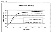
- Fig. 21 is a graph showing recorded surface temperatures of upper and lower ends of a balloon of the catheter having the shaft for an ablation catheter with a balloon in COMPARATIVE EXAMPLE.
- a shaft for an ablation catheter with a balloon is a shaft for an ablation catheter with a balloon formed of a single pipe and includes two lumens communicating from a distal end to a proximal end, wherein the first lumen is a guidewire passing lumen provided to allow a guidewire to pass therethrough, and the second lumen is a liquid supplying lumen provided to supply a liquid to an interior of a balloon of the ablation catheter with a balloon.
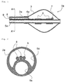
- Fig. 1 is a schematic view showing a cross-section horizontal with a longitudinal direction of a balloon portion of an ablation catheter with a balloon having a shaft for an ablation catheter with a balloon according to a first embodiment of the present invention.
- Fig. 2 is a schematic view showing a cross-section perpendicular to the longitudinal direction of the shaft for an ablation catheter with a balloon according to the first embodiment of the present invention.
- a shaft for an ablation catheter with a balloon 2a of the ablation catheter with a balloon whose balloon portion 1a is shown in Fig. 1 is formed of a single pipe.
- a balloon 3 is attached to a front side of the shaft for an ablation catheter with a balloon 2a.
- the shaft for an ablation catheter with a balloon 2a includes a guidewire passing lumen 5a that does not communicate with an interior of the balloon 3 and penetrates a shaft for an ablation catheter with a balloon 2 to a front end and a liquid supplying lumen 6a that communicates with the interior of the balloon 3.
- An electrode 4 is fixed to the shaft for an ablation catheter with a balloon 2a in the interior of the balloon 3.
- a temperature sensor 7 for measuring a temperature in the balloon is fixed to the electrode 4.
- a radio-frequency carrying lead wire 8 connected to the electrode 4 and a temperature sensor lead wire 9 connected to the temperature sensor 7 pass through the liquid supplying lumen 6a as shown in Fig. 2 , which shows the cross-section A-A' in Fig. 1 .
- the single pipe means a tube body that is formed of one tube or in which plural tubes contact without sliding with one another.
- Materials for the plural tubes constituting the signal pipe may be the same as or different from one another.
- Fig. 3 is a schematic view showing a cross-section perpendicular to a longitudinal direction of a shaft for an ablation catheter with a balloon constituted by plural tubes according to a second embodiment of the present invention.
- tubes 10a and 10b for forming layer structures on an inner surface of a guidewire passing lumen 5b and an inner surface of a liquid supplying lumen 6b and an embedded tube 11 contact without sliding with one another.
- the lead wire 8 and the temperature sensor lead wire 9 may be inserted into the embedded tube 11 .
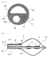
- Fig. 4 is a schematic view showing a cross-section horizontal with a longitudinal direction of a balloon portion of an ablation catheter with a balloon having a shaft for an ablation catheter with a balloon according to a third embodiment of the present invention.
- Fig. 5 is a schematic view showing a cross-section perpendicular to the longitudinal direction of the shaft for an ablation catheter with a balloon according to the third embodiment of the present invention.
- a shaft for an ablation catheter with a balloon 2c of the ablation catheter with a balloon whose balloon portion 1c is shown in Fig. 4 is formed of a single pipe and includes a guidewire passing lumen 5c that does not communicate with the interior of the balloon 3 and penetrates the shaft for an ablation catheter with a balloon 2c to a front end and a liquid supplying lumen 6c that communicates with the interior of the balloon 3.
- the shaft for an ablation catheter with a balloon 2c is inserted into an outer cylinder shaft 12 to constitute a double-cylinder shaft in which the shaft for an ablation catheter with a balloon 2c is slidable in a longitudinal direction.
- a rear portion of the balloon 3 is fixed to a front portion in a longitudinal direction of the outer cylinder shaft 12 while a front portion of the balloon 3 is fixed to a front end in the longitudinal direction of the shaft for an ablation catheter with a balloon 2c.
- the electrode 4 is fixed to the shaft for an ablation catheter with a balloon 2c in the interior of the balloon 3.
- the temperature sensor 7 for measuring a temperature in the balloon is fixed to the electrode 4.
- the radio-frequency carrying lead wire 8 connected to the electrode 4 and the temperature sensor lead wire 9 connected to the temperature sensor 7 pass through the liquid supplying lumen 6c as shown in Fig. 5 , which shows the cross-section A-A' in Fig. 4 .
- a material for the shafts for an ablation catheter with a balloon 2a, 2b, and 2c, the tubes 10a and 10b, and the embedded tube 11 is preferably a flexible material with excellent antithrombogenicity such as a polyamide resin represented by nylon 11 or nylon 12, polyamide elastomer, polyolefin represented by polypropylene or polyethylene, polyester represented by polyethylene terephthalate, polyurethane, or vinyl chloride.
- a material for the balloon 3 is preferably a flexible material with excellent antithrombogenicity and is more preferably a polyurethane polymeric material.
- polyurethane polymeric material examples include thermoplastic polyether urethane, polyether polyurethane urea, fluorine polyether urethane urea, a polyether polyurethane urea resin, and polyether polyurethane urea amide.
- the film thickness of the balloon 3 is preferably 20 to 150 microns and is more preferably 20 to 100 microns from a viewpoint of close contact with an affected tissue.
- an appropriate diameter has only to be selected depending on the target to be ablated, and the diameter is preferably 20 to 40 mm in a case of treatment of an arrhythmia, for example.
- the shape of the balloon 3 is preferably a tapered conical outer shape and is more preferably a spherical shape.
- Examples of a method for fixing the electrode 4 to the shaft for an ablation catheter with a balloon 2a, 2b, or 2c include caulking, adhesive, welding, and a heat shrinkable tube.
- the balloon is heated by supplying one or plural electrodes 4 fixed to the interior of the balloon 3 with radio-frequency power by a radio-frequency generator.
- a unipolar method in which the balloon is heated by supplying the radio-frequency power by the radio-frequency generator between one electrode 4 fixed to the interior of the balloon 3 and a counter electrode plate attached to a surface of a patient's body, may be adopted.
- the shape of the electrode 4 is not particularly limited and is preferably a tubular shape such as a coiled shape or a cylindrical shape.
- the diameter of an electric wire of the coiled electrode is preferably 0.05 to 0.5 mm from a viewpoint of practicality.
- a material for the electrode 4 is preferably a highly conductive metal.
- highly conductive metal examples include highly conductive metals such as silver, gold, platinum, and copper.
- Examples of a method for fixing the temperature sensor 7 and the lead wire 8 to the electrode 4 include soldering, caulking, and welding.
- Examples of the temperature sensor 7 include a thermocouple and a resistance-temperature detector.
- the temperature sensor 7 is fixed to the shaft for an ablation catheter with a balloon 2a, 2b, or 2c, the electrode 4, or an inner surface of the balloon 3.
- Plural temperature sensors 7 may be fixed from a viewpoint of backup in a case of a failure of the temperature sensor.
- the diameter of the lead wire 8 is not particularly limited and is preferably 0.05 to 0.8 mm from a viewpoint of practicality.
- Examples of a material for the lead wire 8 include highly conductive electric wires such as copper, silver, gold, platinum, tungsten, and an alloy.
- the lead wire 8 is preferably provided with an electrical insulating protective coat such as a fluorine resin from a viewpoint of preventing short circuit, and it is more preferable to form a part of the lead wire 8, from which the electrical insulating protective coat has been stripped away, in a coiled shape and use the part as the electrode 4 from a viewpoint of dispensing with connection by soldering, caulking, or welding.
- the diameter of the temperature sensor lead wire 9 is preferably 0.05 to 0.5 mm from a viewpoint of practicality.
- a material for the temperature sensor lead wire 9 is preferably the same material as that for the thermocouple, and examples of the material include copper and constantan when the temperature sensor 8 is a T-shaped thermocouple.
- a material for the temperature sensor lead wire 9 is preferably a highly conductive electric wire such as copper, silver, gold, platinum, tungsten, or an alloy.
- the temperature sensor lead wire 9 is preferably provided with an electrical insulating protective coat such as a fluorine resin from a viewpoint of preventing short circuit.
- a value (La/Li) derived by dividing a length (La) of an outline of a shape of the liquid supplying lumen in a cross-section perpendicular to a longitudinal direction of the single pipe by a length (Li) of a circumference of a circle having an equal area to an area of a liquid supplying lumen region surrounded by the outline is 1 to 2.3, and the area of the liquid supplying lumen region is 2.0 to 4.5 mm 2 .
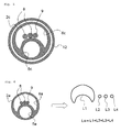
- Fig. 6 illustrates a length (La) of an outline of a shape of the liquid supplying lumen in a cross-section perpendicular to a longitudinal direction of the shaft for an ablation catheter with a balloon according to the first embodiment of the present invention.
- Fig. 7 illustrates an area of a liquid supplying lumen region surrounded by the outline of the shape of the liquid supplying lumen in the cross-section perpendicular to the longitudinal direction of the shaft for an ablation catheter with a balloon according to the first embodiment of the present invention.
- the liquid for heating to be supplied to the interior of the balloon 3 passes through the liquid supplying lumen 6a.
- the outline of the shape of the liquid supplying lumen is L1, which is an inner circumference of the liquid supplying lumen 6a, L2 and L3, which are outer circumferences of the lead wires 8, and L4, which is an outer circumference of the temperature sensor lead wire 9, and "the length (La) of the outline of the shape of the liquid supplying lumen" refers to a value of a total length of L1, L2, L3, and L4.
- Li refers to a length of a circumference of a circle having an equal area to the area of the liquid supplying lumen region surrounded by the outline of the shape of the liquid supplying lumen, that is, the area of the colored part shown on the right side of Fig. 7 .
- a value derived by dividing La by Li, that is, La/Li, is preferably 1 to 2.3 and is more preferably 1 to 1.8 from a viewpoint of allowing the liquid such as saline to pass more smoothly.
- the area of the liquid supplying lumen region is preferably 2.0 to 4.5 mm 2 from a viewpoint of securing insertability of the ablation catheter with a balloon in the patient's body as well as allowing the liquid such as saline to pass more smoothly.
- an ablation catheter system with a balloon according to the present invention includes the shaft for an ablation catheter with a balloon according to the present invention.
- Fig. 8 is a schematic view showing an example of an ablation catheter system with a balloon according to the present invention.
- a shaft for an ablation catheter with a balloon 2d of an ablation catheter system with a balloon 19 shown in Fig. 8 is formed of a single pipe.
- the balloon 3 is attached to a front side of the shaft for an ablation catheter with a balloon 2d.
- the shaft for an ablation catheter with a balloon 2d includes a guidewire passing lumen 5d that does not communicate with the interior of the balloon 3 and penetrates the shaft for an ablation catheter with a balloon 2d from a proximal end to a front end and a liquid supplying lumen 6d that penetrates the proximal end of the shaft for an ablation catheter with a balloon 2d and communicates with the interior of the balloon 3.
- an operating portion 13 To a proximal side of the shaft for an ablation catheter with a balloon 2d is attached an operating portion 13, and the operating portion 13 has lumens respectively corresponding to the guidewire passing lumen 5d and the liquid supplying lumen 6d of the shaft for an ablation catheter with a balloon 2.
- the liquid supplied to the interior of the balloon 3 and the like can be vibrated and mixed by a mixing generator 16 connected to the operating portion 13.
- a bifurcated connector 17 that bifurcates this lumen and communicates with the guidewire passing lumen 5d.
- a guidewire 14 passes through the guidewire passing lumen 5d via the bifurcated connector 17.
- an infusion pump 18 so that, even in a case where the shaft for an ablation catheter with a balloon 2d is inserted into a blood vessel of the patient, regurgitation of blood can be prevented by supplying the guidewire passing lumen 5d with glucose or saline from the infusion pump 18. Meanwhile, instead of using the infusion pump 18, the glucose or saline may be supplied to the guidewire passing lumen 5d by dripping with use of free fall such as a drip infusion.
- the electrode 4 is fixed to the shaft for an ablation catheter with a balloon 2d in the interior of the balloon 3.
- the temperature sensor 7 for measuring a temperature in the balloon is fixed to the electrode 4.
- the radio-frequency carrying lead wire 8 connected to the electrode 4 and the temperature sensor lead wire 9 connected to the temperature sensor 7 pass through the shaft for an ablation catheter with a balloon 2d and the operating portion 13 and are connected to a radio-frequency generator 15.
- the balloon 3 is heated by supplying the electrode 4 with radio-frequency power by the radio-frequency generator. At the same time as heating the balloon 3, the liquid in the balloon 3 and the like is vibrated and mixed by the mixing generator 16, a surface temperature of the balloon 3 is uniformed, and then the balloon 3 is brought into contact with the affected tissue for treatment.
- the guidewire 14 preferably has a tip shape that will not damage intracorporeal tissues at the time of being inserted into the patient's body.
- the frequency of the radio-frequency power to be supplied from the radio-frequency generator 15 is preferably 100 kHz or higher from a viewpoint of preventing an electric shock of the patient.
- Examples of the mixing generator 16 include a roller pump, a diaphragm pump, and a bellows pump, and the radio-frequency generator 15 and the mixing generator 16 are preferably integrated from a viewpoint of reducing the number of components of the ablation catheter system with a balloon according to the present invention.
- An example of the bifurcated connector 17 is a Y-shaped connector.
- the Y-shaped connector preferably has a valve mechanism from a viewpoint of preventing leakage of the liquid to be supplied to expand the balloon 3.
- a length represents a length in a longitudinal direction.
- a part of a range including the liquid supplying lumen 6e and the third lumen 20 of the shaft for an ablation catheter with a balloon 2 from a front end of the shaft for an ablation catheter with a balloon 2e to a position 40 mm distanced in length from the front end was cut off to have the shape of the front portion shown in Fig. 9 .
- a copper wire plated with silver and undergoing FEP coating having a length of 1300 mm and a diameter of 0.72 mm was used as the lead wire 8
- a constantan wire undergoing FEP coating having a length of 1300 mm and a diameter of 0.29 mm was used as the temperature sensor lead wire 9.
- the coat in a 150 mm range in length from one tip of the lead wire 8 was stripped away, the coat in a 3 mm range in length from one tip of the temperature sensor lead wire 9 was stripped away, and the tips from which the coats were stripped away were overlapped in a range of 1 mm in length of each wire and were fixed by soldering.
- the temperature sensor lead wire 9 was inserted into the third lumen 20, and the fixed part of the tips of the lead wire 8 and the temperature sensor lead wire 9 was placed at a position 20 mm distanced in length from the front end of the shaft for an ablation catheter with a balloon 2e. With the position set as a starting point, the lead wire 8 was directly wound around the shaft for an ablation catheter with a balloon 2e and the temperature sensor lead wire 9 in a proximal direction of the ablation catheter with a balloon to form a coiled shape having a length in the longitudinal direction of 10 mm and use it as an electrode-cum-temperature sensor 21.
- a remainder of the lead wire 8 after its part was formed in the coiled shape was inserted into the third lumen 20 along the temperature sensor lead wire 9, and the third lumen 20 into which the lead wire 8 and the temperature sensor lead wire 9 were inserted was sealed by filling epoxy adhesive.
- the balloon 3 made of polyurethane formed in a spherical shape having a diameter of 25 mm and a thickness of 40 ⁇ m and having at both ends neck portions one having a length of 15 mm and an inner diameter of 3.2 mm and the other having a length of 15 mm and an inner diameter of 1.6 mm was prepared by dipping.
- the neck portion of the balloon 3 having an inner diameter of 3.2 mm was thermally welded on an outer circumference of the front portion of the shaft for an ablation catheter with a balloon 2e, and the neck portion of the balloon 3 having an inner diameter of 1.6 mm was thermally welded so that the liquid supplying lumen 6e of the shaft for an ablation catheter with a balloon 2e would communicate with the interior of the balloon 3.
- FIG. 10 shows its balloon portion 1e.
- the area of the liquid supplying lumen region of EXAMPLE 1 catheter was 2.01 mm 2 , and La/Li was 1.00.
- a shaft made of polyurethane having a length of 1000 mm and an outer diameter of 3.2 mm and having a guidewire passing lumen 5f with a cross-section perpendicular to a longitudinal direction of the shaft being a circle having a diameter of 1.1 mm and a liquid supplying lumen 6f with a cross-section perpendicular to the longitudinal direction of the shaft being a circle having a diameter of 1.8 mm was prepared by extrusion molding to obtain a shaft for an ablation catheter with a balloon 2f.
- a part of a range including the liquid supplying lumen 6f of the shaft for an ablation catheter with a balloon 2f from a front end of the shaft for an ablation catheter with a balloon 2f to a position 40 mm distanced in length from the front end was cut off to have the shape of the front portion shown in Fig. 11 .
- a copper wire plated with silver and undergoing FEP coating having a length of 1300 mm and a diameter of 0.72 mm was used as the lead wire 8
- a constantan wire undergoing FEP coating having a length of 1300 mm and a diameter of 0.29 mm was used as the temperature sensor lead wire 9.
- the coat in a 150 mm range in length from one tip of the lead wire 8 was stripped away, the coat in a 3 mm range in length from one tip of the temperature sensor lead wire 9 was stripped away, and the tips from which the coats were stripped away were overlapped in a range of 1 mm in length of each wire and were fixed by soldering.
- the temperature sensor lead wire 9 was inserted into the liquid supplying lumen 6f, and the fixed part of the tips of the lead wire 8 and the temperature sensor lead wire 9 was placed at a position 20 mm distanced in length from the front end of the shaft for an ablation catheter with a balloon 2f. With the position set as a starting point, the lead wire 8 was directly wound around the shaft for an ablation catheter with a balloon 2f and the temperature sensor lead wire 9 in a proximal direction of the ablation catheter with a balloon to form a coiled shape having a length in the longitudinal direction of 10 mm and use it as the electrode-cum-temperature sensor 21.
- a remainder of the lead wire 8 after its part was formed in the coiled shape was inserted into the liquid supplying lumen 6f along the temperature sensor lead wire 9.
- the balloon 3 made of polyurethane formed in a spherical shape having a diameter of 25 mm and a thickness of 40 ⁇ m and having at both ends neck portions one having a length of 15 mm and an inner diameter of 3.2 mm and the other having a length of 15 mm and an inner diameter of 1.6 mm was prepared by dipping.
- the neck portion of the balloon 3 having an inner diameter of 3.2 mm was thermally welded on an outer circumference of the front portion of the shaft for an ablation catheter with a balloon 2f, and the neck portion of the balloon 3 having an inner diameter of 1.6 mm was thermally welded so that the liquid supplying lumen 6f of the shaft for an ablation catheter with a balloon 2f would communicate with the interior of the balloon 3.
- FIG. 12 shows its balloon portion 1f.
- the area of the liquid supplying lumen region of EXAMPLE 2 catheter was 2.07 mm 2 , and La/Li was 1.73.
- a shaft made of polyurethane having a length of 1000 mm and an outer diameter of 3.6 mm and having a guidewire passing lumen 5g with a cross-section perpendicular to a longitudinal direction of the shaft being a circle having a diameter of 1.2 mm and a liquid supplying lumen 6g with a cross-section perpendicular to the longitudinal direction of the shaft being a semicircle having a diameter of 2.7 mm was prepared by extrusion molding to obtain a shaft for an ablation catheter with a balloon 2g.
- a part of a range including the liquid supplying lumen 6g of the shaft for an ablation catheter with a balloon 2g from a front end of the shaft for an ablation catheter with a balloon 2g to a position 40 mm distanced in length from the front end was cut off to have the shape of the front portion shown in Fig. 13 .
- a copper wire plated with silver and undergoing FEP coating having a length of 1300 mm and a diameter of 0.72 mm was used as the lead wire 8
- a constantan wire undergoing FEP coating having a length of 1300 mm and a diameter of 0.72 mm was used as a temperature sensor lead wire 9g.
- the coat in a 150 mm range in length from one tip of the lead wire 8 was stripped away, the coat in a 3 mm range in length from one tip of the temperature sensor lead wire 9g was stripped away, and the tips from which the coats were stripped away were overlapped in a range of 1 mm in length of each wire and were fixed by soldering.
- the temperature sensor lead wire 9g was inserted into the liquid supplying lumen 6g, and the fixed part of the tips of the lead wire 8 and the temperature sensor lead wire 9g was placed at a position 20 mm distanced in length from the front end of the shaft for an ablation catheter with a balloon 2g. With the position set as a starting point, the lead wire 8 was directly wound around the shaft for an ablation catheter with a balloon 2g and the temperature sensor lead wire 9g in a proximal direction of the ablation catheter with a balloon to form a coiled shape having a length in the longitudinal direction of 10 mm and use it as the electrode-cum-temperature sensor 21.
- a remainder of the lead wire 8 after its part was formed in the coiled shape was inserted into the liquid supplying lumen 6g along the temperature sensor lead wire 9g.
- the balloon 3 made of polyurethane formed in a spherical shape having a diameter of 25 mm and a thickness of 40 ⁇ m and having at both ends neck portions one having a length of 15 mm and an inner diameter of 3.2 mm and the other having a length of 15 mm and an inner diameter of 1.6 mm was prepared by dipping.
- the neck portion of the balloon 3 having an inner diameter of 3.2 mm was thermally welded on an outer circumference of the front portion of the shaft for an ablation catheter with a balloon 2g, and the neck portion of the balloon 3 having an inner diameter of 1.6 mm was thermally welded so that the liquid supplying lumen 6g of the shaft for an ablation catheter with a balloon 2g would communicate with the interior of the balloon 3.
- FIG. 14 shows its balloon portion 1g.
- the area of the liquid supplying lumen region of EXAMPLE 3 catheter was 2.05 mm 2 , and La/Li was 2.26.
- a tube made of polyurethane having a length of 960 mm, an outer diameter of 3.2 mm, and an inner diameter of 2.4 mm was prepared as an outer cylinder shaft 22, and a tube made of diamide having a length of 1000 mm, an outer diameter of 1.6 mm, and an inner diameter of 1.2 mm was prepared as an inner cylinder shaft 23.
- a copper wire plated with silver and undergoing FEP coating having a length of 1300 mm and a diameter of 0.72 mm was used as the lead wire 8
- a constantan wire undergoing FEP coating having a length of 1300 mm and a diameter of 0.29 mm was used as the temperature sensor lead wire 9.
- the coat in a 150 mm range in length from one tip of the lead wire 8 was stripped away, the coat in a 3 mm range in length from one tip of the temperature sensor lead wire 9 was stripped away, and the tips from which the coats were stripped away were overlapped in a range of 1 mm in length of each wire and were fixed by soldering.
- the fixed part of the tips of the lead wire 8 and the temperature sensor lead wire 9 was placed at a position 20 mm distanced in length from a front end of the inner cylinder shaft 23. With the position set as a starting point, the lead wire 8 was directly wound around the inner cylinder shaft 23 and the temperature sensor lead wire 9 in a proximal direction of the ablation catheter with a balloon to form a coiled shape having a length in the longitudinal direction of 10 mm and use it as the electrode-cum-temperature sensor 21.
- the inner cylinder shaft 23 forming the electrode-cum-temperature sensor 21 at a front portion was inserted into the outer cylinder shaft 22 so that a part of the inner cylinder shaft 23 in a 40 mm range in length from its front end would be projected from the outer cylinder shaft 22.
- the balloon 3 made of polyurethane formed in a spherical shape having a diameter of 25 mm and a thickness of 40 ⁇ m and having at both ends neck portions one having a length of 15 mm and an inner diameter of 3.2 mm and the other having a length of 15 mm and an inner diameter of 1.6 mm was prepared by dipping.
- a front portion of the balloon 3 was thermally welded on an outer circumference of the front portion of the inner cylinder shaft 23, and a rear portion of the balloon 3 was thermally welded on an outer circumference of a front portion of the outer cylinder shaft 22.
- Fig. 15 shows its balloon portion 1h.
- the area of the liquid supplying lumen region of COMPARATIVE EXAMPLE catheter was 2.04 mm 2 , and La/Li was 3.11.
- a deflating operation was conducted for each of the ablation catheters with a balloon prepared in EXAMPLES 1 to 3 and COMPARATIVE EXAMPLE, and the number of times of operation until no remaining air existed was compared.
- a contrast medium Hexabrix 320
- 0.9% saline volume ratio 1:1
- the ablation catheter with a balloon having the shaft for an ablation catheter with a balloon according to the present invention enables complete deflation and prevents the possibility of mixing of air in the blood vessel of the patient even in a case where the balloon is damaged during the treatment to assure sufficient safety.
- Water having a predetermined flow rate was made to pass through each of the shafts of the ablation catheters with a balloon prepared in EXAMPLES 1 to 3 and COMPARATIVE EXAMPLE with use of a roller pump to measure and compare water pressure in the shaft.
- Fig. 16 is a schematic view of an in-shaft water pressure testing system (a test example of the ablation catheter with a balloon having the shaft for an ablation catheter with a balloon 2).
- the front end of each of the shafts of the ablation catheters with a balloon prepared in EXAMPLES 1 to 3 and COMPARATIVE EXAMPLE to which no balloon was attached was immersed into water in a water tank 30.
- the bifurcated connector 17 was connected to the operating portion to communicate with the liquid supplying lumen or a space between the inner cylinder shaft and the outer cylinder shaft. To the bifurcated connector 17 were connected a roller pump 31 and a pressure gauge 32.
- Water pumped up from the water tank 30 with use of the roller pump 31 was supplied via the operating portion at a flow velocity of 10 mL/second to pass through the liquid supplying lumen or the space between the inner cylinder shaft and the outer cylinder shaft, and a value of the pressure gauge 32 at that time was read off.
- the water pressure of EXAMPLE 1 catheter was 77 kPa
- the water pressure of EXAMPLE 2 catheter was 92 kPa
- the water pressure of EXAMPLE 3 catheter was 106 kPa
- the water pressure of COMPARATIVE EXAMPLE catheter was 132 kPa.
- the shaft for an ablation catheter with a balloon according to the present invention is shaped to allow the liquid such as saline to pass therethrough more smoothly and to improve the mixing efficiency, which leads to quick uniforming of the surface temperature of the balloon and suppression of remaining air.
- Each electrode 4 of the ablation catheters with a balloon prepared in EXAMPLES 1 to 3 and COMPARATIVE EXAMPLE was supplied with radio-frequency power by the radio-frequency generator to compare the surface temperatures of upper and lower ends of the balloon.
- Fig. 17 is a schematic view of a balloon surface temperature testing system.
- the radio-frequency generator 15 one into which the mixing generator 16 has been integrated
- thermocouples 36 were respectively arranged at an upper end and a lower end in a vertical direction of an outline contacted by an outer circumference of a maximum diameter of the balloon 3 expanded so that the maximum diameter thereof might be 25 mm, and the thermocouples 36 were connected to a temperature data logger 35.
- EXAMPLE 1 catheter, EXAMPLE 2 catheter, EXAMPLE 3 catheter, and COMPARATIVE EXAMPLE catheter was connected to the radio-frequency generator 15 and the mixing generator 16 and was immersed into the 0.9% saline in the water tank 30, the balloon 3 was expanded by a mixed solution of a contrast medium (Hexabrix 320) and 0.9% saline (volume ratio 1:1) so that the maximum diameter thereof might be 25 mm, and each catheter was fit into the pseudo affected tissue 34.
- a contrast medium Hex 320
- 0.9% saline volume ratio 1:1
- the liquid in the balloon and the like was vibrated and mixed by the mixing generator 16 at a volume per single supply/discharge of 0.4 mL and at a vibration frequency of 1 Hz.
- the surface temperatures of the upper and lower ends of the balloon were recorded at a sampling period of 1 second by the temperature data logger 35.
- An average value of a surface temperature difference between the upper end temperature and the lower end temperature of the balloon in EXAMPLE 1 catheter during supply of the radio-frequency power was 0.2°C
- the average value in EXAMPLE 2 catheter was 0.4°C
- the average value in EXAMPLE 3 catheter was 0.8°C.
- a period of time from a time point when the surface temperature of one of the upper and lower ends of the balloon exceeded 60°C, which is an optimal temperature for ablation for treatment of an atrial fibrillation, to a time point when the surface temperature of the other exceeded 60°C during supply of the radio-frequency power to EXAMPLE 1 catheter was 6 seconds
- the period in the case of EXAMPLE 2 catheter was 15 seconds
- the period in the case of EXAMPLE 3 catheter was 26 seconds.
- the average value of the surface temperature difference between the upper end temperature and the lower end temperature of the balloon in COMPARATIVE EXAMPLE catheter during supply of the radio-frequency power was 3.6°C. Also, during supply of the radio-frequency power to COMPARATIVE EXAMPLE catheter, the temperature of the upper end of the balloon exceeded 60°C, but the temperature of the lower end of the balloon was not stable and did not exceed 60°C. Further, the surface temperature difference between the upper end temperature and the lower end temperature of the balloon tended to be large as time passed.
- the shaft for an ablation catheter with a balloon according to the present invention can uniform the surface temperature of the balloon quickly, which leads to decrease in burden on the patient and improvement in treatment accuracy.
- the present invention can be used as a shaft for an ablation catheter with a balloon for ablation of a target lesion location.
Landscapes
- Health & Medical Sciences (AREA)
- Life Sciences & Earth Sciences (AREA)
- Engineering & Computer Science (AREA)
- Surgery (AREA)
- Heart & Thoracic Surgery (AREA)
- Veterinary Medicine (AREA)
- General Health & Medical Sciences (AREA)
- Biomedical Technology (AREA)
- Public Health (AREA)
- Animal Behavior & Ethology (AREA)
- Otolaryngology (AREA)
- Medical Informatics (AREA)
- Molecular Biology (AREA)
- Nuclear Medicine, Radiotherapy & Molecular Imaging (AREA)
- Plasma & Fusion (AREA)
- Physics & Mathematics (AREA)
- Cardiology (AREA)
- Anesthesiology (AREA)
- Biophysics (AREA)
- Hematology (AREA)
- Pulmonology (AREA)
- Child & Adolescent Psychology (AREA)
- Media Introduction/Drainage Providing Device (AREA)
- Surgical Instruments (AREA)
Abstract
Description
- The present invention relates to a shaft for an ablation catheter with a balloon.
- Catheter ablation is a treatment method by inserting an ablation catheter into a cardiac chamber and applying heat between a tip electrode and a counter electrode plate to ablate and remove a myocardial tissue causing an arrhythmia. The catheter ablation is useful mainly for treatment of tachyarrythmias such as a paroxysmal supraventricular tachycardia, an atrial tachycardia, an atrial flutter, and a paroxysmal ventricular tachycardia, and recently, an ablation catheter with a balloon having a balloon at the tip of a catheter tube is used (
Patent Literatures 1 and 2). - The ablation catheter with a balloon is a medical device of expanding a balloon fixed to the tip of a catheter by a liquid for heating and heating the liquid for heating by a radio-frequency current supplied from a radio-frequency generator to ablate the entire myocardial tissue contacting the surface of the balloon. The temperature of the balloon is adjusted, for example, by a vibration applying device, which applies a vibration to the liquid for heating filled in the balloon, and is controlled by a temperature sensor arranged in the balloon.
- As a means for uniforming the temperature of the liquid in the balloon,
Patent Literature 1 discloses an ablation catheter with a balloon having a double-pipe structure including an outer cylinder shaft and an inner cylinder shaft and mixing the liquid in the balloon by vibrating the liquid supplied in the balloon and in a space between the outer cylinder shaft and the inner cylinder shaft. -
- Patent Literature 1: Japanese Patent No.
3607231 - Patent Literature 2: Japanese Patent No.
3892438 - However, in the ablation catheter with a balloon disclosed in
Patent Literature 1, since the liquid for heating supplied in the balloon and in the space between the outer cylinder shaft and the inner cylinder shaft is not perfused smoothly, it takes a long time to uniform the surface temperature of the balloon, and a variation occurs in the surface temperature of the balloon, which causes concern about increase in burden on a patient and decrease in treatment accuracy. - Also, since the liquid for heating is not perfused smoothly, air bubbles are attached to the balloon, the inner surface of the outer cylinder shaft, and the outer surface of the inner cylinder shaft even when the liquid is supplied in the balloon and in the space between the outer cylinder shaft and the inner cylinder shaft before treatment to deflate the ablation catheter with a balloon, and complete deflation is difficult. Air remaining in the balloon and the like has an adverse effect on uniforming the surface temperature of the balloon and may be mixed in a blood vessel of the patient in a case where the balloon is damaged during the treatment, and thus complete deflation of the ablation catheter with a balloon is required in terms of assurance of the patient's safety.
- It is an object of the present invention to increase a mixing efficiency of a liquid for heating to be supplied to a balloon of an ablation catheter with a balloon to uniform a surface temperature of the balloon quickly, and prevent air from remaining in the ablation catheter with a balloon to enhance safety of treatment using the ablation catheter with a balloon.
- As a result of concerted study directed toward solving the aforementioned problem, the present inventors discovered the following inventions (1) to (4).
- (1) A shaft for an ablation catheter with a balloon formed of a single pipe comprising two lumens communicating from a distal end to a proximal end, wherein the first lumen is a guidewire passing lumen provided to allow a guidewire to pass therethrough, and the second lumen is a liquid supplying lumen provided to supply a liquid to an interior of a balloon of the ablation catheter with a balloon.
- (2) The shaft for an ablation catheter with a balloon according to the above (1), wherein a value (La/Li) derived by dividing a length (La) of an outline of a shape of the liquid supplying lumen in a cross-section perpendicular to a longitudinal direction of the single pipe by a length (Li) of a circumference of a circle having an equal area to an area of a liquid supplying lumen region surrounded by the outline is 1 to 2.3, and the area of the liquid supplying lumen region is 2.0 to 4.5 mm2.
- (3) The shaft for an ablation catheter with a balloon according to the above (1) or (2), wherein a value (La/Li) derived by dividing a length (La) of an outline of a shape of the liquid supplying lumen in a cross-section perpendicular to a longitudinal direction of the single pipe by a length (Li) of a circumference of a circle having an equal area to an area of a liquid supplying lumen region surrounded by the outline is 1 to 1.8.
- (4) An ablation catheter system with a balloon comprising the shaft for an ablation catheter with a balloon according to any one of the above (1) to (3).
- With the present invention, at the time of treatment with use of an ablation catheter with a balloon, it is possible to allow a liquid for heating to be supplied to an interior of a balloon to pass through a liquid supplying lumen provided in a shaft for an ablation catheter with a balloon more smoothly, which enables to increase a mixing efficiency of the liquid for heating. Also, with the present invention, it takes a short time to uniform a surface temperature of the balloon to decrease a burden on a patient, and air is prevented from remaining in the ablation catheter with a balloon to achieve enhanced safety and a high treatment effect.
-
-
Fig. 1 is a schematic view showing a cross-section horizontal with a longitudinal direction of a balloon portion of an ablation catheter with a balloon having a shaft for an ablation catheter with a balloon according to a first embodiment of the present invention. -
Fig. 2 is a schematic view showing a cross-section perpendicular to the longitudinal direction of the shaft for an ablation catheter with a balloon according to the first embodiment of the present invention. -
Fig. 3 is a schematic view showing a cross-section perpendicular to a longitudinal direction of a shaft for an ablation catheter with a balloon according to a second embodiment of the present invention. -
Fig. 4 is a schematic view showing a cross-section horizontal with a longitudinal direction of a balloon portion of an ablation catheter with a balloon having a shaft for an ablation catheter with a balloon according to a third embodiment of the present invention. -
Fig. 5 is a schematic view showing a cross-section perpendicular to the longitudinal direction of the shaft for an ablation catheter with a balloon according to the third embodiment of the present invention. -
Fig. 6 illustrates a length (La) of an outline of a shape of a liquid supplying lumen in the cross-section perpendicular to the longitudinal direction of the shaft for an ablation catheter with a balloon according to the first embodiment of the present invention. -
Fig. 7 illustrates an area of a liquid supplying lumen region surrounded by the outline of the shape of the liquid supplying lumen in the cross-section perpendicular to the longitudinal direction of the shaft for an ablation catheter with a balloon according to the first embodiment of the present invention. -
Fig. 8 is a schematic view showing an example of an ablation catheter system with a balloon according to the present invention. -
Fig. 9 is a schematic view showing a cross-section horizontal with and a cross-section perpendicular to a longitudinal direction of a front portion of a shaft for an ablation catheter with a balloon in EXAMPLE 1. -
Fig. 10 is a schematic view showing a cross-section horizontal with and a cross-section perpendicular to a longitudinal direction of a balloon portion of a catheter having the shaft for an ablation catheter with a balloon in -
Fig. 11 is a schematic view showing a cross-section horizontal with and a cross-section perpendicular to a longitudinal direction of a front portion of a shaft for an ablation catheter with a balloon in EXAMPLE 2. -
Fig. 12 is a schematic view showing a cross-section horizontal with and a cross-section perpendicular to a longitudinal direction of a balloon portion of a catheter having the shaft for an ablation catheter with a balloon in -
Fig. 13 is a schematic view showing a cross-section horizontal with and a cross-section perpendicular to a longitudinal direction of a front portion of a shaft for an ablation catheter with a balloon in EXAMPLE 3. -
Fig. 14 is a schematic view showing a cross-section horizontal with and a cross-section perpendicular to a longitudinal direction of a balloon portion of a catheter having the shaft for an ablation catheter with a balloon in -
Fig. 15 is a schematic view showing a cross-section horizontal with and a cross-section perpendicular to a longitudinal direction of a balloon portion of a catheter having a shaft for an ablation catheter with a balloon in -
Fig. 16 is a schematic view of an in-shaft water pressure testing system. -
Fig. 17 is a schematic view of a balloon surface temperature testing system. -
Fig. 18 is a graph showing recorded surface temperatures of upper and lower ends of a balloon of the catheter having the shaft for an ablation catheter with a balloon in EXAMPLE 1. -
Fig. 19 is a graph showing recorded surface temperatures of upper and lower ends of a balloon of the catheter having the shaft for an ablation catheter with a balloon in EXAMPLE 2. -
Fig. 20 is a graph showing recorded surface temperatures of upper and lower ends of a balloon of the catheter having the shaft for an ablation catheter with a balloon in EXAMPLE 3. -
Fig. 21 is a graph showing recorded surface temperatures of upper and lower ends of a balloon of the catheter having the shaft for an ablation catheter with a balloon in COMPARATIVE EXAMPLE. - Preferred embodiments of the present invention will be described below with reference to the accompanying drawings, but the present invention is not limited to these embodiments. Like reference characters designate similar or identical parts throughout the several views thereof, and duplicate explanation is omitted. Also, the ratio in the drawings does not necessarily correspond to an actual ratio.
- A shaft for an ablation catheter with a balloon according to the present invention is a shaft for an ablation catheter with a balloon formed of a single pipe and includes two lumens communicating from a distal end to a proximal end, wherein the first lumen is a guidewire passing lumen provided to allow a guidewire to pass therethrough, and the second lumen is a liquid supplying lumen provided to supply a liquid to an interior of a balloon of the ablation catheter with a balloon.
-
Fig. 1 is a schematic view showing a cross-section horizontal with a longitudinal direction of a balloon portion of an ablation catheter with a balloon having a shaft for an ablation catheter with a balloon according to a first embodiment of the present invention.Fig. 2 is a schematic view showing a cross-section perpendicular to the longitudinal direction of the shaft for an ablation catheter with a balloon according to the first embodiment of the present invention. - A shaft for an ablation catheter with a
balloon 2a of the ablation catheter with a balloon whoseballoon portion 1a is shown inFig. 1 is formed of a single pipe. Aballoon 3 is attached to a front side of the shaft for an ablation catheter with aballoon 2a. Also, the shaft for an ablation catheter with aballoon 2a includes aguidewire passing lumen 5a that does not communicate with an interior of theballoon 3 and penetrates a shaft for an ablation catheter with aballoon 2 to a front end and a liquid supplyinglumen 6a that communicates with the interior of theballoon 3. - An
electrode 4 is fixed to the shaft for an ablation catheter with aballoon 2a in the interior of theballoon 3. Atemperature sensor 7 for measuring a temperature in the balloon is fixed to theelectrode 4. A radio-frequency carryinglead wire 8 connected to theelectrode 4 and a temperaturesensor lead wire 9 connected to thetemperature sensor 7 pass through the liquid supplyinglumen 6a as shown inFig. 2 , which shows the cross-section A-A' inFig. 1 . - "The single pipe" means a tube body that is formed of one tube or in which plural tubes contact without sliding with one another.
- Materials for the plural tubes constituting the signal pipe may be the same as or different from one another.
-
Fig. 3 is a schematic view showing a cross-section perpendicular to a longitudinal direction of a shaft for an ablation catheter with a balloon constituted by plural tubes according to a second embodiment of the present invention. - In a shaft for an ablation catheter with a
balloon 2b shown inFig. 3 ,tubes guidewire passing lumen 5b and an inner surface of a liquid supplyinglumen 6b and an embeddedtube 11 contact without sliding with one another. - Into the embedded
tube 11 may be inserted thelead wire 8 and the temperaturesensor lead wire 9 collectively, as shown inFig. 3 . -
Fig. 4 is a schematic view showing a cross-section horizontal with a longitudinal direction of a balloon portion of an ablation catheter with a balloon having a shaft for an ablation catheter with a balloon according to a third embodiment of the present invention.Fig. 5 is a schematic view showing a cross-section perpendicular to the longitudinal direction of the shaft for an ablation catheter with a balloon according to the third embodiment of the present invention. - A shaft for an ablation catheter with a
balloon 2c of the ablation catheter with a balloon whose balloon portion 1c is shown inFig. 4 is formed of a single pipe and includes a guidewire passing lumen 5c that does not communicate with the interior of theballoon 3 and penetrates the shaft for an ablation catheter with aballoon 2c to a front end and a liquid supplyinglumen 6c that communicates with the interior of theballoon 3. - The shaft for an ablation catheter with a
balloon 2c is inserted into anouter cylinder shaft 12 to constitute a double-cylinder shaft in which the shaft for an ablation catheter with aballoon 2c is slidable in a longitudinal direction. A rear portion of theballoon 3 is fixed to a front portion in a longitudinal direction of theouter cylinder shaft 12 while a front portion of theballoon 3 is fixed to a front end in the longitudinal direction of the shaft for an ablation catheter with aballoon 2c. - The
electrode 4 is fixed to the shaft for an ablation catheter with aballoon 2c in the interior of theballoon 3. Thetemperature sensor 7 for measuring a temperature in the balloon is fixed to theelectrode 4. The radio-frequency carryinglead wire 8 connected to theelectrode 4 and the temperaturesensor lead wire 9 connected to thetemperature sensor 7 pass through the liquid supplyinglumen 6c as shown inFig. 5 , which shows the cross-section A-A' inFig. 4 . - A material for the shafts for an ablation catheter with a
balloon tubes tube 11 is preferably a flexible material with excellent antithrombogenicity such as a polyamide resin represented bynylon 11 ornylon 12, polyamide elastomer, polyolefin represented by polypropylene or polyethylene, polyester represented by polyethylene terephthalate, polyurethane, or vinyl chloride. - A material for the
balloon 3 is preferably a flexible material with excellent antithrombogenicity and is more preferably a polyurethane polymeric material. - Examples of the polyurethane polymeric material include thermoplastic polyether urethane, polyether polyurethane urea, fluorine polyether urethane urea, a polyether polyurethane urea resin, and polyether polyurethane urea amide.
- The film thickness of the
balloon 3 is preferably 20 to 150 microns and is more preferably 20 to 100 microns from a viewpoint of close contact with an affected tissue. - As for the diameter of the
balloon 3, an appropriate diameter has only to be selected depending on the target to be ablated, and the diameter is preferably 20 to 40 mm in a case of treatment of an arrhythmia, for example. - The shape of the
balloon 3 is preferably a tapered conical outer shape and is more preferably a spherical shape. - Examples of a method for fixing the
electrode 4 to the shaft for an ablation catheter with aballoon - The balloon is heated by supplying one or
plural electrodes 4 fixed to the interior of theballoon 3 with radio-frequency power by a radio-frequency generator. Meanwhile, a unipolar method, in which the balloon is heated by supplying the radio-frequency power by the radio-frequency generator between oneelectrode 4 fixed to the interior of theballoon 3 and a counter electrode plate attached to a surface of a patient's body, may be adopted. - The shape of the
electrode 4 is not particularly limited and is preferably a tubular shape such as a coiled shape or a cylindrical shape. - The diameter of an electric wire of the coiled electrode is preferably 0.05 to 0.5 mm from a viewpoint of practicality.
- A material for the
electrode 4 is preferably a highly conductive metal. - Examples of the highly conductive metal include highly conductive metals such as silver, gold, platinum, and copper.
- Examples of a method for fixing the
temperature sensor 7 and thelead wire 8 to theelectrode 4 include soldering, caulking, and welding. - Examples of the
temperature sensor 7 include a thermocouple and a resistance-temperature detector. - The
temperature sensor 7 is fixed to the shaft for an ablation catheter with aballoon electrode 4, or an inner surface of theballoon 3.Plural temperature sensors 7 may be fixed from a viewpoint of backup in a case of a failure of the temperature sensor. - The diameter of the
lead wire 8 is not particularly limited and is preferably 0.05 to 0.8 mm from a viewpoint of practicality. - Examples of a material for the
lead wire 8 include highly conductive electric wires such as copper, silver, gold, platinum, tungsten, and an alloy. Thelead wire 8 is preferably provided with an electrical insulating protective coat such as a fluorine resin from a viewpoint of preventing short circuit, and it is more preferable to form a part of thelead wire 8, from which the electrical insulating protective coat has been stripped away, in a coiled shape and use the part as theelectrode 4 from a viewpoint of dispensing with connection by soldering, caulking, or welding. - The diameter of the temperature
sensor lead wire 9 is preferably 0.05 to 0.5 mm from a viewpoint of practicality. - When the
temperature sensor 8 is a thermocouple, a material for the temperaturesensor lead wire 9 is preferably the same material as that for the thermocouple, and examples of the material include copper and constantan when thetemperature sensor 8 is a T-shaped thermocouple. On the other hand, when thetemperature sensor 8 is a resistance-temperature detector, a material for the temperaturesensor lead wire 9 is preferably a highly conductive electric wire such as copper, silver, gold, platinum, tungsten, or an alloy. Meanwhile, the temperaturesensor lead wire 9 is preferably provided with an electrical insulating protective coat such as a fluorine resin from a viewpoint of preventing short circuit. - Also, in the shaft for an ablation catheter with a balloon according to the present invention, a value (La/Li) derived by dividing a length (La) of an outline of a shape of the liquid supplying lumen in a cross-section perpendicular to a longitudinal direction of the single pipe by a length (Li) of a circumference of a circle having an equal area to an area of a liquid supplying lumen region surrounded by the outline is 1 to 2.3, and the area of the liquid supplying lumen region is 2.0 to 4.5 mm2.
-
Fig. 6 illustrates a length (La) of an outline of a shape of the liquid supplying lumen in a cross-section perpendicular to a longitudinal direction of the shaft for an ablation catheter with a balloon according to the first embodiment of the present invention.Fig. 7 illustrates an area of a liquid supplying lumen region surrounded by the outline of the shape of the liquid supplying lumen in the cross-section perpendicular to the longitudinal direction of the shaft for an ablation catheter with a balloon according to the first embodiment of the present invention. - The liquid for heating to be supplied to the interior of the
balloon 3 passes through the liquid supplyinglumen 6a. The outline of the shape of the liquid supplying lumen is L1, which is an inner circumference of the liquid supplyinglumen 6a, L2 and L3, which are outer circumferences of thelead wires 8, and L4, which is an outer circumference of the temperaturesensor lead wire 9, and "the length (La) of the outline of the shape of the liquid supplying lumen" refers to a value of a total length of L1, L2, L3, and L4. - Li refers to a length of a circumference of a circle having an equal area to the area of the liquid supplying lumen region surrounded by the outline of the shape of the liquid supplying lumen, that is, the area of the colored part shown on the right side of
Fig. 7 . - A value derived by dividing La by Li, that is, La/Li, is preferably 1 to 2.3 and is more preferably 1 to 1.8 from a viewpoint of allowing the liquid such as saline to pass more smoothly.
- The area of the liquid supplying lumen region is preferably 2.0 to 4.5 mm2 from a viewpoint of securing insertability of the ablation catheter with a balloon in the patient's body as well as allowing the liquid such as saline to pass more smoothly.
- Further, an ablation catheter system with a balloon according to the present invention includes the shaft for an ablation catheter with a balloon according to the present invention.
-
Fig. 8 is a schematic view showing an example of an ablation catheter system with a balloon according to the present invention. - A shaft for an ablation catheter with a
balloon 2d of an ablation catheter system with aballoon 19 shown inFig. 8 is formed of a single pipe. Theballoon 3 is attached to a front side of the shaft for an ablation catheter with aballoon 2d. Also, the shaft for an ablation catheter with aballoon 2d includes aguidewire passing lumen 5d that does not communicate with the interior of theballoon 3 and penetrates the shaft for an ablation catheter with aballoon 2d from a proximal end to a front end and a liquid supplyinglumen 6d that penetrates the proximal end of the shaft for an ablation catheter with aballoon 2d and communicates with the interior of theballoon 3. - To a proximal side of the shaft for an ablation catheter with a
balloon 2d is attached an operatingportion 13, and the operatingportion 13 has lumens respectively corresponding to theguidewire passing lumen 5d and the liquid supplyinglumen 6d of the shaft for an ablation catheter with aballoon 2. - The liquid supplied to the interior of the
balloon 3 and the like can be vibrated and mixed by amixing generator 16 connected to the operatingportion 13. - To the lumen of the operating
portion 13 corresponding to theguidewire passing lumen 5d is connected abifurcated connector 17 that bifurcates this lumen and communicates with theguidewire passing lumen 5d. A guidewire 14 passes through theguidewire passing lumen 5d via thebifurcated connector 17. - To the
bifurcated connector 17 is connected aninfusion pump 18 so that, even in a case where the shaft for an ablation catheter with aballoon 2d is inserted into a blood vessel of the patient, regurgitation of blood can be prevented by supplying theguidewire passing lumen 5d with glucose or saline from theinfusion pump 18. Meanwhile, instead of using theinfusion pump 18, the glucose or saline may be supplied to theguidewire passing lumen 5d by dripping with use of free fall such as a drip infusion. - The
electrode 4 is fixed to the shaft for an ablation catheter with aballoon 2d in the interior of theballoon 3. Thetemperature sensor 7 for measuring a temperature in the balloon is fixed to theelectrode 4. The radio-frequency carryinglead wire 8 connected to theelectrode 4 and the temperaturesensor lead wire 9 connected to thetemperature sensor 7 pass through the shaft for an ablation catheter with aballoon 2d and the operatingportion 13 and are connected to a radio-frequency generator 15. - The
balloon 3 is heated by supplying theelectrode 4 with radio-frequency power by the radio-frequency generator. At the same time as heating theballoon 3, the liquid in theballoon 3 and the like is vibrated and mixed by themixing generator 16, a surface temperature of theballoon 3 is uniformed, and then theballoon 3 is brought into contact with the affected tissue for treatment. - Although a material for and shape of the
guidewire 14 are not particularly limited, theguidewire 14 preferably has a tip shape that will not damage intracorporeal tissues at the time of being inserted into the patient's body. - The frequency of the radio-frequency power to be supplied from the radio-
frequency generator 15 is preferably 100 kHz or higher from a viewpoint of preventing an electric shock of the patient. - Examples of the
mixing generator 16 include a roller pump, a diaphragm pump, and a bellows pump, and the radio-frequency generator 15 and themixing generator 16 are preferably integrated from a viewpoint of reducing the number of components of the ablation catheter system with a balloon according to the present invention. - An example of the
bifurcated connector 17 is a Y-shaped connector. - The Y-shaped connector preferably has a valve mechanism from a viewpoint of preventing leakage of the liquid to be supplied to expand the
balloon 3. - Hereinafter, specific examples of the shaft for an ablation catheter with a balloon according to the present invention will be described with reference to the drawings. It is to be noted that "a length" represents a length in a longitudinal direction.
- A shaft made of polyurethane having a length of 1000 mm and an outer diameter of 3.2 mm and having a
guidewire passing lumen 5e with a cross-section perpendicular to a longitudinal direction of the shaft being a circle having a diameter of 1.1 mm, aliquid supplying lumen 6e with a cross-section perpendicular to the longitudinal direction of the shaft being a circle having a diameter of 1.6 mm, and athird lumen 20 with a cross-section perpendicular to the longitudinal direction of the shaft being a circle having a diameter of 1.1 mm was prepared by extrusion molding to obtain a shaft for an ablation catheter with aballoon 2e. - A part of a range including the liquid supplying
lumen 6e and thethird lumen 20 of the shaft for an ablation catheter with aballoon 2 from a front end of the shaft for an ablation catheter with aballoon 2e to aposition 40 mm distanced in length from the front end was cut off to have the shape of the front portion shown inFig. 9 . - A copper wire plated with silver and undergoing FEP coating having a length of 1300 mm and a diameter of 0.72 mm was used as the
lead wire 8, and a constantan wire undergoing FEP coating having a length of 1300 mm and a diameter of 0.29 mm was used as the temperaturesensor lead wire 9. - The coat in a 150 mm range in length from one tip of the
lead wire 8 was stripped away, the coat in a 3 mm range in length from one tip of the temperaturesensor lead wire 9 was stripped away, and the tips from which the coats were stripped away were overlapped in a range of 1 mm in length of each wire and were fixed by soldering. - The temperature
sensor lead wire 9 was inserted into thethird lumen 20, and the fixed part of the tips of thelead wire 8 and the temperaturesensor lead wire 9 was placed at aposition 20 mm distanced in length from the front end of the shaft for an ablation catheter with aballoon 2e. With the position set as a starting point, thelead wire 8 was directly wound around the shaft for an ablation catheter with aballoon 2e and the temperaturesensor lead wire 9 in a proximal direction of the ablation catheter with a balloon to form a coiled shape having a length in the longitudinal direction of 10 mm and use it as an electrode-cum-temperature sensor 21. - A remainder of the
lead wire 8 after its part was formed in the coiled shape was inserted into thethird lumen 20 along the temperaturesensor lead wire 9, and thethird lumen 20 into which thelead wire 8 and the temperaturesensor lead wire 9 were inserted was sealed by filling epoxy adhesive. - The
balloon 3 made of polyurethane formed in a spherical shape having a diameter of 25 mm and a thickness of 40 µm and having at both ends neck portions one having a length of 15 mm and an inner diameter of 3.2 mm and the other having a length of 15 mm and an inner diameter of 1.6 mm was prepared by dipping. - The neck portion of the
balloon 3 having an inner diameter of 3.2 mm was thermally welded on an outer circumference of the front portion of the shaft for an ablation catheter with aballoon 2e, and the neck portion of theballoon 3 having an inner diameter of 1.6 mm was thermally welded so that the liquid supplyinglumen 6e of the shaft for an ablation catheter with aballoon 2e would communicate with the interior of theballoon 3. - Finally, the operating portion communicating with the
guidewire passing lumen 5e and the liquid supplyinglumen 6e was attached, and an ablation catheter with a balloon (hereinafter referred to as EXAMPLE 1 catheter) was completed.Fig. 10 shows itsballoon portion 1e. - The area of the liquid supplying lumen region of EXAMPLE 1 catheter was 2.01 mm2, and La/Li was 1.00.
- A shaft made of polyurethane having a length of 1000 mm and an outer diameter of 3.2 mm and having a
guidewire passing lumen 5f with a cross-section perpendicular to a longitudinal direction of the shaft being a circle having a diameter of 1.1 mm and a liquid supplyinglumen 6f with a cross-section perpendicular to the longitudinal direction of the shaft being a circle having a diameter of 1.8 mm was prepared by extrusion molding to obtain a shaft for an ablation catheter with aballoon 2f. - A part of a range including the liquid supplying
lumen 6f of the shaft for an ablation catheter with aballoon 2f from a front end of the shaft for an ablation catheter with aballoon 2f to aposition 40 mm distanced in length from the front end was cut off to have the shape of the front portion shown inFig. 11 . - A copper wire plated with silver and undergoing FEP coating having a length of 1300 mm and a diameter of 0.72 mm was used as the
lead wire 8, and a constantan wire undergoing FEP coating having a length of 1300 mm and a diameter of 0.29 mm was used as the temperaturesensor lead wire 9. - The coat in a 150 mm range in length from one tip of the
lead wire 8 was stripped away, the coat in a 3 mm range in length from one tip of the temperaturesensor lead wire 9 was stripped away, and the tips from which the coats were stripped away were overlapped in a range of 1 mm in length of each wire and were fixed by soldering. - The temperature
sensor lead wire 9 was inserted into the liquid supplyinglumen 6f, and the fixed part of the tips of thelead wire 8 and the temperaturesensor lead wire 9 was placed at aposition 20 mm distanced in length from the front end of the shaft for an ablation catheter with aballoon 2f. With the position set as a starting point, thelead wire 8 was directly wound around the shaft for an ablation catheter with aballoon 2f and the temperaturesensor lead wire 9 in a proximal direction of the ablation catheter with a balloon to form a coiled shape having a length in the longitudinal direction of 10 mm and use it as the electrode-cum-temperature sensor 21. - A remainder of the
lead wire 8 after its part was formed in the coiled shape was inserted into the liquid supplyinglumen 6f along the temperaturesensor lead wire 9. - The
balloon 3 made of polyurethane formed in a spherical shape having a diameter of 25 mm and a thickness of 40 µm and having at both ends neck portions one having a length of 15 mm and an inner diameter of 3.2 mm and the other having a length of 15 mm and an inner diameter of 1.6 mm was prepared by dipping. - The neck portion of the
balloon 3 having an inner diameter of 3.2 mm was thermally welded on an outer circumference of the front portion of the shaft for an ablation catheter with aballoon 2f, and the neck portion of theballoon 3 having an inner diameter of 1.6 mm was thermally welded so that the liquid supplyinglumen 6f of the shaft for an ablation catheter with aballoon 2f would communicate with the interior of theballoon 3. - Finally, the operating portion communicating with the
guidewire passing lumen 5f and the liquid supplyinglumen 6f was attached, and an ablation catheter with a balloon (hereinafter referred to as EXAMPLE 2 catheter) was completed.Fig. 12 shows itsballoon portion 1f. - The area of the liquid supplying lumen region of EXAMPLE 2 catheter was 2.07 mm2, and La/Li was 1.73.
- A shaft made of polyurethane having a length of 1000 mm and an outer diameter of 3.6 mm and having a
guidewire passing lumen 5g with a cross-section perpendicular to a longitudinal direction of the shaft being a circle having a diameter of 1.2 mm and a liquid supplyinglumen 6g with a cross-section perpendicular to the longitudinal direction of the shaft being a semicircle having a diameter of 2.7 mm was prepared by extrusion molding to obtain a shaft for an ablation catheter with aballoon 2g. - A part of a range including the liquid supplying
lumen 6g of the shaft for an ablation catheter with aballoon 2g from a front end of the shaft for an ablation catheter with aballoon 2g to aposition 40 mm distanced in length from the front end was cut off to have the shape of the front portion shown inFig. 13 . - A copper wire plated with silver and undergoing FEP coating having a length of 1300 mm and a diameter of 0.72 mm was used as the
lead wire 8, and a constantan wire undergoing FEP coating having a length of 1300 mm and a diameter of 0.72 mm was used as a temperaturesensor lead wire 9g. - The coat in a 150 mm range in length from one tip of the
lead wire 8 was stripped away, the coat in a 3 mm range in length from one tip of the temperaturesensor lead wire 9g was stripped away, and the tips from which the coats were stripped away were overlapped in a range of 1 mm in length of each wire and were fixed by soldering. - The temperature
sensor lead wire 9g was inserted into the liquid supplyinglumen 6g, and the fixed part of the tips of thelead wire 8 and the temperaturesensor lead wire 9g was placed at aposition 20 mm distanced in length from the front end of the shaft for an ablation catheter with aballoon 2g. With the position set as a starting point, thelead wire 8 was directly wound around the shaft for an ablation catheter with aballoon 2g and the temperaturesensor lead wire 9g in a proximal direction of the ablation catheter with a balloon to form a coiled shape having a length in the longitudinal direction of 10 mm and use it as the electrode-cum-temperature sensor 21. - A remainder of the
lead wire 8 after its part was formed in the coiled shape was inserted into the liquid supplyinglumen 6g along the temperaturesensor lead wire 9g. - The
balloon 3 made of polyurethane formed in a spherical shape having a diameter of 25 mm and a thickness of 40 µm and having at both ends neck portions one having a length of 15 mm and an inner diameter of 3.2 mm and the other having a length of 15 mm and an inner diameter of 1.6 mm was prepared by dipping. - The neck portion of the
balloon 3 having an inner diameter of 3.2 mm was thermally welded on an outer circumference of the front portion of the shaft for an ablation catheter with aballoon 2g, and the neck portion of theballoon 3 having an inner diameter of 1.6 mm was thermally welded so that the liquid supplyinglumen 6g of the shaft for an ablation catheter with aballoon 2g would communicate with the interior of theballoon 3. - Finally, the operating portion communicating with the
guidewire passing lumen 5g and the liquid supplyinglumen 6g was attached, and an ablation catheter with a balloon (hereinafter referred to as EXAMPLE 3 catheter) was completed.Fig. 14 shows its balloon portion 1g. - The area of the liquid supplying lumen region of EXAMPLE 3 catheter was 2.05 mm2, and La/Li was 2.26.
- A tube made of polyurethane having a length of 960 mm, an outer diameter of 3.2 mm, and an inner diameter of 2.4 mm was prepared as an
outer cylinder shaft 22, and a tube made of diamide having a length of 1000 mm, an outer diameter of 1.6 mm, and an inner diameter of 1.2 mm was prepared as aninner cylinder shaft 23. - A copper wire plated with silver and undergoing FEP coating having a length of 1300 mm and a diameter of 0.72 mm was used as the
lead wire 8, and a constantan wire undergoing FEP coating having a length of 1300 mm and a diameter of 0.29 mm was used as the temperaturesensor lead wire 9. - The coat in a 150 mm range in length from one tip of the
lead wire 8 was stripped away, the coat in a 3 mm range in length from one tip of the temperaturesensor lead wire 9 was stripped away, and the tips from which the coats were stripped away were overlapped in a range of 1 mm in length of each wire and were fixed by soldering. - The fixed part of the tips of the
lead wire 8 and the temperaturesensor lead wire 9 was placed at aposition 20 mm distanced in length from a front end of theinner cylinder shaft 23. With the position set as a starting point, thelead wire 8 was directly wound around theinner cylinder shaft 23 and the temperaturesensor lead wire 9 in a proximal direction of the ablation catheter with a balloon to form a coiled shape having a length in the longitudinal direction of 10 mm and use it as the electrode-cum-temperature sensor 21. - The
inner cylinder shaft 23 forming the electrode-cum-temperature sensor 21 at a front portion was inserted into theouter cylinder shaft 22 so that a part of theinner cylinder shaft 23 in a 40 mm range in length from its front end would be projected from theouter cylinder shaft 22. - The
balloon 3 made of polyurethane formed in a spherical shape having a diameter of 25 mm and a thickness of 40 µm and having at both ends neck portions one having a length of 15 mm and an inner diameter of 3.2 mm and the other having a length of 15 mm and an inner diameter of 1.6 mm was prepared by dipping. - A front portion of the
balloon 3 was thermally welded on an outer circumference of the front portion of theinner cylinder shaft 23, and a rear portion of theballoon 3 was thermally welded on an outer circumference of a front portion of theouter cylinder shaft 22. - Finally, the operating portion communicating with a
guidewire passing lumen 5h and a liquid supplyinglumen 6h was attached, and an ablation catheter with a balloon (hereinafter referred to as COMPARATIVE EXAMPLE catheter) was completed.Fig. 15 shows itsballoon portion 1h. - The area of the liquid supplying lumen region of COMPARATIVE EXAMPLE catheter was 2.04 mm2, and La/Li was 3.11.
- A deflating operation was conducted for each of the ablation catheters with a balloon prepared in EXAMPLES 1 to 3 and COMPARATIVE EXAMPLE, and the number of times of operation until no remaining air existed was compared.
- A sequence of procedures of supplying the entirety of a 30 mL mixed solution of a contrast medium (Hexabrix 320) and 0.9% saline (volume ratio 1:1) collected in a syringe to the interior of the balloon and the like via the operating portion and discharging air or the mixed solution to the syringe until the interior of the balloon in a positive pressure state was returned to a normal pressure state was counted as a single deflating operation.
- According to the result of the deflating test, the number of times of the deflating operation of EXAMPLE 1 catheter was once, and the operating time was 15 seconds. Also, the number of times of the deflating operation of EXAMPLE 2 catheter was twice, and the number of times of the deflating operation of EXAMPLE 3 catheter was 4 times. On the other hand, in COMPARATIVE EXAMPLE catheter, air remained in the interior of the balloon and the like even after 10 times of the deflating operation.
- As is apparent from the result of the deflating test, the ablation catheter with a balloon having the shaft for an ablation catheter with a balloon according to the present invention enables complete deflation and prevents the possibility of mixing of air in the blood vessel of the patient even in a case where the balloon is damaged during the treatment to assure sufficient safety.
- Water having a predetermined flow rate was made to pass through each of the shafts of the ablation catheters with a balloon prepared in EXAMPLES 1 to 3 and COMPARATIVE EXAMPLE with use of a roller pump to measure and compare water pressure in the shaft.
-
Fig. 16 is a schematic view of an in-shaft water pressure testing system (a test example of the ablation catheter with a balloon having the shaft for an ablation catheter with a balloon 2). The front end of each of the shafts of the ablation catheters with a balloon prepared in EXAMPLES 1 to 3 and COMPARATIVE EXAMPLE to which no balloon was attached was immersed into water in awater tank 30. Thebifurcated connector 17 was connected to the operating portion to communicate with the liquid supplying lumen or a space between the inner cylinder shaft and the outer cylinder shaft. To thebifurcated connector 17 were connected aroller pump 31 and apressure gauge 32. Water pumped up from thewater tank 30 with use of theroller pump 31 was supplied via the operating portion at a flow velocity of 10 mL/second to pass through the liquid supplying lumen or the space between the inner cylinder shaft and the outer cylinder shaft, and a value of thepressure gauge 32 at that time was read off. - According to the result of the in-shaft water pressure test, the water pressure of EXAMPLE 1 catheter was 77 kPa, the water pressure of EXAMPLE 2 catheter was 92 kPa, and the water pressure of EXAMPLE 3 catheter was 106 kPa, but the water pressure of COMPARATIVE EXAMPLE catheter was 132 kPa.
- As is apparent from the result of the in-shaft water pressure test, the shaft for an ablation catheter with a balloon according to the present invention is shaped to allow the liquid such as saline to pass therethrough more smoothly and to improve the mixing efficiency, which leads to quick uniforming of the surface temperature of the balloon and suppression of remaining air.
- Each
electrode 4 of the ablation catheters with a balloon prepared in EXAMPLES 1 to 3 and COMPARATIVE EXAMPLE was supplied with radio-frequency power by the radio-frequency generator to compare the surface temperatures of upper and lower ends of the balloon. -
Fig. 17 is a schematic view of a balloon surface temperature testing system. The radio-frequency generator 15 (one into which themixing generator 16 has been integrated) was connected to acounter electrode plate 33 attached to an inner wall of thewater tank 30, and thewater tank 30 was filled with 35 L 0.9% saline at 37°C. - A pseudo affected
tissue 34 made of agar into a shape in which the balloon expanded so that the maximum diameter thereof might be 25 mm would be fit was installed in thewater tank 30 so as to be immersed completely in the 0.9% saline,thermocouples 36 were respectively arranged at an upper end and a lower end in a vertical direction of an outline contacted by an outer circumference of a maximum diameter of theballoon 3 expanded so that the maximum diameter thereof might be 25 mm, and thethermocouples 36 were connected to atemperature data logger 35. - Each of EXAMPLE 1 catheter, EXAMPLE 2 catheter, EXAMPLE 3 catheter, and COMPARATIVE EXAMPLE catheter was connected to the radio-
frequency generator 15 and themixing generator 16 and was immersed into the 0.9% saline in thewater tank 30, theballoon 3 was expanded by a mixed solution of a contrast medium (Hexabrix 320) and 0.9% saline (volume ratio 1:1) so that the maximum diameter thereof might be 25 mm, and each catheter was fit into the pseudo affectedtissue 34. - At the same time as starting supplying radio-frequency power (frequency: 1.8 MHz, maximum power: 150 W, and setting temperature: 70°C) by the radio-
frequency generator 15, the liquid in the balloon and the like was vibrated and mixed by themixing generator 16 at a volume per single supply/discharge of 0.4 mL and at a vibration frequency of 1 Hz. - For 5 minutes from the beginning to the end of supply of the radio-frequency power, the surface temperatures of the upper and lower ends of the balloon were recorded at a sampling period of 1 second by the
temperature data logger 35. - The recorded surface temperatures of the upper and lower ends of the balloons of EXAMPLE 1 catheter, EXAMPLE 2 catheter, EXAMPLE 3 catheter, and COMPARATIVE EXAMPLE catheter are shown in
Figs. 18 ,19 ,20 , and21 , respectively. - An average value of a surface temperature difference between the upper end temperature and the lower end temperature of the balloon in EXAMPLE 1 catheter during supply of the radio-frequency power was 0.2°C, the average value in EXAMPLE 2 catheter was 0.4°C, and the average value in EXAMPLE 3 catheter was 0.8°C. Also, a period of time from a time point when the surface temperature of one of the upper and lower ends of the balloon exceeded 60°C, which is an optimal temperature for ablation for treatment of an atrial fibrillation, to a time point when the surface temperature of the other exceeded 60°C during supply of the radio-frequency power to EXAMPLE 1 catheter was 6 seconds, the period in the case of EXAMPLE 2 catheter was 15 seconds, and the period in the case of EXAMPLE 3 catheter was 26 seconds.
- On the other hand, the average value of the surface temperature difference between the upper end temperature and the lower end temperature of the balloon in COMPARATIVE EXAMPLE catheter during supply of the radio-frequency power was 3.6°C. Also, during supply of the radio-frequency power to COMPARATIVE EXAMPLE catheter, the temperature of the upper end of the balloon exceeded 60°C, but the temperature of the lower end of the balloon was not stable and did not exceed 60°C. Further, the surface temperature difference between the upper end temperature and the lower end temperature of the balloon tended to be large as time passed.
- As is apparent from the result of the balloon surface temperature test, the shaft for an ablation catheter with a balloon according to the present invention can uniform the surface temperature of the balloon quickly, which leads to decrease in burden on the patient and improvement in treatment accuracy.
- The present invention can be used as a shaft for an ablation catheter with a balloon for ablation of a target lesion location.
- 1, 1a, 1c, 1e, 1f, 1g, 1h ... balloon portion of an ablation catheter with a balloon, 2, 2a, 2b, 2c, 2d, 2e, 2f, 2g ...shaft for an ablation catheter with a balloon, 3 ... balloon, 4 ... electrode, 5a, 5b, 5c, 5d, 5e, 5f, 5g, 5h ... guidewire passing lumen, 6a, 6b, 6c, 6d, 6e, 6f, 6g, 6h ... liquid supplying lumen, 7 ... temperature sensor, 8 ... lead wire, 9, 9g ... temperature sensor lead wire, 10a, 10b ... tube, 11 ... embedded tube, 12 ... outer cylinder shaft, 13 ... operating portion, 14 ... guidewire, 15 ... radio-frequency generator, 16 ... mixing generator, 17 ... bifurcated connector, 18 ... infusion pump, 19 ... ablation catheter system with a balloon, 20 ... third lumen, 21 ... electrode-cum-temperature sensor, 22 ... outer cylinder shaft, 23 ... inner cylinder shaft, 30 ... water tank, 31 ... roller pump, 32 ... pressure gauge, 33 ... counter electrode plate, 34 ... pseudo affected tissue, 35 ... temperature data logger, 36 ... thermocouple
Claims (4)
- A shaft for an ablation catheter with a balloon formed of a single pipe, comprising:two lumens communicating from a distal end to a proximal end,wherein the first lumen is a guidewire passing lumen provided to allow a guidewire to pass therethrough, andthe second lumen is a liquid supplying lumen provided to supply a liquid to an interior of a balloon of the ablation catheter with a balloon.
- The shaft for an ablation catheter with a balloon according to claim 1, wherein a value (La/Li) derived by dividing a length (La) of an outline of a shape of the liquid supplying lumen in a cross-section perpendicular to a longitudinal direction of the single pipe by a length (Li) of a circumference of a circle having an equal area to an area of a liquid supplying lumen region surrounded by the outline is 1 to 2.3, and
the area of the liquid supplying lumen region is 2.0 to 4.5 mm2. - The shaft for an ablation catheter with a balloon according to claim 1 or 2, wherein a value (La/Li) derived by dividing a length (La) of an outline of a shape of the liquid supplying lumen in a cross-section perpendicular to a longitudinal direction of the single pipe by a length (Li) of a circumference of a circle having an equal area to an area of a liquid supplying lumen region surrounded by the outline is 1 to 1.8.
- An ablation catheter system with a balloon comprising the shaft for an ablation catheter with a balloon according to any one of claims 1 to 3.
Applications Claiming Priority (2)
| Application Number | Priority Date | Filing Date | Title |
|---|---|---|---|
| JP2009085005 | 2009-03-31 | ||
| PCT/JP2010/055632 WO2010113914A1 (en) | 2009-03-31 | 2010-03-30 | Shaft for balloon-equipped ablation catheter |
Publications (3)
| Publication Number | Publication Date |
|---|---|
| EP2415495A1 true EP2415495A1 (en) | 2012-02-08 |
| EP2415495A4 EP2415495A4 (en) | 2012-10-17 |
| EP2415495B1 EP2415495B1 (en) | 2016-09-28 |
Family
ID=42828204
Family Applications (1)
| Application Number | Title | Priority Date | Filing Date |
|---|---|---|---|
| EP10758685.1A Active EP2415495B1 (en) | 2009-03-31 | 2010-03-30 | Balloon-equipped ablation catheter |
Country Status (13)
| Country | Link |
|---|---|
| US (1) | US9351784B2 (en) |
| EP (1) | EP2415495B1 (en) |
| JP (1) | JPWO2010113914A1 (en) |
| KR (1) | KR101347141B1 (en) |
| CN (1) | CN102369037B (en) |
| AU (1) | AU2010231681B2 (en) |
| BR (1) | BRPI1013694B8 (en) |
| CA (1) | CA2757219C (en) |
| DK (1) | DK2415495T3 (en) |
| ES (1) | ES2605030T3 (en) |
| RU (1) | RU2484855C1 (en) |
| TW (1) | TWI517833B (en) |
| WO (1) | WO2010113914A1 (en) |
Cited By (8)
| Publication number | Priority date | Publication date | Assignee | Title |
|---|---|---|---|---|
| WO2014083698A1 (en) * | 2012-11-30 | 2014-06-05 | 株式会社グツドマン | Ablation catheter |
| CN104546117A (en) * | 2013-10-25 | 2015-04-29 | 柯惠有限合伙公司 | Electrode ablation balloon catheter |
| US9597147B2 (en) | 1999-11-16 | 2017-03-21 | Covidien Lp | Methods and systems for treatment of tissue in a body lumen |
| US10278774B2 (en) | 2011-03-18 | 2019-05-07 | Covidien Lp | Selectively expandable operative element support structure and methods of use |
| CN113164710A (en) * | 2018-12-20 | 2021-07-23 | 东丽株式会社 | Liquid feeding tube for esophagus and intermediate part for manufacturing liquid feeding tube for esophagus |
| US12496089B2 (en) | 2021-07-05 | 2025-12-16 | VeinWay Ltd. | Vessel blockage passing |
| US12527494B2 (en) | 2021-07-19 | 2026-01-20 | Otsuka Medical Devices Co., Ltd. | Methods and systems for determining body lumen size |
| US12594405B2 (en) | 2021-07-19 | 2026-04-07 | Otsuka Medical Devices Co., Ltd. | Catheter having compliant balloon |
Families Citing this family (24)
| Publication number | Priority date | Publication date | Assignee | Title |
|---|---|---|---|---|
| JP5853426B2 (en) * | 2011-06-08 | 2016-02-09 | 東レ株式会社 | Ablation catheter with balloon |
| US10004877B2 (en) * | 2012-05-07 | 2018-06-26 | St. Jude Medical, Atrial Fibrillation Division, Inc. | Deflectable catheter shaft section, catheter incorporating same, and method of manufacturing same |
| TWI598071B (en) * | 2013-03-28 | 2017-09-11 | 東麗股份有限公司 | Ablation catheter with balloon, and ablation catheter system with balloon |
| US10610293B2 (en) * | 2013-12-24 | 2020-04-07 | St. Jude Medical, Cardiology Division, Inc. | Deflectable catheter bodies with corrugated tubular structures |
| US9855089B2 (en) | 2014-03-21 | 2018-01-02 | Medtronic Cryocath Lp | Shape changing ablation balloon |
| US9925359B2 (en) | 2014-03-21 | 2018-03-27 | Medtronic Cryocath Lp | Balloon design to reduce distal length |
| JP2016007333A (en) * | 2014-06-24 | 2016-01-18 | 株式会社グッドマン | Electrode member for ablation and catheter for ablation |
| CN105361943B (en) * | 2014-08-27 | 2021-04-20 | 上海安通医疗科技有限公司 | Catheter device for regulating nerves |
| JP6282209B2 (en) * | 2014-10-08 | 2018-02-21 | 日本ライフライン株式会社 | Chemical ablation device and chemical ablation system |
| JP6308683B2 (en) * | 2015-03-27 | 2018-04-11 | 日本ライフライン株式会社 | Balloon type ablation catheter |
| CN105854155A (en) * | 2016-03-22 | 2016-08-17 | 福建省立医院 | Balloon catheter |
| JP5976973B1 (en) * | 2016-03-28 | 2016-08-24 | インター・ノバ株式会社 | Peripheral blood vessel guide catheter with multipolar electrodes |
| FR3080774B1 (en) * | 2018-05-04 | 2022-07-15 | Univ Bordeaux | CATHETER, INFLATABLE BALLOON FOR CATHETHER |
| KR102125953B1 (en) | 2018-05-14 | 2020-06-23 | 인제대학교 산학협력단 | Balloon catheter composed of mono lumen |
| KR101971185B1 (en) * | 2018-05-24 | 2019-04-23 | 부경대학교 산학협력단 | Laser irradiation device |
| WO2021192066A1 (en) * | 2020-03-24 | 2021-09-30 | 日本ライフライン株式会社 | Balloon-type electrode catheter |
| JPWO2021201076A1 (en) * | 2020-03-31 | 2021-10-07 | ||
| JP7644660B2 (en) * | 2021-06-03 | 2025-03-12 | 株式会社カネカ | Medical film delivery device and method for manufacturing medical device |
| JP2024522536A (en) * | 2021-06-14 | 2024-06-21 | セント・ジュード・メディカル,カーディオロジー・ディヴィジョン,インコーポレイテッド | Systems and methods for isolating wires in an electroporation device - Patents.com |
| CN115837115A (en) * | 2021-09-18 | 2023-03-24 | 杭州矩正医疗科技有限公司 | shock wave balloon |
| KR102481165B1 (en) * | 2022-06-23 | 2022-12-28 | 주식회사 티큐어 | Light therapy apparatus of sphincter using balloon catheter and the method thereof |
| TWI879319B (en) * | 2023-12-15 | 2025-04-01 | 浩泰精準股份有限公司 | Balloon catheter structure |
| JP2025108112A (en) * | 2024-01-10 | 2025-07-23 | 日本ライフライン株式会社 | Balloon catheter |
| KR102755939B1 (en) * | 2024-03-29 | 2025-01-22 | 주식회사 티큐어 | Apparatus and method for the laser treatment of gastro-esophageal reflux disease |
Family Cites Families (16)
| Publication number | Priority date | Publication date | Assignee | Title |
|---|---|---|---|---|
| US5460628A (en) * | 1991-01-28 | 1995-10-24 | Neuwirth; Robert S. | Heated balloon medical apparatus with fluid agitating means |
| JPH07184919A (en) * | 1993-12-28 | 1995-07-25 | Clinical Supply:Kk | Abrasion balloon catheter |
| US5868735A (en) * | 1997-03-06 | 1999-02-09 | Scimed Life Systems, Inc. | Cryoplasty device and method |
| CA2294927C (en) | 1997-07-08 | 2008-09-23 | The Regents Of The University Of California | Circumferential ablation device assembly and method |
| US6905494B2 (en) * | 1998-03-31 | 2005-06-14 | Innercool Therapies, Inc. | Method and device for performing cooling- or cryo-therapies for, e.g., angioplasty with reduced restenosis or pulmonary vein cell necrosis to inhibit atrial fibrillation employing tissue protection |
| CA2400753A1 (en) * | 2000-03-01 | 2001-09-07 | Hans W. Kramer | Cooling therapies/device for angioplasty with restenosis |
| JP2002113107A (en) * | 2000-10-10 | 2002-04-16 | Sumitomo Bakelite Co Ltd | Dilation balloon catheter |
| CA2453410A1 (en) * | 2001-07-27 | 2003-02-13 | Wit Ip Corporation | Methods for treating prostatitis |
| JP3607231B2 (en) | 2001-09-28 | 2005-01-05 | 有限会社日本エレクテル | High frequency heating balloon catheter |
| US6866662B2 (en) | 2002-07-23 | 2005-03-15 | Biosense Webster, Inc. | Ablation catheter having stabilizing array |
| US20040215177A1 (en) * | 2003-04-24 | 2004-10-28 | Scimed Life Systems, Inc. | Therapeutic apparatus having insulated region at the insertion area |
| JP3892438B2 (en) | 2003-12-26 | 2007-03-14 | 株式会社日本メディックス | Heating balloon catheter device and its elastic tube device |
| JP2005245930A (en) * | 2004-03-08 | 2005-09-15 | Kawasumi Lab Inc | Balloon catheter |
| JP2007229095A (en) * | 2006-02-28 | 2007-09-13 | Toray Ind Inc | Balloon catheter |
| RU2326618C2 (en) * | 2006-07-31 | 2008-06-20 | ФГУ Ростовский научно-исследовательский онкологический институт Росздрава | Method of electrolysis destruction of unresectable malignants liver tumours |
| JP5107788B2 (en) * | 2008-04-24 | 2012-12-26 | 株式会社カネカ | Balloon catheter and balloon catheter connector |
-
2010
- 2010-03-29 TW TW099109307A patent/TWI517833B/en not_active IP Right Cessation
- 2010-03-30 RU RU2011143737/14A patent/RU2484855C1/en active
- 2010-03-30 WO PCT/JP2010/055632 patent/WO2010113914A1/en not_active Ceased
- 2010-03-30 DK DK10758685.1T patent/DK2415495T3/en active
- 2010-03-30 CA CA2757219A patent/CA2757219C/en active Active
- 2010-03-30 EP EP10758685.1A patent/EP2415495B1/en active Active
- 2010-03-30 CN CN201080015552.XA patent/CN102369037B/en not_active Expired - Fee Related
- 2010-03-30 KR KR1020117019829A patent/KR101347141B1/en not_active Expired - Fee Related
- 2010-03-30 ES ES10758685.1T patent/ES2605030T3/en active Active
- 2010-03-30 AU AU2010231681A patent/AU2010231681B2/en not_active Ceased
- 2010-03-30 US US13/260,807 patent/US9351784B2/en active Active
- 2010-03-30 JP JP2010513219A patent/JPWO2010113914A1/en active Pending
- 2010-03-30 BR BRPI1013694A patent/BRPI1013694B8/en not_active IP Right Cessation
Cited By (9)
| Publication number | Priority date | Publication date | Assignee | Title |
|---|---|---|---|---|
| US9597147B2 (en) | 1999-11-16 | 2017-03-21 | Covidien Lp | Methods and systems for treatment of tissue in a body lumen |
| US10278774B2 (en) | 2011-03-18 | 2019-05-07 | Covidien Lp | Selectively expandable operative element support structure and methods of use |
| WO2014083698A1 (en) * | 2012-11-30 | 2014-06-05 | 株式会社グツドマン | Ablation catheter |
| CN104546117A (en) * | 2013-10-25 | 2015-04-29 | 柯惠有限合伙公司 | Electrode ablation balloon catheter |
| CN113164710A (en) * | 2018-12-20 | 2021-07-23 | 东丽株式会社 | Liquid feeding tube for esophagus and intermediate part for manufacturing liquid feeding tube for esophagus |
| EP3900768A4 (en) * | 2018-12-20 | 2022-09-07 | Toray Industries, Inc. | ESOPHAL FLUID SUPPLY CATHETER AND INTERMEDIATE COMPONENT FOR THE ESOPHAL FLUID SUPPLY CATHETER |
| US12496089B2 (en) | 2021-07-05 | 2025-12-16 | VeinWay Ltd. | Vessel blockage passing |
| US12527494B2 (en) | 2021-07-19 | 2026-01-20 | Otsuka Medical Devices Co., Ltd. | Methods and systems for determining body lumen size |
| US12594405B2 (en) | 2021-07-19 | 2026-04-07 | Otsuka Medical Devices Co., Ltd. | Catheter having compliant balloon |
Also Published As
| Publication number | Publication date |
|---|---|
| KR101347141B1 (en) | 2014-01-03 |
| RU2011143737A (en) | 2013-05-10 |
| KR20110120920A (en) | 2011-11-04 |
| US20120065633A1 (en) | 2012-03-15 |
| CN102369037B (en) | 2014-09-24 |
| BRPI1013694B1 (en) | 2020-10-27 |
| RU2484855C1 (en) | 2013-06-20 |
| TWI517833B (en) | 2016-01-21 |
| US9351784B2 (en) | 2016-05-31 |
| CA2757219C (en) | 2013-11-12 |
| EP2415495B1 (en) | 2016-09-28 |
| AU2010231681A1 (en) | 2011-10-27 |
| WO2010113914A1 (en) | 2010-10-07 |
| EP2415495A4 (en) | 2012-10-17 |
| DK2415495T3 (en) | 2017-01-09 |
| ES2605030T3 (en) | 2017-03-10 |
| AU2010231681B2 (en) | 2013-06-06 |
| TW201043189A (en) | 2010-12-16 |
| BRPI1013694A2 (en) | 2016-04-26 |
| CN102369037A (en) | 2012-03-07 |
| JPWO2010113914A1 (en) | 2012-10-11 |
| CA2757219A1 (en) | 2010-10-07 |
| BRPI1013694B8 (en) | 2021-06-22 |
Similar Documents
| Publication | Publication Date | Title |
|---|---|---|
| EP2415495B1 (en) | Balloon-equipped ablation catheter | |
| CN102438538B (en) | Ablation catheter with balloon, and ablation catheter system with balloon | |
| CA2756885C (en) | Stirring method and ablation catheter system with balloon | |
| EP3057521B1 (en) | Balloon catheters with flexible conducting wires | |
| EP3275389A1 (en) | Balloon-type ablation catheter and ablation catheter device | |
| EP2433669B1 (en) | Guide wire and ablation catheter system with balloon | |
| US12256973B2 (en) | Balloon ablation catheter system and method of controlling same |
Legal Events
| Date | Code | Title | Description |
|---|---|---|---|
| PUAI | Public reference made under article 153(3) epc to a published international application that has entered the european phase |
Free format text: ORIGINAL CODE: 0009012 |
|
| 17P | Request for examination filed |
Effective date: 20110825 |
|
| AK | Designated contracting states |
Kind code of ref document: A1 Designated state(s): AT BE BG CH CY CZ DE DK EE ES FI FR GB GR HR HU IE IS IT LI LT LU LV MC MK MT NL NO PL PT RO SE SI SK SM TR |
|
| DAX | Request for extension of the european patent (deleted) | ||
| A4 | Supplementary search report drawn up and despatched |
Effective date: 20120917 |
|
| RIC1 | Information provided on ipc code assigned before grant |
Ipc: A61B 18/14 20060101AFI20120911BHEP Ipc: A61B 18/04 20060101ALI20120911BHEP |
|
| 17Q | First examination report despatched |
Effective date: 20150414 |
|
| REG | Reference to a national code |
Ref country code: DE Ref legal event code: R079 Ref document number: 602010036790 Country of ref document: DE Free format text: PREVIOUS MAIN CLASS: A61M0025000000 Ipc: A61B0018140000 |
|
| GRAP | Despatch of communication of intention to grant a patent |
Free format text: ORIGINAL CODE: EPIDOSNIGR1 |
|
| RIC1 | Information provided on ipc code assigned before grant |
Ipc: A61B 18/14 20060101AFI20160322BHEP Ipc: A61B 18/04 20060101ALI20160322BHEP Ipc: A61B 18/00 20060101ALN20160322BHEP |
|
| INTG | Intention to grant announced |
Effective date: 20160425 |
|
| GRAS | Grant fee paid |
Free format text: ORIGINAL CODE: EPIDOSNIGR3 |
|
| GRAA | (expected) grant |
Free format text: ORIGINAL CODE: 0009210 |
|
| AK | Designated contracting states |
Kind code of ref document: B1 Designated state(s): AT BE BG CH CY CZ DE DK EE ES FI FR GB GR HR HU IE IS IT LI LT LU LV MC MK MT NL NO PL PT RO SE SI SK SM TR |
|
| REG | Reference to a national code |
Ref country code: GB Ref legal event code: FG4D |
|
| REG | Reference to a national code |
Ref country code: CH Ref legal event code: EP Ref country code: CH Ref legal event code: NV Representative=s name: E. BLUM AND CO. AG PATENT- UND MARKENANWAELTE , CH |
|
| REG | Reference to a national code |
Ref country code: AT Ref legal event code: REF Ref document number: 832080 Country of ref document: AT Kind code of ref document: T Effective date: 20161015 |
|
| REG | Reference to a national code |
Ref country code: NL Ref legal event code: FP |
|
| REG | Reference to a national code |
Ref country code: IE Ref legal event code: FG4D |
|
| REG | Reference to a national code |
Ref country code: DE Ref legal event code: R096 Ref document number: 602010036790 Country of ref document: DE |
|
| REG | Reference to a national code |
Ref country code: SE Ref legal event code: TRGR |
|
| REG | Reference to a national code |
Ref country code: DK Ref legal event code: T3 Effective date: 20170103 |
|
| REG | Reference to a national code |
Ref country code: LT Ref legal event code: MG4D |
|
| PG25 | Lapsed in a contracting state [announced via postgrant information from national office to epo] |
Ref country code: NO Free format text: LAPSE BECAUSE OF FAILURE TO SUBMIT A TRANSLATION OF THE DESCRIPTION OR TO PAY THE FEE WITHIN THE PRESCRIBED TIME-LIMIT Effective date: 20161228 Ref country code: HR Free format text: LAPSE BECAUSE OF FAILURE TO SUBMIT A TRANSLATION OF THE DESCRIPTION OR TO PAY THE FEE WITHIN THE PRESCRIBED TIME-LIMIT Effective date: 20160928 Ref country code: FI Free format text: LAPSE BECAUSE OF FAILURE TO SUBMIT A TRANSLATION OF THE DESCRIPTION OR TO PAY THE FEE WITHIN THE PRESCRIBED TIME-LIMIT Effective date: 20160928 Ref country code: LT Free format text: LAPSE BECAUSE OF FAILURE TO SUBMIT A TRANSLATION OF THE DESCRIPTION OR TO PAY THE FEE WITHIN THE PRESCRIBED TIME-LIMIT Effective date: 20160928 |
|
| REG | Reference to a national code |
Ref country code: AT Ref legal event code: MK05 Ref document number: 832080 Country of ref document: AT Kind code of ref document: T Effective date: 20160928 |
|
| PG25 | Lapsed in a contracting state [announced via postgrant information from national office to epo] |
Ref country code: LV Free format text: LAPSE BECAUSE OF FAILURE TO SUBMIT A TRANSLATION OF THE DESCRIPTION OR TO PAY THE FEE WITHIN THE PRESCRIBED TIME-LIMIT Effective date: 20160928 |
|
| REG | Reference to a national code |
Ref country code: ES Ref legal event code: FG2A Ref document number: 2605030 Country of ref document: ES Kind code of ref document: T3 Effective date: 20170310 |
|
| REG | Reference to a national code |
Ref country code: FR Ref legal event code: PLFP Year of fee payment: 8 |
|
| REG | Reference to a national code |
Ref country code: GR Ref legal event code: EP Ref document number: 20160402768 Country of ref document: GR Effective date: 20170222 |
|
| PG25 | Lapsed in a contracting state [announced via postgrant information from national office to epo] |
Ref country code: RO Free format text: LAPSE BECAUSE OF FAILURE TO SUBMIT A TRANSLATION OF THE DESCRIPTION OR TO PAY THE FEE WITHIN THE PRESCRIBED TIME-LIMIT Effective date: 20160928 Ref country code: EE Free format text: LAPSE BECAUSE OF FAILURE TO SUBMIT A TRANSLATION OF THE DESCRIPTION OR TO PAY THE FEE WITHIN THE PRESCRIBED TIME-LIMIT Effective date: 20160928 |
|
| PG25 | Lapsed in a contracting state [announced via postgrant information from national office to epo] |
Ref country code: AT Free format text: LAPSE BECAUSE OF FAILURE TO SUBMIT A TRANSLATION OF THE DESCRIPTION OR TO PAY THE FEE WITHIN THE PRESCRIBED TIME-LIMIT Effective date: 20160928 Ref country code: SK Free format text: LAPSE BECAUSE OF FAILURE TO SUBMIT A TRANSLATION OF THE DESCRIPTION OR TO PAY THE FEE WITHIN THE PRESCRIBED TIME-LIMIT Effective date: 20160928 Ref country code: CZ Free format text: LAPSE BECAUSE OF FAILURE TO SUBMIT A TRANSLATION OF THE DESCRIPTION OR TO PAY THE FEE WITHIN THE PRESCRIBED TIME-LIMIT Effective date: 20160928 Ref country code: BG Free format text: LAPSE BECAUSE OF FAILURE TO SUBMIT A TRANSLATION OF THE DESCRIPTION OR TO PAY THE FEE WITHIN THE PRESCRIBED TIME-LIMIT Effective date: 20161228 Ref country code: PL Free format text: LAPSE BECAUSE OF FAILURE TO SUBMIT A TRANSLATION OF THE DESCRIPTION OR TO PAY THE FEE WITHIN THE PRESCRIBED TIME-LIMIT Effective date: 20160928 Ref country code: SM Free format text: LAPSE BECAUSE OF FAILURE TO SUBMIT A TRANSLATION OF THE DESCRIPTION OR TO PAY THE FEE WITHIN THE PRESCRIBED TIME-LIMIT Effective date: 20160928 Ref country code: IS Free format text: LAPSE BECAUSE OF FAILURE TO SUBMIT A TRANSLATION OF THE DESCRIPTION OR TO PAY THE FEE WITHIN THE PRESCRIBED TIME-LIMIT Effective date: 20170128 Ref country code: PT Free format text: LAPSE BECAUSE OF FAILURE TO SUBMIT A TRANSLATION OF THE DESCRIPTION OR TO PAY THE FEE WITHIN THE PRESCRIBED TIME-LIMIT Effective date: 20170130 |
|
| REG | Reference to a national code |
Ref country code: DE Ref legal event code: R097 Ref document number: 602010036790 Country of ref document: DE |
|
| PLBE | No opposition filed within time limit |
Free format text: ORIGINAL CODE: 0009261 |
|
| STAA | Information on the status of an ep patent application or granted ep patent |
Free format text: STATUS: NO OPPOSITION FILED WITHIN TIME LIMIT |
|
| 26N | No opposition filed |
Effective date: 20170629 |
|
| PG25 | Lapsed in a contracting state [announced via postgrant information from national office to epo] |
Ref country code: MC Free format text: LAPSE BECAUSE OF FAILURE TO SUBMIT A TRANSLATION OF THE DESCRIPTION OR TO PAY THE FEE WITHIN THE PRESCRIBED TIME-LIMIT Effective date: 20160928 Ref country code: SI Free format text: LAPSE BECAUSE OF FAILURE TO SUBMIT A TRANSLATION OF THE DESCRIPTION OR TO PAY THE FEE WITHIN THE PRESCRIBED TIME-LIMIT Effective date: 20160928 |
|
| REG | Reference to a national code |
Ref country code: IE Ref legal event code: MM4A |
|
| PG25 | Lapsed in a contracting state [announced via postgrant information from national office to epo] |
Ref country code: LU Free format text: LAPSE BECAUSE OF NON-PAYMENT OF DUE FEES Effective date: 20170330 |
|
| REG | Reference to a national code |
Ref country code: FR Ref legal event code: PLFP Year of fee payment: 9 |
|
| PG25 | Lapsed in a contracting state [announced via postgrant information from national office to epo] |
Ref country code: IE Free format text: LAPSE BECAUSE OF NON-PAYMENT OF DUE FEES Effective date: 20170330 |
|
| PG25 | Lapsed in a contracting state [announced via postgrant information from national office to epo] |
Ref country code: MT Free format text: LAPSE BECAUSE OF NON-PAYMENT OF DUE FEES Effective date: 20170330 |
|
| PG25 | Lapsed in a contracting state [announced via postgrant information from national office to epo] |
Ref country code: HU Free format text: LAPSE BECAUSE OF FAILURE TO SUBMIT A TRANSLATION OF THE DESCRIPTION OR TO PAY THE FEE WITHIN THE PRESCRIBED TIME-LIMIT; INVALID AB INITIO Effective date: 20100330 |
|
| PG25 | Lapsed in a contracting state [announced via postgrant information from national office to epo] |
Ref country code: CY Free format text: LAPSE BECAUSE OF NON-PAYMENT OF DUE FEES Effective date: 20160928 |
|
| PG25 | Lapsed in a contracting state [announced via postgrant information from national office to epo] |
Ref country code: MK Free format text: LAPSE BECAUSE OF FAILURE TO SUBMIT A TRANSLATION OF THE DESCRIPTION OR TO PAY THE FEE WITHIN THE PRESCRIBED TIME-LIMIT Effective date: 20160928 |
|
| P01 | Opt-out of the competence of the unified patent court (upc) registered |
Effective date: 20230515 |
|
| PGFP | Annual fee paid to national office [announced via postgrant information from national office to epo] |
Ref country code: GR Payment date: 20240213 Year of fee payment: 15 |
|
| PGFP | Annual fee paid to national office [announced via postgrant information from national office to epo] |
Ref country code: NL Payment date: 20240214 Year of fee payment: 15 |
|
| PGFP | Annual fee paid to national office [announced via postgrant information from national office to epo] |
Ref country code: DE Payment date: 20240206 Year of fee payment: 15 Ref country code: GB Payment date: 20240208 Year of fee payment: 15 |
|
| PGFP | Annual fee paid to national office [announced via postgrant information from national office to epo] |
Ref country code: TR Payment date: 20240227 Year of fee payment: 15 Ref country code: SE Payment date: 20240212 Year of fee payment: 15 Ref country code: IT Payment date: 20240212 Year of fee payment: 15 Ref country code: FR Payment date: 20240213 Year of fee payment: 15 Ref country code: DK Payment date: 20240314 Year of fee payment: 15 Ref country code: BE Payment date: 20240216 Year of fee payment: 15 |
|
| PGFP | Annual fee paid to national office [announced via postgrant information from national office to epo] |
Ref country code: CH Payment date: 20240401 Year of fee payment: 15 |
|
| PGFP | Annual fee paid to national office [announced via postgrant information from national office to epo] |
Ref country code: ES Payment date: 20240401 Year of fee payment: 15 |
|
| REG | Reference to a national code |
Ref country code: DE Ref legal event code: R119 Ref document number: 602010036790 Country of ref document: DE |
|
| REG | Reference to a national code |
Ref country code: CH Ref legal event code: H13 Free format text: ST27 STATUS EVENT CODE: U-0-0-H10-H13 (AS PROVIDED BY THE NATIONAL OFFICE) Effective date: 20251024 |
|
| REG | Reference to a national code |
Ref country code: DK Ref legal event code: EBP Effective date: 20250331 |
|
| REG | Reference to a national code |
Ref country code: SE Ref legal event code: EUG |
|
| REG | Reference to a national code |
Ref country code: NL Ref legal event code: MM Effective date: 20250401 |
|
| GBPC | Gb: european patent ceased through non-payment of renewal fee |
Effective date: 20250330 |
|
| REG | Reference to a national code |
Ref country code: BE Ref legal event code: MM Effective date: 20250331 |
|
| PG25 | Lapsed in a contracting state [announced via postgrant information from national office to epo] |
Ref country code: NL Free format text: LAPSE BECAUSE OF NON-PAYMENT OF DUE FEES Effective date: 20250401 |
|
| PG25 | Lapsed in a contracting state [announced via postgrant information from national office to epo] |
Ref country code: DE Free format text: LAPSE BECAUSE OF NON-PAYMENT OF DUE FEES Effective date: 20251001 |
|
| PG25 | Lapsed in a contracting state [announced via postgrant information from national office to epo] |
Ref country code: GB Free format text: LAPSE BECAUSE OF NON-PAYMENT OF DUE FEES Effective date: 20250330 |
|
| PG25 | Lapsed in a contracting state [announced via postgrant information from national office to epo] |
Ref country code: IT Free format text: LAPSE BECAUSE OF NON-PAYMENT OF DUE FEES Effective date: 20250330 Ref country code: FR Free format text: LAPSE BECAUSE OF NON-PAYMENT OF DUE FEES Effective date: 20250331 |
|
| PG25 | Lapsed in a contracting state [announced via postgrant information from national office to epo] |
Ref country code: BE Free format text: LAPSE BECAUSE OF NON-PAYMENT OF DUE FEES Effective date: 20250331 Ref country code: GR Free format text: LAPSE BECAUSE OF NON-PAYMENT OF DUE FEES Effective date: 20251003 |
|
| PG25 | Lapsed in a contracting state [announced via postgrant information from national office to epo] |
Ref country code: CH Free format text: LAPSE BECAUSE OF NON-PAYMENT OF DUE FEES Effective date: 20250331 |
|
| PG25 | Lapsed in a contracting state [announced via postgrant information from national office to epo] |
Ref country code: SE Free format text: LAPSE BECAUSE OF NON-PAYMENT OF DUE FEES Effective date: 20250331 |
|
| PG25 | Lapsed in a contracting state [announced via postgrant information from national office to epo] |
Ref country code: DK Free format text: LAPSE BECAUSE OF NON-PAYMENT OF DUE FEES Effective date: 20250331 |