EP2415335B1 - Adjustable vertical exhaust duct - Google Patents
Adjustable vertical exhaust duct Download PDFInfo
- Publication number
- EP2415335B1 EP2415335B1 EP10722462.8A EP10722462A EP2415335B1 EP 2415335 B1 EP2415335 B1 EP 2415335B1 EP 10722462 A EP10722462 A EP 10722462A EP 2415335 B1 EP2415335 B1 EP 2415335B1
- Authority
- EP
- European Patent Office
- Prior art keywords
- duct section
- duct
- exhaust duct
- section
- exhaust
- Prior art date
- Legal status (The legal status is an assumption and is not a legal conclusion. Google has not performed a legal analysis and makes no representation as to the accuracy of the status listed.)
- Not-in-force
Links
Images














Classifications
-
- H—ELECTRICITY
- H05—ELECTRIC TECHNIQUES NOT OTHERWISE PROVIDED FOR
- H05K—PRINTED CIRCUITS; CASINGS OR CONSTRUCTIONAL DETAILS OF ELECTRIC APPARATUS; MANUFACTURE OF ASSEMBLAGES OF ELECTRICAL COMPONENTS
- H05K7/00—Constructional details common to different types of electric apparatus
- H05K7/20—Modifications to facilitate cooling, ventilating, or heating
- H05K7/20709—Modifications to facilitate cooling, ventilating, or heating for server racks or cabinets; for data centers, e.g. 19-inch computer racks
- H05K7/20718—Forced ventilation of a gaseous coolant
- H05K7/20745—Forced ventilation of a gaseous coolant within rooms for removing heat from cabinets, e.g. by air conditioning device
Definitions
- the present invention relates to an adjustable vertical exhaust duct and, in particular, the invention relates to an adjustable vertical exhaust duct to be mounted on a server cabinet in a data center room.
- US Patent Application no. 2007/0064389 discloses an electronic equipment enclosure comprising a frame structure formed from a plurality of support posts and at least partially enclosed by a plurality of panels.
- Certain embodiments of the present invention provide a vertical exhaust duct for an electronic equipment enclosure.
- the vertical exhaust duct includes an inner duct section and an outer duct section.
- the inner duct section nests within the outer duct section and telescopes to adjust the height of the vertical exhaust duct.
- the outer duct section includes at least one elongated opening for securing the vertical exhaust duct at a desired height.
- the outer duct section includes at least one pawl for securing the vertical exhaust duct at a desired height.
- Figs. 1-6 illustrate an adjustable vertical exhaust duct 30 which is mounted on server cabinet 32 in a data center room. Exhaust duct 30 will channel the hot air from server cabinet 32 into the exhaust air plenum of the data center room. Server cabinets 32 and the exhaust air plenums come in different heights, potentially leaving a variable gap between the top of server cabinets 32 and the plenums. Exhaust duct 30 can accommodate these varying heights.
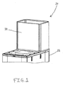
- Fig. 1 shows exhaust duct 30 installed on the top of server cabinet 32 in its lowest position
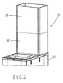
- Fig. 2 shows exhaust duct 30 in a fully extended position
- Exhaust duct 30 includes outer duct section 34 and inner duct section 36.
- outer duct section 34 is larger than inner duct section 36.
- FIG. 3 shows the formed pieces of outer duct section 34.
- Outer duct section 34 comprises a first portion 38 and a second portion 40.
- First portion 38 has top flanges 42, side flanges 44 and four mating loop flanges 46.
- Top flanges 42 may include a foam gasket seal that will press against the exhaust air plenum to ensure that hot air is evacuated from server cabinet 32 and channeled into the exhaust air plenum.
- Side flanges 44 overlaps side flanges 48 on second portion 40 to allow first and second portions 38, 40 to be spot-welded or riveted together.
- Inner duct section 36 has a similar two-piece construction.
- outer duct section 34 includes a mating loop flange 46 having a first aperture 50 and a second aperture 52.
- second aperture 52 is larger than first aperture 50.
- Inner duct section 36 includes a mating loop flange 54 having a plurality of apertures 56.
- apertures 56 are the same size as first aperture 50 and smaller than second aperture 52.
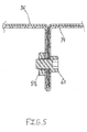
- First aperture 50 is aligned with one of apertures 56 and a nut 58 and bolt 60 secure outer duct section 34 to inner duct section 36, as shown in Fig. 5 .
- second aperture 52 is aligned with a different one of apertures 56 and a nut 62, bolt 64 and two paint piercing washers 66, 68 secure outer duct section 34 to inner duct section 36, as well as ground the duct sections together.
- First washer 66 bites into outer duct section 34 and second washer 68 bites, into inner duct section 36, as shown in Fig. 6 .
- an installer begins with exhaust duct 30 in its lowest position, as shown in Fig, 1 .
- the installer raises outer duct section 34 up to the exhaust air plenum, aligns first aperture 50 with one of apertures 56 and installs bolt 60 to secure outer duct section 34 in place.
- Nut 58 is installed and tightened to secure the connection.
- bolt 64, first washer 66, second washer 68 and nut 62 are installed to ground outer duct section 34 to inner duct section 36.
- exhaust duct 30 may be in a partially extended position or the fully extended position shown in Fig. 2 .
- Figs. 7-12 illustrate an adjustable vertical exhaust duct 130 which is mounted on server cabinet 132 in a data center room. Exhaust duct 130 will channel the hot air from server cabinet 132. into the exhaust air plenum of the data center room. Server cabinets 132 and the exhaust air plenums come in different heights, potentially leaving a variable gap between the top of server cabinets 132 and the plenums. Exhaust duct 130 can accommodate these varying heights.
- Fig. 7 shows exhaust duct 130 installed on the top of server cabinet 132 in its lowest position
- Fig. 8 shows exhaust duct 130 in a fully extended position.
- Exhaust duct 130 includes outer duct section 134 and inner duct section 136.
- outer duct section 134 is larger than inner duct section 136.
- outer duct section 134 includes locking block 138 bolted near the top edge of outer duct section 134.
- Locking block 138 comprises pawl 140 having a plurality of teeth 142, spring 144 and slot 146 for receiving an adjustment rod.
- pawl 140 is steel.
- inner duct section 136 has top flanges 148 that may include a foam gasket seal that will press against the exhaust air plenum to ensure that hot air is evacuated from server cabinet 132 and channeled into the exhaust air plenum.
- Inner duct section 136 also has a channel 150 including spacer 152, adjustment bar 154 and nut 156.
- adjustment bar 154 is aluminum.
- locking block 138 is assembled onto adjustment bar 154.
- Fig. 12 shows adjustment bar 154 attached to inner duct section 136 with stud 158 and nut 160.
- an installer begins with exhaust duct 130 in its lowest position, as shown in Fig. 7 .
- the installer raises inner duct section 136 up to the exhaust air plenum, and inner duct section 136 is automatically locked in place against the exhaust air plenum.
- pawl 140 is spring-loaded against adjustment bar 154 and tecth 142 bite into adjustment bar 154 to prevent adjustment bar 154 from slipping downward during the adjustment of inner duct section 136.
- exhaust duct 130 may be in a partially extended position or the fully extended position shown in Fig. 8 .
- the installers need to push down on each of four pawls 140.
- Figs. 13-16 illustrate an adjustable vertical exhaust duct 230 which is mounted on server cabinet 232 in a data center room. Exhaust duct 230 will channel the hot air from server cabinet 232 into the exhaust air plenum of the data center room. Server cabinets 232 and the exhaust air plenums come in different heights, potentially leaving a variable gap between the top of server cabinets 232 and the plenums. Exhaust duct 230 can accommodate these varying heights.
- Fig, 13 shows exhaust duct 230 installed on the top of server cabinet 232 in its lowest position
- Fig. 14 shows exhaust duct 230 in a fully extended position.
- Exhaust duct 230 includes outer duct section 234 and inner duct section 236.
- outer duct section 234 is larger than inner duct section 236.
- outer duct section 234 includes locking block 238 and set screw 240.
- Locking block 238 can sit on the top edge of outer duct section 234 or locking block 238 can be attached to outer duct section 234 bay known attachment means.
- Locking block 238 has slot 242 for receiving an adjustment bar.
- Inner duct section 236 may include top flanges and a foam gasket seal that will press against the exhaust air plenum to ensure that hot air is evacuated from server cabinet 232 and channeled into the exhaust air plenum. As best seen in Fig. 15 , inner duct section 236 also includes channel 244 having adjustment bar 246.
- an installer begins with exhaust duct 230 in its lowest position, as shown in Fig. 13 .
- the installer raises inner duct section 236 up to the exhaust air plenum, holds inner duct section 236 in place and tightens the four set screws 240 to prevent inner duct section 236 from sliding back down inside outer duct section 234.
- exhaust duct 230 may be in a partially extended position or the fully extended position shown in Fig. 14 .
- the installers need to hold onto inner duct section 236 and loosen four set screws 240.
- Inner duct section 236 is now free to move down.
- Figs. 17-21 illustrate an adjustable vertical exhaust duct 330 which is mounted on server cabinet 332 in a data center room. Exhaust duct 330 will channel the hot air from server cabinet 332 into the exhaust air plenum of the data center room. Server cabinets 332 and the exhaust air plenums come in different heights, potentially leaving a variable gap between the top of server cabinets 332 and the plenums. Exhaust duct 330 can accommodate these varying heights.
- Fig. 17 shows exhaust duct 330 installed on the top of server cabinet 332 in its lowest position
- Fig. 18 shows exhaust duct 330 in a fully extended position.
- Exhaust duct 330 includes outer duct section 334 and inner duct section 336.
- outer duct section 334 is larger than inner duct section 336.
- outer duct section 334 includes locking block 338 bolted near the bottom edge of outer duct section 334.
- Locking block 338 comprises a slot 340 for receiving an adjustment rod, lock block tab 342, bar lock 343 having bar lock tab 344 and spring 346.
- Inner duct section 336 may have top flanges and a foam gasket seal that will press against the exhaust air plenum to ensure that hot air is evacuated from server cabinet 332 and channeled into the exhaust air plenum.
- Inner duct section 336 also has a channel 348, and channel 348 includes mounting bracket 350 having slot 352 for receiving adjustment bar 354 and roll pin 356.
- Adjustment bar 354 is attached to inner duct section 336 through mounting bracket 350 and retained by roll pin 356.
- adjustment bar 354 has teeth 358 on one side for engaging bar lock 343.
- an installer begins with exhaust duct 330 in its lowest position, as shown in Fig. 17 .
- the installer raises outer duct section 334 up to the exhaust air plenum, and outer duct section 334 is automatically locked in place against the exhaust air plenum.
- compression spring 346 forces bar lock 343 at an angle with respect to adjustment bar 354 causing the edge of the slot opening in bar lock 343 to bite into teeth 358 of adjustment bar 354, thus locking outer duct section 334 at any point along adjustment bar 354.
- exhaust duct 330 may be in a partially extended position or the fully extended position shown in Fig. 18 .
- the installers need to squeeze bar lock tabs 344 against lock block tabs 342 that are located on all four corners of outer duct section 334. Outer duct section 334 is then free to move down.
- Figs. 22-27 illustrate an adjustable vertical exhaust duct 430 which is mounted on a server cabinet in a data center room. Exhaust duct 430 will channel the hot air from the server cabinet into the exhaust air plenum of the data center room.
- the server cabinets and the exhaust air plenums come in different heights, potentially leaving a variable gap between the top of the server cabinets and the plenums. Exhaust duct 430 can accommodate these varying heights.
- Fig. 22 shows exhaust duct 430 in its lowest position
- Fig. 23 shows exhaust duct 430 in a fully extended position.
- exhaust duct 430 is preferably 34 inches high.
- exhaust duct 430 is preferably 60 inches high.
- Exhaust duct 430 includes outer duct section 434 and inner duct section 436.
- outer duct section 434 is larger than inner duct section 436.
- Fig. 24 shows the formed pieces of outer duct section 434.
- Outer duct section 434 comprises two end panels 438, two side panels 440 and duct bottom 442.
- end panels 438 and side panels 440 hook together at the corners using open hems on each piece and are held together with threaded fasteners.
- the end panel and side panel assembly is attached to duct bottom 442.
- Fig. 26 shows the formed pieces of inner duct section 436.
- Inner duct section 436 comprises two end panels 444, two side panels 446 and top flanges 448. End panels 444 and side panels 446 hook together at the corners using open hems on each piece and are held together with threaded fasteners.
- Top flanges 448 are attached to the top edges of inner duct section 436. Top flanges 448 may include a foam gasket seal that will press against the exhaust air plenum to ensure that hot air is evacuated from the server cabinet and channeled into the exhaust air plenum.
- Outer duct section 434 includes a plurality of slots 450.
- each slot 450 is identical.
- Inner duct section 436 includes a plurality of apertures having a plurality of nuts 452.
- each aperture is identical and each nut 452 is a PEM nut.
- slots 450 in outer duct section 434 align with nuts 452 on inner duct section 436 and screws hold outer and inner duct sections 434, 436 together at the desired height.
- the screws may include paint piercing washers to ground outer and inner duct sections 434, 436 together.
- outer duct section 434 overlaps inner duct section 436 to cover each slot 450 and prevent air leakage.
- an installer begins with exhaust duct 430 in its lowest position, as shown in Fig. 22 .
- the installer raises inner duct section 436 up to the exhaust air plenum, aligns slots 450 in outer duct section 434 and nuts 452 on inner duct section 436, and installs screws to secure outer duct section 434 to inner duct section 436.
- exhaust duct 430 may be in a partially extended position or the fully extended position shown in Fig. 23 .
- Figs. 28-31 illustrate an adjustable vertical exhaust duct 530 which is mounted on server cabinet 532 in a data center room. Exhaust duct 530 will channel the hot air from server cabinet 532 into the exhaust air plenum of the data center room. Server cabinets 532 and the exhaust air plenums come in different heights, potentially leaving a gap between the top of server cabinets 532 and the plenums. Exhaust duct 530 can accommodate these varying heights.
- Fig. 28 shows exhaust duct 530 installed on the top of server cabinet 532 in its fully extended position.
- exhaust duct 530 includes lower duet section 534 and upper duct section 536.
- lower duct section 534 is larger than upper duct section 536.
- Exhaust duct 530 is similar to exhaust duct 30 shown in Figs. 1-6 , except exhaust duct 530 has recessed mating loop flanges 538, 540 that create an adjustment channel recessed from the front face of lower duct section 534 and upper duct section 536 (see Fig. 30 ).
- lower duct section 534 includes mating loop flange 538 having two apertures 542.
- Upper duet section 536 instricts mating loop Hange 540 having a plurality of apertures 544.
- apertures 542 are the same size as apertures 544.
- One of apertures 542 is aligned with one of apertures 544 and a fastener, such as a screw, bolt or clevis, secures lower duct section 534 to upper duct section 536.
- an installer begins with exhaust duct 530 in its lowest position.
- the installer raises upper duct section 536 up to the exhaust air plenum, aligns one of apertures 542 with one of apertures 544 and installs the fastener to secure upper duct section 536 in place.
- exhaust duct 530 may be in a partially extended position or the fully extended position shown in Figs. 28 and 29 .
- Figs. 32-35 illustrate an adjustable vertical exhaust duct 630 which is mounted on a server cabinet in a data center room. Exhaust duct 630 will channel the hot air from the server cabinet into the exhaust air plenum of the data center room.
- the server cabinets and the exhaust air plenums come in different heights, potentially leaving a gap between the top of the server cabinets and the plenums. Exhaust duct 630 can accommodate these varying heights.
- upper duct section 636 has top flanges 638 that may include a foam gasket that will press against the exhaust air plenum to ensure that hot air is evacuated from the server cabinet and channeled into the exhaust air plenum.
- Exhaust duct 630 includes lower duct section 634 and upper duct section 636. Preferably, lower duct section 634 is larger than upper duct section 636. Exhaust duct 630 is similar to exhaust duct 130 shown in Figs. 7-12 , except exhaust duct 630 has pawl lockout 640. Pawl lockout 640 allows installers to lockout pawl 642 from engaging adjustment bar 644, freeing upper duet section 636 so it can be lowered. By deactivating pawl lockout 640, pawl 642 will automatically engage adjustment bar 644 and lock the location of exhaust duct 630. Preferably, pawl 642 is steel and adjustment bar 644 is aluminum.
- an installer begins with exhaust duct 630 in its lowest position.
- the installer raises upper duct section 636 up to the exhaust air plenum, and upper duct section 636 is locked in place against the exhaust air plenum.
- Fig. 32 shows pawl lockout 640 in the disengaged position, allowing pawl 642 to engage adjustment bar 644 and lock exhaust duct 630 in place.
- pawl 642 is spring-loaded against adjustment bar 644 and teeth 646 bite into adjustment bar 644.
- pawl lockout 640 is positioned below stop screw 648 (see Fig. 32 ).
- exhaust duct 630 may be in a partially extended position or a fully extended position.
- the installer rotates pawl lockout 640 one hundred eighty degrees from its position in Fig. 32 to lockout pawl 642 from engaging adjustment bar 644 ( Fig. 35 ).
- pawl lockout 640 is engaged with pawl 642, freeing upper duct section 636 so it can be lowered. In the engaged position, pawl lockout 640 is positioned above stop screw 648.
Landscapes
- Engineering & Computer Science (AREA)
- Computer Hardware Design (AREA)
- General Engineering & Computer Science (AREA)
- Physics & Mathematics (AREA)
- Thermal Sciences (AREA)
- Microelectronics & Electronic Packaging (AREA)
- Ventilation (AREA)
- Cooling Or The Like Of Electrical Apparatus (AREA)
- Duct Arrangements (AREA)
Description
- The present invention relates to an adjustable vertical exhaust duct and, in particular, the invention relates to an adjustable vertical exhaust duct to be mounted on a server cabinet in a data center room.
- Currently available vertical exhaust ducts channel hot air form the server cabinet into the exhaust air plenum of the data center room. However, the server cabinets and the data center exhaust air plenums come in different heights, potentially leaving a variable gap between the top of the server cabinets and the plenum.
- Therefore, there is a need for an adjustable vertical exhaust duct that will accommodate varying heights between server cabinets and exhaust air plenums to ensure that hot air is evacuated from the server cabinet and channeled into the exhaust air plenum.
-
US Patent Application no. 2007/0064389 discloses an electronic equipment enclosure comprising a frame structure formed from a plurality of support posts and at least partially enclosed by a plurality of panels. - Certain embodiments of the present invention provide a vertical exhaust duct for an electronic equipment enclosure. The vertical exhaust duct includes an inner duct section and an outer duct section. The inner duct section nests within the outer duct section and telescopes to adjust the height of the vertical exhaust duct.
- In certain embodiments of the present invention, the outer duct section includes at least one elongated opening for securing the vertical exhaust duct at a desired height.
- In certain embodiments of the present invention, the outer duct section includes at least one pawl for securing the vertical exhaust duct at a desired height.
-
-
Fig. 1 is a top perspective view of an adjustable vertical exhaust duct in accordance with the present invention, wherein the exhaust duct is installed on the top of a server cabinet in the lowest position; -
Fig. 2 is a top perspective view of the adjustable vertical exhaust duct ofFig. 1 , wherein the exhaust duct is installed on the top of the server cabinet in a fully extended position; -
Fig. 3 is a top perspective view of two halves of an outer duct section ofFig. 2 , before they are assembled together; -
Fig. 4 is a detailed view of one of the locking systems and the grounding system of the adjustable vertical exhaust duct ofFig. 2 , wherein four identical nut and bolt locking systems secure the outer duct section to an inner duct section; -
Fig. 5 is a cross-sectional view of the locking system ofFig. 4 , wherein the locking system secures the outer duct section to the inner duct section; -
Fig. 6 is a cross-sectional view of the grounding system ofFig. 4 , wherein the grounding system grounds the outer duct section to the inner duct section; -
Fig. 7 is a top perspective view of an adjustable vertical exhaust duct in accordance with another embodiment of the present invention, wherein the exhaust duct is installed on the top of a server cabinet in the lowest position; -
Fig. 8 is a top perspective view of the adjustable vertical exhaust duct ofFig. 7 , wherein the exhaust duct is installed on the top of the server cabinet in a fully extended position; -
Fig. 9 is a detailed view of one of the locking systems of the adjustable vertical exhaust duct ofFig. 7 , wherein four identical pawl locking systems secure an outer duct section to an inner duct section; -
Fig. 10 is a top side perspective view of the outer duct section ofFig. 9 ; -
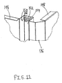
Fig. 11 is a top front perspective view of the inner duct section ofFig. 9 ; - Fig. F2 is a cross-sectional view of the locking system of
Fig. 9 , wherein the locking system secures the outer duct section to the inner duct section; -
Fig. 13 is a top perspective view of an adjustable vertical exhaust duct in accordance with another embodiment of the present invention, wherein the exhaust duct is installed on the top of a server cabinet in the lowest position; -
Fig. 14 is a top perspective view of the adjustable vertical exhaust duct ofFig. 13 , wherein the exhaust duct is installed on the top of the server cabinet in a fully extended position; -
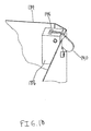
Fig. 15 is a detailed view of one of the locking systems of the adjustable vertical exhaust duct ofFig. 14 , wherein four identical locking systems support the inner duct section on the outer duct section; -
Fig. 16 is a cross-sectional view of the locking system ofFig. 15 ; -
Fig. 17 is a top perspective view of an adjustable vertical exhaust duct in accordance with another embodiment of the present invention, wherein the exhaust duct is installed on the top of a server cabinet in the lowest position; -
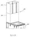
Fig. 18 is a top perspective view of the adjustable vertical exhaust duct ofFig. 17 , wherein the exhaust duct is installed on the top of the server cabinet, in a fully extended position; -
Fig. 19 is a detailed view of one of the locking systems of the adjustable vertical exhaust duct ofFig. 18 , wherein four identical bar clamp locking systems secure an outer duct section to an inner duct section; -
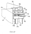
Fig. 20 is a detailed view of the adjustable vertical exhaust duct ofFig. 19 , wherein the outer duct section has been removed; -
Fig. 21 is a cross-sectional view of the locking system ofFig. 20 , wherein the locking system secures the outer duct section to the inner duct section; -
Fig. 22 is a top perspective view of an adjustable vertical exhaust duct in accordance with another embodiment of the present invention, wherein the exhaust duct is shown in the lowest position; -
Fig. 23 is a top perspective view of the adjustable vertical exhaust duct ofFig. 22 , wherein the exhaust duct is shown in a fully extended position; -
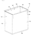
Fig. 24 is a top perspective view of the components of an outer duct section ofFig. 23 , before they are assembled together; -
Fig. 25 is a detailed view of a portion of the outer duct section ofFig. 24 after assembly; -
Fig. 26 is a top perspective view of the components of an inner duct section ofFig. 23 , partially assembled; -
Fig. 27 is a detailed view of one of the locking systems of the adjustable vertical exhaust duct. ofFig. 23 , wherein four identical nut, screw and slot locking systems secure the outer duct section to the inner duct section; -
Fig. 28 is a top perspective view of an adjustable vertical exhaust duct in accordance with another embodiment of the present invention, wherein the exhaust duct is installed on the top of a server cabinet in a fully extended position; -
Fig. 29 is a top perspective view of the adjustable vertical exhaust duct ofFig. 28 ; -
Fig. 30 is a detailed view of section A ofFig. 29 ; -
Fig. 31 is a detailed view of one of the locking systems of the adjustable vertical exhaust duct ofFig. 28 , wherein four identical locking systems secure a lower duct section to an upper duct section; -
Fig. 32 is a detailed view of one of the lockout systems of an adjustable vertical exhaust duct in accordance with another embodiment of the present invention, wherein a pawl lockout is in a disengaged position with a pawl; -
Fig. 33 is a cross-sectional view of the lockout system ofFig. 32 ; -
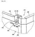
Fig. 34 is a detailed view of one of the lockout systems of the adjustable vertical exhaust duct ofFig. 32 , wherein the pawl lockout is engaged with the pawl; and -
Fig. 35 is a cross-sectional view of the lockout system ofFig. 34 , wherein the lockout system is engaged and the pawl is disengaged. -
Figs. 1-6 illustrate an adjustablevertical exhaust duct 30 which is mounted onserver cabinet 32 in a data center room.Exhaust duct 30 will channel the hot air fromserver cabinet 32 into the exhaust air plenum of the data center room.Server cabinets 32 and the exhaust air plenums come in different heights, potentially leaving a variable gap between the top ofserver cabinets 32 and the plenums.Exhaust duct 30 can accommodate these varying heights. -
Fig. 1 showsexhaust duct 30 installed on the top ofserver cabinet 32 in its lowest position, andFig. 2 showsexhaust duct 30 in a fully extended position.Exhaust duct 30 includesouter duct section 34 andinner duct section 36. Preferably,outer duct section 34 is larger thaninner duct section 36. -
Fig. 3 shows the formed pieces ofouter duct section 34.Outer duct section 34 comprises a first portion 38 and a second portion 40. First portion 38 has top flanges 42,side flanges 44 and fourmating loop flanges 46. Top flanges 42 may include a foam gasket seal that will press against the exhaust air plenum to ensure that hot air is evacuated fromserver cabinet 32 and channeled into the exhaust air plenum.Side flanges 44 overlaps side flanges 48 on second portion 40 to allow first and second portions 38, 40 to be spot-welded or riveted together.Inner duct section 36 has a similar two-piece construction. - As shown in
Fig. 4 ,outer duct section 34 includes amating loop flange 46 having afirst aperture 50 and asecond aperture 52. Preferably,second aperture 52 is larger thanfirst aperture 50.Inner duct section 36 includes a mating loop flange 54 having a plurality of apertures 56. Preferably, apertures 56 are the same size asfirst aperture 50 and smaller thansecond aperture 52.First aperture 50 is aligned with one of apertures 56 and anut 58 andbolt 60 secureouter duct section 34 toinner duct section 36, as shown inFig. 5 . Similarly,second aperture 52 is aligned with a different one of apertures 56 and a nut 62,bolt 64 and twopaint piercing washers 66, 68 secureouter duct section 34 toinner duct section 36, as well as ground the duct sections together.First washer 66 bites intoouter duct section 34 and second washer 68 bites, intoinner duct section 36, as shown inFig. 6 . - In operation, an installer begins with
exhaust duct 30 in its lowest position, as shown inFig, 1 . The installer raisesouter duct section 34 up to the exhaust air plenum, alignsfirst aperture 50 with one of apertures 56 and installsbolt 60 to secureouter duct section 34 in place.Nut 58 is installed and tightened to secure the connection. Once the height has been set,bolt 64,first washer 66, second washer 68 and nut 62 are installed to groundouter duct section 34 toinner duct section 36. After installation,exhaust duct 30 may be in a partially extended position or the fully extended position shown inFig. 2 . -
Figs. 7-12 illustrate an adjustable vertical exhaust duct 130 which is mounted onserver cabinet 132 in a data center room. Exhaust duct 130 will channel the hot air fromserver cabinet 132. into the exhaust air plenum of the data center room.Server cabinets 132 and the exhaust air plenums come in different heights, potentially leaving a variable gap between the top ofserver cabinets 132 and the plenums. Exhaust duct 130 can accommodate these varying heights. -
Fig. 7 shows exhaust duct 130 installed on the top ofserver cabinet 132 in its lowest position, andFig. 8 shows exhaust duct 130 in a fully extended position. Exhaust duct 130 includesouter duct section 134 andinner duct section 136. Preferably,outer duct section 134 is larger thaninner duct section 136. - As shown in
Figs. 10 and12 ,outer duct section 134 includes lockingblock 138 bolted near the top edge ofouter duct section 134. Lockingblock 138 comprisespawl 140 having a plurality of teeth 142, spring 144 and slot 146 for receiving an adjustment rod. Preferably,pawl 140 is steel. - As best seen in
Figs. 9 and11 ,inner duct section 136 hastop flanges 148 that may include a foam gasket seal that will press against the exhaust air plenum to ensure that hot air is evacuated fromserver cabinet 132 and channeled into the exhaust air plenum.Inner duct section 136 also has achannel 150 including spacer 152,adjustment bar 154 andnut 156. Preferably,adjustment bar 154 is aluminum. Before spacer 152 andnut 156 are installed, lockingblock 138 is assembled ontoadjustment bar 154.Fig. 12 showsadjustment bar 154 attached toinner duct section 136 withstud 158 andnut 160. - In operation, an installer begins with exhaust duct 130 in its lowest position, as shown in
Fig. 7 . The installer raisesinner duct section 136 up to the exhaust air plenum, andinner duct section 136 is automatically locked in place against the exhaust air plenum. As shown inFig, 12 ,pawl 140 is spring-loaded againstadjustment bar 154 and tecth 142 bite intoadjustment bar 154 to preventadjustment bar 154 from slipping downward during the adjustment ofinner duct section 136. After installation, exhaust duct 130 may be in a partially extended position or the fully extended position shown inFig. 8 . To release and lowerinner duct section 136, the installers need to push down on each of fourpawls 140. -
Figs. 13-16 illustrate an adjustablevertical exhaust duct 230 which is mounted onserver cabinet 232 in a data center room.Exhaust duct 230 will channel the hot air fromserver cabinet 232 into the exhaust air plenum of the data center room.Server cabinets 232 and the exhaust air plenums come in different heights, potentially leaving a variable gap between the top ofserver cabinets 232 and the plenums.Exhaust duct 230 can accommodate these varying heights. -
Fig, 13 showsexhaust duct 230 installed on the top ofserver cabinet 232 in its lowest position, andFig. 14 showsexhaust duct 230 in a fully extended position.Exhaust duct 230 includesouter duct section 234 andinner duct section 236. Preferably,outer duct section 234 is larger thaninner duct section 236. - As shown in
Fig. 15 and16 ,outer duct section 234 includes lockingblock 238 and setscrew 240. Lockingblock 238 can sit on the top edge ofouter duct section 234 or lockingblock 238 can be attached toouter duct section 234 bay known attachment means. Lockingblock 238 has slot 242 for receiving an adjustment bar. -
Inner duct section 236 may include top flanges and a foam gasket seal that will press against the exhaust air plenum to ensure that hot air is evacuated fromserver cabinet 232 and channeled into the exhaust air plenum. As best seen inFig. 15 ,inner duct section 236 also includeschannel 244 havingadjustment bar 246. - In operation, an installer begins with
exhaust duct 230 in its lowest position, as shown inFig. 13 . The installer raisesinner duct section 236 up to the exhaust air plenum, holdsinner duct section 236 in place and tightens the four setscrews 240 to preventinner duct section 236 from sliding back down insideouter duct section 234. After installation,exhaust duct 230 may be in a partially extended position or the fully extended position shown inFig. 14 . To release and lowerinner duct section 236, the installers need to hold ontoinner duct section 236 and loosen four setscrews 240.Inner duct section 236 is now free to move down. -
Figs. 17-21 illustrate an adjustablevertical exhaust duct 330 which is mounted onserver cabinet 332 in a data center room.Exhaust duct 330 will channel the hot air fromserver cabinet 332 into the exhaust air plenum of the data center room.Server cabinets 332 and the exhaust air plenums come in different heights, potentially leaving a variable gap between the top ofserver cabinets 332 and the plenums.Exhaust duct 330 can accommodate these varying heights. -
Fig. 17 showsexhaust duct 330 installed on the top ofserver cabinet 332 in its lowest position, andFig. 18 showsexhaust duct 330 in a fully extended position.Exhaust duct 330 includesouter duct section 334 andinner duct section 336. Preferably,outer duct section 334 is larger thaninner duct section 336. - As shown in
Figs. 19 and20 ,outer duct section 334 includes lockingblock 338 bolted near the bottom edge ofouter duct section 334. Lockingblock 338 comprises aslot 340 for receiving an adjustment rod,lock block tab 342,bar lock 343 havingbar lock tab 344 andspring 346. -
Inner duct section 336 may have top flanges and a foam gasket seal that will press against the exhaust air plenum to ensure that hot air is evacuated fromserver cabinet 332 and channeled into the exhaust air plenum.Inner duct section 336 also has achannel 348, andchannel 348 includes mountingbracket 350 having slot 352 for receivingadjustment bar 354 androll pin 356.Adjustment bar 354 is attached toinner duct section 336 through mountingbracket 350 and retained byroll pin 356. Preferably,adjustment bar 354 hasteeth 358 on one side for engagingbar lock 343. - In operation, an installer begins with
exhaust duct 330 in its lowest position, as shown inFig. 17 . The installer raisesouter duct section 334 up to the exhaust air plenum, andouter duct section 334 is automatically locked in place against the exhaust air plenum. As shown inFig. 21 ,compression spring 346 forces barlock 343 at an angle with respect toadjustment bar 354 causing the edge of the slot opening inbar lock 343 to bite intoteeth 358 ofadjustment bar 354, thus lockingouter duct section 334 at any point alongadjustment bar 354. After installation,exhaust duct 330 may be in a partially extended position or the fully extended position shown inFig. 18 . To release and lowerouter duct section 334, the installers need to squeezebar lock tabs 344 againstlock block tabs 342 that are located on all four corners ofouter duct section 334.Outer duct section 334 is then free to move down. -
Figs. 22-27 illustrate an adjustablevertical exhaust duct 430 which is mounted on a server cabinet in a data center room.Exhaust duct 430 will channel the hot air from the server cabinet into the exhaust air plenum of the data center room. The server cabinets and the exhaust air plenums come in different heights, potentially leaving a variable gap between the top of the server cabinets and the plenums.Exhaust duct 430 can accommodate these varying heights. -
Fig. 22 showsexhaust duct 430 in its lowest position, andFig. 23 showsexhaust duct 430 in a fully extended position. In its lowest position,exhaust duct 430 is preferably 34 inches high. In the fully extended position,exhaust duct 430 is preferably 60 inches high.Exhaust duct 430 includesouter duct section 434 andinner duct section 436. Preferably,outer duct section 434 is larger thaninner duct section 436. -
Fig. 24 shows the formed pieces ofouter duct section 434.Outer duct section 434 comprises twoend panels 438, twoside panels 440 andduct bottom 442. As shown inFig. 25 ,end panels 438 andside panels 440 hook together at the corners using open hems on each piece and are held together with threaded fasteners. The end panel and side panel assembly is attached toduct bottom 442. -
Fig. 26 shows the formed pieces ofinner duct section 436.Inner duct section 436 comprises twoend panels 444, twoside panels 446 and top flanges 448.End panels 444 andside panels 446 hook together at the corners using open hems on each piece and are held together with threaded fasteners. Top flanges 448 are attached to the top edges ofinner duct section 436. Top flanges 448 may include a foam gasket seal that will press against the exhaust air plenum to ensure that hot air is evacuated from the server cabinet and channeled into the exhaust air plenum. -
Outer duct section 434 includes a plurality ofslots 450. Preferably, eachslot 450 is identical.Inner duct section 436 includes a plurality of apertures having a plurality of nuts 452. Preferably, each aperture is identical and eachnut 452 is a PEM nut. As shown inFig. 27 ,slots 450 inouter duct section 434 align withnuts 452 oninner duct section 436 and screws hold outer andinner duct sections inner duct sections outer duct section 434 overlapsinner duct section 436 to cover eachslot 450 and prevent air leakage. - In operation, an installer begins with
exhaust duct 430 in its lowest position, as shown inFig. 22 . The installer raisesinner duct section 436 up to the exhaust air plenum, alignsslots 450 inouter duct section 434 andnuts 452 oninner duct section 436, and installs screws to secureouter duct section 434 toinner duct section 436. After installation,exhaust duct 430 may be in a partially extended position or the fully extended position shown inFig. 23 . -
Figs. 28-31 illustrate an adjustablevertical exhaust duct 530 which is mounted onserver cabinet 532 in a data center room.Exhaust duct 530 will channel the hot air fromserver cabinet 532 into the exhaust air plenum of the data center room.Server cabinets 532 and the exhaust air plenums come in different heights, potentially leaving a gap between the top ofserver cabinets 532 and the plenums.Exhaust duct 530 can accommodate these varying heights. -
Fig. 28 showsexhaust duct 530 installed on the top ofserver cabinet 532 in its fully extended position. As best seen inFig. 29 ,exhaust duct 530 includeslower duet section 534 andupper duct section 536. Preferably,lower duct section 534 is larger thanupper duct section 536.Exhaust duct 530 is similar toexhaust duct 30 shown inFigs. 1-6 , exceptexhaust duct 530 has recessedmating loop flanges lower duct section 534 and upper duct section 536 (seeFig. 30 ). - As shown in
Fig. 31 ,lower duct section 534 includesmating loop flange 538 having twoapertures 542.Upper duet section 536 inchidesmating loop Hange 540 having a plurality ofapertures 544. Preferably,apertures 542 are the same size asapertures 544. One ofapertures 542 is aligned with one ofapertures 544 and a fastener, such as a screw, bolt or clevis, secureslower duct section 534 toupper duct section 536. - In operation, an installer begins with
exhaust duct 530 in its lowest position. The installer raisesupper duct section 536 up to the exhaust air plenum, aligns one ofapertures 542 with one ofapertures 544 and installs the fastener to secureupper duct section 536 in place. After installation,exhaust duct 530 may be in a partially extended position or the fully extended position shown inFigs. 28 and29 . -
Figs. 32-35 illustrate an adjustablevertical exhaust duct 630 which is mounted on a server cabinet in a data center room.Exhaust duct 630 will channel the hot air from the server cabinet into the exhaust air plenum of the data center room. The server cabinets and the exhaust air plenums come in different heights, potentially leaving a gap between the top of the server cabinets and the plenums.Exhaust duct 630 can accommodate these varying heights. As best seen inFigs. 32 and34 , upper duct section 636 hastop flanges 638 that may include a foam gasket that will press against the exhaust air plenum to ensure that hot air is evacuated from the server cabinet and channeled into the exhaust air plenum. -
Exhaust duct 630 includeslower duct section 634 and upper duct section 636. Preferably,lower duct section 634 is larger than upper duct section 636.Exhaust duct 630 is similar to exhaust duct 130 shown inFigs. 7-12 , exceptexhaust duct 630 haspawl lockout 640.Pawl lockout 640 allows installers tolockout pawl 642 from engagingadjustment bar 644, freeing upper duet section 636 so it can be lowered. By deactivatingpawl lockout 640,pawl 642 will automatically engageadjustment bar 644 and lock the location ofexhaust duct 630. Preferably,pawl 642 is steel andadjustment bar 644 is aluminum. - In operation, an installer begins with
exhaust duct 630 in its lowest position. The installer raises upper duct section 636 up to the exhaust air plenum, and upper duct section 636 is locked in place against the exhaust air plenum.Fig. 32 showspawl lockout 640 in the disengaged position, allowingpawl 642 to engageadjustment bar 644 and lockexhaust duct 630 in place. As shown inFig. 33 ,pawl 642 is spring-loaded againstadjustment bar 644 andteeth 646 bite intoadjustment bar 644. In the disengaged position,pawl lockout 640 is positioned below stop screw 648 (seeFig. 32 ). - After installation,
exhaust duct 630 may be in a partially extended position or a fully extended position. To release and lower upper duct section 636, the installer rotatespawl lockout 640 one hundred eighty degrees from its position inFig. 32 tolockout pawl 642 from engaging adjustment bar 644 (Fig. 35 ). As shown inFig. 34 ,pawl lockout 640 is engaged withpawl 642, freeing upper duct section 636 so it can be lowered. In the engaged position,pawl lockout 640 is positioned abovestop screw 648.
Claims (7)
- A vertical exhaust duct (30) for an electronic equipment enclosure, the vertical exhaust duct (30) comprising:an inner duct section (36) and an outer duct section (34),wherein the inner duct section (36) nests within the outer duct section (34) and telescopes to adjust the height of the vertical exhaust duct (30),characterised in that the outer duct section (34) includes at least one spring loaded pawl (140) that engages the inner duct section (36) for securing the vertical exhaust duct (30) at a desired height, wherein the pawl (140) allows the inner duct section (36) to expand and prevents the inner duct from retracting.
- The vertical exhaust duct (30) of claim 1, wherein the outer duct section (34) includes a pawl lockout for disengaging the pawl (140) from the inner duct section (36).
- The vertical exhaust duct (30) of claim 1, wherein the inner duct section (36) includes a channel (150) and a bar (154) disposed in the channel and spaced apart from the inner duct section (36).
- The vertical exhaust duct (30) of claim 3, wherein the pawl (140) engages the bar (154), and optionally wherein the pawl (140) is steel and the bar (154) is aluminum.
- The vertical exhaust duct (30) of claim 1, wherein the inner duct section (36) includes a top flange (148).
- The vertical exhaust duct (30) of claim 5, wherein the top flange (148) includes a seal.
- The vertical exhaust duct (30) of claim 1, further comprising a base for securing the outer duct section (34) to the electronic equipment enclosure.
Applications Claiming Priority (4)
| Application Number | Priority Date | Filing Date | Title |
|---|---|---|---|
| US16449909P | 2009-03-30 | 2009-03-30 | |
| US18693309P | 2009-06-15 | 2009-06-15 | |
| US12/731,877 US9210833B2 (en) | 2009-03-30 | 2010-03-25 | Adjustable vertical exhaust duct |
| PCT/US2010/028991 WO2010117699A1 (en) | 2009-03-30 | 2010-03-29 | Adjustable vertical exhaust duct |
Publications (2)
| Publication Number | Publication Date |
|---|---|
| EP2415335A1 EP2415335A1 (en) | 2012-02-08 |
| EP2415335B1 true EP2415335B1 (en) | 2014-03-05 |
Family
ID=42784863
Family Applications (1)
| Application Number | Title | Priority Date | Filing Date |
|---|---|---|---|
| EP10722462.8A Not-in-force EP2415335B1 (en) | 2009-03-30 | 2010-03-29 | Adjustable vertical exhaust duct |
Country Status (3)
| Country | Link |
|---|---|
| US (1) | US9210833B2 (en) |
| EP (1) | EP2415335B1 (en) |
| WO (1) | WO2010117699A1 (en) |
Families Citing this family (33)
| Publication number | Priority date | Publication date | Assignee | Title |
|---|---|---|---|---|
| US11259446B2 (en) | 2005-09-19 | 2022-02-22 | Chatsworth Products, Inc. | Vertical exhaust duct for electronic equipment enclosure |
| US8107238B2 (en) | 2005-09-19 | 2012-01-31 | Chatsworth Products, Inc. | Ducted exhaust equipment enclosure |
| US7804685B2 (en) | 2005-09-19 | 2010-09-28 | Chatsworth Products, Inc. | Ducted exhaust equipment enclosure |
| US7542287B2 (en) | 2005-09-19 | 2009-06-02 | Chatsworth Products, Inc. | Air diverter for directing air upwardly in an equipment enclosure |
| US11212928B2 (en) | 2005-09-19 | 2021-12-28 | Chatsworth Products, Inc. | Vertical exhaust duct for electronic equipment enclosure |
| US7839635B2 (en) | 2007-05-17 | 2010-11-23 | Chatsworth Products, Inc. | Exhaust air duct with adjustable filler panel assemblies |
| US9788455B1 (en) | 2007-06-14 | 2017-10-10 | Switch, Ltd. | Electronic equipment data center or co-location facility designs and methods of making and using the same |
| US9823715B1 (en) | 2007-06-14 | 2017-11-21 | Switch, Ltd. | Data center air handling unit including uninterruptable cooling fan with weighted rotor and method of using the same |
| US11452242B2 (en) | 2007-06-14 | 2022-09-20 | Switch, Ltd. | Air handling unit with a canopy thereover for use with a data center and method of using the same |
| US10028415B1 (en) | 2007-06-14 | 2018-07-17 | Switch, Ltd. | Electronic equipment data center and server co-location facility configurations and method of using the same |
| US9622389B1 (en) * | 2007-06-14 | 2017-04-11 | Switch, Ltd. | Electronic equipment data center and server co-location facility configurations and method of using the same |
| US8523643B1 (en) | 2007-06-14 | 2013-09-03 | Switch Communications Group LLC | Electronic equipment data center or co-location facility designs and methods of making and using the same |
| US10133320B2 (en) | 2008-02-14 | 2018-11-20 | Chatsworth Products, Inc. | Air directing device |
| US10371411B2 (en) * | 2009-10-22 | 2019-08-06 | Nortek Air Solutions, Llc | Ceiling system with integrated equipment support structure |
| US8628153B2 (en) * | 2010-05-13 | 2014-01-14 | Pandult Corp. | Aisle containment system |
| US8628158B2 (en) | 2010-05-13 | 2014-01-14 | Panduit Corp. | Aisle containment system |
| US8653363B2 (en) | 2010-06-01 | 2014-02-18 | Chatsworth Products, Inc. | Magnetic filler panel for use in airflow control system in electronic equipment enclosure |
| EP2429272A2 (en) | 2010-09-10 | 2012-03-14 | Chatsworth Products, Inc. | Cable pass-through panel for electronic equipment enclosure |
| US8901438B2 (en) | 2010-09-10 | 2014-12-02 | Chatsworth Products, Inc. | Electronic equipment cabinet structure |
| US8787023B2 (en) | 2010-09-10 | 2014-07-22 | Chatsworth Products, Inc. | Rail mounting clamp for electronic equipment enclosure |
| US9955616B2 (en) | 2010-11-08 | 2018-04-24 | Chatsworth Products, Inc. | Header panel assembly for preventing air circulation above electronic equipment enclosure |
| US9585266B2 (en) | 2010-11-08 | 2017-02-28 | Chatsworth Products, Inc. | Header panel assembly for preventing air circulation above electronic equipment enclosure |
| US9655259B2 (en) | 2011-12-09 | 2017-05-16 | Chatsworth Products, Inc. | Data processing equipment structure |
| US9313927B2 (en) | 2010-11-08 | 2016-04-12 | Chatsworth Products, Inc. | Header panel assembly for preventing air circulation above electronic equipment enclosure |
| CN103025136A (en) * | 2011-09-21 | 2013-04-03 | 鸿富锦精密工业(深圳)有限公司 | Electromagnetic shielding device and electronic device |
| US20140196394A1 (en) | 2013-01-11 | 2014-07-17 | Chatsworth Products, Inc. | Modular thermal isolation barrier for data processing equipment structure |
| US9198331B2 (en) | 2013-03-15 | 2015-11-24 | Switch, Ltd. | Data center facility design configuration |
| US10456878B2 (en) * | 2015-04-09 | 2019-10-29 | Ortronics, Inc. | Equipment cabinet and associated methods |
| US11622458B1 (en) | 2020-12-15 | 2023-04-04 | Chatsworth Products, Inc. | Brush port assembly and method for installing same |
| US11678456B1 (en) | 2020-12-15 | 2023-06-13 | Chatsworth Products, Inc. | Slidable mounting hardware for electronic equipment enclosure and method for installing same |
| US12048108B1 (en) | 2020-12-15 | 2024-07-23 | Chatsworth Products, Inc. | Caster attachment system using mating features |
| US11818860B1 (en) | 2020-12-15 | 2023-11-14 | Chatsworth Products, Inc. | Frame structure for electronic equipment enclosure |
| US11920392B1 (en) | 2021-02-02 | 2024-03-05 | Chatsworth Products, Inc. | Electrical bonding door hinges |
Family Cites Families (69)
| Publication number | Priority date | Publication date | Assignee | Title |
|---|---|---|---|---|
| US831429A (en) * | 1906-01-08 | 1906-09-18 | Daniel H Harrington | Attachment for stovepipes. |
| DE432098C (en) | 1918-05-03 | 1926-08-31 | Monnet & Cartier P | Process for carrying out catalytic reactions between gases or vapors |
| US3192306A (en) * | 1962-09-26 | 1965-06-29 | Philco Corp | Cooling wall structure for electronic equipment cabinet |
| US3842561A (en) * | 1973-06-14 | 1974-10-22 | M Wong | Adjustable ceiling strut |
| US3827342A (en) * | 1973-10-11 | 1974-08-06 | G Hughes | Air circulating device |
| US3930641A (en) * | 1974-09-12 | 1976-01-06 | Hawley Manufacturing Corporation | Furnace hood structure |
| DE2509487A1 (en) | 1975-03-05 | 1976-09-16 | Zdf | Forced-air cooled electronic equipment rack - involves individual air controls for different units to ensure adequate cooling for every unit |
| US4347782A (en) * | 1979-11-13 | 1982-09-07 | Enercon Systems, Incorporated | Telescopable winter/summer air recirculator |
| US4357860A (en) * | 1980-10-27 | 1982-11-09 | Mccormick-Morgan, Inc. | Telescoping conduit for pressurized air |
| US4522191A (en) * | 1984-01-11 | 1985-06-11 | The Coleman Company, Inc. | Non-pull apart telescoping roof jack assembly for furnace |
| US4543677A (en) * | 1984-04-09 | 1985-10-01 | Teledyne Industries, Inc. | Airtight telescoping rigid conduit |
| US4638563A (en) * | 1985-09-09 | 1987-01-27 | Buniff Egbert D N | Telescoping measuring stick with signal means |
| US4865013A (en) * | 1988-11-25 | 1989-09-12 | Nordyne, Inc. | Self-adjusting telescoping concentric flue assembly |
| WO1991006725A1 (en) | 1989-11-01 | 1991-05-16 | Peter John Warneford | Modular building systems |
| DE4127468C1 (en) * | 1991-08-20 | 1992-10-08 | Schroff Gmbh, 7541 Straubenhardt, De | |
| US5292282A (en) * | 1992-10-13 | 1994-03-08 | Callas Mike T | Air guard |
| US5511842A (en) * | 1993-10-06 | 1996-04-30 | Dillon; John A. | Security vehicle system |
| SE9304264L (en) * | 1993-12-22 | 1995-06-23 | Ericsson Telefon Ab L M | Method and apparatus for cooling in closed rooms |
| US5515655A (en) * | 1994-09-08 | 1996-05-14 | Sloan Enterprises, Inc. | Adjustable, telescoping structural support system |
| US5873556A (en) * | 1995-03-13 | 1999-02-23 | Reiker; Kenneth H. | Adjustable drop ceiling fixture support |
| JP3020695U (en) * | 1995-05-17 | 1996-02-06 | 耕三 福田 | Air circulation device |
| US5653631A (en) * | 1996-05-03 | 1997-08-05 | Builder's Best Inc. | Infinitely adjustable offset vent connector |
| US5997117A (en) * | 1997-06-06 | 1999-12-07 | Chatsworth Products, Inc. | Rack frame cabinet |
| US5791980A (en) * | 1997-07-03 | 1998-08-11 | Kramer, Jr.; Vance M. | Telescoping exhaust tube assembly |
| US5979854A (en) * | 1997-12-03 | 1999-11-09 | Lundgren; Curt | Strut apparatus for holding drywall panels and building materials in position |
| US6034873A (en) * | 1998-06-02 | 2000-03-07 | Ericsson Inc | System and method for separating air flows in a cooling system |
| US5995368A (en) * | 1998-10-20 | 1999-11-30 | Nortel Networks Corporation | Air flow distribution device for shelf-based circuit cards |
| US6554697B1 (en) * | 1998-12-30 | 2003-04-29 | Engineering Equipment And Services, Inc. | Computer cabinet design |
| JP2000286580A (en) | 1999-03-31 | 2000-10-13 | Toyo Electric Mfg Co Ltd | Electronic equipment cooling system |
| US6521835B1 (en) * | 1999-06-14 | 2003-02-18 | K. & M. Realty Trust | Cable raceway for bridges and like structures with channel members having multiple degrees of freedom |
| US6185098B1 (en) * | 2000-01-31 | 2001-02-06 | Chatsworth Products, Inc. | Co-location server cabinet |
| US6412292B2 (en) * | 2000-05-09 | 2002-07-02 | Toc Technology, Llc | Computer rack heat extraction device |
| US6574970B2 (en) * | 2000-02-18 | 2003-06-10 | Toc Technology, Llc | Computer room air flow method and apparatus |
| US6557357B2 (en) * | 2000-02-18 | 2003-05-06 | Toc Technology, Llc | Computer rack heat extraction device |
| US6383242B1 (en) * | 2000-03-07 | 2002-05-07 | Pacific Environmental Systems | Mobile enclosure unit |
| US6592448B1 (en) * | 2000-03-07 | 2003-07-15 | Contrapposto, Inc. | Computers with power exhaust systems |
| US6418010B1 (en) * | 2000-08-11 | 2002-07-09 | Gateway, Inc. | Convertible flat panel display hanging support |
| US6616524B2 (en) * | 2000-11-09 | 2003-09-09 | Gary A. Storck, Jr. | Raised floor air handling unit |
| US6575656B2 (en) * | 2001-05-24 | 2003-06-10 | Caravan Canopy International, Inc. | Pull pin assembly for canopy |
| US6672955B2 (en) * | 2001-09-07 | 2004-01-06 | International Business Machines Corporation | Air flow management system for an internet data center |
| JP3652634B2 (en) * | 2001-10-05 | 2005-05-25 | 本田技研工業株式会社 | Cooling structure for high piezoelectric parts |
| US6669552B1 (en) * | 2001-10-11 | 2003-12-30 | Ralph G. Beer | Telescopic ventline |
| US6766832B2 (en) * | 2001-12-20 | 2004-07-27 | Dimarco Benjamin M. | Transitional telescoping plenum apparatus |
| GB0207382D0 (en) * | 2002-03-28 | 2002-05-08 | Holland Heating Uk Ltd | Computer cabinet |
| WO2004011163A1 (en) * | 2002-07-26 | 2004-02-05 | Mintie Corporation | Environmental control unit |
| US6775997B2 (en) * | 2002-10-03 | 2004-08-17 | Hewlett-Packard Development Company, L.P. | Cooling of data centers |
| US7255640B2 (en) * | 2002-10-11 | 2007-08-14 | Liebert Corporation | Cable and air management adapter system for enclosures housing electronic equipment |
| US7752858B2 (en) * | 2002-11-25 | 2010-07-13 | American Power Conversion Corporation | Exhaust air removal system |
| US7500911B2 (en) * | 2002-11-25 | 2009-03-10 | American Power Conversion Corporation | Exhaust air removal system |
| US6867967B2 (en) * | 2002-12-16 | 2005-03-15 | International Business Machines Corporation | Method of constructing a multicomputer system |
| JP2004245327A (en) * | 2003-02-14 | 2004-09-02 | Jatco Ltd | Transmission hydraulic control unit for automatic transmission |
| US20050054282A1 (en) * | 2003-09-10 | 2005-03-10 | Adobeair, Inc. | Window evaporative cooler |
| US7372695B2 (en) * | 2004-05-07 | 2008-05-13 | Rackable Systems, Inc. | Directional fan assembly |
| US7137772B2 (en) * | 2004-05-18 | 2006-11-21 | Diani, Llc. | Retractable drum fan |
| DE202004016492U1 (en) * | 2004-10-25 | 2004-12-30 | Knürr AG | Equipment and network cabinet, especially server cabinet, has flow compatible inserts arranged to reduce flow resistance in feed air channel and/or waste air channel |
| US7236362B2 (en) * | 2004-11-18 | 2007-06-26 | Ncr Corporation | Minimization of cooling air preheat for maximum packaging density |
| KR100509570B1 (en) * | 2004-12-30 | 2005-08-22 | 주식회사 템피아 | Ceiling heat and cooling apparatus |
| US7452287B2 (en) * | 2005-03-18 | 2008-11-18 | Callaway Golf Company | Multiple material golf club head |
| US7836877B2 (en) * | 2005-05-02 | 2010-11-23 | Western Industries, Inc. | Adjustable downdraft ventilator |
| US8312873B2 (en) * | 2005-08-01 | 2012-11-20 | Western Industries, Inc. | Low depth telescoping downdraft ventilator |
| US20070064389A1 (en) * | 2005-09-19 | 2007-03-22 | Chatsworth Products, Inc. | Ducted exhaust equipment enclosure |
| US8107238B2 (en) * | 2005-09-19 | 2012-01-31 | Chatsworth Products, Inc. | Ducted exhaust equipment enclosure |
| US7804685B2 (en) * | 2005-09-19 | 2010-09-28 | Chatsworth Products, Inc. | Ducted exhaust equipment enclosure |
| US7542287B2 (en) * | 2005-09-19 | 2009-06-02 | Chatsworth Products, Inc. | Air diverter for directing air upwardly in an equipment enclosure |
| US7438638B2 (en) * | 2005-10-10 | 2008-10-21 | Chatsworth Products, Inc. | Ratio of open area to closed area in panels for electronic equipment enclosures |
| US7470176B2 (en) * | 2005-10-14 | 2008-12-30 | Flow Safe Inc | Converting existing prior art fume hoods into high performance low airflow stable vortex fume hoods |
| US7862410B2 (en) * | 2006-01-20 | 2011-01-04 | American Power Conversion Corporation | Air removal unit |
| US20070220846A1 (en) * | 2006-03-24 | 2007-09-27 | Jeremy Ray | Enclosed portable work station |
| US7839635B2 (en) * | 2007-05-17 | 2010-11-23 | Chatsworth Products, Inc. | Exhaust air duct with adjustable filler panel assemblies |
-
2010
- 2010-03-25 US US12/731,877 patent/US9210833B2/en active Active
- 2010-03-29 EP EP10722462.8A patent/EP2415335B1/en not_active Not-in-force
- 2010-03-29 WO PCT/US2010/028991 patent/WO2010117699A1/en not_active Ceased
Also Published As
| Publication number | Publication date |
|---|---|
| WO2010117699A1 (en) | 2010-10-14 |
| US20100248610A1 (en) | 2010-09-30 |
| EP2415335A1 (en) | 2012-02-08 |
| US9210833B2 (en) | 2015-12-08 |
Similar Documents
| Publication | Publication Date | Title |
|---|---|---|
| US9210833B2 (en) | Adjustable vertical exhaust duct | |
| US11889633B2 (en) | Header panel assembly for preventing air circulation above electronic equipment enclosure | |
| US8628153B2 (en) | Aisle containment system | |
| US9075290B1 (en) | Mounting bracket for surveillance cameras | |
| US20120181906A1 (en) | Aisle Containment System | |
| US8628154B2 (en) | Aisle containment system | |
| AU2019356905B2 (en) | System for mounting solar panels | |
| US9408465B2 (en) | Method and device for wall mounting flat panel monitor and storing associated audio/video components | |
| US9585266B2 (en) | Header panel assembly for preventing air circulation above electronic equipment enclosure | |
| US8632040B2 (en) | Low profile mounting of electronic devices | |
| US20090026338A1 (en) | Structural mounting for equipment on a rooftop | |
| US20180352955A1 (en) | Adjustable mount for a monitor | |
| US9322509B2 (en) | Equipment mounting bracket for steel truss | |
| JP2010286599A (en) | Display module and video display device | |
| US20220104619A1 (en) | Adjustible center post for multi-door enclosures | |
| CN111852826B (en) | Mount and equipment assembly | |
| CN220042753U (en) | Electrical cabinet top cover with adjustable protection level and convenient maintenance | |
| CN221457393U (en) | Charging pile | |
| CN204629987U (en) | A kind of filter installation frame and adopt the air-conditioning of this filter installation frame | |
| US9919866B2 (en) | Boltless containment | |
| TWM293045U (en) | Smoke prevention hanging board structure |
Legal Events
| Date | Code | Title | Description |
|---|---|---|---|
| PUAI | Public reference made under article 153(3) epc to a published international application that has entered the european phase |
Free format text: ORIGINAL CODE: 0009012 |
|
| 17P | Request for examination filed |
Effective date: 20111020 |
|
| AK | Designated contracting states |
Kind code of ref document: A1 Designated state(s): AT BE BG CH CY CZ DE DK EE ES FI FR GB GR HR HU IE IS IT LI LT LU LV MC MK MT NL NO PL PT RO SE SI SK SM TR |
|
| RIN1 | Information on inventor provided before grant (corrected) |
Inventor name: CAVENEY, JACK, E. Inventor name: HARTMAN, SCOTT, R. Inventor name: HIBNER, MAX, W. Inventor name: NICEWICZ, ANDRZEJ |
|
| DAX | Request for extension of the european patent (deleted) | ||
| GRAP | Despatch of communication of intention to grant a patent |
Free format text: ORIGINAL CODE: EPIDOSNIGR1 |
|
| INTG | Intention to grant announced |
Effective date: 20131018 |
|
| GRAS | Grant fee paid |
Free format text: ORIGINAL CODE: EPIDOSNIGR3 |
|
| GRAA | (expected) grant |
Free format text: ORIGINAL CODE: 0009210 |
|
| AK | Designated contracting states |
Kind code of ref document: B1 Designated state(s): AT BE BG CH CY CZ DE DK EE ES FI FR GB GR HR HU IE IS IT LI LT LU LV MC MK MT NL NO PL PT RO SE SI SK SM TR |
|
| REG | Reference to a national code |
Ref country code: GB Ref legal event code: FG4D |
|
| REG | Reference to a national code |
Ref country code: CH Ref legal event code: EP |
|
| REG | Reference to a national code |
Ref country code: AT Ref legal event code: REF Ref document number: 655607 Country of ref document: AT Kind code of ref document: T Effective date: 20140315 |
|
| REG | Reference to a national code |
Ref country code: IE Ref legal event code: FG4D |
|
| REG | Reference to a national code |
Ref country code: DE Ref legal event code: R096 Ref document number: 602010013958 Country of ref document: DE Effective date: 20140417 |
|
| REG | Reference to a national code |
Ref country code: AT Ref legal event code: MK05 Ref document number: 655607 Country of ref document: AT Kind code of ref document: T Effective date: 20140305 |
|
| REG | Reference to a national code |
Ref country code: NL Ref legal event code: VDEP Effective date: 20140305 |
|
| PG25 | Lapsed in a contracting state [announced via postgrant information from national office to epo] |
Ref country code: LT Free format text: LAPSE BECAUSE OF FAILURE TO SUBMIT A TRANSLATION OF THE DESCRIPTION OR TO PAY THE FEE WITHIN THE PRESCRIBED TIME-LIMIT Effective date: 20140305 Ref country code: NO Free format text: LAPSE BECAUSE OF FAILURE TO SUBMIT A TRANSLATION OF THE DESCRIPTION OR TO PAY THE FEE WITHIN THE PRESCRIBED TIME-LIMIT Effective date: 20140605 |
|
| REG | Reference to a national code |
Ref country code: LT Ref legal event code: MG4D |
|
| PG25 | Lapsed in a contracting state [announced via postgrant information from national office to epo] |
Ref country code: CY Free format text: LAPSE BECAUSE OF FAILURE TO SUBMIT A TRANSLATION OF THE DESCRIPTION OR TO PAY THE FEE WITHIN THE PRESCRIBED TIME-LIMIT Effective date: 20140305 Ref country code: AT Free format text: LAPSE BECAUSE OF FAILURE TO SUBMIT A TRANSLATION OF THE DESCRIPTION OR TO PAY THE FEE WITHIN THE PRESCRIBED TIME-LIMIT Effective date: 20140305 Ref country code: SE Free format text: LAPSE BECAUSE OF FAILURE TO SUBMIT A TRANSLATION OF THE DESCRIPTION OR TO PAY THE FEE WITHIN THE PRESCRIBED TIME-LIMIT Effective date: 20140305 Ref country code: FI Free format text: LAPSE BECAUSE OF FAILURE TO SUBMIT A TRANSLATION OF THE DESCRIPTION OR TO PAY THE FEE WITHIN THE PRESCRIBED TIME-LIMIT Effective date: 20140305 |
|
| PG25 | Lapsed in a contracting state [announced via postgrant information from national office to epo] |
Ref country code: LV Free format text: LAPSE BECAUSE OF FAILURE TO SUBMIT A TRANSLATION OF THE DESCRIPTION OR TO PAY THE FEE WITHIN THE PRESCRIBED TIME-LIMIT Effective date: 20140305 Ref country code: HR Free format text: LAPSE BECAUSE OF FAILURE TO SUBMIT A TRANSLATION OF THE DESCRIPTION OR TO PAY THE FEE WITHIN THE PRESCRIBED TIME-LIMIT Effective date: 20140305 |
|
| PG25 | Lapsed in a contracting state [announced via postgrant information from national office to epo] |
Ref country code: IS Free format text: LAPSE BECAUSE OF FAILURE TO SUBMIT A TRANSLATION OF THE DESCRIPTION OR TO PAY THE FEE WITHIN THE PRESCRIBED TIME-LIMIT Effective date: 20140705 Ref country code: EE Free format text: LAPSE BECAUSE OF FAILURE TO SUBMIT A TRANSLATION OF THE DESCRIPTION OR TO PAY THE FEE WITHIN THE PRESCRIBED TIME-LIMIT Effective date: 20140305 Ref country code: NL Free format text: LAPSE BECAUSE OF FAILURE TO SUBMIT A TRANSLATION OF THE DESCRIPTION OR TO PAY THE FEE WITHIN THE PRESCRIBED TIME-LIMIT Effective date: 20140305 Ref country code: CZ Free format text: LAPSE BECAUSE OF FAILURE TO SUBMIT A TRANSLATION OF THE DESCRIPTION OR TO PAY THE FEE WITHIN THE PRESCRIBED TIME-LIMIT Effective date: 20140305 Ref country code: BE Free format text: LAPSE BECAUSE OF FAILURE TO SUBMIT A TRANSLATION OF THE DESCRIPTION OR TO PAY THE FEE WITHIN THE PRESCRIBED TIME-LIMIT Effective date: 20140305 Ref country code: BG Free format text: LAPSE BECAUSE OF FAILURE TO SUBMIT A TRANSLATION OF THE DESCRIPTION OR TO PAY THE FEE WITHIN THE PRESCRIBED TIME-LIMIT Effective date: 20140605 Ref country code: RO Free format text: LAPSE BECAUSE OF FAILURE TO SUBMIT A TRANSLATION OF THE DESCRIPTION OR TO PAY THE FEE WITHIN THE PRESCRIBED TIME-LIMIT Effective date: 20140305 |
|
| REG | Reference to a national code |
Ref country code: CH Ref legal event code: PL |
|
| PG25 | Lapsed in a contracting state [announced via postgrant information from national office to epo] |
Ref country code: PL Free format text: LAPSE BECAUSE OF FAILURE TO SUBMIT A TRANSLATION OF THE DESCRIPTION OR TO PAY THE FEE WITHIN THE PRESCRIBED TIME-LIMIT Effective date: 20140305 Ref country code: ES Free format text: LAPSE BECAUSE OF FAILURE TO SUBMIT A TRANSLATION OF THE DESCRIPTION OR TO PAY THE FEE WITHIN THE PRESCRIBED TIME-LIMIT Effective date: 20140305 Ref country code: SK Free format text: LAPSE BECAUSE OF FAILURE TO SUBMIT A TRANSLATION OF THE DESCRIPTION OR TO PAY THE FEE WITHIN THE PRESCRIBED TIME-LIMIT Effective date: 20140305 |
|
| REG | Reference to a national code |
Ref country code: DE Ref legal event code: R097 Ref document number: 602010013958 Country of ref document: DE |
|
| PG25 | Lapsed in a contracting state [announced via postgrant information from national office to epo] |
Ref country code: PT Free format text: LAPSE BECAUSE OF FAILURE TO SUBMIT A TRANSLATION OF THE DESCRIPTION OR TO PAY THE FEE WITHIN THE PRESCRIBED TIME-LIMIT Effective date: 20140707 |
|
| REG | Reference to a national code |
Ref country code: IE Ref legal event code: MM4A |
|
| PLBE | No opposition filed within time limit |
Free format text: ORIGINAL CODE: 0009261 |
|
| STAA | Information on the status of an ep patent application or granted ep patent |
Free format text: STATUS: NO OPPOSITION FILED WITHIN TIME LIMIT |
|
| PG25 | Lapsed in a contracting state [announced via postgrant information from national office to epo] |
Ref country code: LI Free format text: LAPSE BECAUSE OF NON-PAYMENT OF DUE FEES Effective date: 20140331 Ref country code: IE Free format text: LAPSE BECAUSE OF NON-PAYMENT OF DUE FEES Effective date: 20140329 Ref country code: MC Free format text: LAPSE BECAUSE OF FAILURE TO SUBMIT A TRANSLATION OF THE DESCRIPTION OR TO PAY THE FEE WITHIN THE PRESCRIBED TIME-LIMIT Effective date: 20140305 Ref country code: DK Free format text: LAPSE BECAUSE OF FAILURE TO SUBMIT A TRANSLATION OF THE DESCRIPTION OR TO PAY THE FEE WITHIN THE PRESCRIBED TIME-LIMIT Effective date: 20140305 Ref country code: CH Free format text: LAPSE BECAUSE OF NON-PAYMENT OF DUE FEES Effective date: 20140331 |
|
| 26N | No opposition filed |
Effective date: 20141208 |
|
| REG | Reference to a national code |
Ref country code: DE Ref legal event code: R097 Ref document number: 602010013958 Country of ref document: DE Effective date: 20141208 |
|
| PG25 | Lapsed in a contracting state [announced via postgrant information from national office to epo] |
Ref country code: IT Free format text: LAPSE BECAUSE OF FAILURE TO SUBMIT A TRANSLATION OF THE DESCRIPTION OR TO PAY THE FEE WITHIN THE PRESCRIBED TIME-LIMIT Effective date: 20140305 |
|
| PG25 | Lapsed in a contracting state [announced via postgrant information from national office to epo] |
Ref country code: SI Free format text: LAPSE BECAUSE OF FAILURE TO SUBMIT A TRANSLATION OF THE DESCRIPTION OR TO PAY THE FEE WITHIN THE PRESCRIBED TIME-LIMIT Effective date: 20140305 |
|
| PG25 | Lapsed in a contracting state [announced via postgrant information from national office to epo] |
Ref country code: MT Free format text: LAPSE BECAUSE OF FAILURE TO SUBMIT A TRANSLATION OF THE DESCRIPTION OR TO PAY THE FEE WITHIN THE PRESCRIBED TIME-LIMIT Effective date: 20140305 |
|
| REG | Reference to a national code |
Ref country code: FR Ref legal event code: PLFP Year of fee payment: 7 |
|
| PG25 | Lapsed in a contracting state [announced via postgrant information from national office to epo] |
Ref country code: SM Free format text: LAPSE BECAUSE OF FAILURE TO SUBMIT A TRANSLATION OF THE DESCRIPTION OR TO PAY THE FEE WITHIN THE PRESCRIBED TIME-LIMIT Effective date: 20140305 |
|
| PG25 | Lapsed in a contracting state [announced via postgrant information from national office to epo] |
Ref country code: GR Free format text: LAPSE BECAUSE OF FAILURE TO SUBMIT A TRANSLATION OF THE DESCRIPTION OR TO PAY THE FEE WITHIN THE PRESCRIBED TIME-LIMIT Effective date: 20140606 |
|
| PG25 | Lapsed in a contracting state [announced via postgrant information from national office to epo] |
Ref country code: LU Free format text: LAPSE BECAUSE OF NON-PAYMENT OF DUE FEES Effective date: 20140329 Ref country code: TR Free format text: LAPSE BECAUSE OF FAILURE TO SUBMIT A TRANSLATION OF THE DESCRIPTION OR TO PAY THE FEE WITHIN THE PRESCRIBED TIME-LIMIT Effective date: 20140305 Ref country code: HU Free format text: LAPSE BECAUSE OF FAILURE TO SUBMIT A TRANSLATION OF THE DESCRIPTION OR TO PAY THE FEE WITHIN THE PRESCRIBED TIME-LIMIT; INVALID AB INITIO Effective date: 20100329 |
|
| REG | Reference to a national code |
Ref country code: FR Ref legal event code: PLFP Year of fee payment: 8 |
|
| REG | Reference to a national code |
Ref country code: FR Ref legal event code: PLFP Year of fee payment: 9 |
|
| PGFP | Annual fee paid to national office [announced via postgrant information from national office to epo] |
Ref country code: GB Payment date: 20180327 Year of fee payment: 9 |
|
| PGFP | Annual fee paid to national office [announced via postgrant information from national office to epo] |
Ref country code: FR Payment date: 20180326 Year of fee payment: 9 |
|
| PG25 | Lapsed in a contracting state [announced via postgrant information from national office to epo] |
Ref country code: MK Free format text: LAPSE BECAUSE OF FAILURE TO SUBMIT A TRANSLATION OF THE DESCRIPTION OR TO PAY THE FEE WITHIN THE PRESCRIBED TIME-LIMIT Effective date: 20140305 |
|
| PGFP | Annual fee paid to national office [announced via postgrant information from national office to epo] |
Ref country code: DE Payment date: 20180328 Year of fee payment: 9 |
|
| REG | Reference to a national code |
Ref country code: DE Ref legal event code: R119 Ref document number: 602010013958 Country of ref document: DE |
|
| GBPC | Gb: european patent ceased through non-payment of renewal fee |
Effective date: 20190329 |
|
| PG25 | Lapsed in a contracting state [announced via postgrant information from national office to epo] |
Ref country code: DE Free format text: LAPSE BECAUSE OF NON-PAYMENT OF DUE FEES Effective date: 20191001 Ref country code: GB Free format text: LAPSE BECAUSE OF NON-PAYMENT OF DUE FEES Effective date: 20190329 |
|
| PG25 | Lapsed in a contracting state [announced via postgrant information from national office to epo] |
Ref country code: FR Free format text: LAPSE BECAUSE OF NON-PAYMENT OF DUE FEES Effective date: 20190331 |