EP2414988B1 - Auto-exposure for multi-imager barcode reader - Google Patents
Auto-exposure for multi-imager barcode reader Download PDFInfo
- Publication number
- EP2414988B1 EP2414988B1 EP10726689.2A EP10726689A EP2414988B1 EP 2414988 B1 EP2414988 B1 EP 2414988B1 EP 10726689 A EP10726689 A EP 10726689A EP 2414988 B1 EP2414988 B1 EP 2414988B1
- Authority
- EP
- European Patent Office
- Prior art keywords
- view
- cameras
- camera
- light
- field
- Prior art date
- Legal status (The legal status is an assumption and is not a legal conclusion. Google has not performed a legal analysis and makes no representation as to the accuracy of the status listed.)
- Active
Links
Images



Classifications
-
- G—PHYSICS
- G06—COMPUTING OR CALCULATING; COUNTING
- G06K—GRAPHICAL DATA READING; PRESENTATION OF DATA; RECORD CARRIERS; HANDLING RECORD CARRIERS
- G06K7/00—Methods or arrangements for sensing record carriers, e.g. for reading patterns
- G06K7/10—Methods or arrangements for sensing record carriers, e.g. for reading patterns by electromagnetic radiation, e.g. optical sensing; by corpuscular radiation
- G06K7/10544—Methods or arrangements for sensing record carriers, e.g. for reading patterns by electromagnetic radiation, e.g. optical sensing; by corpuscular radiation by scanning of the records by radiation in the optical part of the electromagnetic spectrum
- G06K7/10712—Fixed beam scanning
- G06K7/10722—Photodetector array or CCD scanning
-
- G—PHYSICS
- G06—COMPUTING OR CALCULATING; COUNTING
- G06K—GRAPHICAL DATA READING; PRESENTATION OF DATA; RECORD CARRIERS; HANDLING RECORD CARRIERS
- G06K7/00—Methods or arrangements for sensing record carriers, e.g. for reading patterns
- G06K7/10—Methods or arrangements for sensing record carriers, e.g. for reading patterns by electromagnetic radiation, e.g. optical sensing; by corpuscular radiation
- G06K7/10544—Methods or arrangements for sensing record carriers, e.g. for reading patterns by electromagnetic radiation, e.g. optical sensing; by corpuscular radiation by scanning of the records by radiation in the optical part of the electromagnetic spectrum
- G06K7/10712—Fixed beam scanning
- G06K7/10722—Photodetector array or CCD scanning
- G06K7/10732—Light sources
-
- G—PHYSICS
- G06—COMPUTING OR CALCULATING; COUNTING
- G06K—GRAPHICAL DATA READING; PRESENTATION OF DATA; RECORD CARRIERS; HANDLING RECORD CARRIERS
- G06K7/00—Methods or arrangements for sensing record carriers, e.g. for reading patterns
- G06K7/10—Methods or arrangements for sensing record carriers, e.g. for reading patterns by electromagnetic radiation, e.g. optical sensing; by corpuscular radiation
- G06K7/10544—Methods or arrangements for sensing record carriers, e.g. for reading patterns by electromagnetic radiation, e.g. optical sensing; by corpuscular radiation by scanning of the records by radiation in the optical part of the electromagnetic spectrum
- G06K7/10712—Fixed beam scanning
- G06K7/10722—Photodetector array or CCD scanning
- G06K7/10752—Exposure time control
-
- G—PHYSICS
- G06—COMPUTING OR CALCULATING; COUNTING
- G06K—GRAPHICAL DATA READING; PRESENTATION OF DATA; RECORD CARRIERS; HANDLING RECORD CARRIERS
- G06K7/00—Methods or arrangements for sensing record carriers, e.g. for reading patterns
- G06K7/10—Methods or arrangements for sensing record carriers, e.g. for reading patterns by electromagnetic radiation, e.g. optical sensing; by corpuscular radiation
- G06K7/10544—Methods or arrangements for sensing record carriers, e.g. for reading patterns by electromagnetic radiation, e.g. optical sensing; by corpuscular radiation by scanning of the records by radiation in the optical part of the electromagnetic spectrum
- G06K7/10821—Methods or arrangements for sensing record carriers, e.g. for reading patterns by electromagnetic radiation, e.g. optical sensing; by corpuscular radiation by scanning of the records by radiation in the optical part of the electromagnetic spectrum further details of bar or optical code scanning devices
- G06K7/1096—Methods or arrangements for sensing record carriers, e.g. for reading patterns by electromagnetic radiation, e.g. optical sensing; by corpuscular radiation by scanning of the records by radiation in the optical part of the electromagnetic spectrum further details of bar or optical code scanning devices the scanner having more than one scanning window, e.g. two substantially orthogonally placed scanning windows for integration into a check-out counter of a super-market
-
- G—PHYSICS
- G06—COMPUTING OR CALCULATING; COUNTING
- G06K—GRAPHICAL DATA READING; PRESENTATION OF DATA; RECORD CARRIERS; HANDLING RECORD CARRIERS
- G06K2207/00—Other aspects
- G06K2207/1018—Source control
Definitions
- the present invention relates to a bar code reader having several cameras that are positioned within a housing for viewing objects moving past one or more windows to determine the content of bar codes on the objects.
- a bar code is a coded pattern of graphical indicia having a series or pattern of bars and spaces of varying widths that encode information.
- Bar codes may be one dimensional (e.g., UPC bar code) or two dimensional (e.g., DataMatrix bar code).
- Systems that read, that is, image and decode bar codes employing imaging camera systems are typically referred to as imaging-based bar code readers or bar code scanners.
- Imaging-based bar code readers may be portable or stationary. Stationary bar code readers are mounted in a fixed position and a target object, e.g., a product package that includes a target bar code, is moved or swiped past a transparent window so the object passes through a field of view of the stationary bar code reader.
- the bar code reader typically provides an audible and/or visual signal to indicate the target bar code has been successfully imaged and decoded.
- a typical example where a stationary imaging-based bar code reader would be utilized includes a point of sale counter/cash register where customers pay for their purchases.
- the bar code reader is typically enclosed in a housing that is installed in a counter and normally includes a vertically oriented transparent window and/or a horizontally oriented transparent window, either of which may be used for reading the target bar code affixed to the target object, i.e., the product or product packaging.
- the sales person (or customer in the case of self-service check out) sequentially presents each target object's bar code either to the vertically oriented window or the horizontally oriented window, whichever is more convenient given the specific size and shape of the target object and the position of the bar code on the target object.
- a stationary imaging-based bar code reader that has a plurality of imaging cameras can be referred to as a multi-camera imaging-based scanner or bar code reader.
- a multi-camera imaging reader each camera system typically is positioned so that it has a different field of view from every other camera system. While the fields of view may overlap to some degree, the effective or total field of view of the reader is increased by adding additional camera systems.
- the desirability of multi-camera readers as compared to single camera bar code readers which have a smaller effective field of view and require presentation of a target bar code to the reader in a very limited orientation to obtain a successful, decodable image.
- the bar code reader can decode barcodes on various sides of packages that are swiped through the multiple, overlapping fields of view. Swiping promotes higher throughput and also assures that all the cameras have the opportunity to see their respective sides of a package, which may not happen if the package is stationary.
- Existing laser-based supermarket scanners are designed to handle swipe speeds up to 100 inches per second. With this high swipe speed, the barcode may only be within the field of view of any given camera for a single camera exposure frame, so it becomes important that the single frame be properly exposed, or the barcode might not be decodable.
- One way to accommodate signal variations due to barcode distance and window composition is to use an auto-exposure system.
- Many camera image sensors include internal auto-exposure circuitry. This circuitry measures the level of light that is received on one frame and adjusts exposure duration on the next subsequent frame based on measurements taken on the first image or first frame. The result is that the exposure of the first frame may not be adequate to decode a barcode image but that the second captured frame should produce a decodable image.
- Such adjustments are acceptable for some image readers, such as handheld bar code readers where the barcode remains stationary in front of the reader for several frame durations. Such an adjustment is not acceptable, however, where the user swipes the barcode rapidly through a field of view of the camera (or cameras) of a barcode reader. When swipe speed is high, the barcode can pass through the field of view before a second frame can be captured so it is important that the first frame captured be of the proper exposure for bar code interpretation.
- United States patent 7,357,325 discusses an 'Automatic Light Exposure Measurement and Illumination Control Subsystem' that utilizes a rolling shutter with a single camera. It measures, in real-time, a power density [joules/cm] of photonic energy (i.e. light) collected by the optics of the system at its image sensing array and generates Auto-Exposure Control Signals indicating the amount of exposure required for good image formation and detection.
- the system of this patent uses an optical band pass filter in the imaging system. An optical filter is needed with a rolling shutter since parts of the sensor will be exposing for long periods of time when the illumination is turned off, so these parts would provide blurred images if ambient light illuminated a moving barcode during that period.
- WO 2006/062818 A2 describes an imaging scan engine including both a solid-state camera and an illumination source in the same package.
- the scan engine unit simplifies the integration of swipe imaging components into new and existing scanners. The independent claims are delimited against this prior art.
- US 2006/118627 describes a target being illuminated with high intensity light pulses to make the target appear stationary to a solid state imager of an imaging reader to improve reader performance at high swipe speeds of the target.
- a real-time auto-exposure system for a bar code reader having multiple imagers wherein a number of imagers or cameras use a global shutter sensor. Imaging sensors having global shutters can expose the sensor for a small portion of an overall image capture frame time. This capability allows the illumination systems of different cameras of the multiple camera system to flash, without interference.
- multiple global shutter sensors are programmed to operate at the longest exposure time that is anticipated to be necessary for the scanning application. For example, the programmed exposure time would be adequate to decode a barcode at the maximum required working range, assuming that the reader's illumination system is illuminated for that entire exposure time.
- the disclosed system makes optimum use of a limited number of captured image frames. It allows the camera sensor to operate at a minimum number of frames per second since every image will be properly exposed. Auto exposure systems that can't assure proper exposure until a second frame, for example, will need to be operated at a higher frame rate to avoid missing a rapidly moving barcode. Sensors that operate at higher frame rates are more expensive, and the higher frame rate will place more of a load on the decoder, increasing its cost and power consumption.
- the disclosed system yields advantages not achievable by using a rolling shutter system and also not achievable when illuminating fields of view continuously during an entire integration time.
- a rolling shutter cannot be used in a scanner with multiple imagers each of which have their own illumination systems, and where the multiple cameras flash in succession in fractions of a frame time. If rolling shutters were used the image from one camera would be corrupted by flashes from another, since the rolling shutter would leave at least part of the frame exposing for an extended period of time, including when another of the cameras flashes its light. Since the fields of view overlap, each imager must end its exposure before the next one flashes so it is not influenced by the light projected by the other camera.
- FIG 1 depicts a stationary bar code reader 10 having an imaging and decoding system supported within an interior region 18 of a housing 20.
- the housing 20 may be integrated into a sales counter of a point of sales system that includes, for example, a cash register, a touch screen visual display or other type user interface and a printer for generating sales receipts.
- the housing 20 depicted in FIG. 1 includes two transparent windows H, V so that objects moved past the housing can be imaged.
- either a sales person or a customer will swipe a product or target object 32 selected for purchase relative to the housing 20.
- a target bar code 30 imprinted or affixed to the target object 32 is swiped through a region near the windows H, V for reading, that is, imaging and decoding of the coded indicia of the target bar code.
- An exemplary imaging system 12 has six cameras C1 - C6 that capture a series of image frames in a programmable way under the control of a processor or processors 15.
- the series of image frames for each camera assembly C1-C6 is shown schematically as IF1, IF2, IF3, IF4, IF5, IF6 in FIG. 5 .
- Each series of image frames IF1-IF6 comprises a sequence of individual image frames generated by the respective cameras C1-C6 at times controlled by the processors 15.
- the designation IF1 for example, represents multiple successive images obtained from the camera C1.
- Digital signals 35 that make up the frames are coupled to a bus interface 42, where the signals are multiplexed and then communicated to a memory 44 in an organized fashion so that the processor knows which image representation belong to a given camera.
- Image processors 15 access the image frames IF1-IF6 from memory 44 and search for image frames that include an imaged target bar code 30'. If the imaged target bar code 30' is present and decodable in one or more image frames, a decoder 16 attempts to decode the imaged target bar code 30' using one or more of the image frames having the imaged target bar code 30'.
- Each of the cameras has a two-dimensional (2D) CMOS image capture array with a typical size of the pixel array being on the order of 752 x 480 pixels.
- the illumination-receiving pixels of the sensor array define a sensor array surface secured to a printed circuit board for stability.
- the sensor array surface is substantially perpendicular to an optical axis of the imaging lens assembly, that is, an axis that is perpendicular to the sensor array surface would be substantially parallel to the optical axis of the focusing lens.
- the pixels of the sensor array surface are disposed in an orthogonal arrangement of rows and columns of pixels.
- a rolling shutter in a CMOS image sensor resets rows of pixels in sequence.
- the shutter starts at the top of the image and proceeds row by row to the bottom, resetting each row.
- the readout process begins at the top.
- Rows of pixels are read out in sequence, starting at the top of the image and proceeding row by row to the bottom in exactly the same fashion and at the same speed as the reset process.
- the time delay between a row being reset and a row being read is the integration time.
- the integration time (hence the exposure) can be controlled for a sensor having a rolling shutter. Since the integration process moves through the image over some length of time, motion artifacts may occur and if a bar code is present on a moving object swiped in front of the reader, the bar code may not be decodeable.
- a global shutter operates differently.
- a global shutter When a global shutter is used, the entire image is reset before integration of the pixel contributions to the image.
- the pixels are allowed to accumulate charge during an integration time. At the end of the integration time, the accumulated charge in each pixel is simultaneously transferred to a light shielded storage area. Then the signals are read out from the light shielded area. Since all pixels are reset at the same time, integrated over the same interval, motion artifacts are avoided.
- a representative sensor having a global shutter is commercially available from Aptina (formerly Micron) under the part designation MT9V022.
- An exemplary system uses one or more light emitting diodes closely spaced from an associated sensor array for each of the cameras C1 - C6.
- the LEDs are selectively activated to emit light under control of the processors 15. This is shown more clearly in the schematic depiction of Figure 8 .
- the digital signals 35 are received by a bus interface 42 of an image processing system 14, which serializes the image data contained in the digital signals 35.
- the digitized values of the digitized signal 35 are stored in the memory 44.
- the decoding circuitry 14 performs a process on selected image frames by getting an image from memory and determining if the image has a bar code. If so, a decoder 16 attempts to decode any decodable image within the image frames, e.g., the imaged target bar code 30'. If the decoding is successful, decoded data 56, representative of the data/information coded in the target bar code 30 is then output via a data output port 58 and/or displayed to a user of the reader 10 via a display 59.
- a speaker 34b and/or an indicator LED 34a is activated by the bar code reader circuitry 11 to indicate to the user that the target bar code 30 has been successfully read.
- an exemplary dual window bar code reader includes a printed circuit board 22 that supports six imaging cameras. Three cameras having a field-of-view extending from a generally horizontal window H are shown, namely C1, C2, and C3. Camera or imager C1 and its associated optics faces generally vertically upward toward an inclined folding mirror M1A substantially directly overhead at a left side of the horizontal window H.
- the folding mirror M1A faces another inclined narrow folding mirror M1B located at a right side of the horizontal window H.
- the folding mirror M1B faces still another inclined wide folding mirror M1C adjacent the mirror M1A.
- the folding mirror M1C faces out through the generally horizontal window H toward the right side of the dual window scanner. A region of imaging coverage resulting from the field-of-view projected from camera C1 is produced, substantially filling a scanning area of the horizontal window H.
- the camera or imager C3 and its associated optics are symmetric with respect to a center line of the reader to imager C1.
- Camera C3 faces generally vertically upward toward an incline folding mirror M3A substantially directly overhead at a right side of the horizontal window H.
- the folding mirror M3A faces another inclined narrow folding mirror M3B located at a left side of the horizontal window H.
- the folding mirror M3B faces still another inclined wide folding mirror M3C adjacent the mirror M3A.
- the folding mirror M3C faces out through the generally horizontal window H toward the left side of the dual window reader.
- Imager or camera C2 and its associated optics are located between imagers C1 and C3 and their associated optics.
- Imager C2 faces generally vertically upward toward an inclined folding mirror M2A substantially directly overhead generally centrally of the horizontal window H at one end thereof.
- the folding mirror M2A faces another inclined folding mirror M2B located at the opposite end of the horizontal window H.
- the folding mirror M2B faces out through the window H in an upward direction toward the vertical window V in the housing 20.
- the dual window reader has a camera or imager C4 and its associated optics that faces generally vertically upward toward an incline folding mirror M4A substantially directly overhead at a left side of the vertical window V.
- the folding mirror M4A faces another inclined narrow folding mirror M4B located at a right side of the vertical window V.
- the folding mirror M4B faces still another inclined wide folding mirror M4C adjacent the mirror M4A.
- the folding mirror M4C faces out through the generally vertical window V toward the right side of the dual window reader.
- camera or imager C6 and its associated optics is mirror symmetrical to imager C4.
- Camera C6 faces generally vertically upward toward an incline folding mirror M6A substantially directly overhead at a right side of the vertical window V.
- the folding mirror M6A faces another inclined narrow folding mirror M6B located at a left side of the vertical window V.
- the folding mirror M6B faces still another inclined wide folding mirror M6C adjacent the mirror M6A.
- the folding mirror M6C faces out through the generally vertical window V toward the left side of the dual window reader.
- imager or camera C5 and its associated optics are located generally centrally between imagers C4 and C6 and their associated optics.
- Imager C5 faces generally vertically upward toward an inclined folding mirror M5A substantially directly overhead generally centrally of the vertical window V at one end thereof.
- the folding mirror M5A faces out through the window V in a downward direction toward the horizontal window H in the housing 20.
- Each of the multiple cameras has its own dedicated light source for illuminating that camera's field of view.
- the light source is only energized when its associated camera is capturing an image.
- FIG 7 one sees a camera assembly C1 having two spaced apart light emitting diodes 120, 122 (Although in the exemplary embodiment, two LEDs are used for each camera, more or less than two could be used) that are closely adjacent to a sensor array 124.
- the light emitting diodes direct light through associated combination light pipe and lens systems.
- a first light emitting diode 120 When a first light emitting diode 120 is energized light passes through a light pipe and two lenses 125a, 125b bounces off the fold mirrors M1A, M1B, M1C so that light is emitted from the housing and directed in a direction to scan a leading surface and bottom surface of an object moving from right to left as the housing is oriented in the figures. Return light from the package passes through a lens 127 and impacts the sensor array 124.
- a second light emitting diode 122 is energized simultaneously with the first LED 120 and light passes through a light pipe and two lenses 123a, 123b bounces off the same fold mirrors so that light is emitted from the housing and directed in the same direction. Return light originating from this second Led 122 reflects off the object passes through the lens 127 and impacts the same sensor array 124.
- the LEDs 120, 122 are spaced from 1 to 1.5 cm from the center of the sensor array 124.
- the illumination intensity provided by the diodes 120, 122 is bright enough that the maximum required exposure time is shortened and terminated before the next camera begins to capture an image. Therefore, the first camera C1 will no longer be exposing when the illumination system for the next camera C2 is activated, and the exposure of the first camera will not be affected by the illumination flash of the second camera system.
- the imagers are exposed in a sequence 140 ( FIG 8 ), each ending its exposure before the next is energized. When all N imagers (six in the exemplary embodiment) have captured images the sequence repeats. To achieve 60 frames per second from 6 cameras, the 16.66 milliseconds total frame time must be time sliced to 2.77 millisecond camera allocations.
- This time slicing allows the cameras C1 - C6 to operate at an exposure time that is sufficient, but not much greater than is necessary to produce a decodable image at maximum desired range. At close range, however, this exposure time will be longer than necessary, and may be too long to allow the desired swipe speed due to image blur. It is therefore necessary to reduce the exposure time when barcodes are positioned closer to the scanner, and this reduction must be accomplished without wasting any frames.
- a photo-detector sensor 150 ( FIG 7 ) associated with each camera that uses auto-exposure (in a multiple camera system not all imagers will necessarily need auto-exposure), is positioned such that return light from an associated window field of view corresponds to a portion of the field of view of the image sensor 124.
- one auto-exposure sensor 150 has a field of view whose light is focused by a lens 148 that is 75% of the size of the field of view of the imager array 124, and which is positioned to be entirely within the field of view of the imager over the majority of the desired working range of the scanner.
- the field of view of the auto exposure sensor 150 is tilted a slight amount ( ⁇ five degrees) so its field of view is approximately centered within the field of view of the sensor 124 within the working range of the camera C1.
- the output from the auto-exposure phototdetector or sensor 150 is integrated until the integrator exceeds a threshold value, at which time the diodes 120, 122 are deactivated.
- a threshold value is set to correspond to the correct exposure level for the sensor 124. The image sensor 124 continues its exposure until its preset exposure time is reached, but since the illumination from the LEDs 120, 122 has been turned off, no significant amount of additional light will be collected.
- a global shutter assures that the time during which the sensor 124 is exposing is minimized, so the opportunity for interference from ambient light is far reduced.
- a rolling shutter at least part of the frame may be exposing for as much as 30 ms (the rolling shutter sensor runs at a maximum of 30 frames/second), but the required exposure time, and therefore the duration of the illumination flash may be as little as, for example, 300us. The image that is captured during the flash of illumination therefore can be corrupted during the remainder of the 30 ms exposure time.
- the time during which the illumination flash has ended but the sensor is still exposing is only perhaps 100 us, assuming the maximum exposure time has been set to 400 us, so ambient light will have little influence on the ultimate brightness of the image. No optical filter is needed since the influence of ambient light has already been minimized.
- the maximum exposure time of the reader 10 is changed based on the light transmission efficiency of the scan window H, V.
- the light reflected off from the barcodes and received by the imagers can vary due to variations in distance from the scanner or variations in the kind of window that is installed on the scanner.
- scanner windows might be tempered glass which transmits around 90% of incident light.
- Windows made from glass with a scratch resistant diamond-like coating (DLC) transmits light at a 55% efficiency.
- the window or windows can include a thin coating of sapphire laminated to a glass substrate which transmit light with 72% efficiency at a wavelength of 630 nm, the wavelength of LED illumination systems used with exemplary cameras. These transmission efficiencies are typical for light passing through a window at 45 degrees, which is common for existing imagers.
- maximum exposure time can be set, for example, to 400 usecs, but when a sapphire window is used maximum time can be set to 250 usecs, since the superior light transmission of the sapphire window will never require a longer exposure time. Reducing the maximum exposure time when a higher transmission window is used minimizes the impact of ambient light, which is transmitted more easily through the higher transmission window, and also avoids increasing the duration of an illumination flash more than necessary when no object is within the field of view, in which case the auto-exposure system will turn the flash duration up to maximum, since no reflected light is detected. Regardless of the maximum exposure time, both the actual shutter exposure time of the sensor and the maximum illumination flash duration will be set to be around the same.
- the auto-exposure control implemented by the processors can reduce illumination flash duration, but would generally not be allowed to produce a flash whose duration exceeds the maximum exposure duration, since any such prolonged flash is wasted, annoying to the user and needlessly increases power consumption of the scanner.
- a barcode 160 ( FIG 6 ) can be placed inside the window, or adjacent to the inside of the window where at least one of the cameras can read it.
- the barcode can identify the kind of window next to which it is positioned, causing the reader to operate at a predetermined maximum exposure time for that window.
- the barcode can directly indicate what maximum exposure time should be used for that window.
- Another possibility is to mount a magnet 165 in the frame that holds the window of one kind of window, and not in the window frame of the other kind of window.
- a magnetic sensor 170 such as a reed switch or hall-effect sensor can be positioned to detect the magnet. If it doesn't detect a magnet one maximum exposure time is enabled. If it does detect a magnet a different maximum exposure time is selected. installs the window, to set-up the scanner with the appropriate maximum exposure time for that window.
- Imagers that look through high transmission windows can therefore operate with fixed exposure times, in which the flash duration and sensor shutter exposure time are matched at a preset value. This eliminates the need to implement auto exposure with some of the imagers, reducing system cost.
- a bar code reader built in accordance with this invention can therefore use auto exposure on only a subset of the cameras.
- all imagers can use an auto-exposure system as described above, including the imagers that look through a high transmission window. Providing these imagers with an auto-exposure system will cause them to operate with shorter exposure durations when barcodes are scanned close to the window, as is commonly the case. Shorter exposures increase the scanners ability to capture undistorted images of moving objects, so the addition of the auto-exposure system will increase the allowable swipe speed when barcodes are being scanned at closer then maximum range.
Landscapes
- Physics & Mathematics (AREA)
- Electromagnetism (AREA)
- Engineering & Computer Science (AREA)
- Health & Medical Sciences (AREA)
- General Health & Medical Sciences (AREA)
- Toxicology (AREA)
- Artificial Intelligence (AREA)
- Computer Vision & Pattern Recognition (AREA)
- General Physics & Mathematics (AREA)
- Theoretical Computer Science (AREA)
- Image Input (AREA)
- Facsimile Scanning Arrangements (AREA)
Description
- The present invention relates to a bar code reader having several cameras that are positioned within a housing for viewing objects moving past one or more windows to determine the content of bar codes on the objects.
- A bar code is a coded pattern of graphical indicia having a series or pattern of bars and spaces of varying widths that encode information. Bar codes may be one dimensional (e.g., UPC bar code) or two dimensional (e.g., DataMatrix bar code). Systems that read, that is, image and decode bar codes employing imaging camera systems are typically referred to as imaging-based bar code readers or bar code scanners.
- Imaging-based bar code readers may be portable or stationary. Stationary bar code readers are mounted in a fixed position and a target object, e.g., a product package that includes a target bar code, is moved or swiped past a transparent window so the object passes through a field of view of the stationary bar code reader. The bar code reader typically provides an audible and/or visual signal to indicate the target bar code has been successfully imaged and decoded.
- A typical example where a stationary imaging-based bar code reader would be utilized includes a point of sale counter/cash register where customers pay for their purchases. The bar code reader is typically enclosed in a housing that is installed in a counter and normally includes a vertically oriented transparent window and/or a horizontally oriented transparent window, either of which may be used for reading the target bar code affixed to the target object, i.e., the product or product packaging. The sales person (or customer in the case of self-service check out) sequentially presents each target object's bar code either to the vertically oriented window or the horizontally oriented window, whichever is more convenient given the specific size and shape of the target object and the position of the bar code on the target object.
- A stationary imaging-based bar code reader that has a plurality of imaging cameras can be referred to as a multi-camera imaging-based scanner or bar code reader. In a multi-camera imaging reader, each camera system typically is positioned so that it has a different field of view from every other camera system. While the fields of view may overlap to some degree, the effective or total field of view of the reader is increased by adding additional camera systems. Hence, the desirability of multi-camera readers as compared to single camera bar code readers which have a smaller effective field of view and require presentation of a target bar code to the reader in a very limited orientation to obtain a successful, decodable image.
- If several imaging cameras are positioned to look out of the bar code reader's window or windows in different directions, the bar code reader can decode barcodes on various sides of packages that are swiped through the multiple, overlapping fields of view. Swiping promotes higher throughput and also assures that all the cameras have the opportunity to see their respective sides of a package, which may not happen if the package is stationary. Existing laser-based supermarket scanners are designed to handle swipe speeds up to 100 inches per second. With this high swipe speed, the barcode may only be within the field of view of any given camera for a single camera exposure frame, so it becomes important that the single frame be properly exposed, or the barcode might not be decodable.
- One way to accommodate signal variations due to barcode distance and window composition is to use an auto-exposure system. Many camera image sensors include internal auto-exposure circuitry. This circuitry measures the level of light that is received on one frame and adjusts exposure duration on the next subsequent frame based on measurements taken on the first image or first frame. The result is that the exposure of the first frame may not be adequate to decode a barcode image but that the second captured frame should produce a decodable image.
- Such adjustments are acceptable for some image readers, such as handheld bar code readers where the barcode remains stationary in front of the reader for several frame durations. Such an adjustment is not acceptable, however, where the user swipes the barcode rapidly through a field of view of the camera (or cameras) of a barcode reader. When swipe speed is high, the barcode can pass through the field of view before a second frame can be captured so it is important that the first frame captured be of the proper exposure for bar code interpretation.
- United States patent
7,357,325 discusses an 'Automatic Light Exposure Measurement and Illumination Control Subsystem' that utilizes a rolling shutter with a single camera. It measures, in real-time, a power density [joules/cm] of photonic energy (i.e. light) collected by the optics of the system at its image sensing array and generates Auto-Exposure Control Signals indicating the amount of exposure required for good image formation and detection. The system of this patent uses an optical band pass filter in the imaging system. An optical filter is needed with a rolling shutter since parts of the sensor will be exposing for long periods of time when the illumination is turned off, so these parts would provide blurred images if ambient light illuminated a moving barcode during that period. - Global shutters for use with imaging barcode readers and scan engines are known. The duration of the illumination matches or exceeds the integration or exposure time. Some global shutter scanners activate the illumination only during the integration time while others have the illumination activated continuously.
-
WO 2006/062818 A2 describes an imaging scan engine including both a solid-state camera and an illumination source in the same package. The scan engine unit simplifies the integration of swipe imaging components into new and existing scanners. The independent claims are delimited against this prior art. -
US 2006/118627 describes a target being illuminated with high intensity light pulses to make the target appear stationary to a solid state imager of an imaging reader to improve reader performance at high swipe speeds of the target. - A real-time auto-exposure system for a bar code reader having multiple imagers is disclosed wherein a number of imagers or cameras use a global shutter sensor. Imaging sensors having global shutters can expose the sensor for a small portion of an overall image capture frame time. This capability allows the illumination systems of different cameras of the multiple camera system to flash, without interference. In the disclosed system, multiple global shutter sensors are programmed to operate at the longest exposure time that is anticipated to be necessary for the scanning application. For example, the programmed exposure time would be adequate to decode a barcode at the maximum required working range, assuming that the reader's illumination system is illuminated for that entire exposure time.
- The disclosed system makes optimum use of a limited number of captured image frames. It allows the camera sensor to operate at a minimum number of frames per second since every image will be properly exposed. Auto exposure systems that can't assure proper exposure until a second frame, for example, will need to be operated at a higher frame rate to avoid missing a rapidly moving barcode. Sensors that operate at higher frame rates are more expensive, and the higher frame rate will place more of a load on the decoder, increasing its cost and power consumption.
- The exposure time of the disclosed bar code reader is fast enough that it ends before the next camera flashes. For example, consider a bar code reader that has six cameras each operating at 60 frames/second. This allows each camera up to 2.7 ms exposure time before the next camera flashes, so each camera must use an exposure that is shorter than 2.7 ms. (6 X 2.7 = 16. 4 ms X 60 frames = 984 ms) Exposure times of less than 500 microseconds can be achieved with a global shutter, so there is no chance that one camera will still be imaging when the next one flashes.
- The disclosed system yields advantages not achievable by using a rolling shutter system and also not achievable when illuminating fields of view continuously during an entire integration time. In particular, a rolling shutter cannot be used in a scanner with multiple imagers each of which have their own illumination systems, and where the multiple cameras flash in succession in fractions of a frame time. If rolling shutters were used the image from one camera would be corrupted by flashes from another, since the rolling shutter would leave at least part of the frame exposing for an extended period of time, including when another of the cameras flashes its light. Since the fields of view overlap, each imager must end its exposure before the next one flashes so it is not influenced by the light projected by the other camera.
- These and other objects, advantages, and features of the exemplary embodiment of the invention are described in detail in conjunction with the accompanying drawings.
-
-
FIG. 1 is a perspective view of a bar code reader having a vertical and a horizontal window through which bar codes are viewed by multiple cameras within the reader constructed in accordance with one example embodiment of the present disclosure; -
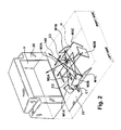
FIG. 2 is a perspective view of the reader ofFIG. 1 with a portion of the reader housing removed to illustrate three cameras forming a portion of a plurality of cameras located on a printed circuit board; -
FIGS. 3 and 4 are perspective views showing a position of three additional cameras forming a portion of a plurality of cameras located on a printed circuit board resulting in a total of six cameras constructed in accordance with one example embodiment of the present disclosure; -
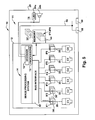
FIG.5 is a schematic block diagram of selected systems and electrical circuitry of the bar code reader ofFIG. 1 ; -
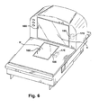
FIG. 6 is a perspective view of an imaging dual window scanner constructed in accordance with another example embodiment of the present disclosure; -
FIG 7 is a perspective view of an illumination component associated with one camera system of a multi-camera system bar code reader; and -
FIG 8 is a frame sequence of exposure time slices for a bar code reader having multiple cameras. -
FIG 1 depicts a stationarybar code reader 10 having an imaging and decoding system supported within aninterior region 18 of ahousing 20. Thehousing 20 may be integrated into a sales counter of a point of sales system that includes, for example, a cash register, a touch screen visual display or other type user interface and a printer for generating sales receipts. Thehousing 20 depicted inFIG. 1 includes two transparent windows H, V so that objects moved past the housing can be imaged. - In accordance with one use, either a sales person or a customer will swipe a product or
target object 32 selected for purchase relative to thehousing 20. Atarget bar code 30 imprinted or affixed to thetarget object 32 is swiped through a region near the windows H, V for reading, that is, imaging and decoding of the coded indicia of the target bar code. - An
exemplary imaging system 12 has six cameras C1 - C6 that capture a series of image frames in a programmable way under the control of a processor orprocessors 15. The series of image frames for each camera assembly C1-C6 is shown schematically as IF1, IF2, IF3, IF4, IF5, IF6 inFIG. 5 . Each series of image frames IF1-IF6 comprises a sequence of individual image frames generated by the respective cameras C1-C6 at times controlled by theprocessors 15. The designation IF1, for example, represents multiple successive images obtained from the camera C1. - Digital signals 35 that make up the frames are coupled to a
bus interface 42, where the signals are multiplexed and then communicated to amemory 44 in an organized fashion so that the processor knows which image representation belong to a given camera.Image processors 15 access the image frames IF1-IF6 frommemory 44 and search for image frames that include an imaged target bar code 30'. If the imaged target bar code 30' is present and decodable in one or more image frames, adecoder 16 attempts to decode the imaged target bar code 30' using one or more of the image frames having the imaged target bar code 30'. - Each of the cameras has a two-dimensional (2D) CMOS image capture array with a typical size of the pixel array being on the order of 752 x 480 pixels. The illumination-receiving pixels of the sensor array define a sensor array surface secured to a printed circuit board for stability. The sensor array surface is substantially perpendicular to an optical axis of the imaging lens assembly, that is, an axis that is perpendicular to the sensor array surface would be substantially parallel to the optical axis of the focusing lens. The pixels of the sensor array surface are disposed in an orthogonal arrangement of rows and columns of pixels.
- A rolling shutter in a CMOS image sensor resets rows of pixels in sequence. As an example, the shutter starts at the top of the image and proceeds row by row to the bottom, resetting each row. When the reset process has moved some distance down the image, the readout process begins at the top. Rows of pixels are read out in sequence, starting at the top of the image and proceeding row by row to the bottom in exactly the same fashion and at the same speed as the reset process. The time delay between a row being reset and a row being read is the integration time. By varying the amount of time between when the reset sweeps past a row and when the readout of the row takes place, the integration time (hence the exposure) can be controlled for a sensor having a rolling shutter. Since the integration process moves through the image over some length of time, motion artifacts may occur and if a bar code is present on a moving object swiped in front of the reader, the bar code may not be decodeable.
- A global shutter operates differently. When a global shutter is used, the entire image is reset before integration of the pixel contributions to the image. The pixels are allowed to accumulate charge during an integration time. At the end of the integration time, the accumulated charge in each pixel is simultaneously transferred to a light shielded storage area. Then the signals are read out from the light shielded area. Since all pixels are reset at the same time, integrated over the same interval, motion artifacts are avoided. A representative sensor having a global shutter is commercially available from Aptina (formerly Micron) under the part designation MT9V022.
- An exemplary system uses one or more light emitting diodes closely spaced from an associated sensor array for each of the cameras C1 - C6. The LEDs are selectively activated to emit light under control of the
processors 15. This is shown more clearly in the schematic depiction ofFigure 8 . - As is best seen in
FIG. 5 , thedigital signals 35 are received by abus interface 42 of animage processing system 14, which serializes the image data contained in thedigital signals 35. The digitized values of the digitizedsignal 35 are stored in thememory 44. - The
decoding circuitry 14 performs a process on selected image frames by getting an image from memory and determining if the image has a bar code. If so, adecoder 16 attempts to decode any decodable image within the image frames, e.g., the imaged target bar code 30'. If the decoding is successful, decodeddata 56, representative of the data/information coded in thetarget bar code 30 is then output via adata output port 58 and/or displayed to a user of thereader 10 via adisplay 59. Upon achieving a good read of thetarget bar code 30, that is, thebar code 30 was successfully imaged and decoded, aspeaker 34b and/or anindicator LED 34a is activated by the barcode reader circuitry 11 to indicate to the user that thetarget bar code 30 has been successfully read. - Referring now to
FIG. 2 , an exemplary dual window bar code reader includes a printedcircuit board 22 that supports six imaging cameras. Three cameras having a field-of-view extending from a generally horizontal window H are shown, namely C1, C2, and C3. Camera or imager C1 and its associated optics faces generally vertically upward toward an inclined folding mirror M1A substantially directly overhead at a left side of the horizontal window H. The folding mirror M1A faces another inclined narrow folding mirror M1B located at a right side of the horizontal window H. The folding mirror M1B faces still another inclined wide folding mirror M1C adjacent the mirror M1A. The folding mirror M1C faces out through the generally horizontal window H toward the right side of the dual window scanner. A region of imaging coverage resulting from the field-of-view projected from camera C1 is produced, substantially filling a scanning area of the horizontal window H. - The camera or imager C3 and its associated optics are symmetric with respect to a center line of the reader to imager C1. Camera C3 faces generally vertically upward toward an incline folding mirror M3A substantially directly overhead at a right side of the horizontal window H. The folding mirror M3A faces another inclined narrow folding mirror M3B located at a left side of the horizontal window H. The folding mirror M3B faces still another inclined wide folding mirror M3C adjacent the mirror M3A. The folding mirror M3C faces out through the generally horizontal window H toward the left side of the dual window reader.
- Imager or camera C2 and its associated optics are located between imagers C1 and C3 and their associated optics. Imager C2 faces generally vertically upward toward an inclined folding mirror M2A substantially directly overhead generally centrally of the horizontal window H at one end thereof. The folding mirror M2A faces another inclined folding mirror M2B located at the opposite end of the horizontal window H. The folding mirror M2B faces out through the window H in an upward direction toward the vertical window V in the
housing 20. - As illustrated in
FIG. 3 , the dual window reader has a camera or imager C4 and its associated optics that faces generally vertically upward toward an incline folding mirror M4A substantially directly overhead at a left side of the vertical window V. The folding mirror M4A faces another inclined narrow folding mirror M4B located at a right side of the vertical window V. The folding mirror M4B faces still another inclined wide folding mirror M4C adjacent the mirror M4A. The folding mirror M4C faces out through the generally vertical window V toward the right side of the dual window reader. - In
FIG. 4 camera or imager C6 and its associated optics is mirror symmetrical to imager C4. Camera C6 faces generally vertically upward toward an incline folding mirror M6A substantially directly overhead at a right side of the vertical window V. The folding mirror M6A faces another inclined narrow folding mirror M6B located at a left side of the vertical window V. The folding mirror M6B faces still another inclined wide folding mirror M6C adjacent the mirror M6A. The folding mirror M6C faces out through the generally vertical window V toward the left side of the dual window reader. - In
FIG. 4 , imager or camera C5 and its associated optics are located generally centrally between imagers C4 and C6 and their associated optics. Imager C5 faces generally vertically upward toward an inclined folding mirror M5A substantially directly overhead generally centrally of the vertical window V at one end thereof. The folding mirror M5A faces out through the window V in a downward direction toward the horizontal window H in thehousing 20. - Features and functions of the fold mirrors shown in
figures 2 - 4 are described in further detail inUS2009/026271 A1 to Drzymala et al filed October 3, 2008 . The depictions in the co-pending application show optical layouts which represent one or more fold mirrors that achieve long path lengths within the reader housing. In the Figures two or three fold mirrors are used to define a given field of view. Other numbers of mirrors, however, could be used to direct light to a field of view outside the housing. - Each of the multiple cameras has its own dedicated light source for illuminating that camera's field of view. The light source is only energized when its associated camera is capturing an image. Turning to
figure 7 , one sees a camera assembly C1 having two spaced apartlight emitting diodes 120, 122 (Although in the exemplary embodiment, two LEDs are used for each camera, more or less than two could be used) that are closely adjacent to asensor array 124. The light emitting diodes direct light through associated combination light pipe and lens systems. When a firstlight emitting diode 120 is energized light passes through a light pipe and twolenses lens 127 and impacts thesensor array 124. A secondlight emitting diode 122 is energized simultaneously with thefirst LED 120 and light passes through a light pipe and twolenses second Led 122 reflects off the object passes through thelens 127 and impacts thesame sensor array 124. In the exemplary embodiment theLEDs sensor array 124. - The illumination intensity provided by the
diodes FIG 8 ), each ending its exposure before the next is energized. When all N imagers (six in the exemplary embodiment) have captured images the sequence repeats. To achieve 60 frames per second from 6 cameras, the 16.66 milliseconds total frame time must be time sliced to 2.77 millisecond camera allocations. - This time slicing allows the cameras C1 - C6 to operate at an exposure time that is sufficient, but not much greater than is necessary to produce a decodable image at maximum desired range. At close range, however, this exposure time will be longer than necessary, and may be too long to allow the desired swipe speed due to image blur. It is therefore necessary to reduce the exposure time when barcodes are positioned closer to the scanner, and this reduction must be accomplished without wasting any frames.
- A photo-detector sensor 150 (
FIG 7 ) associated with each camera that uses auto-exposure (in a multiple camera system not all imagers will necessarily need auto-exposure), is positioned such that return light from an associated window field of view corresponds to a portion of the field of view of theimage sensor 124. For example, one auto-exposure sensor 150 has a field of view whose light is focused by alens 148 that is 75% of the size of the field of view of theimager array 124, and which is positioned to be entirely within the field of view of the imager over the majority of the desired working range of the scanner. To assure that the field of view of thesensor 150 falls entirely within the field of view of thesensor 124, the field of view of theauto exposure sensor 150 is tilted a slight amount ( < five degrees) so its field of view is approximately centered within the field of view of thesensor 124 within the working range of the camera C1. - When the
diodes sensor 150 is integrated until the integrator exceeds a threshold value, at which time thediodes sensor 124. Theimage sensor 124 continues its exposure until its preset exposure time is reached, but since the illumination from theLEDs - Use of a global shutter assures that the time during which the
sensor 124 is exposing is minimized, so the opportunity for interference from ambient light is far reduced. With a rolling shutter, at least part of the frame may be exposing for as much as 30 ms (the rolling shutter sensor runs at a maximum of 30 frames/second), but the required exposure time, and therefore the duration of the illumination flash may be as little as, for example, 300us. The image that is captured during the flash of illumination therefore can be corrupted during the remainder of the 30 ms exposure time. - When a
sensor 124 with a global shutter is used, the time during which the illumination flash has ended but the sensor is still exposing is only perhaps 100 us, assuming the maximum exposure time has been set to 400 us, so ambient light will have little influence on the ultimate brightness of the image. No optical filter is needed since the influence of ambient light has already been minimized. - The maximum exposure time of the
reader 10 is changed based on the light transmission efficiency of the scan window H, V. The light reflected off from the barcodes and received by the imagers can vary due to variations in distance from the scanner or variations in the kind of window that is installed on the scanner. For example scanner windows might be tempered glass which transmits around 90% of incident light. Windows made from glass with a scratch resistant diamond-like coating (DLC) transmits light at a 55% efficiency. The window or windows can include a thin coating of sapphire laminated to a glass substrate which transmit light with 72% efficiency at a wavelength of 630 nm, the wavelength of LED illumination systems used with exemplary cameras. These transmission efficiencies are typical for light passing through a window at 45 degrees, which is common for existing imagers. - If a DLC window is being used, maximum exposure time can be set, for example, to 400 usecs, but when a sapphire window is used maximum time can be set to 250 usecs, since the superior light transmission of the sapphire window will never require a longer exposure time. Reducing the maximum exposure time when a higher transmission window is used minimizes the impact of ambient light, which is transmitted more easily through the higher transmission window, and also avoids increasing the duration of an illumination flash more than necessary when no object is within the field of view, in which case the auto-exposure system will turn the flash duration up to maximum, since no reflected light is detected. Regardless of the maximum exposure time, both the actual shutter exposure time of the sensor and the maximum illumination flash duration will be set to be around the same. The auto-exposure control implemented by the processors can reduce illumination flash duration, but would generally not be allowed to produce a flash whose duration exceeds the maximum exposure duration, since any such prolonged flash is wasted, annoying to the user and needlessly increases power consumption of the scanner.
- In order to utilize different maximum exposure times for different kinds of windows, the scanner must be able to identify which window has been installed. This can be accomplished several ways. A barcode 160 (
FIG 6 ) can be placed inside the window, or adjacent to the inside of the window where at least one of the cameras can read it. The barcode can identify the kind of window next to which it is positioned, causing the reader to operate at a predetermined maximum exposure time for that window. Alternatively, the barcode can directly indicate what maximum exposure time should be used for that window. Another possibility is to mount amagnet 165 in the frame that holds the window of one kind of window, and not in the window frame of the other kind of window. When a window is installed, amagnetic sensor 170, such as a reed switch or hall-effect sensor can be positioned to detect the magnet. If it doesn't detect a magnet one maximum exposure time is enabled. If it does detect a magnet a different maximum exposure time is selected. installs the window, to set-up the scanner with the appropriate maximum exposure time for that window. - In some multi-camera bar code readers auto-exposure cameras are needed on only a subset of the imagers. As discussed above in the disclosed
reader 10, three of the cameras obtain images through the vertical window V and three other cameras obtain images through the horizontal window H. The vertical window V is not subject to the same abuse as the horizontal windows, which must survive even though metal objects such as cans of food and tools will be dragged across it. Therefore scratch resistant window materials such as DLC and Sapphire are not generally used for the vertical window in such bar code readers. Vertical windows can be made, for example, of tempered glass, which has better optical transmission characteristics than either Sapphire or DLC. With this superior optical transmission, it is possible to project enough light to use a very short exposure time even when scanning at maximum range. There is therefore no need to increase exposure time to achieve full range, as is necessary when scanning through windows with lower transmission. Imagers that look through high transmission windows can therefore operate with fixed exposure times, in which the flash duration and sensor shutter exposure time are matched at a preset value. This eliminates the need to implement auto exposure with some of the imagers, reducing system cost. - A bar code reader built in accordance with this invention can therefore use auto exposure on only a subset of the cameras. Alternatively, all imagers can use an auto-exposure system as described above, including the imagers that look through a high transmission window. Providing these imagers with an auto-exposure system will cause them to operate with shorter exposure durations when barcodes are scanned close to the window, as is commonly the case. Shorter exposures increase the scanners ability to capture undistorted images of moving objects, so the addition of the auto-exposure system will increase the allowable swipe speed when barcodes are being scanned at closer then maximum range.
- What have been described above are examples of the present invention. It is, of course, not possible to describe every conceivable combination of components or methodologies for purposes of describing the present invention, but one of ordinary skill in the art will recognize that many further combinations and permutations of the present invention are possible. Accordingly, the present invention is intended to embrace all such alterations, modifications and variations that fall within the scope of the appended claims.
Claims (13)
- A bar code reader (10) for reading bar codes (30) comprising:a housing (20) including one or more transparent windows and defining a housing interior region (18) so that a target object (32) swiped or presented in relation to the transparent windows can be evaluated for a presence of a bar code (30);a plurality of cameras supported within the interior region (18) of the housing (20), each camera having an image capture sensor array (124) for capturing an image of a bar code (30) within an associated camera field of view and a light source for illuminating said field of view associated with said camera;a processing system (15) coupled to the plurality of cameras for decoding a bar code (30) carried by the target object (32) from images captured by the plurality of cameras, said processor (15) sequentially activating the light source of each given camera selected from the plurality of cameras in synchronism with activating an exposure by the image capture sensor array of the each given camera to allocate different time segments within an image frame period to different cameras amongst the plurality of cameras;characterised by:an indicia indicating the material of said one or more windows and wherein a maximum exposure time for a sensor array is adjusted based on the indicated transmissivity of the material of a window through which light passes on its way to the sensor array.
- The bar code reader (10) of claim 1 additionally comprising a plurality of light sensors coupled to the processing system (15) wherein each light sensor monitors a field of view of an associated camera and the processing system (15) adjusts illumination time of the cameras based on sensed light.
- The bar code reader (10) of claim 2 wherein the light sensor associated with a given camera evaluates an amount of light returning from the camera field of view and the processing system (15) terminates illumination of an associated camera field of view when a threshold amount of light has been sensed.
- The bar code reader (10) of claim 1 wherein at least some of said plurality of cameras comprise a global shutter having the adjustable exposure time.
- The bar code reader (10) of claim 4 wherein the window of the one or more transparent windows is the window through which light passes on its way to a field of view.
- The bar code reader (10) of claim 1 comprising a sensor for automatically determining the light transmissivity of the material of at least one window and wherein the processing system (15) adjusts an exposure time for cameras whose field of view extends through said at least one window based on the light transmissivity of the material.
- The bar code reader (10) of claim 1 wherein at least some of said plurality of cameras comprise a global shutter having the adjustable exposure time and said adjustable exposure time is chosen to be less than 500 microseconds based on a working range of the camera.
- A method for imaging a target bar code (30) comprising:providing a housing (20) having one or more transparent windows that define a region for movement of an object (32) having a bar code (30);positioning multiple cameras in the housing (20) wherein each of said multiple cameras includes an associated sensor array (124) having a global shutter for imaging bar codes (30) on objects (32) outside the housing (20)within an associated field of view and a light source for illuminating said field of view associated with said camera;gathering multiple images from different cameras by:characterised by:exposing a first image from a first camera field of view as light reflected from said field of view impinges onto a first sensor array in synchronism with activating the light source associated with the first camera field of view; andsubsequent to exposing the first image, exposing other images from one or more additional camera fields of view as light reflected from said one or more additional fields of view impinges onto one or more additional sensor arrays in synchronism with activating the light source associated with each of the one or more additional camera fields of view so that the images of the cameras are obtained during a frame period of 1/30 seconds or less;reading an indicia for indicating the material of said one or more windows and wherein a maximum exposure time for a sensor array is adjusted based on the indicated material of a window through which light passes on its way to the sensor array.
- The method of claim 8, wherein the cameras are adjustable exposure cameras and additionally comprising illuminating an associated field of view for each of the adjustable exposure cameras, sensing light reflected from each associated camera field of view and terminating the illumination for said associated field of view after a threshold amount of light has been reflected from said field of view.
- The method of claim 8 additionally positioning a plurality of light sensors for monitoring a field of view of an associated camera and adjusting an illumination time based on an amount of light reflected from the camera's field of view.
- The method of claim 10 wherein of the window of the one or more transparent windows is the window through which light passes on its way to a sensor.
- The method of claim 9 wherein the housing (20) supports at least some cameras without adjustable exposures and these cameras also obtain images within the frame period.
- The method of claim 8 comprising a sensor for automatically determining the transmissivity of the material of at least one window and wherein the processing system adjusts an exposure time for cameras whose field of view extends through said at least one window based on the transmissivity of the material.
Applications Claiming Priority (2)
| Application Number | Priority Date | Filing Date | Title |
|---|---|---|---|
| US12/417,287 US8146821B2 (en) | 2009-04-02 | 2009-04-02 | Auto-exposure for multi-imager barcode reader |
| PCT/US2010/029001 WO2010114782A1 (en) | 2009-04-02 | 2010-03-29 | Auto-exposure for multi-imager barcode reader |
Publications (2)
| Publication Number | Publication Date |
|---|---|
| EP2414988A1 EP2414988A1 (en) | 2012-02-08 |
| EP2414988B1 true EP2414988B1 (en) | 2015-09-02 |
Family
ID=42359522
Family Applications (1)
| Application Number | Title | Priority Date | Filing Date |
|---|---|---|---|
| EP10726689.2A Active EP2414988B1 (en) | 2009-04-02 | 2010-03-29 | Auto-exposure for multi-imager barcode reader |
Country Status (4)
| Country | Link |
|---|---|
| US (2) | US8146821B2 (en) |
| EP (1) | EP2414988B1 (en) |
| CN (1) | CN102369538B (en) |
| WO (1) | WO2010114782A1 (en) |
Families Citing this family (53)
| Publication number | Priority date | Publication date | Assignee | Title |
|---|---|---|---|---|
| US8042740B2 (en) | 2000-11-24 | 2011-10-25 | Metrologic Instruments, Inc. | Method of reading bar code symbols on objects at a point-of-sale station by passing said objects through a complex of stationary coplanar illumination and imaging planes projected into a 3D imaging volume |
| US7841533B2 (en) | 2003-11-13 | 2010-11-30 | Metrologic Instruments, Inc. | Method of capturing and processing digital images of an object within the field of view (FOV) of a hand-supportable digitial image capture and processing system |
| US8608076B2 (en) * | 2008-02-12 | 2013-12-17 | Datalogic ADC, Inc. | Monolithic mirror structure for use in a multi-perspective optical code reader |
| US8678287B2 (en) | 2008-02-12 | 2014-03-25 | Datalogic ADC, Inc. | Two-plane optical code reader for acquisition of multiple views of an object |
| EP2248069B1 (en) | 2008-02-12 | 2013-08-28 | Datalogic ADC, Inc. | Systems and methods for forming a composite image of multiple portions of an object from multiple perspectives |
| US8353457B2 (en) * | 2008-02-12 | 2013-01-15 | Datalogic ADC, Inc. | Systems and methods for forming a composite image of multiple portions of an object from multiple perspectives |
| US8261990B2 (en) * | 2008-12-26 | 2012-09-11 | Datalogic ADC, Inc. | Data reader having compact arrangement for acquisition of multiple views of an object |
| US8322621B2 (en) | 2008-12-26 | 2012-12-04 | Datalogic ADC, Inc. | Image-based code reader for acquisition of multiple views of an object and methods for employing same |
| US8146821B2 (en) * | 2009-04-02 | 2012-04-03 | Symbol Technologies, Inc. | Auto-exposure for multi-imager barcode reader |
| US8408464B2 (en) * | 2011-02-03 | 2013-04-02 | Metrologic Instruments, Inc. | Auto-exposure method using continuous video frames under controlled illumination |
| US8469272B2 (en) | 2011-03-29 | 2013-06-25 | Metrologic Instruments, Inc. | Hybrid-type bioptical laser scanning and imaging system supporting digital-imaging based bar code symbol reading at the surface of a laser scanning window |
| US9033236B2 (en) * | 2011-04-26 | 2015-05-19 | Symbol Technologies, Inc. | Point-of-transaction workstation for and method of imaging indicia over full coverage scan zone occupied by unskewed subfields of view |
| US8794525B2 (en) | 2011-09-28 | 2014-08-05 | Metologic Insturments, Inc. | Method of and system for detecting produce weighing interferences in a POS-based checkout/scale system |
| US8561905B2 (en) | 2011-06-15 | 2013-10-22 | Metrologic Instruments, Inc. | Hybrid-type bioptical laser scanning and digital imaging system supporting automatic object motion detection at the edges of a 3D scanning volume |
| US8939371B2 (en) | 2011-06-30 | 2015-01-27 | Symbol Technologies, Inc. | Individual exposure control over individually illuminated subfields of view split from an imager in a point-of-transaction workstation |
| US8371505B1 (en) | 2011-08-15 | 2013-02-12 | Psion, Inc. | System and method for compensating for motion relative to a barcode |
| US8389945B1 (en) * | 2011-08-25 | 2013-03-05 | Symbol Technologies, Inc. | Object detecting system in imaging-based barcode readers |
| US8590792B2 (en) * | 2011-09-14 | 2013-11-26 | Symbol Technologies, Inc. | Apparatus for and method of reading printed and electronic codes |
| US8967473B2 (en) * | 2011-11-30 | 2015-03-03 | Ncr Corporation | Scanner, method and system for processing images in an imaging based optical code scanner |
| US11966810B2 (en) | 2012-02-06 | 2024-04-23 | Cognex Corporation | System and method for expansion of field of view in a vision system |
| US9892298B2 (en) | 2012-02-06 | 2018-02-13 | Cognex Corporation | System and method for expansion of field of view in a vision system |
| US9027838B2 (en) | 2012-02-06 | 2015-05-12 | Cognex Corporation | System and method for expansion of field of view in a vision system |
| USD709888S1 (en) * | 2012-07-02 | 2014-07-29 | Symbol Technologies, Inc. | Bi-optic imaging scanner module |
| US8678274B1 (en) | 2012-08-30 | 2014-03-25 | Symbol Technologies, Inc. | Point-of-transaction checkout system for and method of processing targets electro-optically readable by a clerk-operated workstation and by a customer-operated accessory reader |
| CN103679108B (en) * | 2012-09-10 | 2018-12-11 | 霍尼韦尔国际公司 | Optical markings reading device with multiple images sensor |
| CN107657197B (en) * | 2012-09-25 | 2020-07-28 | 霍尼韦尔国际公司 | IC chip imager based on package-on-package |
| CN103699861B (en) | 2012-09-27 | 2018-09-28 | 霍尼韦尔国际公司 | Coding information reading terminals with multiple image-forming assemblies |
| US8998089B2 (en) * | 2013-01-03 | 2015-04-07 | Symbol Technologies, Inc. | Method of controlling illumination pulses to increase dynamic range in bioptic imager barcode scanner |
| EP2808834B1 (en) | 2013-05-29 | 2017-07-12 | BDT Media Automation GmbH | Method and apparatus for detecting and determining the presence of objects in storage facilities using a bar code reading device |
| USD723560S1 (en) | 2013-07-03 | 2015-03-03 | Hand Held Products, Inc. | Scanner |
| CN103530592B (en) * | 2013-11-04 | 2016-08-03 | 福建新大陆自动识别技术有限公司 | Bar code identifying device and projected graphics control method thereof |
| USD730901S1 (en) | 2014-06-24 | 2015-06-02 | Hand Held Products, Inc. | In-counter barcode scanner |
| US9521331B2 (en) * | 2015-04-21 | 2016-12-13 | Hand Held Products, Inc. | Capturing a graphic information presentation |
| US10244180B2 (en) * | 2016-03-29 | 2019-03-26 | Symbol Technologies, Llc | Imaging module and reader for, and method of, expeditiously setting imaging parameters of imagers for imaging targets to be read over a range of working distances |
| US10331926B1 (en) * | 2017-12-18 | 2019-06-25 | Symbol Technologies, Llc | Bi-optic barcode reader |
| CN108416238B (en) * | 2018-01-31 | 2021-04-13 | 深圳盈达信息科技有限公司 | Laser scanning module and method for shielding laser interference |
| WO2020085331A1 (en) * | 2018-10-23 | 2020-04-30 | 株式会社デンソーウェーブ | Information-code reading device |
| CN109361873A (en) * | 2018-12-10 | 2019-02-19 | 成都泓睿科技有限责任公司 | A kind of High-speed Control light source camera Triggering Control System and control method |
| US11151344B2 (en) * | 2019-07-08 | 2021-10-19 | Zebra Technologies Corporation | Systems and method for enabling selective use of illumination color to capture appropriate data |
| EP3886427A1 (en) * | 2020-03-27 | 2021-09-29 | Leuze electronic GmbH + Co. KG | Optical sensor and method for detecting objects using an optical sensor |
| US11295163B1 (en) | 2020-04-01 | 2022-04-05 | Scandit Ag | Recognition of optical patterns in images acquired by a robotic device |
| US11216628B2 (en) * | 2020-04-01 | 2022-01-04 | Scandit Ag | High-speed scanning of optical patterns using a digital camera |
| US11514665B2 (en) | 2020-04-01 | 2022-11-29 | Scandit Ag | Mapping optical-code images to an overview image |
| JP7514693B2 (en) * | 2020-08-13 | 2024-07-11 | 東芝テック株式会社 | Payment Device |
| JP7505939B2 (en) * | 2020-08-21 | 2024-06-25 | 東芝テック株式会社 | Payment Device |
| US12175327B1 (en) | 2020-12-04 | 2024-12-24 | Scandit Ag | Camera start optimization for optical pattern decoding |
| US11816529B2 (en) | 2021-01-11 | 2023-11-14 | Zebra Technologies Corporation | Methods and apparatus for providing out-of-range indications for imaging readers |
| US11616901B2 (en) | 2021-03-29 | 2023-03-28 | Advanced Micro Devices, Inc. | Adaptive lens step control with multiple filters for camera fast auto focus |
| US11343438B1 (en) | 2021-03-29 | 2022-05-24 | Advanced Micro Devices, Inc. | Instant auto exposure control with multiple cameras |
| EP4124991B1 (en) * | 2021-07-30 | 2023-11-15 | Sick Ag | Method for automatically setting up a code reading device and camera-based code reading device |
| US12585904B2 (en) * | 2022-06-13 | 2026-03-24 | Datalogic Ip Tech S.R.L. | Dynamic diffusive illumination systems and methods |
| CN117494740A (en) * | 2023-11-06 | 2024-02-02 | 广州讯宝电子科技有限公司 | A dual-camera scanner scanning method |
| DE202024105742U1 (en) * | 2024-10-04 | 2026-02-19 | Leuze Electronic Gmbh + Co. Kg | Optical sensor |
Family Cites Families (70)
| Publication number | Priority date | Publication date | Assignee | Title |
|---|---|---|---|---|
| US4613895A (en) | 1977-03-24 | 1986-09-23 | Eastman Kodak Company | Color responsive imaging device employing wavelength dependent semiconductor optical absorption |
| KR900007137B1 (en) * | 1985-11-06 | 1990-09-29 | 닛뽕 덴소오 가부시기가이샤 | Optical information reading apparatus |
| US4794239A (en) | 1987-10-13 | 1988-12-27 | Intermec Corporation | Multitrack bar code and associated decoding method |
| US5304786A (en) | 1990-01-05 | 1994-04-19 | Symbol Technologies, Inc. | High density two-dimensional bar code symbol |
| US5124539A (en) | 1989-06-16 | 1992-06-23 | Symbol Technologies, Inc. | Scan pattern generators for bar code symbol readers |
| US5200599A (en) | 1989-06-16 | 1993-04-06 | Symbol Technologies, Inc | Symbol readers with changeable scan direction |
| US5059779A (en) | 1989-06-16 | 1991-10-22 | Symbol Technologies, Inc. | Scan pattern generators for bar code symbol readers |
| US5093422A (en) * | 1990-04-23 | 1992-03-03 | Shell Oil Company | Low stress relaxation extrudable elastomeric composition |
| JPH04245581A (en) * | 1991-01-31 | 1992-09-02 | Sumitomo Electric Ind Ltd | Scanning speed detecting device and symbol reader using it |
| US5491328A (en) * | 1991-09-24 | 1996-02-13 | Spectra-Physics Scanning Systems, Inc. | Checkout counter scanner having multiple scanning surfaces |
| JPH0793459A (en) * | 1993-09-28 | 1995-04-07 | Tec Corp | Two-dimensional code scanner |
| US7051922B2 (en) * | 1994-08-17 | 2006-05-30 | Metrologic Instruments, Inc. | Compact bioptical laser scanning system |
| US5559562A (en) | 1994-11-01 | 1996-09-24 | Ferster; William | MPEG editor method and apparatus |
| US5703349A (en) | 1995-06-26 | 1997-12-30 | Metanetics Corporation | Portable data collection device with two dimensional imaging assembly |
| JP3441580B2 (en) * | 1995-12-14 | 2003-09-02 | 富士通株式会社 | Reader |
| US6254003B1 (en) * | 1995-12-18 | 2001-07-03 | Welch Allyn Data Collection, Inc. | Optical reader exposure control apparatus comprising illumination level detection circuitry |
| US5859418A (en) * | 1996-01-25 | 1999-01-12 | Symbol Technologies, Inc. | CCD-based bar code scanner with optical funnel |
| US5717195A (en) | 1996-03-05 | 1998-02-10 | Metanetics Corporation | Imaging based slot dataform reader |
| JPH11265249A (en) * | 1998-03-17 | 1999-09-28 | Toshiba Corp | Information input device, information input method, and recording medium |
| US6141062A (en) | 1998-06-01 | 2000-10-31 | Ati Technologies, Inc. | Method and apparatus for combining video streams |
| JP2000035547A (en) * | 1998-07-17 | 2000-02-02 | Fujitsu Ltd | Optical reader having tiltable stage on which optical unit is mounted |
| US6317152B1 (en) | 1999-07-17 | 2001-11-13 | Esco Electronics Corporation | Digital video recording system |
| US6296187B1 (en) * | 1999-11-12 | 2001-10-02 | Psc Inc. | CCD-based bar code scanner |
| US6924807B2 (en) | 2000-03-23 | 2005-08-02 | Sony Computer Entertainment Inc. | Image processing apparatus and method |
| US6899272B2 (en) * | 2000-05-17 | 2005-05-31 | Symbol Technologies, Inc | Bioptics bar code reader |
| US7076097B2 (en) | 2000-05-29 | 2006-07-11 | Sony Corporation | Image processing apparatus and method, communication apparatus, communication system and method, and recorded medium |
| US8042740B2 (en) * | 2000-11-24 | 2011-10-25 | Metrologic Instruments, Inc. | Method of reading bar code symbols on objects at a point-of-sale station by passing said objects through a complex of stationary coplanar illumination and imaging planes projected into a 3D imaging volume |
| US7128266B2 (en) | 2003-11-13 | 2006-10-31 | Metrologic Instruments. Inc. | Hand-supportable digital imaging-based bar code symbol reader supporting narrow-area and wide-area modes of illumination and image capture |
| US7268924B2 (en) * | 2001-01-22 | 2007-09-11 | Hand Held Products, Inc. | Optical reader having reduced parameter determination delay |
| US6766954B2 (en) | 2001-06-15 | 2004-07-27 | Symbol Technologies, Inc. | Omnidirectional linear sensor-based code reading engines |
| US7457476B2 (en) * | 2001-10-03 | 2008-11-25 | Anoto Ab | Optical sensor device and a method of controlling its exposure time |
| SE0103286L (en) * | 2001-10-03 | 2003-04-04 | Anoto Ab | Optical sensor device and method for controlling its exposure time |
| US7257325B1 (en) * | 2002-09-24 | 2007-08-14 | Avanex Corporation | Method and system for monitoring multiple optical communications lines |
| US20040146211A1 (en) | 2003-01-29 | 2004-07-29 | Knapp Verna E. | Encoder and method for encoding |
| US7637430B2 (en) * | 2003-05-12 | 2009-12-29 | Hand Held Products, Inc. | Picture taking optical reader |
| US8306128B2 (en) | 2004-05-21 | 2012-11-06 | Texas Instruments Incorporated | Clocked output of multiple data streams from a common data port |
| US6974083B1 (en) | 2004-07-23 | 2005-12-13 | Symbol Technologies, Inc. | Point-of-transaction workstation for electro-optically reading one-dimensional indicia, including image capture of two-dimensional targets |
| US7748631B2 (en) * | 2004-07-29 | 2010-07-06 | Symbol Technologies, Inc. | Point-of-transaction workstation for electro-optically reading one-dimensional and two-dimensional indicia by image capture |
| EP1626584A3 (en) | 2004-08-11 | 2009-04-08 | Magna Donnelly GmbH & Co. KG | Vehicle with image processing system and method of operating an image processing system |
| WO2006060785A2 (en) * | 2004-12-01 | 2006-06-08 | Datalogic Scanning, Inc. | Triggering illumination for a data reader |
| US7204418B2 (en) * | 2004-12-08 | 2007-04-17 | Symbol Technologies, Inc. | Pulsed illumination in imaging reader |
| WO2006062818A2 (en) * | 2004-12-08 | 2006-06-15 | Symbol Technologies, Inc. | Swipe imager scan engine |
| US7634277B2 (en) | 2005-04-28 | 2009-12-15 | Cisco Technology, Inc. | Method for allocating channel resources for improving frequency utilization efficiency of wireless communication systems |
| US7430682B2 (en) | 2005-09-30 | 2008-09-30 | Symbol Technologies, Inc. | Processing image data from multiple sources |
| US20090020611A1 (en) * | 2005-09-30 | 2009-01-22 | Symbol Technologies, Inc. | Bi-optic imaging scanner with preprocessor for processing image data from multiple sources |
| US7748629B2 (en) * | 2006-01-31 | 2010-07-06 | Symbol Technologies, Inc. | Extended working range illumination system for an imaging-based bar code reader |
| US7344080B2 (en) * | 2006-03-31 | 2008-03-18 | Symbol Technologies, Inc. | Imaging-based bar code reader utilizing stitching method and swipe guide |
| CN200979606Y (en) * | 2006-04-27 | 2007-11-21 | 天津师范大学 | A raster single-forming device |
| US7475823B2 (en) * | 2006-05-26 | 2009-01-13 | Symbol Technologies, Inc. | Hand held bar code reader with improved image capture |
| US20080105745A1 (en) * | 2006-09-19 | 2008-05-08 | Ming Lei | Devices and/or systems for illuminating barcodes |
| US7533819B2 (en) * | 2007-01-31 | 2009-05-19 | Symbol Technologies, Inc. | Dual camera assembly for an imaging-based bar code reader |
| US8033472B2 (en) * | 2007-06-28 | 2011-10-11 | Symbol Technologies, Inc. | Electro-optical imaging reader having plural solid-state imagers with shutters to prevent concurrent exposure |
| US7757955B2 (en) * | 2008-04-30 | 2010-07-20 | Symbol Technologies, Inc. | Bar code reader having multiple cameras |
| US8505824B2 (en) * | 2007-06-28 | 2013-08-13 | Symbol Technologies, Inc. | Bar code readers having multifold mirrors |
| US20090020612A1 (en) * | 2007-06-28 | 2009-01-22 | Symbol Technologies, Inc. | Imaging dual window scanner with presentation scanning |
| US8662397B2 (en) * | 2007-09-27 | 2014-03-04 | Symbol Technologies, Inc. | Multiple camera imaging-based bar code reader |
| US8567680B2 (en) * | 2007-12-20 | 2013-10-29 | Ncr Corporation | Method, device and system for a laser bar code scanner with imaging assist |
| US8353457B2 (en) * | 2008-02-12 | 2013-01-15 | Datalogic ADC, Inc. | Systems and methods for forming a composite image of multiple portions of an object from multiple perspectives |
| US20100019043A1 (en) * | 2008-07-23 | 2010-01-28 | William Sackett | Electro-optical imaging reader having plural solid-state imagers with nonconcurrent exposure |
| US8622305B2 (en) * | 2008-07-23 | 2014-01-07 | Symbol Technologies, Inc. | Efficient multi-image bar code reader |
| US20100102129A1 (en) * | 2008-10-29 | 2010-04-29 | Symbol Technologies, Inc. | Bar code reader with split field of view |
| US8479996B2 (en) * | 2008-11-07 | 2013-07-09 | Symbol Technologies, Inc. | Identification of non-barcoded products |
| US8079523B2 (en) * | 2008-12-15 | 2011-12-20 | Symbol Technologies, Inc. | Imaging of non-barcoded documents |
| US8684269B2 (en) * | 2008-12-23 | 2014-04-01 | Ncr Corporation | Methods and apparatus for providing a changing field of view in image based bar code scanning |
| US8740080B2 (en) * | 2009-01-26 | 2014-06-03 | Symbol Technologies, Inc. | Imaging reader for and method of receipt acknowledgment and symbol capture |
| US20100200656A1 (en) * | 2009-02-06 | 2010-08-12 | Graham Marshall | Full-or self-service, point-of-sale, checkout terminal |
| US8146821B2 (en) * | 2009-04-02 | 2012-04-03 | Symbol Technologies, Inc. | Auto-exposure for multi-imager barcode reader |
| US8146822B2 (en) * | 2009-04-02 | 2012-04-03 | Symbol Technologies, Inc. | Exposure control for multi-imaging scanner |
| US8162224B2 (en) * | 2009-07-29 | 2012-04-24 | Symbol Technologies, Inc. | Method of setting amount of exposure for photodetector array in barcode scanner |
| US8118227B2 (en) * | 2009-11-30 | 2012-02-21 | Symbol Technologies, Inc. | Multiple camera imaging-based bar code reader with optimized imaging field |
-
2009
- 2009-04-02 US US12/417,287 patent/US8146821B2/en active Active
-
2010
- 2010-03-29 EP EP10726689.2A patent/EP2414988B1/en active Active
- 2010-03-29 WO PCT/US2010/029001 patent/WO2010114782A1/en not_active Ceased
- 2010-03-29 CN CN201080015908.XA patent/CN102369538B/en active Active
-
2012
- 2012-03-05 US US13/411,815 patent/US8424767B2/en active Active
Also Published As
| Publication number | Publication date |
|---|---|
| US8146821B2 (en) | 2012-04-03 |
| US8424767B2 (en) | 2013-04-23 |
| US20100252633A1 (en) | 2010-10-07 |
| US20120160917A1 (en) | 2012-06-28 |
| CN102369538B (en) | 2015-04-29 |
| EP2414988A1 (en) | 2012-02-08 |
| WO2010114782A1 (en) | 2010-10-07 |
| CN102369538A (en) | 2012-03-07 |
Similar Documents
| Publication | Publication Date | Title |
|---|---|---|
| US8146821B2 (en) | Auto-exposure for multi-imager barcode reader | |
| EP2414989B1 (en) | Exposure control for multi-imaging scanner | |
| US7815120B2 (en) | Electronic shutter for a dual-mode imager | |
| US8353457B2 (en) | Systems and methods for forming a composite image of multiple portions of an object from multiple perspectives | |
| US8079523B2 (en) | Imaging of non-barcoded documents | |
| US8505824B2 (en) | Bar code readers having multifold mirrors | |
| US7757955B2 (en) | Bar code reader having multiple cameras | |
| US20100102129A1 (en) | Bar code reader with split field of view | |
| US8746569B2 (en) | Systems and methods for forming a composite image of multiple portions of an object from multiple perspectives | |
| US20100001075A1 (en) | Multi-imaging scanner for reading images | |
| US20060163355A1 (en) | Data reader and methods for imaging targets subject to specular reflection | |
| US20130175341A1 (en) | Hybrid-type bioptical laser scanning and digital imaging system employing digital imager with field of view overlapping field of field of laser scanning subsystem | |
| US9959442B2 (en) | Extended depth of field in imaging machine-readable symbol reader using image side telecentric lens | |
| EP2727046B1 (en) | Individual exposure control over individually illuminated subfields of view split from an imager in a point-of-transaction workstation | |
| EP2941734B1 (en) | Method of controlling illumination pulses to increase dynamic range in imager barcode scanner | |
| WO2008016510A2 (en) | Uniform illumination without specular reflection in imaging reader | |
| US9038903B2 (en) | Method and apparatus for controlling illumination | |
| EP2140398B1 (en) | Image enhancement in imaging system | |
| US12450460B2 (en) | Method to limit range of a barcode scanner |
Legal Events
| Date | Code | Title | Description |
|---|---|---|---|
| PUAI | Public reference made under article 153(3) epc to a published international application that has entered the european phase |
Free format text: ORIGINAL CODE: 0009012 |
|
| 17P | Request for examination filed |
Effective date: 20110922 |
|
| AK | Designated contracting states |
Kind code of ref document: A1 Designated state(s): AT BE BG CH CY CZ DE DK EE ES FI FR GB GR HR HU IE IS IT LI LT LU LV MC MK MT NL NO PL PT RO SE SI SK SM TR |
|
| DAX | Request for extension of the european patent (deleted) | ||
| 17Q | First examination report despatched |
Effective date: 20130904 |
|
| GRAP | Despatch of communication of intention to grant a patent |
Free format text: ORIGINAL CODE: EPIDOSNIGR1 |
|
| INTG | Intention to grant announced |
Effective date: 20150324 |
|
| GRAS | Grant fee paid |
Free format text: ORIGINAL CODE: EPIDOSNIGR3 |
|
| GRAA | (expected) grant |
Free format text: ORIGINAL CODE: 0009210 |
|
| AK | Designated contracting states |
Kind code of ref document: B1 Designated state(s): AT BE BG CH CY CZ DE DK EE ES FI FR GB GR HR HU IE IS IT LI LT LU LV MC MK MT NL NO PL PT RO SE SI SK SM TR |
|
| REG | Reference to a national code |
Ref country code: GB Ref legal event code: FG4D |
|
| REG | Reference to a national code |
Ref country code: AT Ref legal event code: REF Ref document number: 747038 Country of ref document: AT Kind code of ref document: T Effective date: 20150915 Ref country code: CH Ref legal event code: EP |
|
| REG | Reference to a national code |
Ref country code: IE Ref legal event code: FG4D |
|
| REG | Reference to a national code |
Ref country code: DE Ref legal event code: R096 Ref document number: 602010027161 Country of ref document: DE |
|
| REG | Reference to a national code |
Ref country code: AT Ref legal event code: MK05 Ref document number: 747038 Country of ref document: AT Kind code of ref document: T Effective date: 20150902 |
|
| PG25 | Lapsed in a contracting state [announced via postgrant information from national office to epo] |
Ref country code: LV Free format text: LAPSE BECAUSE OF FAILURE TO SUBMIT A TRANSLATION OF THE DESCRIPTION OR TO PAY THE FEE WITHIN THE PRESCRIBED TIME-LIMIT Effective date: 20150902 Ref country code: FI Free format text: LAPSE BECAUSE OF FAILURE TO SUBMIT A TRANSLATION OF THE DESCRIPTION OR TO PAY THE FEE WITHIN THE PRESCRIBED TIME-LIMIT Effective date: 20150902 Ref country code: GR Free format text: LAPSE BECAUSE OF FAILURE TO SUBMIT A TRANSLATION OF THE DESCRIPTION OR TO PAY THE FEE WITHIN THE PRESCRIBED TIME-LIMIT Effective date: 20151203 Ref country code: LT Free format text: LAPSE BECAUSE OF FAILURE TO SUBMIT A TRANSLATION OF THE DESCRIPTION OR TO PAY THE FEE WITHIN THE PRESCRIBED TIME-LIMIT Effective date: 20150902 Ref country code: NO Free format text: LAPSE BECAUSE OF FAILURE TO SUBMIT A TRANSLATION OF THE DESCRIPTION OR TO PAY THE FEE WITHIN THE PRESCRIBED TIME-LIMIT Effective date: 20151202 |
|
| REG | Reference to a national code |
Ref country code: LT Ref legal event code: MG4D Ref country code: NL Ref legal event code: MP Effective date: 20150902 |
|
| REG | Reference to a national code |
Ref country code: FR Ref legal event code: PLFP Year of fee payment: 7 |
|
| REG | Reference to a national code |
Ref country code: DE Ref legal event code: R082 Ref document number: 602010027161 Country of ref document: DE Representative=s name: LKGLOBAL | LORENZ & KOPF PARTG MBB PATENTANWAE, DE Ref country code: DE Ref legal event code: R082 Ref document number: 602010027161 Country of ref document: DE Representative=s name: MAIWALD PATENTANWALTSGESELLSCHAFT MBH, DE Ref country code: DE Ref legal event code: R081 Ref document number: 602010027161 Country of ref document: DE Owner name: SYMBOL TECHNOLOGIES, LLC (N.D. GES. D. STAATES, US Free format text: FORMER OWNER: SYMBOL TECHNOLOGIES, INC., HOLTSVILLE, N.Y., US Ref country code: DE Ref legal event code: R082 Ref document number: 602010027161 Country of ref document: DE Representative=s name: KOPF, KORBINIAN, DIPL.-ING.UNIV., MA, DE |
|
| PG25 | Lapsed in a contracting state [announced via postgrant information from national office to epo] |
Ref country code: AT Free format text: LAPSE BECAUSE OF FAILURE TO SUBMIT A TRANSLATION OF THE DESCRIPTION OR TO PAY THE FEE WITHIN THE PRESCRIBED TIME-LIMIT Effective date: 20150902 Ref country code: PL Free format text: LAPSE BECAUSE OF FAILURE TO SUBMIT A TRANSLATION OF THE DESCRIPTION OR TO PAY THE FEE WITHIN THE PRESCRIBED TIME-LIMIT Effective date: 20150902 Ref country code: ES Free format text: LAPSE BECAUSE OF FAILURE TO SUBMIT A TRANSLATION OF THE DESCRIPTION OR TO PAY THE FEE WITHIN THE PRESCRIBED TIME-LIMIT Effective date: 20150902 Ref country code: SE Free format text: LAPSE BECAUSE OF FAILURE TO SUBMIT A TRANSLATION OF THE DESCRIPTION OR TO PAY THE FEE WITHIN THE PRESCRIBED TIME-LIMIT Effective date: 20150902 |
|
| PG25 | Lapsed in a contracting state [announced via postgrant information from national office to epo] |
Ref country code: NL Free format text: LAPSE BECAUSE OF FAILURE TO SUBMIT A TRANSLATION OF THE DESCRIPTION OR TO PAY THE FEE WITHIN THE PRESCRIBED TIME-LIMIT Effective date: 20150902 Ref country code: SK Free format text: LAPSE BECAUSE OF FAILURE TO SUBMIT A TRANSLATION OF THE DESCRIPTION OR TO PAY THE FEE WITHIN THE PRESCRIBED TIME-LIMIT Effective date: 20150902 Ref country code: CZ Free format text: LAPSE BECAUSE OF FAILURE TO SUBMIT A TRANSLATION OF THE DESCRIPTION OR TO PAY THE FEE WITHIN THE PRESCRIBED TIME-LIMIT Effective date: 20150902 Ref country code: IS Free format text: LAPSE BECAUSE OF FAILURE TO SUBMIT A TRANSLATION OF THE DESCRIPTION OR TO PAY THE FEE WITHIN THE PRESCRIBED TIME-LIMIT Effective date: 20160102 Ref country code: EE Free format text: LAPSE BECAUSE OF FAILURE TO SUBMIT A TRANSLATION OF THE DESCRIPTION OR TO PAY THE FEE WITHIN THE PRESCRIBED TIME-LIMIT Effective date: 20150902 Ref country code: IT Free format text: LAPSE BECAUSE OF FAILURE TO SUBMIT A TRANSLATION OF THE DESCRIPTION OR TO PAY THE FEE WITHIN THE PRESCRIBED TIME-LIMIT Effective date: 20150902 |
|
| PG25 | Lapsed in a contracting state [announced via postgrant information from national office to epo] |
Ref country code: RO Free format text: LAPSE BECAUSE OF FAILURE TO SUBMIT A TRANSLATION OF THE DESCRIPTION OR TO PAY THE FEE WITHIN THE PRESCRIBED TIME-LIMIT Effective date: 20150902 Ref country code: PT Free format text: LAPSE BECAUSE OF FAILURE TO SUBMIT A TRANSLATION OF THE DESCRIPTION OR TO PAY THE FEE WITHIN THE PRESCRIBED TIME-LIMIT Effective date: 20160104 |
|
| REG | Reference to a national code |
Ref country code: DE Ref legal event code: R097 Ref document number: 602010027161 Country of ref document: DE |
|
| PLBE | No opposition filed within time limit |
Free format text: ORIGINAL CODE: 0009261 |
|
| STAA | Information on the status of an ep patent application or granted ep patent |
Free format text: STATUS: NO OPPOSITION FILED WITHIN TIME LIMIT |
|
| 26N | No opposition filed |
Effective date: 20160603 |
|
| REG | Reference to a national code |
Ref country code: DE Ref legal event code: R082 Ref document number: 602010027161 Country of ref document: DE Representative=s name: LKGLOBAL | LORENZ & KOPF PARTG MBB PATENTANWAE, DE Ref country code: DE Ref legal event code: R082 Ref document number: 602010027161 Country of ref document: DE Representative=s name: KOPF, KORBINIAN, DIPL.-ING.UNIV., MA, DE Ref country code: DE Ref legal event code: R082 Ref document number: 602010027161 Country of ref document: DE Representative=s name: LKGLOBAL LORENZ UND KOPF PATENTANWALT, ATTORNE, DE |
|
| PG25 | Lapsed in a contracting state [announced via postgrant information from national office to epo] |
Ref country code: SI Free format text: LAPSE BECAUSE OF FAILURE TO SUBMIT A TRANSLATION OF THE DESCRIPTION OR TO PAY THE FEE WITHIN THE PRESCRIBED TIME-LIMIT Effective date: 20150902 Ref country code: BE Free format text: LAPSE BECAUSE OF NON-PAYMENT OF DUE FEES Effective date: 20160331 Ref country code: DK Free format text: LAPSE BECAUSE OF FAILURE TO SUBMIT A TRANSLATION OF THE DESCRIPTION OR TO PAY THE FEE WITHIN THE PRESCRIBED TIME-LIMIT Effective date: 20150902 |
|
| PG25 | Lapsed in a contracting state [announced via postgrant information from national office to epo] |
Ref country code: LU Free format text: LAPSE BECAUSE OF FAILURE TO SUBMIT A TRANSLATION OF THE DESCRIPTION OR TO PAY THE FEE WITHIN THE PRESCRIBED TIME-LIMIT Effective date: 20160329 Ref country code: MC Free format text: LAPSE BECAUSE OF FAILURE TO SUBMIT A TRANSLATION OF THE DESCRIPTION OR TO PAY THE FEE WITHIN THE PRESCRIBED TIME-LIMIT Effective date: 20150902 |
|
| REG | Reference to a national code |
Ref country code: CH Ref legal event code: PL |
|
| REG | Reference to a national code |
Ref country code: IE Ref legal event code: MM4A |
|
| PG25 | Lapsed in a contracting state [announced via postgrant information from national office to epo] |
Ref country code: BE Free format text: LAPSE BECAUSE OF FAILURE TO SUBMIT A TRANSLATION OF THE DESCRIPTION OR TO PAY THE FEE WITHIN THE PRESCRIBED TIME-LIMIT Effective date: 20150902 |
|
| PG25 | Lapsed in a contracting state [announced via postgrant information from national office to epo] |
Ref country code: IE Free format text: LAPSE BECAUSE OF NON-PAYMENT OF DUE FEES Effective date: 20160329 Ref country code: CH Free format text: LAPSE BECAUSE OF NON-PAYMENT OF DUE FEES Effective date: 20160331 Ref country code: LI Free format text: LAPSE BECAUSE OF NON-PAYMENT OF DUE FEES Effective date: 20160331 |
|
| REG | Reference to a national code |
Ref country code: FR Ref legal event code: PLFP Year of fee payment: 8 |
|
| PG25 | Lapsed in a contracting state [announced via postgrant information from national office to epo] |
Ref country code: MT Free format text: LAPSE BECAUSE OF FAILURE TO SUBMIT A TRANSLATION OF THE DESCRIPTION OR TO PAY THE FEE WITHIN THE PRESCRIBED TIME-LIMIT Effective date: 20150902 |
|
| REG | Reference to a national code |
Ref country code: DE Ref legal event code: R082 Ref document number: 602010027161 Country of ref document: DE Representative=s name: LKGLOBAL | LORENZ & KOPF PARTG MBB PATENTANWAE, DE Ref country code: DE Ref legal event code: R082 Ref document number: 602010027161 Country of ref document: DE Representative=s name: LKGLOBAL LORENZ UND KOPF PATENTANWALT, ATTORNE, DE |
|
| REG | Reference to a national code |
Ref country code: FR Ref legal event code: CA Effective date: 20171120 Ref country code: FR Ref legal event code: CD Owner name: SYMBOL TECHNOLOGIES, LLC, US Effective date: 20171120 Ref country code: FR Ref legal event code: CJ Effective date: 20171120 |
|
| REG | Reference to a national code |
Ref country code: FR Ref legal event code: PLFP Year of fee payment: 9 |
|
| PG25 | Lapsed in a contracting state [announced via postgrant information from national office to epo] |
Ref country code: SM Free format text: LAPSE BECAUSE OF FAILURE TO SUBMIT A TRANSLATION OF THE DESCRIPTION OR TO PAY THE FEE WITHIN THE PRESCRIBED TIME-LIMIT Effective date: 20150902 Ref country code: CY Free format text: LAPSE BECAUSE OF FAILURE TO SUBMIT A TRANSLATION OF THE DESCRIPTION OR TO PAY THE FEE WITHIN THE PRESCRIBED TIME-LIMIT Effective date: 20150902 Ref country code: HU Free format text: LAPSE BECAUSE OF FAILURE TO SUBMIT A TRANSLATION OF THE DESCRIPTION OR TO PAY THE FEE WITHIN THE PRESCRIBED TIME-LIMIT; INVALID AB INITIO Effective date: 20100329 |
|
| PG25 | Lapsed in a contracting state [announced via postgrant information from national office to epo] |
Ref country code: MK Free format text: LAPSE BECAUSE OF FAILURE TO SUBMIT A TRANSLATION OF THE DESCRIPTION OR TO PAY THE FEE WITHIN THE PRESCRIBED TIME-LIMIT Effective date: 20150902 Ref country code: HR Free format text: LAPSE BECAUSE OF FAILURE TO SUBMIT A TRANSLATION OF THE DESCRIPTION OR TO PAY THE FEE WITHIN THE PRESCRIBED TIME-LIMIT Effective date: 20150902 Ref country code: MT Free format text: LAPSE BECAUSE OF FAILURE TO SUBMIT A TRANSLATION OF THE DESCRIPTION OR TO PAY THE FEE WITHIN THE PRESCRIBED TIME-LIMIT Effective date: 20160331 Ref country code: TR Free format text: LAPSE BECAUSE OF FAILURE TO SUBMIT A TRANSLATION OF THE DESCRIPTION OR TO PAY THE FEE WITHIN THE PRESCRIBED TIME-LIMIT Effective date: 20150902 |
|
| PG25 | Lapsed in a contracting state [announced via postgrant information from national office to epo] |
Ref country code: BG Free format text: LAPSE BECAUSE OF FAILURE TO SUBMIT A TRANSLATION OF THE DESCRIPTION OR TO PAY THE FEE WITHIN THE PRESCRIBED TIME-LIMIT Effective date: 20150902 |
|
| P01 | Opt-out of the competence of the unified patent court (upc) registered |
Effective date: 20230416 |
|
| PGFP | Annual fee paid to national office [announced via postgrant information from national office to epo] |
Ref country code: GB Payment date: 20260219 Year of fee payment: 17 |
|
| PGFP | Annual fee paid to national office [announced via postgrant information from national office to epo] |
Ref country code: DE Payment date: 20260219 Year of fee payment: 17 |
|
| PGFP | Annual fee paid to national office [announced via postgrant information from national office to epo] |
Ref country code: FR Payment date: 20260220 Year of fee payment: 17 |