EP2414710B1 - Multi-chamber rotating valve - Google Patents
Multi-chamber rotating valve Download PDFInfo
- Publication number
- EP2414710B1 EP2414710B1 EP10759538.1A EP10759538A EP2414710B1 EP 2414710 B1 EP2414710 B1 EP 2414710B1 EP 10759538 A EP10759538 A EP 10759538A EP 2414710 B1 EP2414710 B1 EP 2414710B1
- Authority
- EP
- European Patent Office
- Prior art keywords
- fluid
- reservoir
- rotating valve
- chamber
- port
- Prior art date
- Legal status (The legal status is an assumption and is not a legal conclusion. Google has not performed a legal analysis and makes no representation as to the accuracy of the status listed.)
- Not-in-force
Links
- 239000012530 fluid Substances 0.000 claims description 117
- 238000006243 chemical reaction Methods 0.000 claims description 32
- 238000004891 communication Methods 0.000 claims description 19
- 238000003556 assay Methods 0.000 claims 2
- 239000000523 sample Substances 0.000 description 28
- 238000000465 moulding Methods 0.000 description 22
- 238000010438 heat treatment Methods 0.000 description 21
- 238000000034 method Methods 0.000 description 11
- 238000001514 detection method Methods 0.000 description 10
- 238000002203 pretreatment Methods 0.000 description 8
- 239000002699 waste material Substances 0.000 description 8
- 238000012360 testing method Methods 0.000 description 7
- 238000012546 transfer Methods 0.000 description 6
- 238000013461 design Methods 0.000 description 5
- 239000000463 material Substances 0.000 description 4
- 229910052751 metal Inorganic materials 0.000 description 4
- 239000002184 metal Substances 0.000 description 4
- XLYOFNOQVPJJNP-UHFFFAOYSA-N water Substances O XLYOFNOQVPJJNP-UHFFFAOYSA-N 0.000 description 4
- 239000011324 bead Substances 0.000 description 3
- 239000003054 catalyst Substances 0.000 description 3
- 239000003153 chemical reaction reagent Substances 0.000 description 3
- 239000006249 magnetic particle Substances 0.000 description 3
- 150000007523 nucleic acids Chemical class 0.000 description 3
- 102000039446 nucleic acids Human genes 0.000 description 3
- 108020004707 nucleic acids Proteins 0.000 description 3
- 238000012545 processing Methods 0.000 description 3
- 238000005070 sampling Methods 0.000 description 3
- PXHVJJICTQNCMI-UHFFFAOYSA-N Nickel Chemical compound [Ni] PXHVJJICTQNCMI-UHFFFAOYSA-N 0.000 description 2
- KDLHZDBZIXYQEI-UHFFFAOYSA-N Palladium Chemical compound [Pd] KDLHZDBZIXYQEI-UHFFFAOYSA-N 0.000 description 2
- 238000001914 filtration Methods 0.000 description 2
- 238000009396 hybridization Methods 0.000 description 2
- 230000003993 interaction Effects 0.000 description 2
- 230000035484 reaction time Effects 0.000 description 2
- 239000007787 solid Substances 0.000 description 2
- 230000002411 adverse Effects 0.000 description 1
- 229910052782 aluminium Inorganic materials 0.000 description 1
- XAGFODPZIPBFFR-UHFFFAOYSA-N aluminium Chemical compound [Al] XAGFODPZIPBFFR-UHFFFAOYSA-N 0.000 description 1
- 239000003638 chemical reducing agent Substances 0.000 description 1
- 150000001875 compounds Chemical class 0.000 description 1
- 239000012141 concentrate Substances 0.000 description 1
- 239000004020 conductor Substances 0.000 description 1
- 238000010276 construction Methods 0.000 description 1
- 238000011109 contamination Methods 0.000 description 1
- 230000001419 dependent effect Effects 0.000 description 1
- 238000009792 diffusion process Methods 0.000 description 1
- 230000005684 electric field Effects 0.000 description 1
- 239000011521 glass Substances 0.000 description 1
- 230000000977 initiatory effect Effects 0.000 description 1
- 238000002347 injection Methods 0.000 description 1
- 239000007924 injection Substances 0.000 description 1
- 238000001746 injection moulding Methods 0.000 description 1
- 239000007788 liquid Substances 0.000 description 1
- 230000007774 longterm Effects 0.000 description 1
- 238000004519 manufacturing process Methods 0.000 description 1
- 239000000203 mixture Substances 0.000 description 1
- 238000012986 modification Methods 0.000 description 1
- 230000004048 modification Effects 0.000 description 1
- 229910052759 nickel Inorganic materials 0.000 description 1
- 230000003287 optical effect Effects 0.000 description 1
- 229910052763 palladium Inorganic materials 0.000 description 1
- 238000010944 pre-mature reactiony Methods 0.000 description 1
- 230000000717 retained effect Effects 0.000 description 1
- 230000035945 sensitivity Effects 0.000 description 1
- 239000000126 substance Substances 0.000 description 1
- 238000012795 verification Methods 0.000 description 1
Images








Classifications
-
- F—MECHANICAL ENGINEERING; LIGHTING; HEATING; WEAPONS; BLASTING
- F16—ENGINEERING ELEMENTS AND UNITS; GENERAL MEASURES FOR PRODUCING AND MAINTAINING EFFECTIVE FUNCTIONING OF MACHINES OR INSTALLATIONS; THERMAL INSULATION IN GENERAL
- F16K—VALVES; TAPS; COCKS; ACTUATING-FLOATS; DEVICES FOR VENTING OR AERATING
- F16K11/00—Multiple-way valves, e.g. mixing valves; Pipe fittings incorporating such valves
- F16K11/02—Multiple-way valves, e.g. mixing valves; Pipe fittings incorporating such valves with all movable sealing faces moving as one unit
- F16K11/08—Multiple-way valves, e.g. mixing valves; Pipe fittings incorporating such valves with all movable sealing faces moving as one unit comprising only taps or cocks
- F16K11/085—Multiple-way valves, e.g. mixing valves; Pipe fittings incorporating such valves with all movable sealing faces moving as one unit comprising only taps or cocks with cylindrical plug
-
- B—PERFORMING OPERATIONS; TRANSPORTING
- B01—PHYSICAL OR CHEMICAL PROCESSES OR APPARATUS IN GENERAL
- B01L—CHEMICAL OR PHYSICAL LABORATORY APPARATUS FOR GENERAL USE
- B01L3/00—Containers or dishes for laboratory use, e.g. laboratory glassware; Droppers
- B01L3/02—Burettes; Pipettes
- B01L3/0289—Apparatus for withdrawing or distributing predetermined quantities of fluid
- B01L3/0293—Apparatus for withdrawing or distributing predetermined quantities of fluid for liquids
-
- B—PERFORMING OPERATIONS; TRANSPORTING
- B01—PHYSICAL OR CHEMICAL PROCESSES OR APPARATUS IN GENERAL
- B01L—CHEMICAL OR PHYSICAL LABORATORY APPARATUS FOR GENERAL USE
- B01L3/00—Containers or dishes for laboratory use, e.g. laboratory glassware; Droppers
- B01L3/56—Labware specially adapted for transferring fluids
- B01L3/567—Valves, taps or stop-cocks
-
- B—PERFORMING OPERATIONS; TRANSPORTING
- B01—PHYSICAL OR CHEMICAL PROCESSES OR APPARATUS IN GENERAL
- B01L—CHEMICAL OR PHYSICAL LABORATORY APPARATUS FOR GENERAL USE
- B01L2200/00—Solutions for specific problems relating to chemical or physical laboratory apparatus
- B01L2200/16—Reagents, handling or storing thereof
-
- B—PERFORMING OPERATIONS; TRANSPORTING
- B01—PHYSICAL OR CHEMICAL PROCESSES OR APPARATUS IN GENERAL
- B01L—CHEMICAL OR PHYSICAL LABORATORY APPARATUS FOR GENERAL USE
- B01L2400/00—Moving or stopping fluids
- B01L2400/06—Valves, specific forms thereof
- B01L2400/0622—Valves, specific forms thereof distribution valves, valves having multiple inlets and/or outlets, e.g. metering valves, multi-way valves
-
- B—PERFORMING OPERATIONS; TRANSPORTING
- B01—PHYSICAL OR CHEMICAL PROCESSES OR APPARATUS IN GENERAL
- B01L—CHEMICAL OR PHYSICAL LABORATORY APPARATUS FOR GENERAL USE
- B01L2400/00—Moving or stopping fluids
- B01L2400/06—Valves, specific forms thereof
- B01L2400/0633—Valves, specific forms thereof with moving parts
- B01L2400/0644—Valves, specific forms thereof with moving parts rotary valves
-
- B—PERFORMING OPERATIONS; TRANSPORTING
- B01—PHYSICAL OR CHEMICAL PROCESSES OR APPARATUS IN GENERAL
- B01L—CHEMICAL OR PHYSICAL LABORATORY APPARATUS FOR GENERAL USE
- B01L3/00—Containers or dishes for laboratory use, e.g. laboratory glassware; Droppers
- B01L3/52—Containers specially adapted for storing or dispensing a reagent
- B01L3/527—Containers specially adapted for storing or dispensing a reagent for a plurality of reagents
-
- G—PHYSICS
- G01—MEASURING; TESTING
- G01N—INVESTIGATING OR ANALYSING MATERIALS BY DETERMINING THEIR CHEMICAL OR PHYSICAL PROPERTIES
- G01N35/00—Automatic analysis not limited to methods or materials provided for in any single one of groups G01N1/00 - G01N33/00; Handling materials therefor
- G01N35/10—Devices for transferring samples or any liquids to, in, or from, the analysis apparatus, e.g. suction devices, injection devices
- G01N35/1095—Devices for transferring samples or any liquids to, in, or from, the analysis apparatus, e.g. suction devices, injection devices for supplying the samples to flow-through analysers
- G01N35/1097—Devices for transferring samples or any liquids to, in, or from, the analysis apparatus, e.g. suction devices, injection devices for supplying the samples to flow-through analysers characterised by the valves
-
- Y—GENERAL TAGGING OF NEW TECHNOLOGICAL DEVELOPMENTS; GENERAL TAGGING OF CROSS-SECTIONAL TECHNOLOGIES SPANNING OVER SEVERAL SECTIONS OF THE IPC; TECHNICAL SUBJECTS COVERED BY FORMER USPC CROSS-REFERENCE ART COLLECTIONS [XRACs] AND DIGESTS
- Y10—TECHNICAL SUBJECTS COVERED BY FORMER USPC
- Y10T—TECHNICAL SUBJECTS COVERED BY FORMER US CLASSIFICATION
- Y10T137/00—Fluid handling
- Y10T137/0318—Processes
-
- Y—GENERAL TAGGING OF NEW TECHNOLOGICAL DEVELOPMENTS; GENERAL TAGGING OF CROSS-SECTIONAL TECHNOLOGIES SPANNING OVER SEVERAL SECTIONS OF THE IPC; TECHNICAL SUBJECTS COVERED BY FORMER USPC CROSS-REFERENCE ART COLLECTIONS [XRACs] AND DIGESTS
- Y10—TECHNICAL SUBJECTS COVERED BY FORMER USPC
- Y10T—TECHNICAL SUBJECTS COVERED BY FORMER US CLASSIFICATION
- Y10T137/00—Fluid handling
- Y10T137/8593—Systems
-
- Y—GENERAL TAGGING OF NEW TECHNOLOGICAL DEVELOPMENTS; GENERAL TAGGING OF CROSS-SECTIONAL TECHNOLOGIES SPANNING OVER SEVERAL SECTIONS OF THE IPC; TECHNICAL SUBJECTS COVERED BY FORMER USPC CROSS-REFERENCE ART COLLECTIONS [XRACs] AND DIGESTS
- Y10—TECHNICAL SUBJECTS COVERED BY FORMER USPC
- Y10T—TECHNICAL SUBJECTS COVERED BY FORMER US CLASSIFICATION
- Y10T137/00—Fluid handling
- Y10T137/8593—Systems
- Y10T137/86493—Multi-way valve unit
- Y10T137/86863—Rotary valve unit
Definitions
- the present invention relates to multi-chamber valves, and more particularly to multi-chamber rotating valves.
- Fluid analysis generally requires a series of process steps. Theses process steps generally require that distinct fluids contact a reaction area at different times and in varying secession. Furthermore, each fluid may require different pre-treatment prior to contacting the reaction area such as chemical, optical, thermal, mechanical, magnetic or acoustical pre-treatment steps. A single fluid sample may be subjected to a variety of pre-treatment steps prior to contact with a reaction area such as heating or ultrasonic processing. As the number of fluids and pre-treatment steps increase the more complex the fluid delivery system becomes.
- US 6245233 B1 discloses a water filtering apparatus including a water container filled with filtering materials and a switch valve device.
- US 5133385 A discloses a changeover valve including a valve case, a valve body, and a control knob to rotate the valve body tto different positions.
- GB 701963 A discloses a fluid pressure distributing apparatus including a distributing member rotatable in a casing.
- DE 3712625 A1 discloses a connector including a housing with four nozzles, a valve nozzle, and a guide member.
- Other relevant prior art are documents US 4889692 A and US 2006/0177844 A .
- US 4889692 A discloses a carousel comprising a plurality of reservoirs able to be put into mutual fluid communication and filled by lowering a filling tube placed above it.
- US 2006/0177844 A discloses a system for carrying out reactions including several reservoirs that can be put into fluid communication with a piston of a pump by means of a rotating valve.
- fluid delivery systems are customized for a particular process and are not easily converted to new processes.
- fluid delivery systems comprise a series of chambers uniquely configured for pre-treating and delivering a particular fluid. These systems are not easily adaptable to new pre-treatment steps or fluid delivery without changing both the chambers and delivery procedure. Therefore, there is a need for a fluid delivery system that is easily configurable to new delivery procedure and pre-treatment steps.
- the present invention provides a multi-chamber rotating valve according to claim 1.
- the reservoir insert is injected molded allowing for varied configurations with minimal costs.
- the exterior of the reservoir insert is cylindrical to allow free rotation about its axis when encased in the cartridge body.
- the interior section of the reservoir insert can be modified to include any size or shape reservoir or pre-treatment chamber.
- Customized rotating valves retain the same exterior shape and dimensions and can be inserted into existing equipment.
- the processing protocol of the instrument is easily modified to account for any new chambers, sample sizes, processing times, or port locations.
- the rotating valve can be stored in position leaving all ports and vents closed allowing for long-term storage and shipping of the rotating valve with liquid and solid reagents loaded within the valve.
- the rotating valve of the instant invention is a two piece construction capable of various positioning to allow the passage of fluid contained in the reservoirs into the fluid paths.
- the two piece design allows for easy manufacturing and assembly.
- the design further allows for the rotating valve to be a disposable piece in instruments requiring a plurality of fluids.
- the rotating valve is a single use piece for use in detection devices.
- the rotating valve contains the necessary fluids for biological testing and further is capable of being injected with a field sample.
- FIG. 1A - 1B there is shown an assembled rotating valve of the instant invention.
- the rotating valve comprises two main components.
- the reservoir insert 101 is contained within the cartridge body 102.
- the rotating valve 100 is a disposable component containing a plurality reservoirs capable of storing a plurality of fluids.
- the reservoir insert 101 and the cartridge body 102 are both formed through injection molding techniques.
- a chip containing biological probes is affixed to the cartridge body 102.
- the fluid contained in the reservoirs is transferred to contact the chip containing biological probes initiating reaction or detection chemistry.
- the chip is in communication with a detection device such as a bench-top or portable detection device to indicate the presence of target biological probes in any sample.
- the rotating valve 100 is inserted into a detection device that is in electrical communication with the chip.
- the detection device further affixes the cartridge body 102 into a fixed position.
- the reservoir insert 101 is capable of containing a plurality of fluids in the various reservoirs 103.
- the heat seal films 104 seal the fluids into the reservoir insert and prevent leaks while allowing for the injection of samples.
- the heat seal films 104 seal the reservoirs from the outside environment.
- the heat seal films 104 further allow for fluid to be added to or removed from the reservoirs without compromising the integrity of the seal.
- the heat seal films 104 improve energy transfer into and out of the reservoirs and chambers of the reservoir insert 101. Energy transfer includes but is not limited to heat, ultrasonic and magnetic.
- a filter 105 is placed in-line with particular fluid paths to filter large solids from the fluid.
- the reservoir insert 101 is affixed to the cartridge body 102. In one embodiment, the reservoir insert 101 "snaps into” the cartridge body 102. It is understood that the heat seal films 104 can be sealed to the reservoir insert 101 after the reservoir insert 101 is affixed to the cartridge body 102.
- Figs. 3A - 3B there is shown a cross sectional view of the rotating valve 100.
- the rotating valve 100 is set onto a drive mechanism 110.
- the drive mechanism 110 is capable of rotating the reservoir insert 101 to the desired configuration.
- the drive mechanism 110 rotates the reservoir insert 101 while the cartridge body 102 remains stationary.
- the drive mechanism has an optional heater 111.
- the heater is capable of heating the fluids contained in the reservoirs 103 to the desired temperature.
- heating chambers are strategically positioned above the heater to heat the fluid in the chamber without significantly heating the fluids in the reservoirs 103.
- the heat film seals 104 facilitate this heating without significantly heating the fluids in the reservoirs 103.
- Treatment chambers are incorporated into the reservoir insert 101 to facilitate mixing, heating, disrupting, pressurization or any other treatment process.
- the drive mechanism has a disruptor 112.
- the disruptor is capable of mixing or breaking down the fluids contained in the reservoirs 103 by applying an ultrasonic force.
- the rotating valve has a disrupting chamber 113 for mixing fluids in a chamber distinct from the reservoirs.
- small beads are located in the disrupting chamber or reservoir to assist in mixing fluids or breaking down samples.
- the disrupter 112 applies an ultrasonic force causing the beads to become excited and move through the fluid.
- a magnet 114 is utilized to generate an electric field. The magnet can pull or push magnetic particles in the reservoir insert. The magnet 114 can concentrate a sample of magnetic particles or speed up the diffusion process by guiding any magnetic particles.
- FIGs. 4A - 4D there are shown various views of one embodiment of the cartridge body 102. It is understood that various designs can be used to house the reservoir insert.
- the cartridge body 102 has an inner cylindrical surface 140.
- the inner cylindrical surface 140 houses the reservoir insert (not shown).
- the inner cylindrical surface 140 is smooth to allow the reservoir insert to freely rotate.
- the cartridge body is constructed from any material that is both ridged enough to support the cartridge body and smooth enough to allow for rotation of the reservoir insert.
- the inner cylindrical surface 140 has a slight taper to facilitate attachment of the reservoir insert (not shown) having an outer cylindrical surface with a slight taper.
- the cartridge body has a syringe molding 141 formed, as depicted, as a syringe barrel. Although only one syringe is shown it is understood that a plurality of syringes can be used.
- the syringe molding 141 houses a plunger. The plunger draws and pushes fluids through the reservoir inserts fluid paths. The plunger 144 is retained within the syringe molding 141.
- the cartridge body has a reaction chamber 142 and sensor mount 143.
- the sensor mount 143 is capable of holding a sensor board. The sensor board is aligned to the sensor mount 143 by the alignment posts 146.
- the plunger delivers fluids through the fluid paths and to the reaction chamber 142.
- the fluids chemically react with other fluids or devices in communication with the reaction chamber 142. It is understood that a fluid output can be attached to the cartridge body to allow the fluid to transfer from the rotating valve to a desired location. Furthermore, a fluid input allows the introduction of fluids to the rotating valve.
- the sensor board contains a chip having a reactive surface.
- the chip is positioned such that it is in communication with the reaction chamber 142.
- the chip forms one side of the reaction chamber 142. Fluid flows into the reaction chamber 142 and contacts the reactive surface of the chip (not shown).
- the chip is in electrical communication with a detection device to provide readings and results of the testing.
- FIG. 5A - 5B there is shown a cross sectional view of an assembled rotating valve having a plunger 150.
- the plunger 150 is capable of drawing fluid from the reservoirs 103. Once the plunger 150 draws the fluid, the rotating valve repositions the fluid path to align a distinct port with the syringe molding. The plunger 150 then pushes the fluid through the fluid path 151 into the reaction chamber 142, a different reservoir, or a pre-treatment chamber.
- the reservoir insert has an outer cylindrical surface 106. In one embodiment the outer cylindrical surface 106 is tapered.
- the reservoir insert contains multiple reservoirs 103.
- the reservoirs 103 can contain samples, standards, wash, catalyst or any other desirable fluid. In one embodiment the reservoirs 103 include a waste reservoir to discharge fluids.
- the reservoir insert further contains multiple ports 160. Each port 160 has a unique fluid path.
- Each chamber and reservoir has a fluid path that is in communication with a port to transfer fluid to or from the chamber or reservoir.
- a syringe molding on the cartridge body (not shown) lines up with a port to extract or push fluid. To prevent pressure differentials from forming pressure relief ports 164 are positioned along the reservoir insert.
- the reservoir insert contains at least one fluid through channel 161.
- the fluid through channel 161 allows for the fluid to flow from the one end of the reservoir insert to the other.
- the fluid can flow from the syringe molding to the reaction chamber of the cartridge body (not shown).
- the reservoir insert contains a heater contact region 163.
- the heater contact region is positioned below the reservoirs for which it is desirable to heat the fluid in the reservoir. Furthermore, the heater is capable of heating the fluid through channel 161.
- Figs. 7A - 16C there are shown multiple of views of an assembled rotating valve rotated in various positions.
- the reservoir insert 101 is in a closed position. No ports are in line with the syringe molding (not shown). This prevents any leakage of fluid from the reservoir.
- at least one reservoir is a sample reservoir.
- the sample reservoir enables the user to inject a fluid sample into the reservoir through the heat film seal.
- the sample reservoir contains disrupting objects, such as glass beads, to assist in breaking down samples into testable nucleic acid strands.
- the reservoir insert 101 is positioned such that port 3 is in-line with the syringe molding. Once positioned fluid from reservoir 3 can be drawn through port 3 and into the syringe molding 141. Once fluid is pulled from a reservoir, and no additional fluid is required from that reservoir, that reservoir can be used as an alternative reservoir for waste storage.
- the reservoir insert 101 is positioned such that port 11 is in-line with the syringe molding. The plunger pushes the fluid drawn from reservoir 3 into port 11 and the fluid passes to the reaction chamber 142.
- the reservoir insert 101 is positioned such that port 8 is in-line with the syringe molding.
- fluid is pushed from the syringe molding 141 into port 8 and into a heating chamber. Once in the heating chamber 170 the fluid is heated at the desired temperature for a predetermined amount of time. Once the heating has completed the fluid is drawn back into the syringe molding. It is understood that the fluid may be drawn through the same port 8 or unique port in communication with the heating chamber. As shown in Figs. 11A-11B the fluid is drawn into the syringe molding from a unique port 9 in communication with the heating chamber 170.
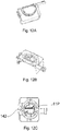
- FIGs. 12A - 12C there is shown the flow through fluid path 161 from the syringe molding to the reaction chamber 142.
- the flow through fluid path corresponds with port 11.
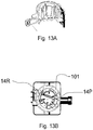
- FIG. 13A - 13B there is shown the reservoir insert 101 positioned such that port 14 is in-line with the syringe molding.
- Reservoir 14 is in communication with port 14.
- the fluid contained in reservoir 14 is pulled into the syringe molding.
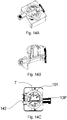
- the reservoir insert 101 then rotates to port 13 as shown in Figs. 14A - 14C .
- the fluid from reservoir 14 is then pushed through port 13 to the reaction chamber 142.
- the fluid passes through a channel that is distinct from the channel associated with port 11. This prevents fluids from coming in contact with and reacting with each other while in the channels.
- the fluids first come into contact in the reaction chamber 142.
- the plunger pushes the fluid from the reaction chamber 142 into the waste reservoir 7.
- the plunger draws the fluid back through port 11 and the reservoir insert rotates to a port in communication with waste reservoir 7.
- the plunger then pushes the fluid into the waste reservoir 7. It is understood that after use any reservoir can be utilized as a waste reservoir.
- the plunger stops pushing fluid once it reaches the reaction chamber 142.
- the plunger continues to push the fluid through the reaction chamber and into a port in communication with a waste reservoir or separate archive reservoir.
- An archive reservoir stores sample for additional testing or verification.
- FIGs. 15A - 15B there is shown the reservoir insert 101 positioned such that port 4 is in-line with the syringe molding. Port 4 is in communication with reservoir 4 containing a flush fluid. The flush fluid is drawn from reservoir 4 through port 4 and into the syringe molding. The reservoir insert 101 rotates to port 11 and the plunger pushes the flush fluid into port 11 and to the reaction chamber 142 as shown in Figs. 16A - 16C .
- the rotating valve can be removed and disposed. A fresh rotating valve with the same or unique fluids is then inserted into the detection device.
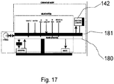
- FIG. 17 there is shown a schematic of a rotating valve of one embodiment.
- the reservoir insert contains six fluids in various reservoirs. Five fluids pass from their respective reservoirs into the syringe molding and through the main channel 180 into the reaction chamber 142. One fluid passes from the syringe molding through a secondary channel 181 and into the reaction chamber 142 to prevent any contamination or premature reactions.
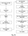
- Fig. 18 there is shown a process flow according to one embodiment. Once a sample is injected into the sample reservoir and the detection device is activated the testing begins. The channels are first preconditioned with a small amount of buffer. The sample is then transferred from the sample reservoir to the heating reservoir and heated at 95 °C for 5 minutes. The heated sample is then transferred to the reaction chamber to hybridize for 20 minutes. The hybridization process enables the sample to chemically bond with biological probes found on the chip in communication with the reaction chamber. The biological probes specifically bind to target nucleic acid molecules found in the sample as described in United States Patent Number 6,399,303 issued to Connolly on June 4, 2002 .
- a single chip may contain a plurality of distinct and redundant biological probes to increase sensitivity and to test for a variety of target nucleic acid molecules. It is further understood that the rotating valve can be used in any system requiring the manipulation and transport of a plurality of fluids.
- the sample is flushed with buffer to remove any excess compounds.
- a catalyst such as palladium is transferred to the reaction chamber and allowed to incubate for 10 minutes. The remaining catalyst is then flushed with water.
- a mixture of a reducing agent and metal, such as nickel, are pushed into the reaction chamber. The metal coats the target sample creating a conductor on the chip. The excess non-bonded metal is flushed with water.
- the resistance across biological probes bonded together by a target sample coated in metal dramatically reduces, indicating the presence of the target sample.
- the detection device writes the results of the test and the test is complete.
- Figs. 19A - 19B there is shown a variations of the reservoir insert.
- the chambers of the insert are shown in a rectangular configuration. Changes to the chamber sizes and shapes can be performed to optimize the particular reagent and waste chambers.
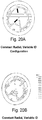
- Figs. 20A - 20B there are shown variations of the reservoir insert.
- the chambers of this embodiment are shown to have radial chambers.
- the chambers are of uniform size and shape around the radius of the insert.
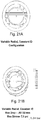
- Figs. 21A - 21B there are shown variations of the reservoir insert.
- the chambers are of various sizes along the radius of the insert to house differing amounts of reagents within each chamber. While variations of the insert are shown in the various embodiments, it is understood that any variation of the reservoir insert containing a plurality of ports and reservoirs can be used.
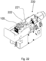
- a sampling device having a rotating valve drive and a plunger drive.
- the rotating valve 100 sets on top of the rotating valve drive.
- the plunger drive 220 contains a long cylindrical section 221 having a tip 220.
- the tip 220 connects to the plunger inside of the syringe molding 141.
- the tip 220 is conical improve contact with the plunger.
- the plunger drive moves the cylindrical section 221 axially causing the plunger to either pull or push fluids from the reservoirs in the rotating valve 100.
- FIG. 23 there is shown the rotating valve drive according to one embodiment.
- the rotating valve sets atop the contact surface 230.
- the contact surface 230 then rotates to position the reservoir insert to the desired location within the rotating valve.
- the contact surface 230 is part of a drive assembly 231.
- a worm gear 232 is attached to the drive assembly 231.
- a worm drive 233 engages the worm gear 232 causing the drive assembly 231 to rotate. It is understood that any suitable means to rotate the reservoir insert can be employed.
- Fig. 24 there is shown another view of the rotating valve drive.
- the worm drive 233 is a stepper motor positioned to advance the worm gear 232.
- a home flag 240 is attached to the drive assembly to zero the device. At any time during fluid sampling the home flag can be zeroed allowing the worm drive 233 to advance the appropriate distance.
- the contact surface having a heater.
- the contact surface is spring loaded to improve contact with the rotating valve.
- At least one spring 254 is positioned to allow movement of the contact surface.
- the contact surface contains a heater mount 250 to mount the heating elements.
- At least one resistor 251 is positioned on the heater mount 250.
- a heating plate 252 transfers heat from the resistors through the heating plate 252 and to the desired location on the rotating valve.
- the heating plate is an aluminum heating plate.
- a temperature sensor 253 is positioned near the resistor or heating plate to detect the applied temperature. It is understood that the contact surface (not shown) can be positioned over the heater plate.
- the contact surface is made from a material that allows an efficient thermal transfer from the heating plate to the rotating valve.
Landscapes
- Chemical & Material Sciences (AREA)
- Health & Medical Sciences (AREA)
- Clinical Laboratory Science (AREA)
- Chemical Kinetics & Catalysis (AREA)
- Engineering & Computer Science (AREA)
- General Engineering & Computer Science (AREA)
- Analytical Chemistry (AREA)
- Mechanical Engineering (AREA)
- Automatic Analysis And Handling Materials Therefor (AREA)
- Sampling And Sample Adjustment (AREA)
- Infusion, Injection, And Reservoir Apparatuses (AREA)
Description
- ] This application claims priority from
U.S. Provisional Patent Application Ser. No. 61/166,519, filed April 3, 2009 - ] The present invention relates to multi-chamber valves, and more particularly to multi-chamber rotating valves.
- ] Fluid analysis generally requires a series of process steps. Theses process steps generally require that distinct fluids contact a reaction area at different times and in varying secession. Furthermore, each fluid may require different pre-treatment prior to contacting the reaction area such as chemical, optical, thermal, mechanical, magnetic or acoustical pre-treatment steps. A single fluid sample may be subjected to a variety of pre-treatment steps prior to contact with a reaction area such as heating or ultrasonic processing. As the number of fluids and pre-treatment steps increase the more complex the fluid delivery system becomes.
- ]
US 6245233 B1 discloses a water filtering apparatus including a water container filled with filtering materials and a switch valve device.US 5133385 A discloses a changeover valve including a valve case, a valve body, and a control knob to rotate the valve body tto different positions.GB 701963 A DE 3712625 A1 discloses a connector including a housing with four nozzles, a valve nozzle, and a guide member.
Other relevant prior art are documentsUS 4889692 A andUS 2006/0177844 A .US 4889692 A discloses a carousel comprising a plurality of reservoirs able to be put into mutual fluid communication and filled by lowering a filling tube placed above it.
US 2006/0177844 A discloses a system for carrying out reactions including several reservoirs that can be put into fluid communication with a piston of a pump by means of a rotating valve. - ] Present designs for fluid delivery systems are customized for a particular process and are not easily converted to new processes. Generally, fluid delivery systems comprise a series of chambers uniquely configured for pre-treating and delivering a particular fluid. These systems are not easily adaptable to new pre-treatment steps or fluid delivery without changing both the chambers and delivery procedure. Therefore, there is a need for a fluid delivery system that is easily configurable to new delivery procedure and pre-treatment steps.
- ] Further, there is a need for a disposable fluid delivery system that can be easily inserted and removed from a bench-top or portable device.
- ] Yet further, there is a need for a fluid delivery system that is easily manufactured and customizable to suit varying fluid delivery needs.
- ] The present invention provides a multi-chamber rotating valve according to
claim 1. - Optional features of the invention are subject-matter of the dependent claims.
- ] The use of a rotating design allows for a single plunger to draw and push fluid samples without the need for a complex valve system to open and close at various times. This greatly reduces potential for leaks and failure of the device. Furthermore, the use of a plunger allows for greater configurability in adjusting the amount of fluid drawn.
- ] The reservoir insert is injected molded allowing for varied configurations with minimal costs. The exterior of the reservoir insert is cylindrical to allow free rotation about its axis when encased in the cartridge body. The interior section of the reservoir insert can be modified to include any size or shape reservoir or pre-treatment chamber.
- ] Customized rotating valves retain the same exterior shape and dimensions and can be inserted into existing equipment. The processing protocol of the instrument is easily modified to account for any new chambers, sample sizes, processing times, or port locations.
- ] The rotating valve can be stored in position leaving all ports and vents closed allowing for long-term storage and shipping of the rotating valve with liquid and solid reagents loaded within the valve.
- ] The present invention is disclosed with reference to the accompanying drawings, wherein:
-
Figs. 1A-1B show a graphical representation of a rotating valve according to one embodiment; -
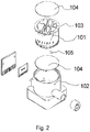
Fig. 2 shows an expanded view of a rotating valve according to one embodiment; -
Fig. 3A shows a cross-sectional view of a rotating valve according to one embodiment; -
Fig. 3B shows a cross-sectional view of a rotating valve according to one embodiment having an electromagnet and sonicator built into the valve; -
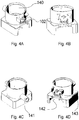
Figs. 4A-4D show a graphical representation of the cartridge body according to one embodiment; -
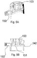
Figs. 5A-5B show a cross-sectional view of an assembled rotating valve according to one embodiment having the multi-chamber reservoir secured in the cartridge body. -
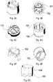
Figs. 6A-6G show a graphical representation of the multi-chamber reservoir according to one embodiment; -
Figs. 7-16C show various graphical representations of an assembled rotating valve with the multi-chamber reservoir positioned for desired fluid flow through the channels according to one embodiment; -
Fig. 17 shows a schematic representation of the rotating valve according to one embodiment; -
Fig. 18 shows a process flow chart for one use of the rotating valve according to one embodiment; -
Figs. 19A-19B show a graphical representation of multi-chamber reservoir insert configurations according to an alternative embodiment; -
Figs. 20A-20B show a graphical representation of multi-chamber reservoir insert configurations according to an alternative embodiment; -
Figs. 21A-21B show a graphical representation of multi-chamber reservoir insert configurations according to an alternative embodiment; -
Fig. 22 shows a graphical representation of sampling device containing a rotating valve drive and plunger drive according to one embodiment; -
Fig. 23 shows a graphical representation of a rotating valve drive with the rotating valve removed according to one embodiment; -
Fig. 24 shows a graphical representation of the stepper motor assembly and worm drive according to one embodiment; and -
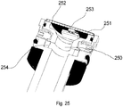
Fig. 25 shows a graphical representation of a the heater according to one embodiment. - ] Corresponding reference characters indicate corresponding parts throughout the several views. The examples set out herein illustrate several embodiments of the invention but should not be construed as limiting the scope of the invention in any manner.
- ] The rotating valve of the instant invention is a two piece construction capable of various positioning to allow the passage of fluid contained in the reservoirs into the fluid paths. The two piece design allows for easy manufacturing and assembly. The design further allows for the rotating valve to be a disposable piece in instruments requiring a plurality of fluids. In one embodiment, the rotating valve is a single use piece for use in detection devices. The rotating valve contains the necessary fluids for biological testing and further is capable of being injected with a field sample.
- ] Referring to
Figs. 1A - 1B there is shown an assembled rotating valve of the instant invention. The rotating valve comprises two main components. Thereservoir insert 101 is contained within thecartridge body 102. Therotating valve 100 is a disposable component containing a plurality reservoirs capable of storing a plurality of fluids. In one embodiment, thereservoir insert 101 and thecartridge body 102 are both formed through injection molding techniques. - ] In one embodiment a chip containing biological probes is affixed to the
cartridge body 102. The fluid contained in the reservoirs is transferred to contact the chip containing biological probes initiating reaction or detection chemistry. The chip is in communication with a detection device such as a bench-top or portable detection device to indicate the presence of target biological probes in any sample. Therotating valve 100 is inserted into a detection device that is in electrical communication with the chip. The detection device further affixes thecartridge body 102 into a fixed position. - ] Referring to
Fig. 2 there is shown an exploded view of the instant invention. Thereservoir insert 101 is capable of containing a plurality of fluids in thevarious reservoirs 103. Theheat seal films 104 seal the fluids into the reservoir insert and prevent leaks while allowing for the injection of samples. Theheat seal films 104 seal the reservoirs from the outside environment. Theheat seal films 104 further allow for fluid to be added to or removed from the reservoirs without compromising the integrity of the seal. In one embodiment, theheat seal films 104 improve energy transfer into and out of the reservoirs and chambers of thereservoir insert 101. Energy transfer includes but is not limited to heat, ultrasonic and magnetic. Optionally, afilter 105 is placed in-line with particular fluid paths to filter large solids from the fluid. In one embodiment Once theheat seal films 104 are sealed onto thereservoir insert 101 thereservoir insert 101 is affixed to thecartridge body 102. In one embodiment, thereservoir insert 101 "snaps into" thecartridge body 102. It is understood that theheat seal films 104 can be sealed to thereservoir insert 101 after thereservoir insert 101 is affixed to thecartridge body 102. - ] Referring now to
Figs. 3A - 3B there is shown a cross sectional view of therotating valve 100. Therotating valve 100 is set onto adrive mechanism 110. Thedrive mechanism 110 is capable of rotating thereservoir insert 101 to the desired configuration. Thedrive mechanism 110 rotates thereservoir insert 101 while thecartridge body 102 remains stationary. In one embodiment the drive mechanism has anoptional heater 111. The heater is capable of heating the fluids contained in thereservoirs 103 to the desired temperature. Alternatively, heating chambers are strategically positioned above the heater to heat the fluid in the chamber without significantly heating the fluids in thereservoirs 103. In one embodiment, the heat film seals 104 facilitate this heating without significantly heating the fluids in thereservoirs 103. Treatment chambers are incorporated into thereservoir insert 101 to facilitate mixing, heating, disrupting, pressurization or any other treatment process. - ] In one embodiment the drive mechanism has a
disruptor 112. The disruptor is capable of mixing or breaking down the fluids contained in thereservoirs 103 by applying an ultrasonic force. Alternatively, the rotating valve has a disruptingchamber 113 for mixing fluids in a chamber distinct from the reservoirs. In one embodiment small beads are located in the disrupting chamber or reservoir to assist in mixing fluids or breaking down samples. Thedisrupter 112 applies an ultrasonic force causing the beads to become excited and move through the fluid. In one embodiment amagnet 114 is utilized to generate an electric field. The magnet can pull or push magnetic particles in the reservoir insert. Themagnet 114 can concentrate a sample of magnetic particles or speed up the diffusion process by guiding any magnetic particles. - ] Referring to
Figs. 4A - 4D there are shown various views of one embodiment of thecartridge body 102. It is understood that various designs can be used to house the reservoir insert. Thecartridge body 102 has an innercylindrical surface 140. The innercylindrical surface 140 houses the reservoir insert (not shown). The innercylindrical surface 140 is smooth to allow the reservoir insert to freely rotate. The cartridge body is constructed from any material that is both ridged enough to support the cartridge body and smooth enough to allow for rotation of the reservoir insert. In one embodiment, the innercylindrical surface 140 has a slight taper to facilitate attachment of the reservoir insert (not shown) having an outer cylindrical surface with a slight taper. - ] The cartridge body has a
syringe molding 141 formed, as depicted, as a syringe barrel. Although only one syringe is shown it is understood that a plurality of syringes can be used. Thesyringe molding 141 houses a plunger. The plunger draws and pushes fluids through the reservoir inserts fluid paths. The plunger 144 is retained within thesyringe molding 141. Optionally, the cartridge body has areaction chamber 142 andsensor mount 143. Thesensor mount 143 is capable of holding a sensor board. The sensor board is aligned to thesensor mount 143 by the alignment posts 146. The plunger delivers fluids through the fluid paths and to thereaction chamber 142. The fluids chemically react with other fluids or devices in communication with thereaction chamber 142. It is understood that a fluid output can be attached to the cartridge body to allow the fluid to transfer from the rotating valve to a desired location. Furthermore, a fluid input allows the introduction of fluids to the rotating valve. - ] In one embodiment the sensor board contains a chip having a reactive surface. The chip is positioned such that it is in communication with the
reaction chamber 142. In one embodiment the chip forms one side of thereaction chamber 142. Fluid flows into thereaction chamber 142 and contacts the reactive surface of the chip (not shown). The chip is in electrical communication with a detection device to provide readings and results of the testing. - ] Referring to
Figs. 5A - 5B there is shown a cross sectional view of an assembled rotating valve having aplunger 150. Theplunger 150 is capable of drawing fluid from thereservoirs 103. Once theplunger 150 draws the fluid, the rotating valve repositions the fluid path to align a distinct port with the syringe molding. Theplunger 150 then pushes the fluid through thefluid path 151 into thereaction chamber 142, a different reservoir, or a pre-treatment chamber. - ] Referring to
Figs. 6A -6G there are shown multiple views of the reservoir insert. The reservoir insert has an outer cylindrical surface 106. In one embodiment the outer cylindrical surface 106 is tapered. The reservoir insert containsmultiple reservoirs 103. Thereservoirs 103 can contain samples, standards, wash, catalyst or any other desirable fluid. In one embodiment thereservoirs 103 include a waste reservoir to discharge fluids. The reservoir insert further containsmultiple ports 160. Eachport 160 has a unique fluid path. Each chamber and reservoir has a fluid path that is in communication with a port to transfer fluid to or from the chamber or reservoir. A syringe molding on the cartridge body (not shown) lines up with a port to extract or push fluid. To prevent pressure differentials from formingpressure relief ports 164 are positioned along the reservoir insert. In addition to the unique fluid paths, the reservoir insert contains at least one fluid throughchannel 161. The fluid throughchannel 161 allows for the fluid to flow from the one end of the reservoir insert to the other. For example, the fluid can flow from the syringe molding to the reaction chamber of the cartridge body (not shown). - ] To prevent fluid interaction in the fluid through channel 161 a plurality of fluid through channels are used. The secondary fluid through
channel 162 is used to prevent early reactions or other adverse fluid interactions. In one embodiment the reservoir insert contains aheater contact region 163. The heater contact region is positioned below the reservoirs for which it is desirable to heat the fluid in the reservoir. Furthermore, the heater is capable of heating the fluid throughchannel 161. - ] Referring to
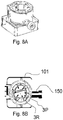
Figs. 7A - 16C there are shown multiple of views of an assembled rotating valve rotated in various positions. As shown inFigs. 7A - 7B thereservoir insert 101 is in a closed position. No ports are in line with the syringe molding (not shown). This prevents any leakage of fluid from the reservoir. In one embodiment at least one reservoir is a sample reservoir. The sample reservoir enables the user to inject a fluid sample into the reservoir through the heat film seal. In one embodiment the sample reservoir contains disrupting objects, such as glass beads, to assist in breaking down samples into testable nucleic acid strands. - ] Referring to
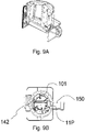
Figs. 8A - 8B thereservoir insert 101 is positioned such that port 3 is in-line with the syringe molding. Once positioned fluid from reservoir 3 can be drawn through port 3 and into thesyringe molding 141. Once fluid is pulled from a reservoir, and no additional fluid is required from that reservoir, that reservoir can be used as an alternative reservoir for waste storage. Referring toFigs. 9A - 9B , thereservoir insert 101 is positioned such that port 11 is in-line with the syringe molding. The plunger pushes the fluid drawn from reservoir 3 into port 11 and the fluid passes to thereaction chamber 142. - ] Referring to
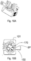
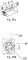
Figs. 10A-10B thereservoir insert 101 is positioned such that port 8 is in-line with the syringe molding. In one embodiment fluid is pushed from thesyringe molding 141 into port 8 and into a heating chamber. Once in theheating chamber 170 the fluid is heated at the desired temperature for a predetermined amount of time. Once the heating has completed the fluid is drawn back into the syringe molding. It is understood that the fluid may be drawn through the same port 8 or unique port in communication with the heating chamber. As shown inFigs. 11A-11B the fluid is drawn into the syringe molding from a unique port 9 in communication with theheating chamber 170. - ] Referring now to
Figs. 12A - 12C there is shown the flow throughfluid path 161 from the syringe molding to thereaction chamber 142. In this embodiment the flow through fluid path corresponds with port 11. - ] Referring to
Figs. 13A - 13B there is shown thereservoir insert 101 positioned such that port 14 is in-line with the syringe molding. Reservoir 14 is in communication with port 14. The fluid contained in reservoir 14 is pulled into the syringe molding. Thereservoir insert 101 then rotates to port 13 as shown inFigs. 14A - 14C . The fluid from reservoir 14 is then pushed throughport 13 to thereaction chamber 142. The fluid passes through a channel that is distinct from the channel associated with port 11. This prevents fluids from coming in contact with and reacting with each other while in the channels. The fluids first come into contact in thereaction chamber 142. - ] After the desired reaction time the plunger pushes the fluid from the
reaction chamber 142 into thewaste reservoir 7. The plunger draws the fluid back through port 11 and the reservoir insert rotates to a port in communication withwaste reservoir 7. The plunger then pushes the fluid into thewaste reservoir 7. It is understood that after use any reservoir can be utilized as a waste reservoir. In an alternative embodiment, the plunger stops pushing fluid once it reaches thereaction chamber 142. Upon completion of the reaction time, the plunger continues to push the fluid through the reaction chamber and into a port in communication with a waste reservoir or separate archive reservoir. An archive reservoir stores sample for additional testing or verification. - ] Referring to
Figs. 15A - 15B there is shown thereservoir insert 101 positioned such thatport 4 is in-line with thesyringe molding. Port 4 is in communication withreservoir 4 containing a flush fluid. The flush fluid is drawn fromreservoir 4 throughport 4 and into the syringe molding. Thereservoir insert 101 rotates to port 11 and the plunger pushes the flush fluid into port 11 and to thereaction chamber 142 as shown inFigs. 16A - 16C . - ] Once completed the rotating valve can be removed and disposed. A fresh rotating valve with the same or unique fluids is then inserted into the detection device.
- ] Referring to
Fig. 17 there is shown a schematic of a rotating valve of one embodiment. The reservoir insert contains six fluids in various reservoirs. Five fluids pass from their respective reservoirs into the syringe molding and through themain channel 180 into thereaction chamber 142. One fluid passes from the syringe molding through asecondary channel 181 and into thereaction chamber 142 to prevent any contamination or premature reactions. - ] Referring to
Fig. 18 there is shown a process flow according to one embodiment. Once a sample is injected into the sample reservoir and the detection device is activated the testing begins. The channels are first preconditioned with a small amount of buffer. The sample is then transferred from the sample reservoir to the heating reservoir and heated at 95 °C for 5 minutes. The heated sample is then transferred to the reaction chamber to hybridize for 20 minutes. The hybridization process enables the sample to chemically bond with biological probes found on the chip in communication with the reaction chamber. The biological probes specifically bind to target nucleic acid molecules found in the sample as described in United States Patent Number6,399,303 issued to Connolly on June 4, 2002 . It is understood that a single chip may contain a plurality of distinct and redundant biological probes to increase sensitivity and to test for a variety of target nucleic acid molecules. It is further understood that the rotating valve can be used in any system requiring the manipulation and transport of a plurality of fluids. - ] After hybridization the sample is flushed with buffer to remove any excess compounds. Optionally a catalyst such as palladium is transferred to the reaction chamber and allowed to incubate for 10 minutes. The remaining catalyst is then flushed with water. A mixture of a reducing agent and metal, such as nickel, are pushed into the reaction chamber. The metal coats the target sample creating a conductor on the chip. The excess non-bonded metal is flushed with water. The resistance across biological probes bonded together by a target sample coated in metal dramatically reduces, indicating the presence of the target sample. The detection device writes the results of the test and the test is complete.
- ] Referring now to
Figs. 19A - 19B there is shown a variations of the reservoir insert. The chambers of the insert are shown in a rectangular configuration. Changes to the chamber sizes and shapes can be performed to optimize the particular reagent and waste chambers. - ] Referring now to
Figs. 20A - 20B there are shown variations of the reservoir insert. The chambers of this embodiment are shown to have radial chambers. In one embodiment the chambers are of uniform size and shape around the radius of the insert. - ] Referring now to
Figs. 21A - 21B there are shown variations of the reservoir insert. The chambers are of various sizes along the radius of the insert to house differing amounts of reagents within each chamber. While variations of the insert are shown in the various embodiments, it is understood that any variation of the reservoir insert containing a plurality of ports and reservoirs can be used. - ] Referring to
Fig. 22 there is shown a sampling device having a rotating valve drive and a plunger drive. Therotating valve 100 sets on top of the rotating valve drive. Theplunger drive 220 contains a longcylindrical section 221 having atip 220. Thetip 220 connects to the plunger inside of thesyringe molding 141. In one embodiment thetip 220 is conical improve contact with the plunger. The plunger drive moves thecylindrical section 221 axially causing the plunger to either pull or push fluids from the reservoirs in therotating valve 100. - ] Referring to
Fig. 23 there is shown the rotating valve drive according to one embodiment. The rotating valve sets atop thecontact surface 230. Thecontact surface 230 then rotates to position the reservoir insert to the desired location within the rotating valve. In one embodiment thecontact surface 230 is part of adrive assembly 231. Aworm gear 232 is attached to thedrive assembly 231. Aworm drive 233 engages theworm gear 232 causing thedrive assembly 231 to rotate. It is understood that any suitable means to rotate the reservoir insert can be employed. - ] Referring to
Fig. 24 there is shown another view of the rotating valve drive. Theworm drive 233 is a stepper motor positioned to advance theworm gear 232. Ahome flag 240 is attached to the drive assembly to zero the device. At any time during fluid sampling the home flag can be zeroed allowing theworm drive 233 to advance the appropriate distance. - ] Referring to
Fig. 25 there is shown the contact surface having a heater. The contact surface is spring loaded to improve contact with the rotating valve. At least onespring 254 is positioned to allow movement of the contact surface. In one embodiment the contact surface contains aheater mount 250 to mount the heating elements. At least oneresistor 251 is positioned on theheater mount 250. Aheating plate 252 transfers heat from the resistors through theheating plate 252 and to the desired location on the rotating valve. In one embodiment the heating plate is an aluminum heating plate. Optionally, atemperature sensor 253 is positioned near the resistor or heating plate to detect the applied temperature. It is understood that the contact surface (not shown) can be positioned over the heater plate. The contact surface is made from a material that allows an efficient thermal transfer from the heating plate to the rotating valve. - ] While the invention has been described with reference to particular embodiments, it will be understood by those skilled in the art that various changes may be made and equivalents may be substituted for elements thereof without departing from the scope of the invention. In addition, many modifications may be made to adapt a particular situation or material to the teachings of the invention without departing from the scope of the invention.
- ] Therefore, it is intended that the invention not be limited to the particular embodiments disclosed as the best mode contemplated for carrying out this invention, but that the invention will include all embodiments falling within the scope of the appended claims.
Claims (10)
- A multi-chamber rotating valve (100) comprising:a cartridge housing (102) including a fluid delivery device (141); anda reservoir insert (101) affixed to, and rotating about an axis relative to, the cartridge housing (102);wherein the reservoir insert (101) comprises: a plurality of reservoirs (103); a plurality of ports (160); and at least one fluid channel (161) in communication with at least one reservoir (103) and at least one port (160),wherein the fluid delivery device (141) is a syringe barrel defining a syringe port and a barrel plunger (150) disposed within the syringe barrel, the barrel plunger configured to effect flow of an assay fluid through the syringe port and into one of the reservoirs (103) of the reservoir insert (101), andwherein said reservoir insert (101) rotates to align at least one port (160) of the reservoir insert (101) with the syringe port of the fluid delivery device (141).
- The multi-chamber rotating valve (100) of claim 1, wherein said reservoir insert (101) further comprises a fluid flowing through channel in communication with the at least one port and an output port.
- The multi-chamber rotating valve (100) of claim 2, wherein said cartridge housing (102) further comprises a reaction chamber (142).
- The multi-chamber rotating valve (100) of claim 3, wherein said output port is in communication with the reaction chamber (142).
- The multi-chamber rotating valve (100) of claim 1, wherein said reservoir insert (101) further comprises a film seal (104) to retain fluids within the plurality of reservoirs (103).
- The multi-chamber rotating valve (100) of claim 5, wherein the fluid delivery device is an output port capable of connection to an external fluid delivery device.
- The multi-chamber rotating valve (100) of claim 2, wherein said cartridge housing (102) further comprises a chip having biological microprobes.
- The multi-chamber rotating valve (100) of claim 7, wherein said chip having biological microprobes is in communication with the reaction chamber (142) and forms a wall of the reaction chamber (142).
- The multi-chamber rotating valve (100) of claim 6, wherein the syringe barrel (150) defines an elongate axis which is radially oriented relative to the rotational axis of the reservoir insert (101).
- The multi-chamber rotating valve (100) of claim 6, wherein the plunger displaces assay fluids into and out of the reservoirs (103) as the plunger is displaced toward and away from the reservoir insert (101).
Applications Claiming Priority (2)
| Application Number | Priority Date | Filing Date | Title |
|---|---|---|---|
| US16651909P | 2009-04-03 | 2009-04-03 | |
| PCT/US2010/029961 WO2010115192A2 (en) | 2009-04-03 | 2010-04-05 | Multi-chamber rotating valve |
Publications (3)
| Publication Number | Publication Date |
|---|---|
| EP2414710A2 EP2414710A2 (en) | 2012-02-08 |
| EP2414710A4 EP2414710A4 (en) | 2017-09-20 |
| EP2414710B1 true EP2414710B1 (en) | 2019-03-20 |
Family
ID=42825184
Family Applications (1)
| Application Number | Title | Priority Date | Filing Date |
|---|---|---|---|
| EP10759538.1A Not-in-force EP2414710B1 (en) | 2009-04-03 | 2010-04-05 | Multi-chamber rotating valve |
Country Status (6)
| Country | Link |
|---|---|
| US (1) | US8716006B2 (en) |
| EP (1) | EP2414710B1 (en) |
| JP (1) | JP5450788B2 (en) |
| AU (1) | AU2010232396B2 (en) |
| CA (1) | CA2757597C (en) |
| WO (1) | WO2010115192A2 (en) |
Families Citing this family (22)
| Publication number | Priority date | Publication date | Assignee | Title |
|---|---|---|---|---|
| US9347086B2 (en) | 2009-04-03 | 2016-05-24 | Integrated Nano-Technologies, Llc | Method and system for sample preparation |
| CA2888316C (en) * | 2012-10-17 | 2021-05-04 | Integrated Nano-Technologies, Llc | Method and system for sample preparation |
| CZ304743B6 (en) * | 2013-01-18 | 2014-09-17 | Wolf & Danniel S.R.O. | Means for isolation of nucleic acids and method carried out by means of the means |
| CA2900215A1 (en) * | 2013-03-15 | 2014-09-18 | Illumina, Inc. | System and method for generating or analyzing a biological sample |
| US9880159B2 (en) * | 2014-10-01 | 2018-01-30 | Linda S. Powers | Cartridge-based detection system |
| US9970437B2 (en) | 2014-11-25 | 2018-05-15 | Genia Technologies, Inc. | Two-way pump selectable valve and bypass waste channel |
| HK1247987A1 (en) * | 2015-04-02 | 2018-10-05 | 塞弗德公司 | Fluidic bridge device and sample processing methods |
| EP3098606A1 (en) * | 2015-05-29 | 2016-11-30 | Roche Diagniostics GmbH | Cartridge for dispensing particles and a reagent fluid |
| CN105135051B (en) * | 2015-09-30 | 2019-06-18 | 博奥生物集团有限公司 | A microfluidic valve and microfluidic chip |
| BR112018008629B1 (en) | 2015-11-04 | 2020-11-17 | Nitto Denko Corporation | apparatus for testing a biofluid, apparatus for containing and dispensing biofluid samples and a system for dispensing and testing biofluid |
| EP3458862B1 (en) | 2016-05-17 | 2020-04-22 | Integrated Nano-Technologies, Inc. | Disposable cartridge with filtration column assembly for diagnostic assay system |
| WO2017223027A1 (en) * | 2016-06-20 | 2017-12-28 | Integrated Nano-Technologies, Inc. | Multiple rotor disposable cartridge for portable diagnostic assay system |
| US10737267B2 (en) | 2017-04-04 | 2020-08-11 | Omniome, Inc. | Fluidic apparatus and methods useful for chemical and biological reactions |
| KR102263976B1 (en) * | 2017-12-15 | 2021-06-14 | 프리시젼바이오 주식회사 | Diagnostic System |
| JP6876010B2 (en) * | 2018-01-31 | 2021-05-26 | 株式会社エンプラス | Containment unit and fluid handling device |
| WO2019163747A1 (en) * | 2018-02-20 | 2019-08-29 | 株式会社エンプラス | Fluid handling device and die |
| JP7187342B2 (en) * | 2018-02-20 | 2022-12-12 | 株式会社エンプラス | Fluid handling equipment and molds |
| GB201806505D0 (en) | 2018-04-20 | 2018-06-06 | Q Linea Ab | Analysis instrument and sample preparation cartridge |
| US12029397B2 (en) | 2019-09-23 | 2024-07-09 | Spectrum Solutions L.L.C. | Sample collection kit including cap having selectively openable diaphragm valve |
| CN116139954B (en) * | 2023-02-20 | 2023-08-22 | 首都医科大学 | Microfluidic chip for multichannel isothermal amplification CRISPR detection |
| CN116532174A (en) * | 2023-06-21 | 2023-08-04 | 北京保利微芯科技有限公司 | Microfluidic chip with rotary valve and control method thereof |
| WO2025193617A1 (en) * | 2024-03-11 | 2025-09-18 | Biological Mimetics, Inc. | Multi-chamber devices for detecting pathogens/molecules and methods of using same |
Citations (2)
| Publication number | Priority date | Publication date | Assignee | Title |
|---|---|---|---|---|
| US4889692A (en) * | 1984-11-05 | 1989-12-26 | Holtzman Marc E | Disposable sample preparation container |
| US20060177844A1 (en) * | 2004-10-27 | 2006-08-10 | Cepheid | Closed-system multi-stage nucleic acid amplification reactions |
Family Cites Families (20)
| Publication number | Priority date | Publication date | Assignee | Title |
|---|---|---|---|---|
| GB701963A (en) | 1949-01-26 | 1954-01-06 | Joseph Ingleby Owens | Improvements relating to fluid pressure distributing apparatus and applications thereof |
| US4068528A (en) * | 1976-01-19 | 1978-01-17 | Rheodyne Incorporated | Two position rotary valve for injecting sample liquids into an analysis system |
| EP0179129B1 (en) * | 1984-04-11 | 1990-03-21 | Arden Medical Systems, Inc. | Self-calibrating single-use sensing device for clinical chemistry analyzer |
| US4702889A (en) | 1986-01-16 | 1987-10-27 | Coulter Electronics Inc. | Liquid sampling valve |
| DE3712625A1 (en) | 1987-04-14 | 1988-11-03 | Danfoss As | Connection fitting for radiators |
| US5105851A (en) * | 1990-10-17 | 1992-04-21 | Hewlett-Packard Company | Apparatus for multi-path flow regulation |
| JP2523223B2 (en) | 1990-11-30 | 1996-08-07 | けい子 川上 | Switching valve device for filters |
| JP2589997Y2 (en) | 1993-02-17 | 1999-02-03 | シスメックス株式会社 | Sampling valve |
| US5558838A (en) * | 1993-09-29 | 1996-09-24 | Becton Dickinson And Company | Sample preparation apparatus |
| US6129828A (en) * | 1996-09-06 | 2000-10-10 | Nanogen, Inc. | Apparatus and methods for active biological sample preparation |
| US6245233B1 (en) | 1997-11-26 | 2001-06-12 | Chih Wen Lu | Water filtering apparatus with water flow switch valve device |
| US6387710B1 (en) | 1998-11-04 | 2002-05-14 | Sarnoff Corporation | Automated sample processor |
| US6374684B1 (en) * | 2000-08-25 | 2002-04-23 | Cepheid | Fluid control and processing system |
| US6769573B1 (en) * | 2002-09-13 | 2004-08-03 | Randal N. Kazarian | Multi-chambered container fluid selection valve |
| EP1578995A2 (en) * | 2002-11-18 | 2005-09-28 | Agency for Science, Technology and Research | Method and system for cell and/or nucleic acid molecules isolation |
| US20040157343A1 (en) * | 2003-02-06 | 2004-08-12 | Applera Corporation | Devices and methods for biological sample preparation |
| WO2005111210A1 (en) * | 2004-05-18 | 2005-11-24 | Fujifilm Corporation | Method for extracting nucleic acid and nucleic acid-extracting apparatus |
| AU2005323451B2 (en) * | 2004-05-21 | 2010-11-18 | Qiagen Sciences Llc | Kits and processes for removing contaminants from nucleic acids in environmental and biological samples |
| US20080113357A1 (en) * | 2006-06-29 | 2008-05-15 | Millipore Corporation | Filter device for the isolation of a nucleic acid |
| US8230774B1 (en) * | 2008-01-11 | 2012-07-31 | Hunte Karen A | Multi-unit bottle preparation device |
-
2010
- 2010-04-05 WO PCT/US2010/029961 patent/WO2010115192A2/en not_active Ceased
- 2010-04-05 JP JP2012503770A patent/JP5450788B2/en not_active Expired - Fee Related
- 2010-04-05 EP EP10759538.1A patent/EP2414710B1/en not_active Not-in-force
- 2010-04-05 CA CA2757597A patent/CA2757597C/en active Active
- 2010-04-05 US US12/754,205 patent/US8716006B2/en active Active
- 2010-04-05 AU AU2010232396A patent/AU2010232396B2/en not_active Ceased
Patent Citations (2)
| Publication number | Priority date | Publication date | Assignee | Title |
|---|---|---|---|---|
| US4889692A (en) * | 1984-11-05 | 1989-12-26 | Holtzman Marc E | Disposable sample preparation container |
| US20060177844A1 (en) * | 2004-10-27 | 2006-08-10 | Cepheid | Closed-system multi-stage nucleic acid amplification reactions |
Also Published As
| Publication number | Publication date |
|---|---|
| CA2757597A1 (en) | 2010-10-07 |
| AU2010232396A1 (en) | 2011-10-27 |
| JP5450788B2 (en) | 2014-03-26 |
| WO2010115192A2 (en) | 2010-10-07 |
| US20100252116A1 (en) | 2010-10-07 |
| EP2414710A4 (en) | 2017-09-20 |
| CA2757597C (en) | 2017-08-29 |
| WO2010115192A3 (en) | 2011-01-20 |
| EP2414710A2 (en) | 2012-02-08 |
| JP2012522996A (en) | 2012-09-27 |
| US8716006B2 (en) | 2014-05-06 |
| AU2010232396B2 (en) | 2014-03-20 |
Similar Documents
| Publication | Publication Date | Title |
|---|---|---|
| CA2757597C (en) | Multi-chamber rotating valve | |
| EP2310128B1 (en) | Device for analysing a chemical or biological sample | |
| CN107429281B (en) | Devices and methods for molecular diagnostic testing | |
| CN104412075B (en) | cartridges for dispensing fluids | |
| US10527192B2 (en) | Rotary valve | |
| CN107619785B (en) | Fluid Integration Module | |
| US20060235335A1 (en) | Device having a self sealing fluid port | |
| US20100135853A1 (en) | Automatic isothermal titration microcalorimeter apparatus and method of use | |
| EP3523035B1 (en) | Analysis device and method for testing a sample | |
| US20100255483A1 (en) | Liquid-feeding chip and analysis method | |
| EP1681552A2 (en) | Chemical analysis device and chemical analysis cartridge | |
| US20070048194A1 (en) | Use of a disposable container, microfluidic device and method for processing molecules | |
| JP2009109459A (en) | Pipette chip, inspection system, pipette, and filling apparatus | |
| EP1710016A2 (en) | Device having a self sealing fluid port | |
| JP2011163946A (en) | Microfluid chip | |
| JP2022545830A (en) | Filter Devices, Kits, and Methods of Pretreating Samples | |
| EP4180125A1 (en) | System for providing fluids in microfluidic products | |
| US20170157612A1 (en) | Reagent storage device and bio-reaction apparatus including the same | |
| EP3600669A1 (en) | Sample pre-treatment devices and methods |
Legal Events
| Date | Code | Title | Description |
|---|---|---|---|
| PUAI | Public reference made under article 153(3) epc to a published international application that has entered the european phase |
Free format text: ORIGINAL CODE: 0009012 |
|
| 17P | Request for examination filed |
Effective date: 20111004 |
|
| AK | Designated contracting states |
Kind code of ref document: A2 Designated state(s): AT BE BG CH CY CZ DE DK EE ES FI FR GB GR HR HU IE IS IT LI LT LU LV MC MK MT NL NO PL PT RO SE SI SK SM TR |
|
| DAX | Request for extension of the european patent (deleted) | ||
| RAP1 | Party data changed (applicant data changed or rights of an application transferred) |
Owner name: INTEGRATED NANO-TECHNOLOGIES LLC |
|
| A4 | Supplementary search report drawn up and despatched |
Effective date: 20170821 |
|
| RIC1 | Information provided on ipc code assigned before grant |
Ipc: B67D 7/64 20100101ALI20170814BHEP Ipc: B67D 7/80 20100101ALI20170814BHEP Ipc: F16K 5/04 20060101AFI20170814BHEP Ipc: G01N 27/00 20060101ALI20170814BHEP Ipc: B67D 7/02 20100101ALI20170814BHEP |
|
| RIN1 | Information on inventor provided before grant (corrected) |
Inventor name: CONNOLLY, DENNIS, M. Inventor name: MURANTE, RICHARD, S. Inventor name: KILCOIN, CHRISTOPHER Inventor name: APTEKAREV, KONSTANTIN |
|
| REG | Reference to a national code |
Ref country code: DE Ref legal event code: R079 Ref document number: 602010057684 Country of ref document: DE Free format text: PREVIOUS MAIN CLASS: F16K0005040000 Ipc: G01N0035100000 |
|
| GRAP | Despatch of communication of intention to grant a patent |
Free format text: ORIGINAL CODE: EPIDOSNIGR1 |
|
| STAA | Information on the status of an ep patent application or granted ep patent |
Free format text: STATUS: GRANT OF PATENT IS INTENDED |
|
| RIC1 | Information provided on ipc code assigned before grant |
Ipc: F16K 11/085 20060101ALI20180910BHEP Ipc: B01L 3/00 20060101ALI20180910BHEP Ipc: G01N 35/10 20060101AFI20180910BHEP Ipc: B01L 3/02 20060101ALI20180910BHEP |
|
| INTG | Intention to grant announced |
Effective date: 20181011 |
|
| GRAS | Grant fee paid |
Free format text: ORIGINAL CODE: EPIDOSNIGR3 |
|
| GRAA | (expected) grant |
Free format text: ORIGINAL CODE: 0009210 |
|
| STAA | Information on the status of an ep patent application or granted ep patent |
Free format text: STATUS: THE PATENT HAS BEEN GRANTED |
|
| RIN1 | Information on inventor provided before grant (corrected) |
Inventor name: KILCOIN, CHRISTOPHER Inventor name: APTEKAREV, KONSTANTIN Inventor name: MURANTE, RICHARD, S. Inventor name: WESCOTT, NATHANIEL E. Inventor name: CONNOLLY, DENNIS, M. |
|
| AK | Designated contracting states |
Kind code of ref document: B1 Designated state(s): AT BE BG CH CY CZ DE DK EE ES FI FR GB GR HR HU IE IS IT LI LT LU LV MC MK MT NL NO PL PT RO SE SI SK SM TR |
|
| REG | Reference to a national code |
Ref country code: GB Ref legal event code: FG4D |
|
| REG | Reference to a national code |
Ref country code: CH Ref legal event code: EP |
|
| REG | Reference to a national code |
Ref country code: DE Ref legal event code: R096 Ref document number: 602010057684 Country of ref document: DE |
|
| REG | Reference to a national code |
Ref country code: AT Ref legal event code: REF Ref document number: 1111076 Country of ref document: AT Kind code of ref document: T Effective date: 20190415 |
|
| REG | Reference to a national code |
Ref country code: IE Ref legal event code: FG4D |
|
| REG | Reference to a national code |
Ref country code: NL Ref legal event code: FP |
|
| PG25 | Lapsed in a contracting state [announced via postgrant information from national office to epo] |
Ref country code: NO Free format text: LAPSE BECAUSE OF FAILURE TO SUBMIT A TRANSLATION OF THE DESCRIPTION OR TO PAY THE FEE WITHIN THE PRESCRIBED TIME-LIMIT Effective date: 20190620 Ref country code: LT Free format text: LAPSE BECAUSE OF FAILURE TO SUBMIT A TRANSLATION OF THE DESCRIPTION OR TO PAY THE FEE WITHIN THE PRESCRIBED TIME-LIMIT Effective date: 20190320 Ref country code: SE Free format text: LAPSE BECAUSE OF FAILURE TO SUBMIT A TRANSLATION OF THE DESCRIPTION OR TO PAY THE FEE WITHIN THE PRESCRIBED TIME-LIMIT Effective date: 20190320 Ref country code: FI Free format text: LAPSE BECAUSE OF FAILURE TO SUBMIT A TRANSLATION OF THE DESCRIPTION OR TO PAY THE FEE WITHIN THE PRESCRIBED TIME-LIMIT Effective date: 20190320 |
|
| REG | Reference to a national code |
Ref country code: LT Ref legal event code: MG4D |
|
| PG25 | Lapsed in a contracting state [announced via postgrant information from national office to epo] |
Ref country code: LV Free format text: LAPSE BECAUSE OF FAILURE TO SUBMIT A TRANSLATION OF THE DESCRIPTION OR TO PAY THE FEE WITHIN THE PRESCRIBED TIME-LIMIT Effective date: 20190320 Ref country code: HR Free format text: LAPSE BECAUSE OF FAILURE TO SUBMIT A TRANSLATION OF THE DESCRIPTION OR TO PAY THE FEE WITHIN THE PRESCRIBED TIME-LIMIT Effective date: 20190320 Ref country code: BG Free format text: LAPSE BECAUSE OF FAILURE TO SUBMIT A TRANSLATION OF THE DESCRIPTION OR TO PAY THE FEE WITHIN THE PRESCRIBED TIME-LIMIT Effective date: 20190620 Ref country code: GR Free format text: LAPSE BECAUSE OF FAILURE TO SUBMIT A TRANSLATION OF THE DESCRIPTION OR TO PAY THE FEE WITHIN THE PRESCRIBED TIME-LIMIT Effective date: 20190621 |
|
| REG | Reference to a national code |
Ref country code: AT Ref legal event code: MK05 Ref document number: 1111076 Country of ref document: AT Kind code of ref document: T Effective date: 20190320 |
|
| PG25 | Lapsed in a contracting state [announced via postgrant information from national office to epo] |
Ref country code: ES Free format text: LAPSE BECAUSE OF FAILURE TO SUBMIT A TRANSLATION OF THE DESCRIPTION OR TO PAY THE FEE WITHIN THE PRESCRIBED TIME-LIMIT Effective date: 20190320 Ref country code: PT Free format text: LAPSE BECAUSE OF FAILURE TO SUBMIT A TRANSLATION OF THE DESCRIPTION OR TO PAY THE FEE WITHIN THE PRESCRIBED TIME-LIMIT Effective date: 20190720 Ref country code: SK Free format text: LAPSE BECAUSE OF FAILURE TO SUBMIT A TRANSLATION OF THE DESCRIPTION OR TO PAY THE FEE WITHIN THE PRESCRIBED TIME-LIMIT Effective date: 20190320 Ref country code: CZ Free format text: LAPSE BECAUSE OF FAILURE TO SUBMIT A TRANSLATION OF THE DESCRIPTION OR TO PAY THE FEE WITHIN THE PRESCRIBED TIME-LIMIT Effective date: 20190320 Ref country code: IT Free format text: LAPSE BECAUSE OF FAILURE TO SUBMIT A TRANSLATION OF THE DESCRIPTION OR TO PAY THE FEE WITHIN THE PRESCRIBED TIME-LIMIT Effective date: 20190320 Ref country code: RO Free format text: LAPSE BECAUSE OF FAILURE TO SUBMIT A TRANSLATION OF THE DESCRIPTION OR TO PAY THE FEE WITHIN THE PRESCRIBED TIME-LIMIT Effective date: 20190320 Ref country code: EE Free format text: LAPSE BECAUSE OF FAILURE TO SUBMIT A TRANSLATION OF THE DESCRIPTION OR TO PAY THE FEE WITHIN THE PRESCRIBED TIME-LIMIT Effective date: 20190320 |
|
| PG25 | Lapsed in a contracting state [announced via postgrant information from national office to epo] |
Ref country code: SM Free format text: LAPSE BECAUSE OF FAILURE TO SUBMIT A TRANSLATION OF THE DESCRIPTION OR TO PAY THE FEE WITHIN THE PRESCRIBED TIME-LIMIT Effective date: 20190320 Ref country code: PL Free format text: LAPSE BECAUSE OF FAILURE TO SUBMIT A TRANSLATION OF THE DESCRIPTION OR TO PAY THE FEE WITHIN THE PRESCRIBED TIME-LIMIT Effective date: 20190320 |
|
| REG | Reference to a national code |
Ref country code: CH Ref legal event code: PL |
|
| REG | Reference to a national code |
Ref country code: BE Ref legal event code: MM Effective date: 20190430 |
|
| PG25 | Lapsed in a contracting state [announced via postgrant information from national office to epo] |
Ref country code: IS Free format text: LAPSE BECAUSE OF FAILURE TO SUBMIT A TRANSLATION OF THE DESCRIPTION OR TO PAY THE FEE WITHIN THE PRESCRIBED TIME-LIMIT Effective date: 20190720 Ref country code: LU Free format text: LAPSE BECAUSE OF NON-PAYMENT OF DUE FEES Effective date: 20190405 Ref country code: AT Free format text: LAPSE BECAUSE OF FAILURE TO SUBMIT A TRANSLATION OF THE DESCRIPTION OR TO PAY THE FEE WITHIN THE PRESCRIBED TIME-LIMIT Effective date: 20190320 |
|
| REG | Reference to a national code |
Ref country code: DE Ref legal event code: R097 Ref document number: 602010057684 Country of ref document: DE |
|
| PLBE | No opposition filed within time limit |
Free format text: ORIGINAL CODE: 0009261 |
|
| STAA | Information on the status of an ep patent application or granted ep patent |
Free format text: STATUS: NO OPPOSITION FILED WITHIN TIME LIMIT |
|
| PG25 | Lapsed in a contracting state [announced via postgrant information from national office to epo] |
Ref country code: DK Free format text: LAPSE BECAUSE OF FAILURE TO SUBMIT A TRANSLATION OF THE DESCRIPTION OR TO PAY THE FEE WITHIN THE PRESCRIBED TIME-LIMIT Effective date: 20190320 Ref country code: MC Free format text: LAPSE BECAUSE OF FAILURE TO SUBMIT A TRANSLATION OF THE DESCRIPTION OR TO PAY THE FEE WITHIN THE PRESCRIBED TIME-LIMIT Effective date: 20190320 Ref country code: CH Free format text: LAPSE BECAUSE OF NON-PAYMENT OF DUE FEES Effective date: 20190430 Ref country code: LI Free format text: LAPSE BECAUSE OF NON-PAYMENT OF DUE FEES Effective date: 20190430 |
|
| 26N | No opposition filed |
Effective date: 20200102 |
|
| PG25 | Lapsed in a contracting state [announced via postgrant information from national office to epo] |
Ref country code: SI Free format text: LAPSE BECAUSE OF FAILURE TO SUBMIT A TRANSLATION OF THE DESCRIPTION OR TO PAY THE FEE WITHIN THE PRESCRIBED TIME-LIMIT Effective date: 20190320 Ref country code: BE Free format text: LAPSE BECAUSE OF NON-PAYMENT OF DUE FEES Effective date: 20190430 |
|
| PG25 | Lapsed in a contracting state [announced via postgrant information from national office to epo] |
Ref country code: TR Free format text: LAPSE BECAUSE OF FAILURE TO SUBMIT A TRANSLATION OF THE DESCRIPTION OR TO PAY THE FEE WITHIN THE PRESCRIBED TIME-LIMIT Effective date: 20190320 |
|
| PG25 | Lapsed in a contracting state [announced via postgrant information from national office to epo] |
Ref country code: IE Free format text: LAPSE BECAUSE OF NON-PAYMENT OF DUE FEES Effective date: 20190405 |
|
| PG25 | Lapsed in a contracting state [announced via postgrant information from national office to epo] |
Ref country code: CY Free format text: LAPSE BECAUSE OF FAILURE TO SUBMIT A TRANSLATION OF THE DESCRIPTION OR TO PAY THE FEE WITHIN THE PRESCRIBED TIME-LIMIT Effective date: 20190320 |
|
| PG25 | Lapsed in a contracting state [announced via postgrant information from national office to epo] |
Ref country code: MT Free format text: LAPSE BECAUSE OF FAILURE TO SUBMIT A TRANSLATION OF THE DESCRIPTION OR TO PAY THE FEE WITHIN THE PRESCRIBED TIME-LIMIT Effective date: 20190320 Ref country code: HU Free format text: LAPSE BECAUSE OF FAILURE TO SUBMIT A TRANSLATION OF THE DESCRIPTION OR TO PAY THE FEE WITHIN THE PRESCRIBED TIME-LIMIT; INVALID AB INITIO Effective date: 20100405 |
|
| PG25 | Lapsed in a contracting state [announced via postgrant information from national office to epo] |
Ref country code: MK Free format text: LAPSE BECAUSE OF FAILURE TO SUBMIT A TRANSLATION OF THE DESCRIPTION OR TO PAY THE FEE WITHIN THE PRESCRIBED TIME-LIMIT Effective date: 20190320 |
|
| PGFP | Annual fee paid to national office [announced via postgrant information from national office to epo] |
Ref country code: NL Payment date: 20230426 Year of fee payment: 14 |
|
| PGFP | Annual fee paid to national office [announced via postgrant information from national office to epo] |
Ref country code: FR Payment date: 20230425 Year of fee payment: 14 Ref country code: DE Payment date: 20230427 Year of fee payment: 14 |
|
| PGFP | Annual fee paid to national office [announced via postgrant information from national office to epo] |
Ref country code: GB Payment date: 20230427 Year of fee payment: 14 |
|
| REG | Reference to a national code |
Ref country code: DE Ref legal event code: R119 Ref document number: 602010057684 Country of ref document: DE |
|
| REG | Reference to a national code |
Ref country code: NL Ref legal event code: MM Effective date: 20240501 |
|
| GBPC | Gb: european patent ceased through non-payment of renewal fee |
Effective date: 20240405 |
|
| PG25 | Lapsed in a contracting state [announced via postgrant information from national office to epo] |
Ref country code: DE Free format text: LAPSE BECAUSE OF NON-PAYMENT OF DUE FEES Effective date: 20241105 |
|
| PG25 | Lapsed in a contracting state [announced via postgrant information from national office to epo] |
Ref country code: NL Free format text: LAPSE BECAUSE OF NON-PAYMENT OF DUE FEES Effective date: 20240501 |
|
| PG25 | Lapsed in a contracting state [announced via postgrant information from national office to epo] |
Ref country code: GB Free format text: LAPSE BECAUSE OF NON-PAYMENT OF DUE FEES Effective date: 20240405 |
|
| PG25 | Lapsed in a contracting state [announced via postgrant information from national office to epo] |
Ref country code: FR Free format text: LAPSE BECAUSE OF NON-PAYMENT OF DUE FEES Effective date: 20240430 |
|
| PG25 | Lapsed in a contracting state [announced via postgrant information from national office to epo] |
Ref country code: NL Free format text: LAPSE BECAUSE OF NON-PAYMENT OF DUE FEES Effective date: 20240501 Ref country code: GB Free format text: LAPSE BECAUSE OF NON-PAYMENT OF DUE FEES Effective date: 20240405 Ref country code: FR Free format text: LAPSE BECAUSE OF NON-PAYMENT OF DUE FEES Effective date: 20240430 Ref country code: DE Free format text: LAPSE BECAUSE OF NON-PAYMENT OF DUE FEES Effective date: 20241105 |