EP2413984B1 - Fasteners made of a polymer material - Google Patents
Fasteners made of a polymer material Download PDFInfo
- Publication number
- EP2413984B1 EP2413984B1 EP10710589.2A EP10710589A EP2413984B1 EP 2413984 B1 EP2413984 B1 EP 2413984B1 EP 10710589 A EP10710589 A EP 10710589A EP 2413984 B1 EP2413984 B1 EP 2413984B1
- Authority
- EP
- European Patent Office
- Prior art keywords
- aircraft
- fastener
- threaded
- phenylene
- self
- Prior art date
- Legal status (The legal status is an assumption and is not a legal conclusion. Google has not performed a legal analysis and makes no representation as to the accuracy of the status listed.)
- Active
Links
Images

Classifications
-
- C—CHEMISTRY; METALLURGY
- C08—ORGANIC MACROMOLECULAR COMPOUNDS; THEIR PREPARATION OR CHEMICAL WORKING-UP; COMPOSITIONS BASED THEREON
- C08G—MACROMOLECULAR COMPOUNDS OBTAINED OTHERWISE THAN BY REACTIONS ONLY INVOLVING UNSATURATED CARBON-TO-CARBON BONDS
- C08G61/00—Macromolecular compounds obtained by reactions forming a carbon-to-carbon link in the main chain of the macromolecule
- C08G61/02—Macromolecular compounds containing only carbon atoms in the main chain of the macromolecule, e.g. polyxylylenes
- C08G61/10—Macromolecular compounds containing only carbon atoms in the main chain of the macromolecule, e.g. polyxylylenes only aromatic carbon atoms, e.g. polyphenylenes
-
- C—CHEMISTRY; METALLURGY
- C08—ORGANIC MACROMOLECULAR COMPOUNDS; THEIR PREPARATION OR CHEMICAL WORKING-UP; COMPOSITIONS BASED THEREON
- C08L—COMPOSITIONS OF MACROMOLECULAR COMPOUNDS
- C08L65/00—Compositions of macromolecular compounds obtained by reactions forming a carbon-to-carbon link in the main chain; Compositions of derivatives of such polymers
- C08L65/02—Polyphenylenes
-
- F—MECHANICAL ENGINEERING; LIGHTING; HEATING; WEAPONS; BLASTING
- F16—ENGINEERING ELEMENTS AND UNITS; GENERAL MEASURES FOR PRODUCING AND MAINTAINING EFFECTIVE FUNCTIONING OF MACHINES OR INSTALLATIONS; THERMAL INSULATION IN GENERAL
- F16B—DEVICES FOR FASTENING OR SECURING CONSTRUCTIONAL ELEMENTS OR MACHINE PARTS TOGETHER, e.g. NAILS, BOLTS, CIRCLIPS, CLAMPS, CLIPS OR WEDGES; JOINTS OR JOINTING
- F16B33/00—Features common to bolt and nut
- F16B33/006—Non-metallic fasteners using screw-thread
-
- F—MECHANICAL ENGINEERING; LIGHTING; HEATING; WEAPONS; BLASTING
- F16—ENGINEERING ELEMENTS AND UNITS; GENERAL MEASURES FOR PRODUCING AND MAINTAINING EFFECTIVE FUNCTIONING OF MACHINES OR INSTALLATIONS; THERMAL INSULATION IN GENERAL
- F16B—DEVICES FOR FASTENING OR SECURING CONSTRUCTIONAL ELEMENTS OR MACHINE PARTS TOGETHER, e.g. NAILS, BOLTS, CIRCLIPS, CLAMPS, CLIPS OR WEDGES; JOINTS OR JOINTING
- F16B21/00—Means for preventing relative axial movement of a pin, spigot, shaft or the like and a member surrounding it; Stud-and-socket releasable fastenings
- F16B21/10—Means for preventing relative axial movement of a pin, spigot, shaft or the like and a member surrounding it; Stud-and-socket releasable fastenings by separate parts
- F16B21/12—Means for preventing relative axial movement of a pin, spigot, shaft or the like and a member surrounding it; Stud-and-socket releasable fastenings by separate parts with locking-pins or split-pins thrust into holes
- F16B21/14—Details of locking-pins or split-pins
-
- F—MECHANICAL ENGINEERING; LIGHTING; HEATING; WEAPONS; BLASTING
- F16—ENGINEERING ELEMENTS AND UNITS; GENERAL MEASURES FOR PRODUCING AND MAINTAINING EFFECTIVE FUNCTIONING OF MACHINES OR INSTALLATIONS; THERMAL INSULATION IN GENERAL
- F16B—DEVICES FOR FASTENING OR SECURING CONSTRUCTIONAL ELEMENTS OR MACHINE PARTS TOGETHER, e.g. NAILS, BOLTS, CIRCLIPS, CLAMPS, CLIPS OR WEDGES; JOINTS OR JOINTING
- F16B37/00—Nuts or like thread-engaging members
-
- F—MECHANICAL ENGINEERING; LIGHTING; HEATING; WEAPONS; BLASTING
- F16—ENGINEERING ELEMENTS AND UNITS; GENERAL MEASURES FOR PRODUCING AND MAINTAINING EFFECTIVE FUNCTIONING OF MACHINES OR INSTALLATIONS; THERMAL INSULATION IN GENERAL
- F16B—DEVICES FOR FASTENING OR SECURING CONSTRUCTIONAL ELEMENTS OR MACHINE PARTS TOGETHER, e.g. NAILS, BOLTS, CIRCLIPS, CLAMPS, CLIPS OR WEDGES; JOINTS OR JOINTING
- F16B5/00—Joining sheets or plates, e.g. panels, to one another or to strips or bars parallel to them
- F16B5/02—Joining sheets or plates, e.g. panels, to one another or to strips or bars parallel to them by means of fastening members using screw-thread
- F16B5/0275—Joining sheets or plates, e.g. panels, to one another or to strips or bars parallel to them by means of fastening members using screw-thread the screw-threaded element having at least two axially separated threaded portions
Definitions
- the present invention relates to fasteners made of a particular polyarylene material.
- Fasteners of multiple designs including nuts, screws, clips, rivets and many other varieties, have been made available depending on the particularly encompassed application. A common feature thereof lies in the particularly stringent requirements associated herewith.
- any fasteners included unthreaded and threaded fasteners, are notably submitted to harsh mechanical conditions : they are stretched, twisted and bent. Fasteners are further generally submitted to various aggressive environmental, such as vibrations, thermal cycles and/or chemical attacks, which can alter their mechanical performances over time, and, in the worst scenarios, cause fasteners to be litterally "lost”.
- a class of fasteners of particular importance is threaded fasteners that face with additional specific problems.
- threaded fasteners When threaded fasteners are tightened, we pump energy into them, and, after we let go, this energy is held therein by friction constraints.
- these ones are concentrated to a large extent in the fastener threads, which yet often represent the most delicate portions of the fastener as the result of their fineness. Aggressive environmental factors as above recited can cause threaded fasteners to loose all their preload and literally be lost ("loosening" problem).
- thread stripping Another failure which occurs when threaded fasteners are over-tightened ; thread stripping is characterized by a deformation (alteration) of the fastener threads, typically resulting in a decrease of performance.
- Certain fasteners including certain unthreaded and threaded fasteners, can have complex designs, and shaping/machining them from an appropriate material can be a tough matter. In case of threaded fasteners, forming fine and regular threads has proved to be particularly uneasy.
- Material selection is crucial for fasteners. Metal has remained for several tens of years the only suitable choice, because no plastic material was able to provide the required level of mechanical properties, in particular a high elongational strength, a high flexural strength and, last but not least, a high torsional strength (or torque). Indeed, for many fasteners, including but not limited to threaded fasteners, load bearing ability is typically a function of the shear or torsional strength of the material of construction.
- Metal fasteners present however a certain number of disadvantages. Metal fasteners are heavy ; in contrast, certain applications, in particular self-propellant vehicles, and more particularly aircrafts, ask for light-weight materials. Metal fasteners are in general prone to corrosion ; in addition, when dissimilar metal are joined together, galvanic corrosion can occur. Metal fasteners are electrically conductive. Machining complex shapes from a metal, as well as forming fine and regular threads, is a tough matter.
- fasteners exhibiting a confluence of characteristics including high torque, high practical toughness (high tensile elongation), high elongational strength, high stiffness, high chemical resistance, light weight, and which can be easily formed by melt-processing techniques, such as extrusion or injection-molding, including when the parts of concern have a complex shape and/or very thin portions (e.g. threads, or when an extruder with small orifices must be used).
- a prosthetic device including notably a bone screw, made from polymer compositions necessarily combining two types of polymers, i.e. a polyarylene, for example PrimoSpire® PR-250, and a polyarylether, for example poly(aryl ether ketone) and/or poly(aryl ether sulfone) PAES.
- the polyarylene is present in a weight of at least 10 % wt and at most 90 % wt, based on the total weight of the polyarylene, poly(aryl ether ketone) and poly(aryl ether sulfone).
- the term "prosthetic device” is intended therein to denote an artificial device which is made to replace and act as a missing biological structure.
- a self-propelled vehicle comprising at least one threaded fastener (F) comprising a polymer material (M) comprising at least one kinked rigid-rod polyarylene (P), the recurring units of which are recurring units (R) of one or more formulae consisting of an optionally substituted arylene group, provided said optionally substituted arylene group is linked by each of its two ends to two other optionally substituted arylene groups via a direct C-C linkage, as defined in Claim 1.
- F threaded fastener
- M polymer material
- P kinked rigid-rod polyarylene
- the fastener (F) The fastener (F)
- the fastener (F) is generally a mechanical device designed specifically to hold, join, couple, assemble or maintain equilibrium of single or multiple components.
- the resulting assembly may function dynamically or statically as a primary or secondary component of a mechanism or structure.
- the fastener (F) may receive varying degrees of built-in precision and engineering capability, ensuring adequate, sound service under planned, pre-established environmental conditions.
- the fastener (F) consists of the polymer material (M).
- the fastener (F) may consist of one part, i.e. it is a single-component device. Then, the single part consists of the polymer material (M). Alternatively, the fastener (F) may consist of several parts. The case being, either one part or several parts of the fastener (F) may consist of the polymer material (M). When several parts of the fastener (F) consist of the polymer material (M), each of them may consist of the very same polymer material (M) ; alternatively, at least two of them may consist of different polymer materials (M) in accordance with the invention.
- the fastener (F) is a threaded fastener, i.e. a fastener that contains threads.
- Threads are typically ridges (i.e. raised lines or strips) or grooves or ribs that are present on at least part of the surface of a threaded fastener. Threads can have different forms, including spiral, helical or parallel. Threads can notably be present around the circumference of certain screws, bolts and nuts.
- At least part of the threads contained in the fastener (F) is composed of the polymer material (M).
- essentially all the threads contained in the fastener (F) are composed of the polymer material (M). More preferably, all the threads contained in the fastener (F) are composed of the polymer material (M).
- the threaded surface of a threaded fastener in accordance with the present invention in particular when essentially all its threads are composed of the polymer material (M), can represent above I %, above 2 %, above 5 %, above 10 %, above 20 %, above 30 %, above 40 %, above 50 %, above 60 %, above 70 %, above 80 %, above 90 %, above 95 %, above 99 % or about 100 % of the whole surface developed by said threaded fastener.
- the fastener (F) can be externally threaded, i.e. it can have threads formed on at least part of the outside of a cylinder or other volume, such as on bolts and screws.
- the threaded surface of an externally threaded fastener in accordance with the present invention in particular when essentially all its threads are composed of the polymer material (M), can represent above I %, above 2 %, above 5 %, above 10 %, above 20 %, above 30 %, above 40 %, above 50 %, above 60 %, above 70 %, above 80 %, above 90 %, above 95 %, above 99 % or about 100 % of the external surface developed by said externally threaded fastener.
- threaded fasteners in accordance with the present invention include bolts, nuts, screws, headless set screws, scrivets, threaded studs and threaded bushings.
- the fastener (F) can be a bolt.
- a bolt is typically a headed, externally threaded fastener.
- a bolt is generally designed for insertion through holes in assembled parts to mate with a nut, and is normally intended to be tightened or released by turning that nut.
- the fastener (F) can be a nut.
- a nut is typically a perforated block possessing an internal, or female, screw thread, intended for use on an external, or male, thread such as a bolt for the purpose of tightening or holding two or more bodies in definite relating positions.
- Certain nuts in accordance with the present invention are flange nuts.
- Flange nuts have typically a wide flange at one end that acts as an integrated, non-spinning washer ; this serves usually to distribute the pressure of the nut over the part being secured, reducing the chance of damage to the part and making it less likely to loosen as a result of an uneven fastening surface.
- the flange is commonly serrated to provide a locking action.
- the fastener (F) can be a screw.
- a screw is typically a headed and externally threaded fastener. It has usually capabilities which permit it to be inserted into holes in assembled parts, of mating with a preformed internal thread or forming its own thread, and of being tightened or released by torquing its head.
- socket screws are typically screw caps with a hex, spline, or special hole in the top that requires a matching "screwdriver tip”.
- Tapping screws are able to "tap" their own mating internal thread when driven into preformed holes in various materials.
- Tapping screws are typically high strength, one-piece, one-side-installation threaded fasteners. Because they can form or cut their own mating thread, there is unusually good thread fit which enhances resistance to their loosening in service.
- Tapping screws in accordance with the present invention can be disassembled and are generally reusable.
- Machine screws have typically a thread along the entire length of their shaft; they can also be viewed as screws with a tapered top that fits into a countersunk hole and when screwed in is flush with the surface being screwed into.
- thumb or wing screws i.e. screws which are typically designed so that they can be turned with the thumb and fingers.
- Still other screws in accordance with the present invention are qualified as "wood screws", in that they have typically a pointed shank, a slotted or recessed head, and a sharp tapered thread of relatively coarse pitch suitable for use essentially, if not only, in wood.
- Still other screws in accordance with the present invention are qualified as miniature screws by reference to their tiny size.
- miniature screws it can be notably cited fillister heads, pan head, flat heads and binding heads.
- Screw-washer assemblies wherein at least the screw comprises the polymer material (M) form also part of the present invention.
- the fastener (F) can be a headless set screw.
- the present headless set screw has no projecting head. In general, its top is either slotted or provided with a socket.
- the fastener (F) can be a threaded stud.
- a threaded stud is typically a fastening device with one pointed end driven into a material, such as concrete, and the other end is threaded and extends above the surface for the attachment of structural members.
- Certain threaded studs in accordance with the present invention are continuous thread studs, i.e. they are threaded from end to end, and are often used for flange bolting with two nuts applied.
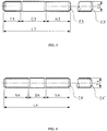
- Figure 2 shows an example of a general purpose continuous thread sud in accordance with the present invention.
- Points of continuous thread studs in accordance with the present invention are generally flat and chamfered.
- Continuous thread studs in accordance with the present invention can notably be used for piping applications ; then, as required for these applications, these ones have a length measurement requirement different from all other studs, i.e., their length is measured from first thread to first thread, exclusive points.
- Certain other threaded studs in accordance with the present invention are tap-end studs.
- Typical tap-end studs have a short thread on one end, called the tap end which is threaded to a certain Class fit (this end is suitable for screwing into a tapped hole), while the other or nut end is threaded with another Class fit.
- the tap end has a chamfered point, but the nut end may have either a chamfered or round point.
- Figure 3 shows an example of a tap-end stud in accordance with the present invention.
- Double-end studs have typically substantially equal-length or equal-length threads on each end to accommodate a nut and are threaded to a certain Class fit. Both ends may have independently from each other chamfered points or round points. Double-end studs are useful for flange bolting or other applications where torching from both ends is necessary or desirable.
- Figure 4 shows an example of a double-end stud in accordance with the present invention.
- the fastener (F) can be a scrivet. Scrivets are typically threaded fasteners that comprise an at least partially threaded shank and a head ; the shrank can be threaded on its whole surface. Certain scrivets in accordance with the present invention consist of said threaded shank and said head. Scrivets are generally inserted through holes. Scrivets are useful for assembling two or more components by an applied force which deforms the plain scrivet end to develop a completed mechanical joint.
- the fastener (F) can be a threaded bushing.
- the bushings in accordance are internally and/or externally threaded, so that they provide fasting functionality in addition to connecting functionality. Preferably, they are internally and externally threaded.
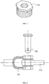
- An example of an internally and externally threaded bushing in accordance with the present invention is the hex bushing of figure 5 .
- the fastener (F) is a prevailing-torque fastener, such as a prevailing-torque screw or a prevailing-torque nut.
- a prevailing-torque fastener can be defined as a threaded fastener which is frictionally resistant to rotation due to a self-contained prevailing-torque feature ; in particular, a prevailing-torque screw can be viewed as an externally threaded fastener which is frictionally resistant to rotation due to a self-contained prevailing-torque feature, and not because of a compressive load developed against the underhead bearing surface of the screw or a tensile load developed in the shank of the screw.
- Certain prevailing-torque fasteners in accordance with the present invention are fasteners made of the polymer material (M), to which have been added an insert of a fused substance other than the polymer material (M), such a lubricant, in their threaded length.
- a fused substance other than the polymer material (M) such as a lubricant
- the dimensional characteristics of the insert may vary to achieve the performance requirements.
- Non limitative examples of arylene groups are phenylenes, naphthylenes, anthrylenes, phenanthrylenes, tetracenylenes, triphenylylenes, pyrenylenes, and perylenylenes.
- the arylene groups (especially the numbering of the ring carbon atoms) were named in accordance with the recommendations of the CRC Handbook of Chemistry and Physics, 64th edition, pages C1-C44, especially p. C11-C12 .
- a polyarylene is intended to denote a polymer of which more than 50 wt. % of the recurring units are recurring units (R) of one or more formulae consisting of an optionally substituted arylene group, provided said optionally substituted arylene group is linked by each of its two ends to two other optionally substituted arylene groups via a direct C-C linkage.
- the arylene groups of which the recurring units (R) consist can be unsubstituted. Alternatively, they can be substituted by at least one monovalent substituting group.
- the monovalent substituting group is advantageously a solubilizing group.
- a solubilizing group is one increasing the solubility of the polyarylene in at least one organic solvent, in particular in at least one of dimethylformamide, N-methylpyrrolidinone, hexamethylphosphoric triamide, benzene, tetrahydrofuran and dimethoxyethane, which can be used as solvents during the synthesis of the polyarylene by a solution polymerization process.
- the polyarylene was a kinked rigid-rod polyphenylene, the recurring units of which consisted of a mix of p-phenylene substituted by a phenylketone group with unsubstituted m-phenylene in a mole ratio p-phenylene:m-phenylene of from 10:90 to 70:30, preferably of from 25:75 to 65:35, more preferably of from 35:65 to 60:40, still more preferably of from 45:55 to 55:45, and most preferably of about 50:50.
- a kinked rigid-rod polyphenylene is commercially available from Solvay Advanced Polymers, L.L.C. as PrimoSpire ® PR-250 polyphenylene.
- the number average molecular weight of a polyarylene in general, and in particular that of the kinked rigid-rod polyarylene (P), is advantageously determined by : (1) measuring a "relative" number average molecular weight of the polyarylene by Gel Permeation Chromatography (GPC) using polystyrene calibration standards, then (2) dividing the so-measured "relative" number average molecular weight by a factor 2. It is proceeded accordingly because the skilled in the art who is a specialist of polyarylenes knows that their "relative" number average molecular weight, as measured by GPC, are generally off by a factor of about 2 times ; it has already been accounted for this correction factor in all the above cited lower and upper limits of molecular weight.
- GPC Gel Permeation Chromatography
- It can be amorphous (i.e. it has no melting point) or semi-crystalline (i.e. it has a melting point). It is preferably amorphous.
- the kinked rigid-rod polyarylene (P) is generally unbranched. In particular, it is generally essentially free, or even free, of recurring branching units wherein Ary is a polyvalent arylene and x represents the number of bonds beyond two, x ⁇ 1.
- one, two, three, or even more than three different kinked rigid-rod polyarylenes (P) can be used.
- the fastener (F) is particularly useful for demanding applications. For example, it is particularly well suited for aircrafts and other self-propelled vehicles applications where lightness, torque, strength, toughness and resistance to thermal degradation are key properties.
- the fastener (F) can be included notably in aircraft partitions, aircraft sidewalls, aircraft floorings, aircraft ceiling panels, aircraft passenger service units, aircraft infill panels, aircraft lighting sidewall and ceiling, aircraft video monitors, aircraft stow bins, aircraft oxygen boxes, aircraft HVAC ducting, aircraft food trays, aircraft arm rests, aircraft seat structures, aircraft sidewalls of lavatories, of galleys and catering trolleys, aircraft flight deck instrumentations, aircraft wire and cable harnessings and clampings, and aircraft power generation and distribution systems.
- Still another aspect of the present invention concerns the use of at least one kinked rigid-rod polyarylene (P) of which more than 50 wt. % of the recurring units are recurring units (R) of one or more formulae consisting of an optionally substituted arylene group, provided said optionally substituted arylene group is linked by each of its two ends to two other optionally substituted arylene groups via a direct C-C linkage, said recurring units (R) being a mix (M) consisting of:
Landscapes
- Chemical & Material Sciences (AREA)
- Engineering & Computer Science (AREA)
- General Engineering & Computer Science (AREA)
- Health & Medical Sciences (AREA)
- Chemical Kinetics & Catalysis (AREA)
- Medicinal Chemistry (AREA)
- Polymers & Plastics (AREA)
- Organic Chemistry (AREA)
- Mechanical Engineering (AREA)
- Compositions Of Macromolecular Compounds (AREA)
Description
- The present application claims the priority benefit to U.S. provisional application No.
61/164,599 filed on March 30, 2009 61/164,601 filed on March 30, 2009 - The present invention relates to fasteners made of a particular polyarylene material.
- Fasteners of multiple designs, including nuts, screws, clips, rivets and many other varieties, have been made available depending on the particularly encompassed application. A common feature thereof lies in the particularly stringent requirements associated herewith.
- Indeed, during their life, any fasteners, included unthreaded and threaded fasteners, are notably submitted to harsh mechanical conditions : they are stretched, twisted and bent. Fasteners are further generally submitted to various aggressive environmental, such as vibrations, thermal cycles and/or chemical attacks, which can alter their mechanical performances over time, and, in the worst scenarios, cause fasteners to be litterally "lost".
- A class of fasteners of particular importance is threaded fasteners that face with additional specific problems. When threaded fasteners are tightened, we pump energy into them, and, after we let go, this energy is held therein by friction constraints. Typically, these ones are concentrated to a large extent in the fastener threads, which yet often represent the most delicate portions of the fastener as the result of their fineness. Aggressive environmental factors as above recited can cause threaded fasteners to loose all their preload and literally be lost ("loosening" problem). Somewhat related to loosening is thread stripping, another failure which occurs when threaded fasteners are over-tightened ; thread stripping is characterized by a deformation (alteration) of the fastener threads, typically resulting in a decrease of performance.
- Certain fasteners, including certain unthreaded and threaded fasteners, can have complex designs, and shaping/machining them from an appropriate material can be a tough matter. In case of threaded fasteners, forming fine and regular threads has proved to be particularly uneasy.
- Material selection is crucial for fasteners. Metal has remained for several tens of years the only suitable choice, because no plastic material was able to provide the required level of mechanical properties, in particular a high elongational strength, a high flexural strength and, last but not least, a high torsional strength (or torque). Indeed, for many fasteners, including but not limited to threaded fasteners, load bearing ability is typically a function of the shear or torsional strength of the material of construction.
- Metal fasteners present however a certain number of disadvantages. Metal fasteners are heavy ; in contrast, certain applications, in particular self-propellant vehicles, and more particularly aircrafts, ask for light-weight materials. Metal fasteners are in general prone to corrosion ; in addition, when dissimilar metal are joined together, galvanic corrosion can occur. Metal fasteners are electrically conductive. Machining complex shapes from a metal, as well as forming fine and regular threads, is a tough matter.
- The development of engineering composites, such as carbon fiber-reinforced polyetheretherketone (PEEK) has well offered some viable alternatives to not very demanding fasteners applications. Adding fiber reinforcement increases well tensile and flexural properties, but has little effect on the shear properties. In addition, fiber reinforcement reduces tensile elongation, a measure of practical toughness. In addition, when fasteners are produced using the injection molding process with fiber reinforced materials, property variations due to flow direction occurs. In addition, when the fasteners are threaded, it is unlikely that the threads contain much fiber reinforcement, because they are relatively thin and perpendicular to the usual flow direction.
- An important progress was achieved when the use of rigid rod polyphenylenes was proposed for the first time for the manufacture of unthreaded fasteners. Then,
EP 2 014 251 describes a pin for securing the position of a part of a body (for example, a head) for medical procedures, which is made of an optionally substituted polyparaphenylene (unkinked rigid rod polyphenylene of the 1st generation), such as :


- TECAMAX® SRP polyphenylene, commercially available from Ensinger, is alleged to be such a material. As the result of their rigid molecular structure, the polyparaphenylenes of
EP 2 014 251 allow indeed for much higher torque than conventional composite polymer materials (e.g. carbon fiber-reinforced PEEK). No reinforcing fibers are needed ; homogeneous materials have distinct advantages with regard to the uniformity of mechanical properties. However, neither the proposed rigid-rod polyphenylenes of the 1st generation nor, as a matter of fact, the slightly kinked rigid-rod polyphenylenes of next generation (as notably proposed by SOLVAY ADVANCED POLYMERS, L.L.C. as PrimoSpire® PR-120) are fully satisfactory for making the pins of concern. Such polyphenylenes can be qualified as "not very satisfactory" for very demanding applications, as certain unthreaded fasteners are notably as the result of their design (shape, thickness, etc.), and as most of threaded fasteners are as the result of the mandatory presence of threads. For said very demanding fastener applications, there is still a need for a polymer material that would provide a higher tensile elongation (a measure of practical toughness). Another problem, which can even be more acute for certain designs than the previous one, results from the intrinsic rigid nature of the so-proposed polyarylenes of the 1st two generations : shaping them into articles having complex shapes or with a very low thickness by melt processing techniques such as injection molding or extrusion, remains difficult, as it was originally the case for metal. - There is thus an important need for fasteners exhibiting a confluence of characteristics including high torque, high practical toughness (high tensile elongation), high elongational strength, high stiffness, high chemical resistance, light weight, and which can be easily formed by melt-processing techniques, such as extrusion or injection-molding, including when the parts of concern have a complex shape and/or very thin portions (e.g. threads, or when an extruder with small orifices must be used).
- Document
WO 2009/012244 relates to fasteners, fastener components and in particular fastener assemblies which can be used notably for the manufacturing of aircraft components. Said fastener assemblies can be made from plastic materials, for example TORLON, other poly-amide imides, Nylon, Ultem, Peek, Polypropylene, Fluoropolymers, and engineered resin. No mention is made in this document of the possibility of using polyarylenes for the manufacture of fasteners disclosed therein. - Document
WO 2009/034086 discloses a prosthetic device, including notably a bone screw, made from polymer compositions necessarily combining two types of polymers, i.e. a polyarylene, for example PrimoSpire® PR-250, and a polyarylether, for example poly(aryl ether ketone) and/or poly(aryl ether sulfone) PAES. The polyarylene is present in a weight of at least 10 % wt and at most 90 % wt, based on the total weight of the polyarylene, poly(aryl ether ketone) and poly(aryl ether sulfone). The term "prosthetic device" is intended therein to denote an artificial device which is made to replace and act as a missing biological structure. - This need, and still other ones, are met by a self-propelled vehicle comprising at least one threaded fastener (F) comprising a polymer material (M) comprising at least one kinked rigid-rod polyarylene (P), the recurring units of which are recurring units (R) of one or more formulae consisting of an optionally substituted arylene group, provided said optionally substituted arylene group is linked by each of its two ends to two other optionally substituted arylene groups via a direct C-C linkage, as defined in
Claim 1. - For a detailed description of the invention, reference will now be made to the accompanying drawings in which :
-
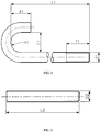
Figure 1 represents an example of a hook bolt, round bent; A, L, R, C, T and D are the characteristic dimensions of said hook bolt. -
Figure 2 represents an example of a continuous thread stud in accordance with the present invention. -
Figure 3 represents an example of a tap-end stud in accordance with the present invention. -
Figure 4 represents an example of a tap-end stud in accordance with the present invention. -
Figure 5 represents an example of an internally and externally threaded bushing in accordance with the present invention. -
Figure 6 represents an example of a clevis pin according to the present invention which joins a yoke to a rod end. -
Figure 7 represents in A : a new cotter pin, B : an installed cotter pin, C : a spring pin, D : a cross-section of a cotter pin (traditional design). -
Figure 8 represents an example of a taper pin in accordance with the present invention. -
Figure 9 represents an example of fasteners made of PrimoSpire® PR-250 polyphenylene in accordance with the present invention. - All the terms as herein used to describe the fastener (F) are well familiar to the skilled person, and should be understood under their common meaning.
- The fastener (F) is generally a mechanical device designed specifically to hold, join, couple, assemble or maintain equilibrium of single or multiple components. The resulting assembly may function dynamically or statically as a primary or secondary component of a mechanism or structure. Based on the application intended, the fastener (F) may receive varying degrees of built-in precision and engineering capability, ensuring adequate, sound service under planned, pre-established environmental conditions.
- The fastener (F) consists of the polymer material (M).
- The fastener (F) may consist of one part, i.e. it is a single-component device. Then, the single part consists of the polymer material (M). Alternatively, the fastener (F) may consist of several parts. The case being, either one part or several parts of the fastener (F) may consist of the polymer material (M). When several parts of the fastener (F) consist of the polymer material (M), each of them may consist of the very same polymer material (M) ; alternatively, at least two of them may consist of different polymer materials (M) in accordance with the invention.
- The fastener (F) is a threaded fastener, i.e. a fastener that contains threads.
- Threads are typically ridges (i.e. raised lines or strips) or grooves or ribs that are present on at least part of the surface of a threaded fastener. Threads can have different forms, including spiral, helical or parallel. Threads can notably be present around the circumference of certain screws, bolts and nuts.
- Advantageously, at least part of the threads contained in the fastener (F) is composed of the polymer material (M). Preferably, essentially all the threads contained in the fastener (F) are composed of the polymer material (M). More preferably, all the threads contained in the fastener (F) are composed of the polymer material (M).
- The threaded surface of a threaded fastener in accordance with the present invention, in particular when essentially all its threads are composed of the polymer material (M), can represent above I %, above 2 %, above 5 %, above 10 %, above 20 %, above 30 %, above 40 %, above 50 %, above 60 %, above 70 %, above 80 %, above 90 %, above 95 %, above 99 % or about 100 % of the whole surface developed by said threaded fastener.
- The fastener (F) can be externally threaded, i.e. it can have threads formed on at least part of the outside of a cylinder or other volume, such as on bolts and screws. The threaded surface of an externally threaded fastener in accordance with the present invention, in particular when essentially all its threads are composed of the polymer material (M), can represent above I %, above 2 %, above 5 %, above 10 %, above 20 %, above 30 %, above 40 %, above 50 %, above 60 %, above 70 %, above 80 %, above 90 %, above 95 %, above 99 % or about 100 % of the external surface developed by said externally threaded fastener.
- The fastener (F) can be internally threaded, i.e. it can have threads formed on at least part of the inside of a cylinder or other volume, such as on nuts. The threaded surface of an internally threaded fastener in accordance with the present invention, in particular when essentially all its threads are composed of the polymer material (M), can represent above 1 %, above 2 %, above 5 %, above 10 %, above 20 %, above 30 %, above 40 %, above 50 %, above 60 %, above 70 %, above 80 %, above 90 %, above 95 %, above 99 % or about 100 % of the interior surface developed by said internally threaded fastener.
- The fastener (F) can be both internally and externally threaded, i.e. it can have threads formed on at least part of the outside of a cylinder or other volume, and threads formed on at least part of the inside of said cylinder or other volume, such as certain internally and externally threaded bushings.
- The present invention is especially useful when the fastener (F) is a threaded fastener, with outstanding results being obtained when essentially all the threads of the threaded fastener are composed of the polymer material (M) and the threaded surface of the threaded fastener represents above 10 %, preferably above 20 %, and more preferably above 50 % of its whole surface.
- Common types of threaded fasteners in accordance with the present invention include bolts, nuts, screws, headless set screws, scrivets, threaded studs and threaded bushings.
- The fastener (F) can be a bolt. A bolt is typically a headed, externally threaded fastener. A bolt is generally designed for insertion through holes in assembled parts to mate with a nut, and is normally intended to be tightened or released by turning that nut.
- Certain bolts in accordance with the present invention are qualified as "bent bolts" in reference to their shape. Bent bolts may be notably in the shape of a "U", "J", "L", or eyebolts. "U" shaped bolts have typically threads at their both ends, while the other cited bent bolts have typically threads at only one end.
- Other bolts in accordance with the present invention are :
- square bolts, in reference to the shape of their head which is square ;
- hex bolts, in reference to the shape of their head which is hexagonal;
- hex flange bolts, which are similar to hex bolts but contain a washer-like flat surface that mates with a substrate ;
- round head bolts, which have typically a rounded headed at one end ; among them, it can be distinguished notably between round head short square neck bolts, round head ribbed neck bolts, round head fin neck bolts, step bolts, countersunk bolts and slotted countersunk bolts, flat countersunk head elevator bolts, T-head bolts, plow bolts and track bolts ;
- eyebolts, which have typically a looped head designed to receive a hook or rope, as in the exemplified hook bolt of
figure 1 . - The fastener (F) can be a nut. A nut is typically a perforated block possessing an internal, or female, screw thread, intended for use on an external, or male, thread such as a bolt for the purpose of tightening or holding two or more bodies in definite relating positions.
- Certain nuts in accordance with the present invention are flange nuts. Flange nuts have typically a wide flange at one end that acts as an integrated, non-spinning washer ; this serves usually to distribute the pressure of the nut over the part being secured, reducing the chance of damage to the part and making it less likely to loosen as a result of an uneven fastening surface. The flange is commonly serrated to provide a locking action.
- Certain other nuts in accordance with the present invention are coupling nuts. Coupling nuts are typically long nuts tapped from each side to meet in the middle, rather than all the way through in the same direction, which can be used to connect two threaded rods end to end.
- Still certain other nuts in accordance with the present invention are wing nuts, also called thumbnuts. These ones are typically nuts with wing like projections for thumb and forefinger leverage in turning.
- The fastener (F) can be a screw. A screw is typically a headed and externally threaded fastener. It has usually capabilities which permit it to be inserted into holes in assembled parts, of mating with a preformed internal thread or forming its own thread, and of being tightened or released by torquing its head.
- Certain screws in accordance with the present invention are socket screws. Socket screws are typically screw caps with a hex, spline, or special hole in the top that requires a matching "screwdriver tip".
- Certain other screws in accordance with the present invention are tapping screws. Tapping screws are able to "tap" their own mating internal thread when driven into preformed holes in various materials. Tapping screws are typically high strength, one-piece, one-side-installation threaded fasteners. Because they can form or cut their own mating thread, there is unusually good thread fit which enhances resistance to their loosening in service. Tapping screws in accordance with the present invention can be disassembled and are generally reusable.
- Still other screws in accordance with the present invention are machine screws. Machine screws have typically a thread along the entire length of their shaft; they can also be viewed as screws with a tapered top that fits into a countersunk hole and when screwed in is flush with the surface being screwed into.
- Still other screws in accordance with the present invention are thumb or wing screws, i.e. screws which are typically designed so that they can be turned with the thumb and fingers.
- Still other screws in accordance with the present invention are qualified as "wood screws", in that they have typically a pointed shank, a slotted or recessed head, and a sharp tapered thread of relatively coarse pitch suitable for use essentially, if not only, in wood.
- Still other screws in accordance with the present invention are qualified as miniature screws by reference to their tiny size. Among said miniature screws, it can be notably cited fillister heads, pan head, flat heads and binding heads.
- Screw-washer assemblies (SEMS) wherein at least the screw comprises the polymer material (M) form also part of the present invention.
- The fastener (F) can be a headless set screw. In contrast with the screw in accordance with the present invention as above defined which is typically headed, the present headless set screw has no projecting head. In general, its top is either slotted or provided with a socket.
- The fastener (F) can be a threaded stud. A threaded stud is typically a fastening device with one pointed end driven into a material, such as concrete, and the other end is threaded and extends above the surface for the attachment of structural members.
- Certain threaded studs in accordance with the present invention are continuous thread studs, i.e. they are threaded from end to end, and are often used for flange bolting with two nuts applied.
Figure 2 shows an example of a general purpose continuous thread sud in accordance with the present invention. - Points of continuous thread studs in accordance with the present invention are generally flat and chamfered. Continuous thread studs in accordance with the present invention can notably be used for piping applications ; then, as required for these applications, these ones have a length measurement requirement different from all other studs, i.e., their length is measured from first thread to first thread, exclusive points.
- Certain other threaded studs in accordance with the present invention are tap-end studs. Typical tap-end studs have a short thread on one end, called the tap end which is threaded to a certain Class fit (this end is suitable for screwing into a tapped hole), while the other or nut end is threaded with another Class fit. The tap end has a chamfered point, but the nut end may have either a chamfered or round point.
Figure 3 shows an example of a tap-end stud in accordance with the present invention. - Still other threaded studs in accordance with the present invention are double-end studs. Double-end studs have typically substantially equal-length or equal-length threads on each end to accommodate a nut and are threaded to a certain Class fit. Both ends may have independently from each other chamfered points or round points. Double-end studs are useful for flange bolting or other applications where torching from both ends is necessary or desirable.
Figure 4 shows an example of a double-end stud in accordance with the present invention. - The fastener (F) can be a scrivet. Scrivets are typically threaded fasteners that comprise an at least partially threaded shank and a head ; the shrank can be threaded on its whole surface. Certain scrivets in accordance with the present invention consist of said threaded shank and said head. Scrivets are generally inserted through holes. Scrivets are useful for assembling two or more components by an applied force which deforms the plain scrivet end to develop a completed mechanical joint.
- The fastener (F) can be a threaded bushing. The bushings in accordance are internally and/or externally threaded, so that they provide fasting functionality in addition to connecting functionality. Preferably, they are internally and externally threaded. An example of an internally and externally threaded bushing in accordance with the present invention is the hex bushing of
figure 5 . - In a special embodiment of the present invention, the fastener (F) is a prevailing-torque fastener, such as a prevailing-torque screw or a prevailing-torque nut. A prevailing-torque fastener can be defined as a threaded fastener which is frictionally resistant to rotation due to a self-contained prevailing-torque feature ; in particular, a prevailing-torque screw can be viewed as an externally threaded fastener which is frictionally resistant to rotation due to a self-contained prevailing-torque feature, and not because of a compressive load developed against the underhead bearing surface of the screw or a tensile load developed in the shank of the screw. Certain prevailing-torque fasteners in accordance with the present invention are fasteners made of the polymer material (M), to which have been added an insert of a fused substance other than the polymer material (M), such a lubricant, in their threaded length. Depending on the amount of friction present because of the surface finish and lubricants, the dimensional characteristics of the insert may vary to achieve the performance requirements.
- For the purpose of the present invention, an arylene group is a hydrocarbon divalent group consisting of one core composed of one benzenic ring or of a plurality of benzenic rings fused together by sharing two or more neighboring ring carbon atoms, and of two ends.
- Non limitative examples of arylene groups are phenylenes, naphthylenes, anthrylenes, phenanthrylenes, tetracenylenes, triphenylylenes, pyrenylenes, and perylenylenes. The arylene groups (especially the numbering of the ring carbon atoms) were named in accordance with the recommendations of the CRC Handbook of Chemistry and Physics, 64th edition, pages C1-C44, especially p. C11-C12.
- Arylene groups present usually a certain level of aromaticity ; for this reason, they are often reported as "aromatic" groups. The level of aromaticity of the arylene groups depends on the nature of the arylene group ; as thoroughly explained in Chem. Rev. 2003, 103, 3449-3605, "Aromaticity of Polycyclic Conjugated Hydrocarbons", the level of aromaticity of a polycyclic aromatic hydrocarbon can be notably quantified by the "index of benzene character" B, as defined on p. 3531 of the same paper ; values of B for a large set of polycyclic aromatic hydrocarbon are reported on table 40, same page.
- An end of an arylene group is a free electron of a carbon atom contained in a (or the) benzenic ring of the arylene group, wherein an hydrogen atom linked to said carbon atom has been removed. Each end of an arylene group is capable of forming a linkage with another chemical group. An end of an arylene group, or more precisely the linkage capable of being formed by said end, can be characterized by a direction and by a sense ; to the purpose of the present invention, the sense of the end of an arylene group is defined as going from the inside of the core of the arylene group to the outside of said core. As concerns more precisely arylene groups the ends of which have the same direction, such ends can be either of the same or opposite sense ; also, their ends can be in the straight foregoing of each other, or not (otherwise said, they can be disjoint).
- A polyarylene is intended to denote a polymer of which more than 50 wt. % of the recurring units are recurring units (R) of one or more formulae consisting of an optionally substituted arylene group, provided said optionally substituted arylene group is linked by each of its two ends to two other optionally substituted arylene groups via a direct C-C linkage. That the optionally substituted arylene group is linked by each of its two ends to two other optionally substituted arylene groups via a direct C-C linkage, is an essential feature of the recurring units (R) ; thus, an arylene recurring unit which is linked by at least one of its two ends to a group other than an arylene group such as phenylene recurring units ϕ1, ϕ2 and ϕ2' below :
- O - ϕ1 - S(=O)2 -,
- O - ϕ2 - ϕ2' - O -
- The arylene groups of which the recurring units (R) consist can be unsubstituted. Alternatively, they can be substituted by at least one monovalent substituting group.
- The monovalent substituting group is usually not polymeric in nature ; its molecular weight is preferably below 500, more preferably below 300, still more preferably below 200 and most preferably below 150.
- The monovalent substituting group is advantageously a solubilizing group. A solubilizing group is one increasing the solubility of the polyarylene in at least one organic solvent, in particular in at least one of dimethylformamide, N-methylpyrrolidinone, hexamethylphosphoric triamide, benzene, tetrahydrofuran and dimethoxyethane, which can be used as solvents during the synthesis of the polyarylene by a solution polymerization process.
- The monovalent substituting group is also advantageously a group which increases the fusibility of the polyarylene, i.e. it lowers its glass transition temperature and its melt viscosity, so as to desirably make the polyarylene suitable for thermoprocessing.
- The monovalent substituting group is phenylketone [-C(=O)-phenyl].
- Excellent results were obtained when the polyarylene was a kinked rigid-rod polyphenylene, the recurring units of which consisted of a mix of p-phenylene substituted by a phenylketone group with unsubstituted m-phenylene in a mole ratio p-phenylene:m-phenylene of from 10:90 to 70:30, preferably of from 25:75 to 65:35, more preferably of from 35:65 to 60:40, still more preferably of from 45:55 to 55:45, and most preferably of about 50:50. Such a kinked rigid-rod polyphenylene is commercially available from Solvay Advanced Polymers, L.L.C. as PrimoSpire® PR-250 polyphenylene.
- The kinked rigid-rod polyarylene (P) has usually a number average molecular weight greater than 1000, preferably greater than 5000, more preferably greater than about 10000 and still more preferably greater than 15000. On the other hand, the number average molecular weight of the kinked rigid-rod polyarylene is usually below 100000, and preferably below 70000. In a certain embodiment, the number average molecular weight of the kinked rigid-rod polyarylene is above 35000. In another embodiment, it is of at most 35000 ; in this embodiment, it is often of at most 25000 and sometimes of at most 20000. The number average molecular weight of a polyarylene in general, and in particular that of the kinked rigid-rod polyarylene (P), is advantageously determined by : (1) measuring a "relative" number average molecular weight of the polyarylene by Gel Permeation Chromatography (GPC) using polystyrene calibration standards, then (2) dividing the so-measured "relative" number average molecular weight by a factor 2. It is proceeded accordingly because the skilled in the art who is a specialist of polyarylenes knows that their "relative" number average molecular weight, as measured by GPC, are generally off by a factor of about 2 times ; it has already been accounted for this correction factor in all the above cited lower and upper limits of molecular weight.
- It can be amorphous (i.e. it has no melting point) or semi-crystalline (i.e. it has a melting point). It is preferably amorphous.
- It has a glass transition temperature of advantageously above 50°C, preferably above 120°C and more preferably above 150°C.
- The kinked rigid-rod polyarylene (P) is generally unbranched. In particular, it is generally essentially free, or even free, of recurring branching units

- The kinked rigid-rod polyarylene (P) can be prepared by any method. A method well known in the art to prepare such kinked rigid-rod polyarylene comprises polymerizing, preferably by reductive coupling, (i) at least one dihaloarylene molecular compound consisting of an optionally substituted rigid rod-forming arylene group, which is linked on each of its two ends to one halogen atom, such as chlorine, bromine and iodine, with (ii) at least one dihaloarylene molecular compounds consisting of an optionally substituted kink-forming arylene group, which is linked on each of its two ends to one halogen atom, such as chlorine, bromine, iodine, and fluorine. The elimination of the halogen atoms from the dihaloarylene molecular compounds results in the formation of respectively optionally substituted rigid rod-forming and optionally substituted kink-forming arylene groups.
- Thus, for example :
- the elimination of both chlorine atoms from a molecule of p-dichlorobenzene, p-dichlorobiphenyl or their homologous of general formula Cl-(ϕ)N-Cl, N being an integer from 3 to 10, results in the formation of respectively 1, 2 or N adjacent p-phenylene units (rigid rod-forming arylene units) ; thus, p-dichlorobenzene, p-dichlorobiphenyl and their homologous of general formula Cl-(ϕ)N-Cl, N as above defined, can be polymerized, so as to form p-phenylene units ;
- 2,5-dichlorobenzophenone (p-dichlorobenzophenone) can be polymerized, so as to form 1,4-(benzoylphenylene) units (also rigid rod-forming arylene units) ;
- m-dichlorobenzene can be polymerized, so as to form m-phenylene units (kink-forming arylene units).
- In the present invention, one, two, three, or even more than three different kinked rigid-rod polyarylenes (P) can be used.
- The fastener (F) can find utility as such or as a component of a multitude of devices, such as ball lock pins, latches, clips, clip nuts, plug and sleeve, floating nut fasteners, isolator mounts, nut plates, split joint fittings, floor fittings, quarter turn fasteners, inserts, support brackets, mounting brackets, latches, release pins, hinges, bolt bushings, cable ties, tubing hangers, wiring clamps, standoffs, spacers, conduit brackets, etc.
- The fastener (F) is particularly useful for demanding applications. For example, it is particularly well suited for aircrafts and other self-propelled vehicles applications where lightness, torque, strength, toughness and resistance to thermal degradation are key properties.
- Thus, another aspect of the present invention concerns an aircraft comprising at least one fastener (F) as above described.
- The fastener (F) can be included notably in aircraft partitions, aircraft sidewalls, aircraft floorings, aircraft ceiling panels, aircraft passenger service units, aircraft infill panels, aircraft lighting sidewall and ceiling, aircraft video monitors, aircraft stow bins, aircraft oxygen boxes, aircraft HVAC ducting, aircraft food trays, aircraft arm rests, aircraft seat structures, aircraft sidewalls of lavatories, of galleys and catering trolleys, aircraft flight deck instrumentations, aircraft wire and cable harnessings and clampings, and aircraft power generation and distribution systems.
- Related aspects of the present invention include :
- the use of an aircraft comprising at least one fastener (F) as above described for taking passengers and/or loading goods on board ;
- the use of an aircraft comprising at least one fastener (F) as above described for transporting passengers and/or goods ;
- the use of an aircraft comprising at least one fastener (F) as above described for disembarking passengers and/or unloading goods from said aircraft;
- a flying vehicle other than an aircraft, said flying vehicle comprising at least one fastener (F) as above described, in particular helicopters, hot-air balloons, gliders, and spatial rockets and shuttles ;
- a self-propelled vehicle other than a flying vehicle, said self-propelled vehicle comprising at least one fastener (F) as above described, in particular a car, a motorbike, a trucks or a van ;
- a self-propelled vehicle comprising at least one fastener (F) as above described;
- the use of a self-propelled vehicle comprising at least one fastener (F) for transporting passengers and/or goods.
- Selected physical and mechanical properties of PrimoSpire® PR-250 polyphenylene (a highly kinked rigid-rod polyarylene of the last generation, commercially available from SOLVAY ADVANCED POLYMERS, L.L.C.), and both unreinforced and carbon fiber reinforced PEEK are shown in Table 1. Predicting fastener performance from data sheet properties is essentially impossible, as it will appear from the results below.
Table 1 Selected Mechanical and Physical Properties of Candidate Fastener Materials Property Units PrimoSpire® PR-250 PEEK PEEK - 30%CF Tensile Strength psi 22.000 14.000 30,800 MPa 152 96 212 Tensile Modulus kpsi 800 520 2,900 GPa 5.5 3.6 20.0 Elongallon at Break % ∼10 ∼20 2 Flexural Strength psi 34,000 21,700 46,200 MPa 234 150 318 Flexural Modulus Kpsi 870 545 2,560 GPa 6.0 3.8 17.6 Specific Gravity 1.19 1.30 1.41 - To demonstrate the utility of PrimoSpire® PR-250 polyphenylene as a material suitable for fasteners, in particular aerospace fasteners, a number of tests were run. Fastener tests included torque to failure and tensile strength. Both internal and external threads were evaluated.
- To evaluate internal threads, holes were drilled in plaques of the test material. The holes were then threaded using the appropriate tap. Steel machines screws were installed and the torque to failure was measured. In this test, failure occurred when the threads were stripped. The test results, shown in Table 2, indicate a clear superiority for PrimoSpire® PR-250 over 30 % carbon-fiber reinforced PEEK. Also, the data for unreinforced PEEK shows that adding 30 % carbon fiber did not improve the torque strength substantially.
Table 2 Torque to Failure Steel Bolts in Tapped Holes in Test Material Fastener Size Plaque Thickness PrimoSpire PR-250 PEEK PEEK 30% CF M2.5 0.125" (3.2 mm) 8.4 in-lb (0.94 N-m) M3 0.125" (3.2 mm) 12.6 in-lb (1.4 N-m) 9.0 in-lb (1.0 N-m) 8-32 0.25" (6.3 mm) 72 in-lb (8.1 N-m) 10-32 0.25" (6.3 mm) 81 in-lb (9.2 N-m) ¼"-20 0,25" (6.3 mm) 179 in-lb (20.2 N-m) 55 in-lb (6.2 N-m) 77 in-lb (8.7 N-m) - Hence, still another aspect of the present invention concerns the use of at least one kinked rigid-rod polyarylene (P) of which more than 50 wt. % of the recurring units are recurring units (R) of one or more formulae consisting of an optionally substituted arylene group, provided said optionally substituted arylene group is linked by each of its two ends to two other optionally substituted arylene groups via a direct C-C linkage, said recurring units (R) being a mix (M) consisting of:
- between 0 and 75 mole %, based on the total number of moles of the recurring units (R), of rigid rod-forming arylene units (Ra), said rigid rod-forming arylene units (Ra) being optionally substituted by at least one monovalent substituting group,
- between 25 and 100 mole %, based on the total number of moles of the recurring units (R), of kink-forming arylene units (Rb), said kink-forming arylene units (Rb) being optionally substituted by at least one monovalent substituting group
- To test external threads, machine screws were injection molded from the candidate resins. Holes were drilled in a steel plate that was 0.625" (16 mm) thick. The holes were threaded using the appropriate taps. The screws to be tested were installed and then torque was applied until the screws broke. The torque values are shown in Table 3. The torque required to break the PrimoSpire® PR-250 screws is about twice the torque needed to break the 30 % CF PEEK screws.
Table 3 Torque to Failure of Injection Molded Screws Fastener Size PrimoSpire® PR-250 PEEK 30% CF 8-32 11.3 in-lb (1.3 N-m) 7.0 in-lb (0.8 N-m) 10-32 26.7 in-lb (3.0 N-m) 12.6 in-lb (1.4 N.m) - Tensile strength data was obtained using the NASM 1312-8A test method and injection molded 10-32 machine screws. The results are shown in Table 4. The SRP showed higher tensile strength and a much lower standard deviation than the 30 % carbon fiber reinforced PEEK.
Table 4 Tensile Strength of 10-32 Molded Screws by NASM 1312-8A PrimoSpire® PR-250 PEEK 30% CF Load at Fracture 451 lb (204 kg) 391 lb (177 kg) Standard Deviation 5.3 lb (2.4kg) 16.5 lb (7.5 kg) - The present experimental data were generated on machine screws, but the conclusions apply to many fastener types, such as bolts, nuts, washers, pins, and scrivets. Engineered fasteners like clip nuts, nut plates, mounts, inserts, latches, hinges, clamps, and spacers should also be considered as candidates for weight reduction and performance enhancement. As important as the weight reduction and high strength that a highly kinked rigid-rod polyarylene such as PrimoSpire® PR-250 can supply in an aircraft fastener, there is also the benefit created through the use of an inherently, electrically, non-conductive material. The electrical properties of the PrimoSpire® PR-250 and the 30 % carbon fiber PEEK are shown in Table 5.
Table 5 Selected Electrical Properties Property PR-250 PEEK 30%CF Units Volume Resistivity, ASTM D257 >7x10¹⁵ 5x10⁷ ohm-cm Surface Resistivity, ASTM D257 >5x10¹⁵ ohm/sq Dielectric Strength, ASTM D149 505 (20) V/mil (kV/mm) - Eliminating the juncture of dissimilar metals prevents galvanic corrosion. Since corrosion can occur even with similar metals, the use of a non-conductive fastener provides additional protection from corrosion. This often results in lower maintenance costs and reduced downtime. The thermoplastic molded fastener will never corrode or participate in any galvanic corrosion of other components. Flammability, smoke generation, and toxicity data for the PrimoSpire® PR-250 material is shown in Table 6. As the data suggest, the material is inherently flame retardant (without additives), generates little smoke, and is non-toxic, all desirable characteristics for aircraft applications.
Table 6 Flame, Smoke, and Toxicity Values of PrimoSpire® PR-250 Property Test Method Value OSU 2 min. Peak FAR 25.853 10 kW/min-m2 OSU 5 min. Total FAR 25.853 30 kW/min-m2 Vertical Burn DMS 1510 2" (51 mm) Dm @ 4 min. F814/ E662 1 Toxicity, ppm BSS 7239/ HCN<1 ATS 1000/ CO<1 ABD0031 N0+N02<1 S02 <1 HF 10 HCl 5 - A photograph showing different fasteners made of PrimoSpire® PR-250 polyphenylene, a highly kinked rigid-rod polyarylene of the last generation, are shown in
Figure 9 for illustrative purposes.
Claims (7)
- A self-propelled vehicle comprising at least one threaded fastener (F) consisting of a polymer material (M) consisting of at least one kinked rigid-rod polyarylene (P)(i) the recurring units of which are recurring units (R) of one or more formulae consisting of an optionally substituted arylene group, provided said optionally substituted arylene group is linked by each of its two ends to two other optionally substituted arylene groups via a direct C-C linkage, and(ii) the recurring units of which consist of a mix of p-phenylene units substituted by a phenylketone group with unsubstituted m-phenylene units, in a mole ratio p-phenylene:m-phenylene of from10:90 to 70:30.
- The self-propelled vehicle according to claim 1, wherein the mole ratio p-phenylene:m-phenylene of the kinked rigid-rod polyarylene (P) is of from 25:75 to 65:35.
- The self-propelled vehicle according to any one of the preceding claims, wherein the mole ratio p-phenylene:m-phenylene of the kinked rigid-rod polyarylene (P) is of from 45:55 to 55:45.
- The self-propelled vehicle according to any of the preceding claims, characterized in that all the threads of the threaded fastener are composed of the polymer material (M) and the threaded surface represents above 20 % of its whole surface.
- The self-propelled vehicle according to anyone of the preceding claims, characterized in that the threaded fastener is selected from the group consisting of bolts, nuts, screws, headless set screws, scrivets, threaded studs and threaded bushings.
- Self-propelled vehicle according to anyone of the preceding claims, characterized in that it is an aircraft.
- Self-propelled vehicle according to Claim 6, wherein the fastener (F) is included in at least one of aircraft partitions, aircraft sidewalls, aircraft floorings, aircraft ceiling panels, aircraft passenger service units, aircraft infill panels, aircraft lighting sidewall and ceiling, aircraft video monitors, aircraft stow bins, aircraft oxygen boxes, aircraft HVAC ducting, aircraft food trays, aircraft arm rests, aircraft seat structures, aircraft sidewalls of lavatories, of galleys and catering trolleys, aircraft flight deck instrumentations, aircraft wire and cable harnessings and clampings, and aircraft power generation and distribution systems.
Applications Claiming Priority (3)
| Application Number | Priority Date | Filing Date | Title |
|---|---|---|---|
| US16459909P | 2009-03-30 | 2009-03-30 | |
| US16460109P | 2009-03-30 | 2009-03-30 | |
| PCT/EP2010/054048 WO2010112435A1 (en) | 2009-03-30 | 2010-03-26 | Fasteners made of a polymer material |
Publications (2)
| Publication Number | Publication Date |
|---|---|
| EP2413984A1 EP2413984A1 (en) | 2012-02-08 |
| EP2413984B1 true EP2413984B1 (en) | 2017-08-23 |
Family
ID=42166784
Family Applications (1)
| Application Number | Title | Priority Date | Filing Date |
|---|---|---|---|
| EP10710589.2A Active EP2413984B1 (en) | 2009-03-30 | 2010-03-26 | Fasteners made of a polymer material |
Country Status (4)
| Country | Link |
|---|---|
| US (1) | US9006384B2 (en) |
| EP (1) | EP2413984B1 (en) |
| JP (1) | JP5805065B2 (en) |
| WO (2) | WO2010112435A1 (en) |
Families Citing this family (27)
| Publication number | Priority date | Publication date | Assignee | Title |
|---|---|---|---|---|
| EP1998056A1 (en) * | 2007-05-29 | 2008-12-03 | Sgl Carbon Ag | Composite fastener for ceramic components |
| JP5805065B2 (en) | 2009-03-30 | 2015-11-04 | ソルベイ・アドバンスト・ポリマーズ・エルエルシー | Fasteners made of polymer material |
| KR101091426B1 (en) * | 2009-11-06 | 2011-12-07 | 주식회사 니프코코리아 | Battery case |
| US9267748B2 (en) * | 2011-09-29 | 2016-02-23 | Alan T. Thordsen | Systems and methods for releasing detachable firearm magazines |
| EP2765317A1 (en) * | 2013-02-12 | 2014-08-13 | Solvay Specialty Polymers USA, LLC. | Improved fasteners |
| EP2851387A1 (en) | 2013-09-19 | 2015-03-25 | Solvay Specialty Polymers USA, LLC. | Oil and gas recovery articles |
| EP2899230A1 (en) | 2014-01-22 | 2015-07-29 | Solvay Specialty Polymers USA, LLC. | Automotive articles |
| EP2899231A1 (en) | 2014-01-22 | 2015-07-29 | Solvay Specialty Polymers USA, LLC. | Aerospace articles |
| EP2899233A1 (en) | 2014-01-22 | 2015-07-29 | Solvay Specialty Polymers USA, LLC. | Chemical processing articles |
| EP2899232A1 (en) | 2014-01-22 | 2015-07-29 | Solvay Specialty Polymers USA, LLC. | Oil and gas recovery articles |
| EP3124210B1 (en) * | 2014-03-25 | 2020-07-22 | Teijin Limited | Fiber-reinforced resin assembly having crimping part, and method for manufacturing same |
| CA2944964C (en) * | 2014-04-14 | 2022-08-09 | Short Brothers Plc | Apparatus and method for forming fiber reinforced composite structures |
| KR101617520B1 (en) * | 2014-05-30 | 2016-05-02 | 신인학 | The method of manufacturing a car seat cushion, and thus the tension Product |
| US20160101600A1 (en) | 2014-10-09 | 2016-04-14 | Baker Hughes Incorporated | Methods of forming structures for downhole applications, and related downhole structures and assemblies |
| US10337270B2 (en) * | 2015-12-16 | 2019-07-02 | Neo Products, LLC | Select fire system and method of using same |
| WO2018086873A1 (en) | 2016-11-11 | 2018-05-17 | Solvay Specialty Polymers Usa, Llc | Polyarylether ketone copolymer |
| EP3538589B1 (en) | 2016-11-11 | 2021-10-20 | Solvay Specialty Polymers USA, LLC | Polyarylether ketone copolymer |
| US10974938B2 (en) * | 2017-03-21 | 2021-04-13 | Oshkosh Defense, Llc | Vehicle lift assembly |
| KR101954078B1 (en) * | 2018-05-30 | 2019-03-06 | (주)피코팩 | A manufacturing method of oral sensor using print circuit board of build-up multi layer |
| US11300281B2 (en) * | 2018-03-16 | 2022-04-12 | Luminiz Inc. | Light fixture |
| JP2020067170A (en) * | 2018-10-26 | 2020-04-30 | トヨタ自動車株式会社 | Cap fastening structure |
| JP7665611B2 (en) | 2019-11-08 | 2025-04-21 | ソルベイ スペシャルティ ポリマーズ ユーエスエー, エルエルシー | Polyaryletherketone copolymer blends |
| WO2021089747A1 (en) | 2019-11-08 | 2021-05-14 | Solvay Specialty Polymers Usa, Llc | Blend of polyarylether ketone copolymer |
| US20210221536A1 (en) * | 2019-11-21 | 2021-07-22 | Volansi, Inc. | Drone assembly hanger |
| GB202016847D0 (en) * | 2020-10-23 | 2020-12-09 | Univ Liverpool | Method, product and apparatus |
| CN112623263A (en) * | 2020-12-23 | 2021-04-09 | 大连长丰实业总公司 | Special supporting device for aircraft canopy connecting lock |
| US20240229990A9 (en) * | 2022-10-25 | 2024-07-11 | Petróleo Brasileiro S.A. - Petrobras | Nut guide |
Citations (2)
| Publication number | Priority date | Publication date | Assignee | Title |
|---|---|---|---|---|
| WO2009034087A2 (en) * | 2007-09-11 | 2009-03-19 | Solvay Advanced Polymers, L.L.C. | New prosthetic devices |
| US20090082539A1 (en) * | 2007-09-11 | 2009-03-26 | Solvay Advanced Polymers, L.L.C. | Medical devices made of a polymer material |
Family Cites Families (20)
| Publication number | Priority date | Publication date | Assignee | Title |
|---|---|---|---|---|
| BE795354A (en) * | 1972-02-14 | 1973-05-29 | Long Lok Fasteners Corp | METHOD OF MANUFACTURING A FIXING ELEMENT FORMING A SELF-LOCKING SCREW WITH INSERTION PIECE AND ARTICLE THUS OBTAINED |
| US5654392A (en) | 1988-02-17 | 1997-08-05 | Maxdem Incorporated | Rigid-rod polymers |
| US5565543A (en) | 1988-02-17 | 1996-10-15 | Maxdem Incorporated | Rigid-rod polymers |
| US5227457A (en) | 1988-02-17 | 1993-07-13 | Maxdem Incorporated | Rigid-rod polymers |
| US5646231A (en) | 1988-02-17 | 1997-07-08 | Maxdem, Incorporated | Rigid-rod polymers |
| US5869592A (en) | 1991-08-19 | 1999-02-09 | Maxdem Incorporated | Macromonomers having reactive side groups |
| EP0599886B1 (en) | 1991-08-19 | 2001-03-21 | Mississippi Polymer Technologies, Inc. | Macromonomers having reactive end groups |
| US5302067A (en) | 1992-08-11 | 1994-04-12 | Jack Rath | Prevailing torque fastener |
| US5668245A (en) | 1995-11-02 | 1997-09-16 | Maxdem Incorporated | Polymers with heterocyclic side groups |
| US5886130A (en) | 1995-11-02 | 1999-03-23 | Maxdem Incorporated | Polyphenylene co-polymers |
| JPH10281132A (en) * | 1997-03-31 | 1998-10-20 | Ntn Corp | Resin nut, manufacture thereof, and slide screw device |
| JP2000141416A (en) * | 1998-11-12 | 2000-05-23 | Nippon Petrochem Co Ltd | Resin washer and seal member, and method for producing them |
| US20020106259A1 (en) | 2001-02-05 | 2002-08-08 | Kaufman Stephen R. | Reinforced plastic bolt with injection molded head and mold therefor |
| JP2006342862A (en) * | 2005-06-08 | 2006-12-21 | Daiwa Kasei Ind Co Ltd | Screw member |
| ATE517946T1 (en) * | 2006-03-07 | 2011-08-15 | Solvay Advanced Polymers Llc | NEW POLYARYLENE COMPOSITION |
| US7575404B2 (en) | 2006-11-01 | 2009-08-18 | Sps Technologies, Llc | Nut plate fastener assembly for composite materials |
| EP2014251B1 (en) | 2007-07-10 | 2012-05-30 | BrainLAB AG | Attachment device for securing a body made of polyphenyls in position for medical purposes and attachment device for securing a silicon nitride ceramic body in position for medical purposes |
| US20090016843A1 (en) * | 2007-07-13 | 2009-01-15 | Igor Komsitsky | Spacer Assemblies, Apparatus and Methods of Supporting Hardware |
| US7874779B2 (en) | 2007-07-23 | 2011-01-25 | The Monadnock Company | Fasteners, fastener components and fastener receptacles |
| JP5805065B2 (en) | 2009-03-30 | 2015-11-04 | ソルベイ・アドバンスト・ポリマーズ・エルエルシー | Fasteners made of polymer material |
-
2010
- 2010-03-26 JP JP2012502607A patent/JP5805065B2/en active Active
- 2010-03-26 WO PCT/EP2010/054048 patent/WO2010112435A1/en not_active Ceased
- 2010-03-26 EP EP10710589.2A patent/EP2413984B1/en active Active
- 2010-03-26 US US13/260,812 patent/US9006384B2/en active Active
- 2010-03-26 WO PCT/EP2010/054049 patent/WO2010112436A1/en not_active Ceased
Patent Citations (2)
| Publication number | Priority date | Publication date | Assignee | Title |
|---|---|---|---|---|
| WO2009034087A2 (en) * | 2007-09-11 | 2009-03-19 | Solvay Advanced Polymers, L.L.C. | New prosthetic devices |
| US20090082539A1 (en) * | 2007-09-11 | 2009-03-26 | Solvay Advanced Polymers, L.L.C. | Medical devices made of a polymer material |
Also Published As
| Publication number | Publication date |
|---|---|
| US9006384B2 (en) | 2015-04-14 |
| WO2010112436A1 (en) | 2010-10-07 |
| JP2012522195A (en) | 2012-09-20 |
| EP2413984A1 (en) | 2012-02-08 |
| US20120025020A1 (en) | 2012-02-02 |
| WO2010112435A1 (en) | 2010-10-07 |
| JP5805065B2 (en) | 2015-11-04 |
Similar Documents
| Publication | Publication Date | Title |
|---|---|---|
| US9006384B2 (en) | Fasteners made of a polymer material | |
| CN104995415B (en) | Improved fastener | |
| US10435539B2 (en) | Multi additive multifunctional composite for use in a non-metallic fuel conveyance system | |
| US20090281227A1 (en) | Polymer Composition Suitable for Electrostatic Discharge Applications | |
| EP2070996A1 (en) | Llubricating lacquer for a bearing element | |
| EP1735376B1 (en) | Method of producing a conductive resin composition | |
| MX2007009360A (en) | Thermoplastic long fiber composites, methods of manufacture thereof and articles derived therefrom. | |
| Suresha et al. | Influence of SiC filler on mechanical and tribological behavior of glass fabric reinforced epoxy composite systems | |
| Ren et al. | Hybrid effect on mechanical properties of M40‐T300 carbon fiber reinforced Bisphenol A Dicyanate ester composites | |
| Samal | Role of temperature and carbon nanotube reinforcement on epoxy based nanocomposites | |
| JPH10281132A (en) | Resin nut, manufacture thereof, and slide screw device | |
| CN103450673A (en) | Pumping rod centralizer reinforcement material with high wear resistance and preparation method thereof | |
| US20150048172A1 (en) | Insulating anti-corrosive rail clamp integrally made of polymeric composition | |
| Eremin et al. | Evaluation of tensile fatigue behavior of carbon fiber reinforced polymer modified by single‐wall carbon nanotubes | |
| Chiang | A statistical theory of the tensile strength of short-fiber-reinforced composites | |
| Li et al. | Effectual dispersion of carbon nanofibers in polyetherimide composites and their mechanical and tribological properties | |
| Suresha et al. | Influence of silicon carbide filler on mechanical and dielectric properties of glass fabric reinforced epoxy composites | |
| WO2005092517A1 (en) | Method for preparing pre-coated, composite components and components prepared thereby | |
| CN104312089B (en) | Static resistant polyamide matrix material and preparation method thereof | |
| US20150260209A1 (en) | Modular rail system | |
| Jain et al. | Comparative Study on strengthening of RC beam in flexure using CFRP & GFRP: A Review | |
| US20240067856A1 (en) | Thermally conductive thermoplastic composite with reduced percolation threshold | |
| CN220146848U (en) | White epoxy glass fiber cloth laminated board | |
| DE102015012239A1 (en) | Tribologically optimized composite material based on plastics and its use as a sliding bearing material | |
| Theberge et al. | Carbon fiber reinforced thermoplastics |
Legal Events
| Date | Code | Title | Description |
|---|---|---|---|
| PUAI | Public reference made under article 153(3) epc to a published international application that has entered the european phase |
Free format text: ORIGINAL CODE: 0009012 |
|
| 17P | Request for examination filed |
Effective date: 20111031 |
|
| AK | Designated contracting states |
Kind code of ref document: A1 Designated state(s): AT BE BG CH CY CZ DE DK EE ES FI FR GB GR HR HU IE IS IT LI LT LU LV MC MK MT NL NO PL PT RO SE SI SK SM TR |
|
| DAX | Request for extension of the european patent (deleted) | ||
| 17Q | First examination report despatched |
Effective date: 20150715 |
|
| STAA | Information on the status of an ep patent application or granted ep patent |
Free format text: STATUS: EXAMINATION IS IN PROGRESS |
|
| GRAP | Despatch of communication of intention to grant a patent |
Free format text: ORIGINAL CODE: EPIDOSNIGR1 |
|
| STAA | Information on the status of an ep patent application or granted ep patent |
Free format text: STATUS: GRANT OF PATENT IS INTENDED |
|
| INTG | Intention to grant announced |
Effective date: 20170511 |
|
| GRAS | Grant fee paid |
Free format text: ORIGINAL CODE: EPIDOSNIGR3 |
|
| GRAA | (expected) grant |
Free format text: ORIGINAL CODE: 0009210 |
|
| STAA | Information on the status of an ep patent application or granted ep patent |
Free format text: STATUS: THE PATENT HAS BEEN GRANTED |
|
| AK | Designated contracting states |
Kind code of ref document: B1 Designated state(s): AT BE BG CH CY CZ DE DK EE ES FI FR GB GR HR HU IE IS IT LI LT LU LV MC MK MT NL NO PL PT RO SE SI SK SM TR |
|
| REG | Reference to a national code |
Ref country code: GB Ref legal event code: FG4D |
|
| REG | Reference to a national code |
Ref country code: CH Ref legal event code: EP |
|
| REG | Reference to a national code |
Ref country code: AT Ref legal event code: REF Ref document number: 920644 Country of ref document: AT Kind code of ref document: T Effective date: 20170915 |
|
| REG | Reference to a national code |
Ref country code: IE Ref legal event code: FG4D |
|
| REG | Reference to a national code |
Ref country code: DE Ref legal event code: R096 Ref document number: 602010044593 Country of ref document: DE |
|
| REG | Reference to a national code |
Ref country code: NL Ref legal event code: MP Effective date: 20170823 |
|
| REG | Reference to a national code |
Ref country code: LT Ref legal event code: MG4D |
|
| REG | Reference to a national code |
Ref country code: AT Ref legal event code: MK05 Ref document number: 920644 Country of ref document: AT Kind code of ref document: T Effective date: 20170823 |
|
| PG25 | Lapsed in a contracting state [announced via postgrant information from national office to epo] |
Ref country code: SE Free format text: LAPSE BECAUSE OF FAILURE TO SUBMIT A TRANSLATION OF THE DESCRIPTION OR TO PAY THE FEE WITHIN THE PRESCRIBED TIME-LIMIT Effective date: 20170823 Ref country code: LT Free format text: LAPSE BECAUSE OF FAILURE TO SUBMIT A TRANSLATION OF THE DESCRIPTION OR TO PAY THE FEE WITHIN THE PRESCRIBED TIME-LIMIT Effective date: 20170823 Ref country code: NO Free format text: LAPSE BECAUSE OF FAILURE TO SUBMIT A TRANSLATION OF THE DESCRIPTION OR TO PAY THE FEE WITHIN THE PRESCRIBED TIME-LIMIT Effective date: 20171123 Ref country code: FI Free format text: LAPSE BECAUSE OF FAILURE TO SUBMIT A TRANSLATION OF THE DESCRIPTION OR TO PAY THE FEE WITHIN THE PRESCRIBED TIME-LIMIT Effective date: 20170823 Ref country code: AT Free format text: LAPSE BECAUSE OF FAILURE TO SUBMIT A TRANSLATION OF THE DESCRIPTION OR TO PAY THE FEE WITHIN THE PRESCRIBED TIME-LIMIT Effective date: 20170823 Ref country code: NL Free format text: LAPSE BECAUSE OF FAILURE TO SUBMIT A TRANSLATION OF THE DESCRIPTION OR TO PAY THE FEE WITHIN THE PRESCRIBED TIME-LIMIT Effective date: 20170823 Ref country code: HR Free format text: LAPSE BECAUSE OF FAILURE TO SUBMIT A TRANSLATION OF THE DESCRIPTION OR TO PAY THE FEE WITHIN THE PRESCRIBED TIME-LIMIT Effective date: 20170823 |
|
| REG | Reference to a national code |
Ref country code: FR Ref legal event code: PLFP Year of fee payment: 9 |
|
| PG25 | Lapsed in a contracting state [announced via postgrant information from national office to epo] |
Ref country code: PL Free format text: LAPSE BECAUSE OF FAILURE TO SUBMIT A TRANSLATION OF THE DESCRIPTION OR TO PAY THE FEE WITHIN THE PRESCRIBED TIME-LIMIT Effective date: 20170823 Ref country code: BG Free format text: LAPSE BECAUSE OF FAILURE TO SUBMIT A TRANSLATION OF THE DESCRIPTION OR TO PAY THE FEE WITHIN THE PRESCRIBED TIME-LIMIT Effective date: 20171123 Ref country code: IS Free format text: LAPSE BECAUSE OF FAILURE TO SUBMIT A TRANSLATION OF THE DESCRIPTION OR TO PAY THE FEE WITHIN THE PRESCRIBED TIME-LIMIT Effective date: 20171223 Ref country code: LV Free format text: LAPSE BECAUSE OF FAILURE TO SUBMIT A TRANSLATION OF THE DESCRIPTION OR TO PAY THE FEE WITHIN THE PRESCRIBED TIME-LIMIT Effective date: 20170823 Ref country code: ES Free format text: LAPSE BECAUSE OF FAILURE TO SUBMIT A TRANSLATION OF THE DESCRIPTION OR TO PAY THE FEE WITHIN THE PRESCRIBED TIME-LIMIT Effective date: 20170823 Ref country code: GR Free format text: LAPSE BECAUSE OF FAILURE TO SUBMIT A TRANSLATION OF THE DESCRIPTION OR TO PAY THE FEE WITHIN THE PRESCRIBED TIME-LIMIT Effective date: 20171124 |
|
| PG25 | Lapsed in a contracting state [announced via postgrant information from national office to epo] |
Ref country code: DK Free format text: LAPSE BECAUSE OF FAILURE TO SUBMIT A TRANSLATION OF THE DESCRIPTION OR TO PAY THE FEE WITHIN THE PRESCRIBED TIME-LIMIT Effective date: 20170823 Ref country code: RO Free format text: LAPSE BECAUSE OF FAILURE TO SUBMIT A TRANSLATION OF THE DESCRIPTION OR TO PAY THE FEE WITHIN THE PRESCRIBED TIME-LIMIT Effective date: 20170823 Ref country code: CZ Free format text: LAPSE BECAUSE OF FAILURE TO SUBMIT A TRANSLATION OF THE DESCRIPTION OR TO PAY THE FEE WITHIN THE PRESCRIBED TIME-LIMIT Effective date: 20170823 |
|
| REG | Reference to a national code |
Ref country code: DE Ref legal event code: R097 Ref document number: 602010044593 Country of ref document: DE |
|
| PG25 | Lapsed in a contracting state [announced via postgrant information from national office to epo] |
Ref country code: EE Free format text: LAPSE BECAUSE OF FAILURE TO SUBMIT A TRANSLATION OF THE DESCRIPTION OR TO PAY THE FEE WITHIN THE PRESCRIBED TIME-LIMIT Effective date: 20170823 Ref country code: SK Free format text: LAPSE BECAUSE OF FAILURE TO SUBMIT A TRANSLATION OF THE DESCRIPTION OR TO PAY THE FEE WITHIN THE PRESCRIBED TIME-LIMIT Effective date: 20170823 Ref country code: IT Free format text: LAPSE BECAUSE OF FAILURE TO SUBMIT A TRANSLATION OF THE DESCRIPTION OR TO PAY THE FEE WITHIN THE PRESCRIBED TIME-LIMIT Effective date: 20170823 Ref country code: SM Free format text: LAPSE BECAUSE OF FAILURE TO SUBMIT A TRANSLATION OF THE DESCRIPTION OR TO PAY THE FEE WITHIN THE PRESCRIBED TIME-LIMIT Effective date: 20170823 |
|
| PLBE | No opposition filed within time limit |
Free format text: ORIGINAL CODE: 0009261 |
|
| STAA | Information on the status of an ep patent application or granted ep patent |
Free format text: STATUS: NO OPPOSITION FILED WITHIN TIME LIMIT |
|
| 26N | No opposition filed |
Effective date: 20180524 |
|
| PG25 | Lapsed in a contracting state [announced via postgrant information from national office to epo] |
Ref country code: SI Free format text: LAPSE BECAUSE OF FAILURE TO SUBMIT A TRANSLATION OF THE DESCRIPTION OR TO PAY THE FEE WITHIN THE PRESCRIBED TIME-LIMIT Effective date: 20170823 |
|
| REG | Reference to a national code |
Ref country code: CH Ref legal event code: PL |
|
| PG25 | Lapsed in a contracting state [announced via postgrant information from national office to epo] |
Ref country code: MC Free format text: LAPSE BECAUSE OF FAILURE TO SUBMIT A TRANSLATION OF THE DESCRIPTION OR TO PAY THE FEE WITHIN THE PRESCRIBED TIME-LIMIT Effective date: 20170823 |
|
| REG | Reference to a national code |
Ref country code: BE Ref legal event code: MM Effective date: 20180331 |
|
| REG | Reference to a national code |
Ref country code: IE Ref legal event code: MM4A |
|
| PG25 | Lapsed in a contracting state [announced via postgrant information from national office to epo] |
Ref country code: LU Free format text: LAPSE BECAUSE OF NON-PAYMENT OF DUE FEES Effective date: 20180326 |
|
| PG25 | Lapsed in a contracting state [announced via postgrant information from national office to epo] |
Ref country code: IE Free format text: LAPSE BECAUSE OF NON-PAYMENT OF DUE FEES Effective date: 20180326 |
|
| PG25 | Lapsed in a contracting state [announced via postgrant information from national office to epo] |
Ref country code: BE Free format text: LAPSE BECAUSE OF NON-PAYMENT OF DUE FEES Effective date: 20180331 Ref country code: CH Free format text: LAPSE BECAUSE OF NON-PAYMENT OF DUE FEES Effective date: 20180331 Ref country code: LI Free format text: LAPSE BECAUSE OF NON-PAYMENT OF DUE FEES Effective date: 20180331 |
|
| PG25 | Lapsed in a contracting state [announced via postgrant information from national office to epo] |
Ref country code: MT Free format text: LAPSE BECAUSE OF NON-PAYMENT OF DUE FEES Effective date: 20180326 |
|
| PG25 | Lapsed in a contracting state [announced via postgrant information from national office to epo] |
Ref country code: TR Free format text: LAPSE BECAUSE OF FAILURE TO SUBMIT A TRANSLATION OF THE DESCRIPTION OR TO PAY THE FEE WITHIN THE PRESCRIBED TIME-LIMIT Effective date: 20170823 |
|
| PG25 | Lapsed in a contracting state [announced via postgrant information from national office to epo] |
Ref country code: HU Free format text: LAPSE BECAUSE OF FAILURE TO SUBMIT A TRANSLATION OF THE DESCRIPTION OR TO PAY THE FEE WITHIN THE PRESCRIBED TIME-LIMIT; INVALID AB INITIO Effective date: 20100326 Ref country code: PT Free format text: LAPSE BECAUSE OF FAILURE TO SUBMIT A TRANSLATION OF THE DESCRIPTION OR TO PAY THE FEE WITHIN THE PRESCRIBED TIME-LIMIT Effective date: 20170823 |
|
| PG25 | Lapsed in a contracting state [announced via postgrant information from national office to epo] |
Ref country code: CY Free format text: LAPSE BECAUSE OF FAILURE TO SUBMIT A TRANSLATION OF THE DESCRIPTION OR TO PAY THE FEE WITHIN THE PRESCRIBED TIME-LIMIT Effective date: 20170823 Ref country code: MK Free format text: LAPSE BECAUSE OF NON-PAYMENT OF DUE FEES Effective date: 20170823 |
|
| P01 | Opt-out of the competence of the unified patent court (upc) registered |
Effective date: 20230624 |
|
| PGFP | Annual fee paid to national office [announced via postgrant information from national office to epo] |
Ref country code: GB Payment date: 20260209 Year of fee payment: 17 |
|
| PGFP | Annual fee paid to national office [announced via postgrant information from national office to epo] |
Ref country code: DE Payment date: 20260204 Year of fee payment: 17 |
|
| PGFP | Annual fee paid to national office [announced via postgrant information from national office to epo] |
Ref country code: FR Payment date: 20260209 Year of fee payment: 17 |