EP2413702B1 - Carcass cutting method and apparatus - Google Patents
Carcass cutting method and apparatus Download PDFInfo
- Publication number
- EP2413702B1 EP2413702B1 EP10759094.5A EP10759094A EP2413702B1 EP 2413702 B1 EP2413702 B1 EP 2413702B1 EP 10759094 A EP10759094 A EP 10759094A EP 2413702 B1 EP2413702 B1 EP 2413702B1
- Authority
- EP
- European Patent Office
- Prior art keywords
- carcass
- carcass portion
- imaging
- robotic arm
- cut
- Prior art date
- Legal status (The legal status is an assumption and is not a legal conclusion. Google has not performed a legal analysis and makes no representation as to the accuracy of the status listed.)
- Active
Links
Images






Classifications
-
- G—PHYSICS
- G01—MEASURING; TESTING
- G01N—INVESTIGATING OR ANALYSING MATERIALS BY DETERMINING THEIR CHEMICAL OR PHYSICAL PROPERTIES
- G01N33/00—Investigating or analysing materials by specific methods not covered by groups G01N1/00 - G01N31/00
- G01N33/02—Food
- G01N33/12—Meat; Fish
-
- A—HUMAN NECESSITIES
- A22—BUTCHERING; MEAT TREATMENT; PROCESSING POULTRY OR FISH
- A22B—SLAUGHTERING
- A22B5/00—Accessories for use during or after slaughtering
- A22B5/0017—Apparatus for cutting, dividing or deboning carcasses
- A22B5/0041—Electronic, robotic or computer assisted cutting, dividing or deboning carcasses
-
- A—HUMAN NECESSITIES
- A22—BUTCHERING; MEAT TREATMENT; PROCESSING POULTRY OR FISH
- A22C—PROCESSING MEAT, POULTRY, OR FISH
- A22C17/00—Other devices for processing meat or bones
- A22C17/02—Apparatus for holding meat or bones while cutting
-
- G—PHYSICS
- G01—MEASURING; TESTING
- G01N—INVESTIGATING OR ANALYSING MATERIALS BY DETERMINING THEIR CHEMICAL OR PHYSICAL PROPERTIES
- G01N23/00—Investigating or analysing materials by the use of wave or particle radiation, e.g. X-rays or neutrons, not covered by groups G01N3/00 – G01N17/00, G01N21/00 or G01N22/00
- G01N23/02—Investigating or analysing materials by the use of wave or particle radiation, e.g. X-rays or neutrons, not covered by groups G01N3/00 – G01N17/00, G01N21/00 or G01N22/00 by transmitting the radiation through the material
- G01N23/04—Investigating or analysing materials by the use of wave or particle radiation, e.g. X-rays or neutrons, not covered by groups G01N3/00 – G01N17/00, G01N21/00 or G01N22/00 by transmitting the radiation through the material and forming images of the material
Definitions
- This invention relates to automated methods of cutting an animal carcass and apparatus therefor.
- US 5334084 discloses a method and device for mechanically drawing slaughtered poultry.
- a method and device for mechanical removal of the viscera package from the belly cavity of slaughtered poultry hanging by the legs from hooks which are moved in a conveyor along a drawing device are disclosed.
- US 7285040 discloses a method for de-rinding and trimming a piece of meat or a piece of slaughtered animal.
- a device and a method are proposed for de-rinding or trimming a piece of meat or piece of a slaughtered animal, in which an arrangement device for the arrangement of the piece, an industrial robot with a manipulator arm and a sensor system, which detects the part that is to be separated, are provided.
- the present invention provides therefore a method and an apparatus of processing a carcass portion according to claims 1 and 14, respectively.
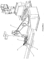
- Figure 1 shows an integrated system for performing primal cuts and then processing the saddle portions and fore-quarters at a number of stations matched to the processing room capacity.
- a carcass Prior to processing by the system shown in figure 1 a carcass may be X-rayed to reveal the internal anatomy of the carcass using a system such as that described in WO2008010732 .
- the anatomical information obtained by X-ray imaging may be associated with a carcass and used in subsequent processing as will be described.
- the system shown in figure 1 includes a fore-quarter primal cutting station 1 which may utilize a carcass cutter as described in the applicant's prior application GB2445277A .
- a saddle cutting station 2 may utilize a carcass cutter as described in the applicant's prior application WO2006135262 .
- a robotic arm 3 transfers a fore-quarter section 4 from fore-quarter primal cutting section 1 to conveyor 5. Whilst robotic arms 3 and 18 are shown in this embodiment simpler purpose-built transfer mechanisms could be employed.
- Robotic arm 3 may place fore-quarter section cut side down so that it sits in a known orientation on conveyor 5.
- Conveyor 5 may be indexed so that robotic arms 6 to 9 may acquire a fore-quarter section at a known position on the conveyor.
- sensors may be used to detect the position of a fore-quarter section and acquire it.
- fore-quarter sections could be deposited into containers on a conveyor adapted to hold the fore-quarter sections in a desired orientation.
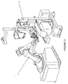
- Robotic arm 6 has spaced apart rests 10 and 11 adapted to be positioned inside the fore-quarter section with the spinal column position between them. Clamps 12 and 13 may be driven towards rests 10 and 11 to clamp the fore-quarter section between them. In use robotic arm 6 is positioned as shown in figure 2 so that it may come from below to position rests 10 and 11 internally against the spinal column and clamps 12 and 13 may then be driven towards rests 10 and 11 to clamp the fore-quarter section to robotic arm 6.
- the fore-quarter section is moved to be imaged by optical imaging apparatus 14 as shown in figure 3 .
- the type of images and the number acquired will depend upon the type of cut to be performed. For a shank cut a single image could be sufficient whereas for other cuts it is preferable that a number of images are obtained and a three dimensional or at least a pseudo three dimensional model is developed.
- One preferred approach is to rotate the fore-quarter section through four 90 degree rotations so as to obtain two dimensional images from four sides.
- These images and the previously acquired X-ray images may be stored in control system 17 which may be a centralised or distributed control system. From these images a three dimensional or at least a pseudo three dimensional model may be developed and cutting paths calculated by control system 17 based on the model.
- X-ray imaging information previously acquired may be used alone or in combination with optical imaging to determine cutting paths for certain cuts.
- the imaging apparatus may project structured light onto the fore-quarter section and multiple images may be acquired to develop a true three dimensional model. To achieve this a laser line may scan across the fore-quarter section with images captured at regular intervals to acquire a true three dimensional image in each orientation.
- a datum referencing device 15 in the form of three orthogonally disposed reference points (balls in this case) may be attached to the end of robotic arm 6 so that the images captured by imaging apparatus 14 may be referenced to the robotic arm.
- the robotic arm 6 moves the fore-quarter section with respect to the blade of a bandsaw 16 to perform any or all of a knuckle cut, neck cut, brisket cut, shank cut, vertebrae split, and any other desired cut.
- the bandsaw may be rotatable through 90 degrees to facilitate the vertebrae split.
- Robotic transfer arm 18 transfers a saddle section from saddle primal station 2 to a support 19.
- Support 19 has spaced apart rods 20 and 21 to support the spinal column therebetween.
- a number of such supports 19 are advanced along track 22 to supply respective saddle cutting stations 23 to 26.
- As the supports are advanced each end of the saddle section is imaged by cameras 27 and 28 and the images supplied to control system 17.
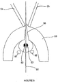
- a probe 29 it inserted into spinal column 30 of saddle section 31 and supplies pressurized fluid into the spinal column to urge the spinal cord along the spinal column.
- a cup 32 is placed over the other end of the spinal column and a vacuum is applied to suck out the spinal cord.
- pressurized fluid at one end and suction at the other has been found to be effective to remove the spinal cord without requiring the spinal column to be cut.
- the probe 29 and cup 32 may be positioned according to standard anatomical positioning for a particular species where supports 20 and 21 centralise the spinal column to an acceptable tolerance or alternatively they may be positioned utilizing imaging information from cameras 27 and 28 and suitable positioning mechanisms.
- support 19 advances to a saddle cutting station, station 23 in this case as shown in figure 7 .
- the saddle section 31 is then transferred from rails 20 and 21 to rails 33 and 34 by pusher 35 pushing saddle section 31 from behind to the required position for a cross cut to be performed.
- the cross cut may be calculated based on X-ray information so as to separate the rack and loin at the best location based on the positions of the bones.
- the saddle section 31 When the saddle section 31 is in the desired position it may be held via a plurality of grippers 36 to 41 actuated by hydraulic or pneumatic rams 42 to 48 which hold the ribs of saddle section 31 against bar 49 so as to firmly hold the saddle section 31 during cross and flap cuts.
- a similar gripping arrangement is provided on the opposite side. The use of multiple grippers has been found to hold the ribs of the flaps more effectively than a single gripper.
- a cross cut is performed by moving a cutting blade 50 attached to robotic arm 51 across the saddle section 31.
- the saddle section has been placed in the correct position for the cut by pusher 35 based upon X-ray information obtained before processing.
- a flap cut is then performed, as shown in figure 8 , by manipulating cutting blade 50 to a desired height via robotic arm 51 according to a cutting path determined by locating the eye fillet from the images obtained by cameras 27 and 28.
- a vertebrae cut is performed as shown in figures 5 and 9 by inserting a split pin having tines 52 and 53 into the spinal column of a saddle subsection 59 (after the cross and flap cuts) and lowering locators 54 and 55 to vertically orient feather bones 56.
- a similar split is inserted in the other end.
- the split pins and locators are then advanced to draw saddle subsection 59 through bandsaw 60 with the blade passing between the tines 52 and 53 (and the pair at the other end) and locators 54 and 55. In this way the saddle subsection may be accurately cut along the middle of the spinal column.
- FIG 11 shows carcass portions in dashed outline overlaying the system shown in figure 10 to illustrate its operation.
- Rotary carousel 61 has four support arms 63 to 66, each having a pair of spaced apart pairs of support rails 67 and 68.
- the spine of a carcass portion locates between the support rails to position a carcass portion in a desired orientation and position.
- the carousel 61 is rotated 90° anticlockwise between processing operations so that each support arm moves to the next processing station.
- support arm 63 is shown at the first processing station where a carcass 81 is imaged by cameras 69 and 70 at either end of the carcass. Further imaging from different perspectives, including X-ray imaging, may be performed to assist cut path calculation. This information is supplied to controller 80 and is used in subsequent processing.
- the cut specifications e.g. flap cut height etc.
- Carcass portion 82 has been imaged and spinal cord removal devices 71 and 72 are positioned based on imaging information supplied to controller 80. These devices operate generally in the manner described in relation to figure 6 .
- Carcass 83 is cut into the rack saddle and shortloin saddle by circular cutting blades 73 and 74 at the third station.
- Carcass portions 84 and 85 are transferred from support arm 66 to spaced apart rails 75 and 76 at the forth station and may be transferred therealong by pushers, conveyor belts or the like. Throughout processing on the rotary carousel the carcass maintains a known geometric orientation to the processing apparatus at each processing station. When the carcass is transferred to the rails the pushers locate the end of the carcass to maintain a known geometric reference for further processing.
- the carcass portions may be continuously advanced along linear conveyor 62 and processed as they move or may be stopped for processing at certain locations or a combination of both.
- Carcass portion 86 may be advanced through rotary cutter blades 77 and 78 to perform brisket and or flap cuts or carcass portion 86 may be held in a stationary position and apparatus of the type shown in figure 7 may be employed to perform these cuts.
- Carcass portion 87 may be advanced through circular cutting blade 79 to perform a cut along the spinal cord or carcass 87 may be held stationary and the blade 79 moved relative to carcass 87.
- Figure 12 shows an arrangement that may be used to perform a spinal cut.
- a pair of spaced apart guide rods 88 and 89 have a gap therebetween to accommodate a blade, in this case a bandsaw blade 90.
- Rods 88 and 89 may be long enough to pass through an entire spinal cavity and serve to guide blade 90 along the spinal column.
- Robotic processing avoids labour related expenses and allows greater flexibility in operating schedules.
- multiple processing steps may be performed without requiring re-indexing of the carcass portion position and orientation with respect to processing equipment.
- cutting paths may be easily determined with respect to the robotic arm without requiring indexing of image information to a robotic arm where a carcass portion is acquired after imaging.
Landscapes
- Engineering & Computer Science (AREA)
- Life Sciences & Earth Sciences (AREA)
- Food Science & Technology (AREA)
- Chemical & Material Sciences (AREA)
- Health & Medical Sciences (AREA)
- Analytical Chemistry (AREA)
- General Health & Medical Sciences (AREA)
- General Engineering & Computer Science (AREA)
- Zoology (AREA)
- Physics & Mathematics (AREA)
- Automation & Control Theory (AREA)
- Biochemistry (AREA)
- Robotics (AREA)
- General Physics & Mathematics (AREA)
- Immunology (AREA)
- Pathology (AREA)
- Wood Science & Technology (AREA)
- Medicinal Chemistry (AREA)
- Processing Of Meat And Fish (AREA)
- Analysing Materials By The Use Of Radiation (AREA)
Description
- This invention relates to automated methods of cutting an animal carcass and apparatus therefor.
- There is a general need to automate the processing of animal carcasses into required cuts. The manual butchering of animal carcasses requires skill and judgement in the manipulation of both meat and tools. With skilled staff manual butchering methods are able to produce a relatively high standard of butchered meat product. However, these methods can be time consuming and a considerable amount of training is required to achieve good results. Furthermore, the skill and judgement of the butcher can falter, resulting in an inaccurately butchered meat product and reduced yield or injury to the butcher. Human contact with the carcass also increases the risk of bacterial contamination of the meat product. Manual processing is also costly and working hours may be inflexible.
- There has therefore been an effort to automate the butchering of animal carcasses, particularly in large-scale commercial slaughtering/butchering operations. Automated carcass cutting methods have reduced butchering time and butcher injury. However, such systems have been expensive and are typically only capable of performing a limited number of the required processing operations, require transfer between manual and automated processes and are often not adapted to take into account variations between different animal carcasses. Such systems may also create processing bottlenecks - particularly where manual processing cannot be performed at the rate of automated processing.
- A significant problem preventing the full automation of animal carcass cutting operations has been the absence of an end to end system capable of performing all major processing cuts. Prior systems have not been truly integrated so that product and information flows with processing. Whilst X-ray and vision systems have been employed these have not been integrated in an end to end system.
- It is an object of the present invention to provide meat processing methods and apparatus overcoming at least some of these disadvantages or to at least provide the public with a useful choice.
-
US 5334084 discloses a method and device for mechanically drawing slaughtered poultry. A method and device for mechanical removal of the viscera package from the belly cavity of slaughtered poultry hanging by the legs from hooks which are moved in a conveyor along a drawing device are disclosed. -
US 7285040 discloses a method for de-rinding and trimming a piece of meat or a piece of slaughtered animal. A device and a method are proposed for de-rinding or trimming a piece of meat or piece of a slaughtered animal, in which an arrangement device for the arrangement of the piece, an industrial robot with a manipulator arm and a sensor system, which detects the part that is to be separated, are provided. - The present invention provides therefore a method and an apparatus of processing a carcass portion according to
claims - The accompanying drawings which are incorporated in and constitute part of the specification, illustrate embodiments of the invention and, together with the general description of the invention given above, and the detailed description of embodiments given below, serve to explain the principles of the invention.
- Figure 1
- shows a plan view of a meat processing system including primal cutting stations and fore-quarter and saddle cutting stations.
- Figure 2
- shows a perspective view of a fore-quarter cutting station with the robotic arm acquiring a fore-quarter section.
- Figure 3
- shows a perspective view of a fore-quarter cutting station with the fore-quarter section being imaged.
- Figure 4
- shows a perspective view of a fore-quarter cutting station with the fore-quarter section being cut.
- Figure 5
- shows a perspective view of a saddle cutting station.
- Figure 6
- shows a schematic diagram of a system for removing a spinal cord.
- Figure 7
- shows an enlarged view of the saddle cutting station shown in
figure 5 performing a cross cut. - Figure 8
- shows an enlarged view of the saddle cutting station shown in
figure 5 performing a flap cut. - Figure 9
- shows a method for performing a vertebrae cut.
- Figure 10
- shows a meat processing system employing a rotary carousel and linear conveyor.
- Figure 11
- shows a carcass portion being processed by the meat processing system shown in
figure 10 . - Figure 12
- shows a guide and saw arrangement for performing a vertebrae cut.
-
Figure 1 shows an integrated system for performing primal cuts and then processing the saddle portions and fore-quarters at a number of stations matched to the processing room capacity. Prior to processing by the system shown infigure 1 a carcass may be X-rayed to reveal the internal anatomy of the carcass using a system such as that described inWO2008010732 . The anatomical information obtained by X-ray imaging may be associated with a carcass and used in subsequent processing as will be described.
The system shown infigure 1 includes a fore-quarterprimal cutting station 1 which may utilize a carcass cutter as described in the applicant's prior applicationGB2445277A WO2006135262 . A robotic arm 3 transfers a fore-quarter section 4 from fore-quarterprimal cutting section 1 to conveyor 5. Whilstrobotic arms 3 and 18 are shown in this embodiment simpler purpose-built transfer mechanisms could be employed. Robotic arm 3 may place fore-quarter section cut side down so that it sits in a known orientation on conveyor 5. Conveyor 5 may be indexed so that robotic arms 6 to 9 may acquire a fore-quarter section at a known position on the conveyor. Alternatively sensors may be used to detect the position of a fore-quarter section and acquire it. Alternatively fore-quarter sections could be deposited into containers on a conveyor adapted to hold the fore-quarter sections in a desired orientation. - Referring now to
figure 2 a fore-quarter cutting station is shown in more detail. Robotic arm 6 has spaced apartrests 10 and 11 adapted to be positioned inside the fore-quarter section with the spinal column position between them.Clamps rests 10 and 11 to clamp the fore-quarter section between them. In use robotic arm 6 is positioned as shown infigure 2 so that it may come from below to position rests 10 and 11 internally against the spinal column and clamps 12 and 13 may then be driven towards rests 10 and 11 to clamp the fore-quarter section to robotic arm 6. - Once the fore-quarter section is firmly secured to robotic arm 6 the fore-quarter section is moved to be imaged by
optical imaging apparatus 14 as shown infigure 3 . The type of images and the number acquired will depend upon the type of cut to be performed. For a shank cut a single image could be sufficient whereas for other cuts it is preferable that a number of images are obtained and a three dimensional or at least a pseudo three dimensional model is developed. One preferred approach is to rotate the fore-quarter section through four 90 degree rotations so as to obtain two dimensional images from four sides. These images and the previously acquired X-ray images may be stored incontrol system 17 which may be a centralised or distributed control system. From these images a three dimensional or at least a pseudo three dimensional model may be developed and cutting paths calculated bycontrol system 17 based on the model. X-ray imaging information previously acquired may be used alone or in combination with optical imaging to determine cutting paths for certain cuts. - The imaging apparatus may project structured light onto the fore-quarter section and multiple images may be acquired to develop a true three dimensional model. To achieve this a laser line may scan across the fore-quarter section with images captured at regular intervals to acquire a true three dimensional image in each orientation.
- A
datum referencing device 15 in the form of three orthogonally disposed reference points (balls in this case) may be attached to the end of robotic arm 6 so that the images captured by imagingapparatus 14 may be referenced to the robotic arm. - After imaging the robotic arm 6 moves the fore-quarter section with respect to the blade of a
bandsaw 16 to perform any or all of a knuckle cut, neck cut, brisket cut, shank cut, vertebrae split, and any other desired cut. Depending upon the arrangement the bandsaw may be rotatable through 90 degrees to facilitate the vertebrae split. - It is to be appreciated that from the fore-quarter section being acquired by robotic arm 6 it is continuously held in a fixed relationship to robotic arm 6 throughout imaging and multiple cutting operations; thus avoiding the need to re-index the position of the fore-quarter section with respect to the robotic arm which would occur were the fore-quarter section to be transferred between the various operations.
- Referring now to
figures 1 and5 a saddle cutting station is shown.Robotic transfer arm 18 transfers a saddle section from saddle primal station 2 to asupport 19.Support 19 has spaced apartrods such supports 19 are advanced alongtrack 22 to supply respectivesaddle cutting stations 23 to 26. As the supports are advanced each end of the saddle section is imaged bycameras system 17. - After imaging the spinal cord is removed as shown schematically in
figure 6 . Aprobe 29 it inserted intospinal column 30 ofsaddle section 31 and supplies pressurized fluid into the spinal column to urge the spinal cord along the spinal column. Acup 32 is placed over the other end of the spinal column and a vacuum is applied to suck out the spinal cord. The combination of pressurized fluid at one end and suction at the other has been found to be effective to remove the spinal cord without requiring the spinal column to be cut. - The
probe 29 andcup 32 may be positioned according to standard anatomical positioning for a particular species where supports 20 and 21 centralise the spinal column to an acceptable tolerance or alternatively they may be positioned utilizing imaging information fromcameras - Once the spinal column is removed
support 19 advances to a saddle cutting station,station 23 in this case as shown infigure 7 . Thesaddle section 31 is then transferred fromrails rails pusher 35 pushingsaddle section 31 from behind to the required position for a cross cut to be performed. The cross cut may be calculated based on X-ray information so as to separate the rack and loin at the best location based on the positions of the bones. - When the
saddle section 31 is in the desired position it may be held via a plurality of grippers 36 to 41 actuated by hydraulic or pneumatic rams 42 to 48 which hold the ribs ofsaddle section 31 against bar 49 so as to firmly hold thesaddle section 31 during cross and flap cuts. A similar gripping arrangement is provided on the opposite side. The use of multiple grippers has been found to hold the ribs of the flaps more effectively than a single gripper. As shown infigure 7 a cross cut is performed by moving a cutting blade 50 attached torobotic arm 51 across thesaddle section 31. The saddle section has been placed in the correct position for the cut bypusher 35 based upon X-ray information obtained before processing. A flap cut is then performed, as shown infigure 8 , by manipulating cutting blade 50 to a desired height viarobotic arm 51 according to a cutting path determined by locating the eye fillet from the images obtained bycameras - Finally a vertebrae cut is performed as shown in
figures 5 and9 by inserting a splitpin having tines locators feather bones 56. A similar split is inserted in the other end. The split pins and locators are then advanced to drawsaddle subsection 59 throughbandsaw 60 with the blade passing between thetines 52 and 53 (and the pair at the other end) andlocators - Referring now to
figures 10 and11 a meat processing system employing arotary carousel 61 and alinear conveyor 62 will be described.Figure 11 shows carcass portions in dashed outline overlaying the system shown infigure 10 to illustrate its operation.Rotary carousel 61 has foursupport arms 63 to 66, each having a pair of spaced apart pairs of support rails 67 and 68. As shown infigure 9 the spine of a carcass portion locates between the support rails to position a carcass portion in a desired orientation and position. Thecarousel 61 is rotated 90° anticlockwise between processing operations so that each support arm moves to the next processing station. - In
figure 10 support arm 63 is shown at the first processing station where acarcass 81 is imaged bycameras controller 80 and is used in subsequent processing. The cut specifications (e.g. flap cut height etc.) may be entered by a user intocontroller 80 and different cuts and cut specifications may be utilised for different carcasses.Carcass portion 82 has been imaged and spinalcord removal devices controller 80. These devices operate generally in the manner described in relation tofigure 6 .Carcass 83 is cut into the rack saddle and shortloin saddle bycircular cutting blades Carcass portions support arm 66 to spaced apart rails 75 and 76 at the forth station and may be transferred therealong by pushers, conveyor belts or the like. Throughout processing on the rotary carousel the carcass maintains a known geometric orientation to the processing apparatus at each processing station. When the carcass is transferred to the rails the pushers locate the end of the carcass to maintain a known geometric reference for further processing. - The carcass portions may be continuously advanced along
linear conveyor 62 and processed as they move or may be stopped for processing at certain locations or a combination of both.Carcass portion 86 may be advanced throughrotary cutter blades carcass portion 86 may be held in a stationary position and apparatus of the type shown infigure 7 may be employed to perform these cuts.Carcass portion 87 may be advanced throughcircular cutting blade 79 to perform a cut along the spinal cord orcarcass 87 may be held stationary and theblade 79 moved relative tocarcass 87. -
Figure 12 shows an arrangement that may be used to perform a spinal cut. A pair of spaced apart guiderods bandsaw blade 90.Rods blade 90 along the spinal column.
There are thus provided an integrated automated meat processing system allowing fully automated end to end processing. By allowing scalability of sub-processing stations to the desired processing rate equipment utilization may be optimized and bottlenecks avoided. As information flows with processing it may be used and combined with additional information at each stage of processing. This arrangement also provides enhanced traceability of product to each sub-processing station.
Fully automated processing provides increased accuracy resulting in enhanced product yield and value. This may be achieved using X-ray and optical information, optimized cutting path calculation and robotic accuracy. Robotic processing avoids labour related expenses and allows greater flexibility in operating schedules.
By minimizing product transfer multiple processing steps may be performed without requiring re-indexing of the carcass portion position and orientation with respect to processing equipment. By imaging a carcass portion whilst it is held by a robotic arm cutting paths may be easily determined with respect to the robotic arm without requiring indexing of image information to a robotic arm where a carcass portion is acquired after imaging.
There is also provided a method of effectively removing the spinal cord without requiring splitting of the spinal column.
Claims (14)
- A method of processing a carcass portion (4) including the steps of:a. holding the carcass portion (4)b. imaging the carcass portion (4);c. determining one or more cut paths based on the imaging; andd. moving the carcass portion (4) with respect to a cutting tool (16) to cut the carcass portion (4) along the one or more cut paths, wherein the carcass portion (4) is held by a robotic arm (6) during imaging and cutting.
- A method as claimed in claim 1 wherein the carcass portion (4) is moved to a plurality of positions to obtain multiple images of the carcass from different perspectives.
- A method as claimed in claim 2 wherein a three dimensional image of the carcass portion (4) is generated from the images obtained.
- A method as claimed in any one of the preceding claims wherein structured light is scanned over the carcass portion (4) as the images are obtained.
- A method as claimed in any one of the preceding claims wherein a datum referencing element (15) is provided on the robotic arm (6) so that, when images of the carcass portion (4) and datum referencing element (15) are captured, the datum referencing element (15) is used to determine the position and orientation of the carcass portion (4) with respect to the robotic arm (6).
- A method as claimed in claim 5 wherein the datum referencing element (15) consists of 3 reference points orthogonally disposed with respect to the robotic arm (6).
- A method as claimed in any one of the preceding claims wherein an X-ray image of the carcass portion (4) is obtained prior to processing using the robotic arm (6) and the X-ray image is combined with imaging of the carcass portion (4) whilst held by the robotic arm (6) to form a composite model of the carcass portion (4).
- A method as claimed in claim 7 wherein cut paths are determined based on the composite model.
- A method as claimed in any one of the preceding claims wherein multiple cuts are performed whilst the carcass portion (4) is continuously held by the robotic arm (6).
- A method as claimed in any one of the preceding claims wherein the carcass portion (4) is held stationary whilst cutting tools are moved relative to the carcass portion (4) to cut the carcass portion (4).
- A method as claimed in claim 9 or claim 10 wherein geometric reference is maintained between the carcass portion (4) and the cutting tool (16) to perform the sequence of cuts based on the imaging information.
- A method as claimed in any one of the preceding claims wherein the imaging includes optical imaging.
- A method as claimed in any one of claims 1 to 11 wherein the imaging includes X-ray imaging.
- A carcass cutting apparatus including:a. a robotic arm (6) having grippers configured to grip a portion of a carcass (4);b. an imaging system (14) configured to image the portion of the carcass;c. a control system (17) configured to determine one or more cut paths based on images from the imaging system (14); andd. a cutting tool (16) configured to cut a carcass portion when the robotic arm moves the carcass portion with respect to the cutting tool to cut the carcass along the one or more cut paths,
wherein the control system (17) is configured to control the robotic arm (6) to hold the carcass portion (4) during imaging and cutting operations.
Priority Applications (1)
| Application Number | Priority Date | Filing Date | Title |
|---|---|---|---|
| PL10759094T PL2413702T3 (en) | 2009-04-03 | 2010-04-01 | Carcass cutting method and apparatus |
Applications Claiming Priority (2)
| Application Number | Priority Date | Filing Date | Title |
|---|---|---|---|
| NZ57607009 | 2009-04-03 | ||
| PCT/NZ2010/000062 WO2010114397A1 (en) | 2009-04-03 | 2010-04-01 | Carcass cutting methods and apparatus |
Publications (3)
| Publication Number | Publication Date |
|---|---|
| EP2413702A1 EP2413702A1 (en) | 2012-02-08 |
| EP2413702A4 EP2413702A4 (en) | 2017-03-29 |
| EP2413702B1 true EP2413702B1 (en) | 2018-05-30 |
Family
ID=42828507
Family Applications (1)
| Application Number | Title | Priority Date | Filing Date |
|---|---|---|---|
| EP10759094.5A Active EP2413702B1 (en) | 2009-04-03 | 2010-04-01 | Carcass cutting method and apparatus |
Country Status (11)
| Country | Link |
|---|---|
| US (2) | US9091673B2 (en) |
| EP (1) | EP2413702B1 (en) |
| CN (2) | CN102421297B (en) |
| AU (1) | AU2010232016B2 (en) |
| BR (1) | BRPI1015107B1 (en) |
| CA (2) | CA2892802A1 (en) |
| DK (1) | DK2413702T3 (en) |
| ES (1) | ES2685312T3 (en) |
| MX (1) | MX2011010360A (en) |
| PL (1) | PL2413702T3 (en) |
| WO (1) | WO2010114397A1 (en) |
Families Citing this family (41)
| Publication number | Priority date | Publication date | Assignee | Title |
|---|---|---|---|---|
| PL2869704T3 (en) * | 2012-07-04 | 2019-01-31 | Marel Meat B.V. | System for conveying carcasses or carcass parts of quadruped slaughter animals |
| BR112015000905A2 (en) * | 2012-08-31 | 2017-06-27 | Jarvis Products | carcass stabilizer, and method for stabilizing a carcass |
| CA3019818A1 (en) | 2014-05-01 | 2015-11-05 | Jarvis Products Corporation | Robotic carcass processing method and system |
| WO2016045683A1 (en) * | 2014-09-23 | 2016-03-31 | Marel A/S | A method and a device for automatically cutting meat products such as beef tenderloin into portions |
| MY170688A (en) * | 2015-03-23 | 2019-08-26 | Nienstedt Gmbh | Method of producing tuna fish pieces |
| DK178447B1 (en) | 2015-06-10 | 2016-02-29 | Ihfood As | Removing the spinal column from a half-carcass of a slaughtered animal |
| DE102015111448B3 (en) * | 2015-07-15 | 2016-05-25 | Nordischer Maschinenbau Rud. Baader Gmbh + Co. Kg | Apparatus and method for removing meatbones from a fish fillet |
| US10721947B2 (en) * | 2016-07-29 | 2020-07-28 | John Bean Technologies Corporation | Apparatus for acquiring and analysing product-specific data for products of the food processing industry as well as a system comprising such an apparatus and a method for processing products of the food processing industry |
| US10654185B2 (en) | 2016-07-29 | 2020-05-19 | John Bean Technologies Corporation | Cutting/portioning using combined X-ray and optical scanning |
| NL2018150B1 (en) | 2017-01-10 | 2018-07-25 | Humboldt Bv | Method and device for processing carcasses of livestock along the spine |
| US10682018B2 (en) * | 2017-09-02 | 2020-06-16 | Anas Alfarra | Automated food preparation and dispensing |
| PL3545769T3 (en) * | 2017-10-06 | 2021-09-27 | Mayekawa Mfg. Co., Ltd. | System for loading leg meat on the bone |
| CN108142532A (en) * | 2018-01-09 | 2018-06-12 | 傅峰峰 | A kind of domestic animal handles integral machine |
| CN108142533A (en) * | 2018-01-09 | 2018-06-12 | 傅峰峰 | A kind of domestic animal processing unit (plant) |
| GB201810055D0 (en) * | 2018-06-19 | 2018-08-08 | Ishida Europe Ltd | Method and system for processing poultry portions |
| PH12021550342B1 (en) * | 2018-08-16 | 2024-05-24 | Thai Union Group Public Co Ltd | Multi-view imaging system and methods for non-invasive inspection in food processing |
| CN109105451B (en) * | 2018-09-10 | 2020-11-17 | 义乌市安航科技有限公司 | Do not influence first device of inhaling of fish article looks |
| US11375739B2 (en) | 2018-10-10 | 2022-07-05 | MP Equipment, LLC | Method of removing tissue from food product |
| CN113163775B (en) * | 2018-11-22 | 2023-06-27 | 洪堡有限公司 | Method and device for locating and/or handling carcasses and/or carcass parts during slaughter of animals on an industrial scale |
| DK180199B1 (en) * | 2018-12-17 | 2020-08-13 | Teknologisk Inst | Cellular meat production |
| CN111409129A (en) * | 2019-01-07 | 2020-07-14 | 元进庄企业股份有限公司 | Automatic poultry slitting device and method thereof |
| CN109805068B (en) * | 2019-02-28 | 2024-03-15 | 浙江大学舟山海洋研究中心 | An intelligent slicing device and method for squid |
| WO2020210203A1 (en) | 2019-04-08 | 2020-10-15 | Provisur Technologies, Inc. | Apparatus and method for cutting meat products into blocks of meat |
| WO2020212716A1 (en) * | 2019-04-16 | 2020-10-22 | Giannopoulos Panagiotis | Device for the delivery of products processed from fresh fruits and /or vegetables |
| DE102019110313B3 (en) | 2019-04-18 | 2020-07-02 | Provisur Technologies GmbH | Food processing device and corresponding food processing method |
| NL2023065B1 (en) * | 2019-05-03 | 2020-11-30 | Marel Meat Bv | Cutting fore end from hanging half pig carcass. |
| NL2023064B1 (en) * | 2019-05-03 | 2020-11-30 | Marel Meat Bv | A method and an apparatus for processing a half pig carcass part hanging from a carrier. |
| US10881115B1 (en) * | 2019-08-19 | 2021-01-05 | James Ronald Inscho, Jr. | Automated poultry orientation and shackling system |
| CN110604164B (en) * | 2019-11-18 | 2021-05-04 | 华中农业大学 | A sheep skeleton cutting jig |
| AU2020405625C8 (en) * | 2019-12-20 | 2026-05-07 | Scott Automation & Robotics Pty Limited | A meat processing system |
| JP7343905B2 (en) * | 2020-06-30 | 2023-09-13 | 一雄 佐藤 | Boning device |
| CN111958659A (en) * | 2020-07-21 | 2020-11-20 | 福州聚英智能科技有限公司 | Machine vision automatic bone sawing machine based on multi-degree-of-freedom clamping |
| CN111838272B (en) * | 2020-07-21 | 2022-03-15 | 福州聚英智能科技有限公司 | Automatic bone sawing machine for self-positioning of meat blocks |
| WO2022026153A1 (en) * | 2020-07-27 | 2022-02-03 | Cryovac, Llc | Targeting for vacuum-based engagement tools |
| KR102557989B1 (en) * | 2021-05-11 | 2023-07-19 | 기백준 | Automatic neck-bone cutting system for meat |
| CN113575650B (en) * | 2021-07-23 | 2022-05-03 | 华中农业大学 | Livestock carcass air suction fixing and cutting device and method |
| US20230126530A1 (en) | 2021-10-25 | 2023-04-27 | Provisur Technologies, Inc. | Food product gripping assembly for a food product slicing apparatus |
| CN114176104B (en) * | 2021-11-23 | 2023-07-14 | 北京机械工业自动化研究所有限公司 | Device and method for deboning and dividing livestock carcasses |
| CN114287463B (en) * | 2022-01-30 | 2022-11-11 | 华中科技大学 | Automatic poultry carcass cutting production line and processing method thereof |
| JP2025515646A (en) * | 2022-05-12 | 2025-05-20 | マレル・レッド・ミート・ベスローテン・フェンノートシャップ | Spine Treatment Device |
| US20240208098A1 (en) * | 2022-12-21 | 2024-06-27 | Proex Food, Llc | Food imaging and processing systems and methods |
Family Cites Families (32)
| Publication number | Priority date | Publication date | Assignee | Title |
|---|---|---|---|---|
| DK159579C (en) * | 1975-01-10 | 1991-04-29 | Ataliers De Const Mecaniques L | APPARATUS FOR SHARING ANIMAL SUSPENDED BODY OF ANIMALS |
| US4209878A (en) * | 1978-03-20 | 1980-07-01 | Albert Howard C | Automatic meat inspecting and trimming machine and method |
| US4389749A (en) | 1980-12-23 | 1983-06-28 | Korhonen K J | Cutting-up process |
| IE59198B1 (en) * | 1987-03-24 | 1994-05-18 | Passchier Bob | Improvements in meat recovery from carcase sections |
| US4847954A (en) * | 1987-05-12 | 1989-07-18 | The Laitram Corporation | Support apparatus for use in video imaging and processing of transverse fish sections |
| US4875254A (en) * | 1988-03-22 | 1989-10-24 | Design Systems, Inc. | Method and apparatus for automatically cutting food products to predetermined weight or shape |
| FR2672775B1 (en) * | 1991-02-14 | 1993-05-21 | Normaclass Rd | PROCESS FOR THE CLASSIFICATION OF CARCASES OF LARGE CATTLE, CALVES, PIGS OR SHEEP AND DEVICE FOR ITS IMPLEMENTATION. |
| US5205779A (en) * | 1991-09-04 | 1993-04-27 | Texas Beef Group | Method and apparatus for automatically segmenting animal carcasses |
| USRE36664E (en) * | 1991-09-04 | 2000-04-18 | Texas Beef Group | Method and apparatus for automatically segmenting animal carcasses |
| US5334084A (en) | 1991-09-04 | 1994-08-02 | Texas Beef Group | Method and apparatus for automatically trimming fatty tissue from animal carcasses |
| DK171036B1 (en) * | 1993-04-26 | 1996-04-29 | Slagteriernes Forskningsinst | Method and apparatus for fixing carved carcasses on slaughtered pigs at the hind legs |
| US5372540A (en) * | 1993-07-13 | 1994-12-13 | The Laitram Corporation | Robot cutting system |
| ES2106633T3 (en) | 1993-11-26 | 1997-11-01 | British Tech Group | PLUMBING DEVICE FOR POULTRY. |
| NL9402036A (en) * | 1994-12-02 | 1996-07-01 | Stork Protecon Langen Bv | Apparatus and method for making a cut in and in particular removing the spinal cord from an agent. |
| FR2759866B1 (en) * | 1997-02-25 | 1999-09-10 | Ass Nationale Interprofessionn | PROCESS FOR EXTRACTING IN PARTICULAR SPINAL MARROW FROM THE CARCASS OF AN ANIMAL AND DEVICE FOR CARRYING OUT SAID METHOD |
| US6882434B1 (en) * | 1999-04-20 | 2005-04-19 | Formax, Inc. | Automated product profiling apparatus and product slicing system using same |
| US6126536A (en) * | 1999-07-01 | 2000-10-03 | Jarvis Products Corporation | Automated saw for splitting carcasses |
| EP1211944B1 (en) * | 1999-08-27 | 2004-09-29 | K.J. Maskinfabriken A/S | Automatic vision based cutting-up system |
| US6354933B1 (en) * | 2000-05-01 | 2002-03-12 | Centre De Recherche Industrielle Du Quebec | Meat deboning apparatus and method |
| TW564160B (en) * | 2000-07-11 | 2003-12-01 | Nordischer Maschinenbau | Method and apparatus for filleting decapitated, slaughtered fish with their belly cavities opened |
| GB2364894B8 (en) * | 2000-07-19 | 2010-07-07 | Fmc Corp | Three axis portioning method |
| US20020155803A1 (en) * | 2001-04-18 | 2002-10-24 | Tieleman Rudolf J. | Poultry processing machine having carcass locating apparatus |
| DE10150394A1 (en) | 2001-10-08 | 2003-04-17 | Werner Treige | Jet knife cuts and expels nervous tissue from slaughtered cattle vertebral column |
| US6974373B2 (en) * | 2002-08-02 | 2005-12-13 | Geissler Technologies, Llc | Apparatus and methods for the volumetric and dimensional measurement of livestock |
| CA2587006C (en) * | 2002-12-10 | 2013-04-30 | Chep Technology Pty Limited | Automated pallet inspection and repair |
| ATE475319T1 (en) * | 2003-04-04 | 2010-08-15 | Schill Maja Masch | DEVICE FOR DELINDING OR TRIMING A PIECE OF MEAT OR A PIECE OF SLAUGHTER ANIMAL |
| JP2005245348A (en) * | 2004-03-05 | 2005-09-15 | Yasukawa Sangyo:Kk | Automatic feeding device of chicken on chicken-slaughtering line in automatic treating line facility of poultry meat |
| JP4126027B2 (en) * | 2004-04-16 | 2008-07-30 | 食肉生産技術研究組合 | Spinal column removal method and spinal column removal device |
| US7251537B1 (en) * | 2004-12-30 | 2007-07-31 | Fmc Technologies, Inc. | Processing of work piece based on desired end physical criteria |
| GB2421676B (en) * | 2004-12-30 | 2010-03-24 | Fmc Technologies | Portioning apparatus and method |
| GB0512467D0 (en) * | 2005-06-17 | 2005-07-27 | Khodabandehloo Koorosh | Apparatus for cutting meat carcasses |
| NZ548648A (en) * | 2006-07-21 | 2008-10-31 | Robotic Technologies Ltd | X-ray imaging of animal carcass to determine cutting path |
-
2010
- 2010-04-01 US US13/262,828 patent/US9091673B2/en active Active
- 2010-04-01 CN CN201080020754.3A patent/CN102421297B/en active Active
- 2010-04-01 MX MX2011010360A patent/MX2011010360A/en active IP Right Grant
- 2010-04-01 BR BRPI1015107-9A patent/BRPI1015107B1/en active IP Right Grant
- 2010-04-01 CN CN201410136079.0A patent/CN103931728A/en active Pending
- 2010-04-01 ES ES10759094.5T patent/ES2685312T3/en active Active
- 2010-04-01 CA CA2892802A patent/CA2892802A1/en not_active Abandoned
- 2010-04-01 EP EP10759094.5A patent/EP2413702B1/en active Active
- 2010-04-01 CA CA2757406A patent/CA2757406C/en active Active
- 2010-04-01 AU AU2010232016A patent/AU2010232016B2/en active Active
- 2010-04-01 WO PCT/NZ2010/000062 patent/WO2010114397A1/en not_active Ceased
- 2010-04-01 DK DK10759094.5T patent/DK2413702T3/en active
- 2010-04-01 PL PL10759094T patent/PL2413702T3/en unknown
-
2015
- 2015-06-23 US US14/747,765 patent/US20150320058A1/en not_active Abandoned
Non-Patent Citations (1)
| Title |
|---|
| None * |
Also Published As
| Publication number | Publication date |
|---|---|
| US20120040597A1 (en) | 2012-02-16 |
| DK2413702T3 (en) | 2018-09-03 |
| CA2757406A1 (en) | 2010-10-07 |
| CN102421297B (en) | 2015-11-25 |
| US9091673B2 (en) | 2015-07-28 |
| ES2685312T3 (en) | 2018-10-08 |
| CA2757406C (en) | 2015-10-27 |
| BRPI1015107B1 (en) | 2019-02-26 |
| CN102421297A (en) | 2012-04-18 |
| WO2010114397A1 (en) | 2010-10-07 |
| EP2413702A4 (en) | 2017-03-29 |
| AU2010232016B2 (en) | 2015-05-07 |
| PL2413702T3 (en) | 2018-10-31 |
| CA2892802A1 (en) | 2010-10-07 |
| AU2010232016A1 (en) | 2011-10-20 |
| BRPI1015107A2 (en) | 2016-04-26 |
| CN103931728A (en) | 2014-07-23 |
| US20150320058A1 (en) | 2015-11-12 |
| MX2011010360A (en) | 2012-04-30 |
| EP2413702A1 (en) | 2012-02-08 |
Similar Documents
| Publication | Publication Date | Title |
|---|---|---|
| DK2413702T3 (en) | METHODS AND DEVICE FOR CUTTING ANIMAL BODY | |
| AU2019384619B2 (en) | Method and device for positioning and/or handling carcasses and/or carcass parts during the slaughter of animals on an industrial scale | |
| US9717257B2 (en) | System and method for processing slaughtered animals and/or parts thereof | |
| EP3537883B1 (en) | Method and device for processing carcasses of livestock along the spine | |
| AU2015203162A1 (en) | Carcass cutting methods and apparatus | |
| WO2026102545A1 (en) | Pork neck bone cutting assembly and method and meat processing system | |
| NL2003968C2 (en) | System and method for processing slaughtered animals and/or parts thereof. | |
| BR122015030061B1 (en) | SYSTEM AND METHOD FOR PROCESSING A CARCASS OR PART OF A CARCASS FROM A SWINE, BOVINE, OVINE OR CAPRINE ANIMAL FOR SLAUGHTER |
Legal Events
| Date | Code | Title | Description |
|---|---|---|---|
| PUAI | Public reference made under article 153(3) epc to a published international application that has entered the european phase |
Free format text: ORIGINAL CODE: 0009012 |
|
| 17P | Request for examination filed |
Effective date: 20111028 |
|
| AK | Designated contracting states |
Kind code of ref document: A1 Designated state(s): AT BE BG CH CY CZ DE DK EE ES FI FR GB GR HR HU IE IS IT LI LT LU LV MC MK MT NL NO PL PT RO SE SI SK SM TR |
|
| DAX | Request for extension of the european patent (deleted) | ||
| RA4 | Supplementary search report drawn up and despatched (corrected) |
Effective date: 20170227 |
|
| RIC1 | Information provided on ipc code assigned before grant |
Ipc: G01N 33/12 20060101ALI20170221BHEP Ipc: A22B 7/00 20060101AFI20170221BHEP Ipc: A22C 18/00 20060101ALI20170221BHEP Ipc: G01N 23/00 20060101ALI20170221BHEP Ipc: A22C 17/02 20060101ALI20170221BHEP |
|
| GRAP | Despatch of communication of intention to grant a patent |
Free format text: ORIGINAL CODE: EPIDOSNIGR1 |
|
| STAA | Information on the status of an ep patent application or granted ep patent |
Free format text: STATUS: GRANT OF PATENT IS INTENDED |
|
| INTG | Intention to grant announced |
Effective date: 20171109 |
|
| GRAS | Grant fee paid |
Free format text: ORIGINAL CODE: EPIDOSNIGR3 |
|
| GRAA | (expected) grant |
Free format text: ORIGINAL CODE: 0009210 |
|
| STAA | Information on the status of an ep patent application or granted ep patent |
Free format text: STATUS: THE PATENT HAS BEEN GRANTED |
|
| AK | Designated contracting states |
Kind code of ref document: B1 Designated state(s): AT BE BG CH CY CZ DE DK EE ES FI FR GB GR HR HU IE IS IT LI LT LU LV MC MK MT NL NO PL PT RO SE SI SK SM TR |
|
| REG | Reference to a national code |
Ref country code: GB Ref legal event code: FG4D |
|
| REG | Reference to a national code |
Ref country code: CH Ref legal event code: EP |
|
| REG | Reference to a national code |
Ref country code: AT Ref legal event code: REF Ref document number: 1002634 Country of ref document: AT Kind code of ref document: T Effective date: 20180615 |
|
| REG | Reference to a national code |
Ref country code: DE Ref legal event code: R096 Ref document number: 602010050956 Country of ref document: DE |
|
| REG | Reference to a national code |
Ref country code: IE Ref legal event code: FG4D |
|
| REG | Reference to a national code |
Ref country code: DK Ref legal event code: T3 Effective date: 20180829 |
|
| REG | Reference to a national code |
Ref country code: NL Ref legal event code: FP |
|
| REG | Reference to a national code |
Ref country code: ES Ref legal event code: FG2A Ref document number: 2685312 Country of ref document: ES Kind code of ref document: T3 Effective date: 20181008 |
|
| REG | Reference to a national code |
Ref country code: LT Ref legal event code: MG4D |
|
| PG25 | Lapsed in a contracting state [announced via postgrant information from national office to epo] |
Ref country code: LT Free format text: LAPSE BECAUSE OF FAILURE TO SUBMIT A TRANSLATION OF THE DESCRIPTION OR TO PAY THE FEE WITHIN THE PRESCRIBED TIME-LIMIT Effective date: 20180530 Ref country code: NO Free format text: LAPSE BECAUSE OF FAILURE TO SUBMIT A TRANSLATION OF THE DESCRIPTION OR TO PAY THE FEE WITHIN THE PRESCRIBED TIME-LIMIT Effective date: 20180830 Ref country code: FI Free format text: LAPSE BECAUSE OF FAILURE TO SUBMIT A TRANSLATION OF THE DESCRIPTION OR TO PAY THE FEE WITHIN THE PRESCRIBED TIME-LIMIT Effective date: 20180530 Ref country code: SE Free format text: LAPSE BECAUSE OF FAILURE TO SUBMIT A TRANSLATION OF THE DESCRIPTION OR TO PAY THE FEE WITHIN THE PRESCRIBED TIME-LIMIT Effective date: 20180530 Ref country code: BG Free format text: LAPSE BECAUSE OF FAILURE TO SUBMIT A TRANSLATION OF THE DESCRIPTION OR TO PAY THE FEE WITHIN THE PRESCRIBED TIME-LIMIT Effective date: 20180830 Ref country code: CY Free format text: LAPSE BECAUSE OF FAILURE TO SUBMIT A TRANSLATION OF THE DESCRIPTION OR TO PAY THE FEE WITHIN THE PRESCRIBED TIME-LIMIT Effective date: 20180530 |
|
| PG25 | Lapsed in a contracting state [announced via postgrant information from national office to epo] |
Ref country code: HR Free format text: LAPSE BECAUSE OF FAILURE TO SUBMIT A TRANSLATION OF THE DESCRIPTION OR TO PAY THE FEE WITHIN THE PRESCRIBED TIME-LIMIT Effective date: 20180530 Ref country code: GR Free format text: LAPSE BECAUSE OF FAILURE TO SUBMIT A TRANSLATION OF THE DESCRIPTION OR TO PAY THE FEE WITHIN THE PRESCRIBED TIME-LIMIT Effective date: 20180831 Ref country code: LV Free format text: LAPSE BECAUSE OF FAILURE TO SUBMIT A TRANSLATION OF THE DESCRIPTION OR TO PAY THE FEE WITHIN THE PRESCRIBED TIME-LIMIT Effective date: 20180530 |
|
| REG | Reference to a national code |
Ref country code: AT Ref legal event code: MK05 Ref document number: 1002634 Country of ref document: AT Kind code of ref document: T Effective date: 20180530 |
|
| PG25 | Lapsed in a contracting state [announced via postgrant information from national office to epo] |
Ref country code: AT Free format text: LAPSE BECAUSE OF FAILURE TO SUBMIT A TRANSLATION OF THE DESCRIPTION OR TO PAY THE FEE WITHIN THE PRESCRIBED TIME-LIMIT Effective date: 20180530 Ref country code: EE Free format text: LAPSE BECAUSE OF FAILURE TO SUBMIT A TRANSLATION OF THE DESCRIPTION OR TO PAY THE FEE WITHIN THE PRESCRIBED TIME-LIMIT Effective date: 20180530 Ref country code: RO Free format text: LAPSE BECAUSE OF FAILURE TO SUBMIT A TRANSLATION OF THE DESCRIPTION OR TO PAY THE FEE WITHIN THE PRESCRIBED TIME-LIMIT Effective date: 20180530 Ref country code: SK Free format text: LAPSE BECAUSE OF FAILURE TO SUBMIT A TRANSLATION OF THE DESCRIPTION OR TO PAY THE FEE WITHIN THE PRESCRIBED TIME-LIMIT Effective date: 20180530 Ref country code: CZ Free format text: LAPSE BECAUSE OF FAILURE TO SUBMIT A TRANSLATION OF THE DESCRIPTION OR TO PAY THE FEE WITHIN THE PRESCRIBED TIME-LIMIT Effective date: 20180530 |
|
| PG25 | Lapsed in a contracting state [announced via postgrant information from national office to epo] |
Ref country code: SM Free format text: LAPSE BECAUSE OF FAILURE TO SUBMIT A TRANSLATION OF THE DESCRIPTION OR TO PAY THE FEE WITHIN THE PRESCRIBED TIME-LIMIT Effective date: 20180530 |
|
| REG | Reference to a national code |
Ref country code: DE Ref legal event code: R097 Ref document number: 602010050956 Country of ref document: DE |
|
| PLBE | No opposition filed within time limit |
Free format text: ORIGINAL CODE: 0009261 |
|
| STAA | Information on the status of an ep patent application or granted ep patent |
Free format text: STATUS: NO OPPOSITION FILED WITHIN TIME LIMIT |
|
| 26N | No opposition filed |
Effective date: 20190301 |
|
| PG25 | Lapsed in a contracting state [announced via postgrant information from national office to epo] |
Ref country code: SI Free format text: LAPSE BECAUSE OF FAILURE TO SUBMIT A TRANSLATION OF THE DESCRIPTION OR TO PAY THE FEE WITHIN THE PRESCRIBED TIME-LIMIT Effective date: 20180530 |
|
| REG | Reference to a national code |
Ref country code: CH Ref legal event code: PL |
|
| PG25 | Lapsed in a contracting state [announced via postgrant information from national office to epo] |
Ref country code: MC Free format text: LAPSE BECAUSE OF FAILURE TO SUBMIT A TRANSLATION OF THE DESCRIPTION OR TO PAY THE FEE WITHIN THE PRESCRIBED TIME-LIMIT Effective date: 20180530 Ref country code: LU Free format text: LAPSE BECAUSE OF NON-PAYMENT OF DUE FEES Effective date: 20190401 |
|
| PG25 | Lapsed in a contracting state [announced via postgrant information from national office to epo] |
Ref country code: CH Free format text: LAPSE BECAUSE OF NON-PAYMENT OF DUE FEES Effective date: 20190430 Ref country code: LI Free format text: LAPSE BECAUSE OF NON-PAYMENT OF DUE FEES Effective date: 20190430 |
|
| PG25 | Lapsed in a contracting state [announced via postgrant information from national office to epo] |
Ref country code: TR Free format text: LAPSE BECAUSE OF FAILURE TO SUBMIT A TRANSLATION OF THE DESCRIPTION OR TO PAY THE FEE WITHIN THE PRESCRIBED TIME-LIMIT Effective date: 20180530 |
|
| PG25 | Lapsed in a contracting state [announced via postgrant information from national office to epo] |
Ref country code: PT Free format text: LAPSE BECAUSE OF FAILURE TO SUBMIT A TRANSLATION OF THE DESCRIPTION OR TO PAY THE FEE WITHIN THE PRESCRIBED TIME-LIMIT Effective date: 20181001 |
|
| PG25 | Lapsed in a contracting state [announced via postgrant information from national office to epo] |
Ref country code: IS Free format text: LAPSE BECAUSE OF FAILURE TO SUBMIT A TRANSLATION OF THE DESCRIPTION OR TO PAY THE FEE WITHIN THE PRESCRIBED TIME-LIMIT Effective date: 20180930 |
|
| PG25 | Lapsed in a contracting state [announced via postgrant information from national office to epo] |
Ref country code: HU Free format text: LAPSE BECAUSE OF FAILURE TO SUBMIT A TRANSLATION OF THE DESCRIPTION OR TO PAY THE FEE WITHIN THE PRESCRIBED TIME-LIMIT; INVALID AB INITIO Effective date: 20100401 Ref country code: MT Free format text: LAPSE BECAUSE OF FAILURE TO SUBMIT A TRANSLATION OF THE DESCRIPTION OR TO PAY THE FEE WITHIN THE PRESCRIBED TIME-LIMIT Effective date: 20180530 |
|
| PG25 | Lapsed in a contracting state [announced via postgrant information from national office to epo] |
Ref country code: MK Free format text: LAPSE BECAUSE OF FAILURE TO SUBMIT A TRANSLATION OF THE DESCRIPTION OR TO PAY THE FEE WITHIN THE PRESCRIBED TIME-LIMIT Effective date: 20180530 |
|
| PGFP | Annual fee paid to national office [announced via postgrant information from national office to epo] |
Ref country code: PL Payment date: 20250323 Year of fee payment: 16 |
|
| PGFP | Annual fee paid to national office [announced via postgrant information from national office to epo] |
Ref country code: NL Payment date: 20250418 Year of fee payment: 16 |
|
| PGFP | Annual fee paid to national office [announced via postgrant information from national office to epo] |
Ref country code: DE Payment date: 20250422 Year of fee payment: 16 |
|
| PGFP | Annual fee paid to national office [announced via postgrant information from national office to epo] |
Ref country code: DK Payment date: 20250429 Year of fee payment: 16 Ref country code: ES Payment date: 20250529 Year of fee payment: 16 |
|
| PGFP | Annual fee paid to national office [announced via postgrant information from national office to epo] |
Ref country code: IT Payment date: 20250424 Year of fee payment: 16 Ref country code: BE Payment date: 20250418 Year of fee payment: 16 |
|
| PGFP | Annual fee paid to national office [announced via postgrant information from national office to epo] |
Ref country code: FR Payment date: 20250425 Year of fee payment: 16 |
|
| PGFP | Annual fee paid to national office [announced via postgrant information from national office to epo] |
Ref country code: IE Payment date: 20250422 Year of fee payment: 16 |
|
| PGFP | Annual fee paid to national office [announced via postgrant information from national office to epo] |
Ref country code: GB Payment date: 20260322 Year of fee payment: 17 |