EP2413611B1 - Image data transmitting device, image data transmitting method, and image data receiving device - Google Patents
Image data transmitting device, image data transmitting method, and image data receiving device Download PDFInfo
- Publication number
- EP2413611B1 EP2413611B1 EP11759397.0A EP11759397A EP2413611B1 EP 2413611 B1 EP2413611 B1 EP 2413611B1 EP 11759397 A EP11759397 A EP 11759397A EP 2413611 B1 EP2413611 B1 EP 2413611B1
- Authority
- EP
- European Patent Office
- Prior art keywords
- image data
- stereoscopic image
- format
- transmission
- external device
- Prior art date
- Legal status (The legal status is an assumption and is not a legal conclusion. Google has not performed a legal analysis and makes no representation as to the accuracy of the status listed.)
- Not-in-force
Links
- 238000000034 method Methods 0.000 title claims description 62
- 230000005540 biological transmission Effects 0.000 claims description 95
- 238000006243 chemical reaction Methods 0.000 claims description 47
- 238000012545 processing Methods 0.000 description 78
- 230000005236 sound signal Effects 0.000 description 13
- GJWAPAVRQYYSTK-UHFFFAOYSA-N [(dimethyl-$l^{3}-silanyl)amino]-dimethylsilicon Chemical compound C[Si](C)N[Si](C)C GJWAPAVRQYYSTK-UHFFFAOYSA-N 0.000 description 12
- 230000006866 deterioration Effects 0.000 description 6
- 238000004891 communication Methods 0.000 description 5
- 230000003321 amplification Effects 0.000 description 4
- 238000012790 confirmation Methods 0.000 description 4
- 238000003199 nucleic acid amplification method Methods 0.000 description 4
- 238000010586 diagram Methods 0.000 description 3
- 239000000284 extract Substances 0.000 description 3
- 238000012986 modification Methods 0.000 description 2
- 230000004048 modification Effects 0.000 description 2
- NRNCYVBFPDDJNE-UHFFFAOYSA-N pemoline Chemical compound O1C(N)=NC(=O)C1C1=CC=CC=C1 NRNCYVBFPDDJNE-UHFFFAOYSA-N 0.000 description 2
- 230000004044 response Effects 0.000 description 2
- 230000000694 effects Effects 0.000 description 1
- 230000006870 function Effects 0.000 description 1
- 239000011521 glass Substances 0.000 description 1
- 239000004973 liquid crystal related substance Substances 0.000 description 1
- 230000001360 synchronised effect Effects 0.000 description 1
Images


Classifications
-
- H—ELECTRICITY
- H04—ELECTRIC COMMUNICATION TECHNIQUE
- H04N—PICTORIAL COMMUNICATION, e.g. TELEVISION
- H04N13/00—Stereoscopic video systems; Multi-view video systems; Details thereof
- H04N13/10—Processing, recording or transmission of stereoscopic or multi-view image signals
- H04N13/106—Processing image signals
- H04N13/139—Format conversion, e.g. of frame-rate or size
-
- H—ELECTRICITY
- H04—ELECTRIC COMMUNICATION TECHNIQUE
- H04N—PICTORIAL COMMUNICATION, e.g. TELEVISION
- H04N13/00—Stereoscopic video systems; Multi-view video systems; Details thereof
- H04N13/30—Image reproducers
-
- H—ELECTRICITY
- H04—ELECTRIC COMMUNICATION TECHNIQUE
- H04N—PICTORIAL COMMUNICATION, e.g. TELEVISION
- H04N21/00—Selective content distribution, e.g. interactive television or video on demand [VOD]
- H04N21/40—Client devices specifically adapted for the reception of or interaction with content, e.g. set-top-box [STB]; Operations thereof
- H04N21/43—Processing of content or additional data, e.g. demultiplexing additional data from a digital video stream; Elementary client operations, e.g. monitoring of home network or synchronising decoder's clock; Client middleware
- H04N21/436—Interfacing a local distribution network, e.g. communicating with another STB or one or more peripheral devices inside the home
- H04N21/4363—Adapting the video stream to a specific local network, e.g. a Bluetooth® network
- H04N21/43632—Adapting the video stream to a specific local network, e.g. a Bluetooth® network involving a wired protocol, e.g. IEEE 1394
- H04N21/43635—HDMI
-
- H—ELECTRICITY
- H04—ELECTRIC COMMUNICATION TECHNIQUE
- H04N—PICTORIAL COMMUNICATION, e.g. TELEVISION
- H04N21/00—Selective content distribution, e.g. interactive television or video on demand [VOD]
- H04N21/40—Client devices specifically adapted for the reception of or interaction with content, e.g. set-top-box [STB]; Operations thereof
- H04N21/43—Processing of content or additional data, e.g. demultiplexing additional data from a digital video stream; Elementary client operations, e.g. monitoring of home network or synchronising decoder's clock; Client middleware
- H04N21/44—Processing of video elementary streams, e.g. splicing a video clip retrieved from local storage with an incoming video stream or rendering scenes according to encoded video stream scene graphs
- H04N21/4402—Processing of video elementary streams, e.g. splicing a video clip retrieved from local storage with an incoming video stream or rendering scenes according to encoded video stream scene graphs involving reformatting operations of video signals for household redistribution, storage or real-time display
-
- H—ELECTRICITY
- H04—ELECTRIC COMMUNICATION TECHNIQUE
- H04N—PICTORIAL COMMUNICATION, e.g. TELEVISION
- H04N21/00—Selective content distribution, e.g. interactive television or video on demand [VOD]
- H04N21/80—Generation or processing of content or additional data by content creator independently of the distribution process; Content per se
- H04N21/81—Monomedia components thereof
- H04N21/816—Monomedia components thereof involving special video data, e.g 3D video
-
- H—ELECTRICITY
- H04—ELECTRIC COMMUNICATION TECHNIQUE
- H04N—PICTORIAL COMMUNICATION, e.g. TELEVISION
- H04N7/00—Television systems
- H04N7/16—Analogue secrecy systems; Analogue subscription systems
- H04N7/173—Analogue secrecy systems; Analogue subscription systems with two-way working, e.g. subscriber sending a programme selection signal
-
- H—ELECTRICITY
- H04—ELECTRIC COMMUNICATION TECHNIQUE
- H04N—PICTORIAL COMMUNICATION, e.g. TELEVISION
- H04N13/00—Stereoscopic video systems; Multi-view video systems; Details thereof
- H04N13/10—Processing, recording or transmission of stereoscopic or multi-view image signals
- H04N13/106—Processing image signals
- H04N13/172—Processing image signals image signals comprising non-image signal components, e.g. headers or format information
- H04N13/178—Metadata, e.g. disparity information
-
- H—ELECTRICITY
- H04—ELECTRIC COMMUNICATION TECHNIQUE
- H04N—PICTORIAL COMMUNICATION, e.g. TELEVISION
- H04N13/00—Stereoscopic video systems; Multi-view video systems; Details thereof
- H04N13/10—Processing, recording or transmission of stereoscopic or multi-view image signals
- H04N13/194—Transmission of image signals
Definitions
- the present invention relates to an image data transmission apparatus, an image data transmission method, and an image data receiving apparatus, and more particularly, relates to an image data transmission apparatus for transmitting stereoscopic image data received from a broadcast station or the like to external devices, and the like.
- stereoscopic image data for displaying stereoscopic image data from a broadcast station is transmitted, this stereoscopic image data is received using a set top box (STB), and then, the stereoscopic image data is transmitted from this set top box to a television receiver (TV) in accordance with a digital interface, such as one conforming to an HDMI (High Definition Multimedia Interface) standard.
- STB set top box
- TV television receiver
- NPL 1 describes the details of the HDMI standard.
- Examples of the transmission formats of the stereoscopic image data from a broadcast station include a "Frame Sequential” method, a “Top & Bottom” method, and a “Side By Side” method.
- Frame Sequential left-eye image data and right-eye image data are switched in sequence for each frame and are transmitted.
- “Top & Bottom” method for the first half of the screen in the vertical direction, data of each line of the left-eye image data is transmitted, and for the second half of the screen in the vertical direction, data of each line of the right-eye image data is transmitted.
- the pixel data of the left-eye image data is transmitted, and for the second half of the screen in the horizontal direction, the pixel data of the right-eye image data is transmitted.
- a process for converting stereoscopic image data from a broadcast station into a prespecified format has been performed, and the stereoscopic image data after being processed has been transmitted to a television receiver. Then, inside the television receiver, the stereoscopic image data is converted into a format that conforms to the display resolution and is used.
- Fig. 12 illustrates an example of changes of formats of stereoscopic image data in the flow of processing of a broadcast station, a set top box, and a television receiver.
- stereoscopic image data in 720P of 1280 x 720 is transmitted from a broadcast station.
- a format conversion process is performed on this stereoscopic image data so that the stereoscopic image data becomes stereoscopic image data in 1080i of 1920 x 540, and the stereoscopic image data is then transmitted to a television receiver.
- a format conversion process is performed on this stereoscopic image data so that the stereoscopic image data becomes stereoscopic image data in 1080P of 1920 x 1080.
- stereoscopic image data of T&B (Top & Bottom) in 720P of 1280 x 720 is transmitted from a broadcast station.
- a format conversion process is performed on the stereoscopic image data so that the stereoscopic image data becomes stereoscopic image data of T&B in 1080i of 1920 x 540, and the stereoscopic image data is transmitted to the television receiver.
- a format conversion process is performed on this stereoscopic image data so that the stereoscopic image data becomes stereoscopic image data in 1080P of 1920 x 1080.
- stereoscopic image data of SBS (Side By Side) in 720P of 1280 x 720 is transmitted from a broadcast station.
- a format conversion process is performed on this stereoscopic image data so that the stereoscopic image data becomes stereoscopic image data in 1080i SBS of 1920 x 540, and the stereoscopic image data is transmitted to the television receiver.
- a format conversion process is performed on this stereoscopic image data so that the stereoscopic image data becomes stereoscopic image data in 1080P of 1920 x 1080.
- Non Patent Literature NPL 1: High-Definition Multimedia Interface Specification Version 1.4, June 5 2009 .
- Previously proposed arrangements are also disclosed in US 2002/0030675 A1 and JP 2010/034704 A .
- An object of the present invention is to prevent image quality deterioration due to unnecessary format conversion.
- the external device reads information from the storage unit, and thus can understand the format of the stereoscopic image data that can be handled, and furthermore can understand whether or not the transmission of stereoscopic image data has been requested without performing format conversion.
- the external device transmits the relevant received stereoscopic image data in an as-is format.
- the transmission side that has received stereoscopic image data it is possible to transmit the stereoscopic image data to the receiving side without performing unnecessary format conversion, and it is possible to prevent image quality deterioration due to format conversion.
- Fig. 1 illustrates an example of the configuration of a stereoscopic image display system 10 according to an embodiment.
- the stereoscopic image display system 10 includes a broadcast station 100, a set top box (STB) 200, and a television receiver 300.
- STB set top box
- the set top box 200 and the television receiver 300 are connected to each other through an HDMI (High Definition Multimedia Interface) cable 400.
- the set top box 200 is provided with an HDMI terminal 202.
- the television receiver 300 is provided with an HDMI terminal 302.
- One end of the HDMI cable 400 is connected to the HDMI terminal 202 of the set top box 200, and the other end of the HDMI cable 400 is connected to the HDMI terminal 302 of the television receiver 300.
- the broadcast station 100 transmits bit stream data in such a manner as to be carried on a broadcast wave.
- the bit stream data contains stereoscopic image data for displaying a stereoscopic image, audio data corresponding to the stereoscopic image data, and the like.
- Examples of the transmission formats of the stereoscopic image data from the broadcast station include a "Frame Sequential" method, a "Top & Bottom” method, and a "Side By Side” method.
- the set top box 200 receives bit stream data (transport stream) that is transmitted in such a manner as to be carried on a broadcast wave from the broadcast station 100.
- This bit stream data contains stereoscopic image data, audio data, and the like.
- the set top box 200 includes a bit stream processing unit 201.
- the bit stream processing unit 201 extracts stereoscopic image data, audio data, and the like from the bit stream data.
- Fig. 2 illustrates an example of the configuration of the set top box 200.
- the set top box 200 includes the bit stream processing unit 201, an HDMI terminal 202, an antenna terminal 203, a digital tuner 204, a video signal processing circuit 205, an HDMI transmission unit 206, and an audio signal processing circuit 207. Furthermore, the set top box 200 includes a CPU 211, a flash ROM 212, a DRAM 213, an internal bus 214, a remote control receiving unit 215, and a remote control transmitter 216.
- the CPU 211 controls the operation of each unit of the set top box 200.
- the flash ROM 212 performs the storage of control software and the saving of data.
- the DRAM 213 forms a work area for the CPU 211.
- the CPU 211 develops the data and the software that are read from the flash ROM 212 onto the DRAM 213, so that the software is started up so as to control each unit of the set top box 200.
- the remote control receiving unit 215 receives a remote control signal (remote control code) transmitted from the remote control transmitter 216, and supplies the remote control signal to the CPU 211.
- the CPU 211 controls each unit of the set top box 200 on the basis of the remote control code.
- the CPU 211, the flash ROM 212, and the DRAM 213 are connected to the internal bus 214.
- the antenna terminal 203 is a terminal for inputting a television broadcast signal received by the receiving antenna (not shown).
- the digital tuner 204 processes the television broadcast signal input to the antenna terminal 203, and outputs predetermined bit stream data (transport stream) corresponding to the selection channel of the user.
- the bit stream processing unit 201 extracts stereoscopic image data, audio data, and the like from the bit stream data.
- the video signal processing circuit 205 performs an image quality adjustment process, a format conversion process, and the like on the stereoscopic image data (received stereoscopic image data) output from the bit stream processing unit 201, and supplies the stereoscopic image data after being processed to the HDMI transmission unit 206.
- the video signal processing circuit 205 supplies the format of the received stereoscopic image data in an as-is format to the HDMI transmission unit 206 without performing format conversion. That is, it is a case in which handling is possible by the television receiver 300, and the television receiver 300 has requested that the transmission thereof is performed without performing format conversion. Furthermore, in other cases, the video signal processing circuit 205 converts the format of the received stereoscopic image data into, for example, a format that is set in advance by the user, and supplies the received stereoscopic image data to the HDMI transmission unit 206.
- the video signal processing circuit 205 supplies the received stereoscopic image data in an as-is format to the HDMI transmission unit 206. "These conditions" are that the television receiver 300 can handle the format of "720P T&B of 1280 x 720" and moreover the television receiver 300 has requested that transmission of the stereoscopic image data be performed without performing format conversion.
- the video signal processing circuit 205 converts the received stereoscopic image data into, for example, a format "1080i T&B of 1280 x 540", and supplies the stereoscopic image data to the HDMI transmission unit 206 (see Fig. 12 ).
- the television receiver 300 cannot handle the format of "720P T&B of 1280 x 720.
- the video signal processing circuit 205 converts the received stereoscopic image data into, for example, a format of "1080i T&B of 1280 x 540", and supplies it to the HDMI transmission unit 206 (see Fig. 12 ).
- the television receiver 300 has not requested that transmission of the stereoscopic image data be performed without performing format conversion.
- the above-described format conversion process in the video signal processing circuit 205 is performed under the control of the CPU 211.
- the CPU 211 obtains E-EDID (Enhanced Extended Display Identification Data) from the television receiver 300, as will be described later. Then, the CPU 211 performs control on the basis of the format information of the stereoscopic image data that can be handled, which is contained in the E-EDID, and information (request information) indicating whether or not the transmission of the stereoscopic image data is performed without performing format conversion.
- E-EDID Enhanced Extended Display Identification Data
- the flowchart of Fig. 3 illustrates an example of the procedure of the control process of the CPU 211.
- the CPU 211 starts processing in step ST1, and after that, proceeds to the process of step ST2.
- the CPU 211 determines whether or not the television receiver 300 has requested that transmission of the stereoscopic image data be performed without performing format conversion on the basis of the request information.
- the CPU 211 proceeds to the process of step ST3.
- step ST3 the CPU 211 determines whether or not the format of the received stereoscopic image data is a format that can be handled by the television receiver 300 on the basis of the format information.
- the CPU 211 determines in step ST4 that the received stereoscopic image data is output to the television receiver 300 in the as-is format.
- the CPU 211 controls the video signal processing circuit 205 so that the received stereoscopic image data is supplied to the HDMI transmission unit 206 in the as-is format.
- step ST5 the CPU 211 ends the control process.
- step ST6 When the television receiver 300 has not requested in step ST2 that the stereoscopic image data be transmitted without performing format conversion, the CPU 211 proceeds to the process of step ST6. Furthermore, in step ST3, when the format of the received stereoscopic image data is not a format that can be handled by the television receiver 300, the CPU 211 proceeds to the process of step ST6. In step ST6, the CPU 211 determines that the format of the received stereoscopic image data is converted into a user set format, and that the stereoscopic image data is output to the television receiver 300. In this case, the CPU 211 controls the video signal processing circuit 205 so that the format of the received stereoscopic image data is converted into a user set format, and the stereoscopic image data is supplied to the HDMI transmission unit 206. After the process of step ST6, the CPU 211 ends the control process in step ST5.
- step ST3 When it is determined in step ST3 that the format of the received stereoscopic image data is a format that can be handled by the television receiver 300, the CPU 211 proceeds to the process of step ST7.
- step ST7 the CPU 211 performs display of a confirmation screen.
- This confirmation screen is used to make a user confirm that the received stereoscopic image data is output to the television receiver 300 in the as-is format.
- This confirmation screen is displayed on the television receiver 300.
- the video signal processing circuit 205 is controlled so that image data on which a display signal for the confirmation screen has been superposed is transmitted to the HDMI transmission unit 206.
- step ST8 the CPU 211 determines whether or not the user has permitted that the received stereoscopic image data is output to the television receiver 300 in the as-is format.
- the CPU 211 proceeds to the process of step ST4, and determines that the received stereoscopic image data is output to the television receiver 300 in the as-is format.
- step ST6 the CPU 211 determines that the format of the received stereoscopic image data is converted into a user set format and outputs the received stereoscopic image data to the television receiver 300.
- the processing of the remaining steps of the flowchart of Fig. 4 is the same as the processing of the corresponding steps in the flowchart of Fig. 3 .
- the video signal processing circuit 205 is controlled so that the received stereoscopic image data is converted into a user set format and is transmitted.
- These conditions are that the television receiver 300 has requested that transmission of the stereoscopic image data be performed without performing format conversion, and moreover the user does not give his/her permission even if the format of the received stereoscopic image data is a format that can be handled by the television receiver 300.
- the audio signal processing circuit 207 performs a sound quality adjustment process and the like as necessary on the audio data output from the bit stream processing unit 201, and supplies the audio data after the process to the HDMI transmission unit 206.
- the HDMI transmission unit 206 sends the stereoscopic image data and the audio data of the baseband from the HDMI terminal 202 in accordance with the communication in compliance with HDMI.
- the HDMI transmission unit 206 is in a state of being capable of handing stereoscopic image data.
- the HDMI transmission unit 206 packs image and audio data, and outputs the data to the HDMI terminal 202. The details of the HDMI transmission unit 206 will be described later.
- a television broadcast signal input to the antenna terminal 203 is supplied to the digital tuner 204.
- the television broadcast signal is processed, and predetermined bit stream data (transport stream) corresponding to the selection channel of the user is output.
- the bit stream data output from the digital tuner 204 is supplied to the bit stream processing unit 201.
- this bit stream processing unit 201 stereoscopic image data, audio data, and the like, which are contained in the bit stream data, are extracted.
- the stereoscopic image data output from the bit stream processing unit 201 is supplied to the video signal processing circuit 205.
- an image quality adjustment process, a format conversion process, and the like are performed on the stereoscopic image data (received stereoscopic image data) output from the bit stream processing unit 201.
- the stereoscopic image data after being processed which is output from the video signal processing circuit 205, is supplied to the HDMI transmission unit 206. Furthermore, the audio data obtained in the bit stream processing unit 201, after a sound quality adjustment process and the like are performed thereon as necessary by the audio signal processing circuit 207, is supplied to the HDMI transmission unit 206. In the HDMI transmission unit 206, the stereoscopic image data and the audio data are packed and sent to the HDMI cable 400 from the HDMI terminal 202.
- the television receiver 300 receives stereoscopic image data that is sent through the HDMI cable 400 from the set top box 200.
- the television receiver 300 includes a 3D signal processing unit 301.
- the 3D signal processing unit 301 performs a process (decoding process) corresponding to the transmission method on the stereoscopic image data so as to obtain left-eye image data and right-eye image data.
- Fig. 5 illustrates an example of the configuration of the television receiver 300.
- the television receiver 300 includes the 3D signal processing unit 301, an HDMI terminal 302, an HDMI receiving unit 303, an antenna terminal 304, a digital tuner 305, and a bit stream processing unit 306. Furthermore, the television receiver 300 includes a video/graphic processing circuit 307, a panel driving circuit 308, a display panel 309, an audio signal processing circuit 310, an audio amplification circuit 311, and a speaker 312. Furthermore, the television receiver 300 includes a CPU 321, a flash ROM 322, a DRAM 323, an internal bus 324, a remote control receiving unit 325, and a remote control transmitter 326.
- the CPU 321 controls the operation of each unit of the television receiver 300.
- the flash ROM 322 performs the storage of control software and the saving of data.
- the DRAM 323 forms a work area for the CPU 321.
- the CPU 321 develops software and data read from the flash ROM 322 onto the DRAM 323 so that the software is started up to control each unit of the television receiver 300.
- the remote control receiving unit 325 receives a remote control signal (remote control code) transmitted from the remote control transmitter 326, and supplies the remote control signal to the CPU 321.
- the CPU 321 controls each unit of the television receiver 300 on the basis of the remote control code.
- the CPU 321, the flash ROM 322, and the DRAM 323 are connected to the internal bus 324.
- the antenna terminal 304 is a terminal through which a television broadcast signal received by a receiving antenna (not shown) is input.
- the digital tuner 305 processes the television broadcast signal input to the antenna terminal 304, and outputs predetermined bit stream data (transport stream) corresponding to the selection channel of the user.
- the bit stream processing unit 306 has a configuration identical to that of the bit stream processing unit 201 of the set top box 200 shown in Fig. 2 .
- the bit stream processing unit 306 extracts stereoscopic image data, audio data, and the like from the bit stream data.
- the HDMI receiving unit 303 receives the stereoscopic image data and the audio data, which are supplied to the HDMI terminal 302 through the HDMI cable 400 in accordance with communication in compliance with HDMI.
- the HDMI receiving unit 303 is in a state of capable of handing stereoscopic image data. The details of the HDMI receiving unit 303 will be described later.
- the 3D signal processing unit 301 performs a decoding process on the stereoscopic image data that is received by the HDMI receiving unit 303 or obtained by the bit stream processing unit 306, and generates left-eye image data and right-eye image data. In this case, the 3D signal processing unit 301 performs a decoding process corresponding to the format of the stereoscopic image data on the stereoscopic image data.
- the video/graphic processing circuit 307 generates image data for displaying a stereoscopic image on the basis of the left-eye image data and the right-eye image data that are generated by the 3D signal processing unit 301.
- the video/graphic processing circuit 307 performs an image quality adjustment process on the image data as necessary. Furthermore, the video/graphic processing circuit 307 combines data of superimposition information, such as a menu and a program table, as necessary with the image data.
- the panel driving circuit 308 drives the display panel 309 on the basis of the image data output from the video/graphic processing circuit 307.
- the display panel 309 is made up of, for example, an LCD (Liquid Crystal Display) or a PDP (Plasma Display Panel).
- the audio signal processing circuit 310 performs a necessary process, such as D/A conversion, on the audio data that is received by the HDMI receiving unit 303 or obtained by the bit stream processing unit 306.
- the audio amplification circuit 311 amplifies the audio signal output from the audio signal processing circuit 310 and supplies the audio signal to the speaker 312.
- the operation of the television receiver 300 shown in Fig. 5 will be briefly described.
- the HDMI receiving unit 303 the stereoscopic image data and the audio data that are transmitted from the set top box 200 that is connected to the HDMI terminal 302 through the HDMI cable 400 are received.
- the stereoscopic image data received by the HDMI receiving unit 303 is supplied to the 3D signal processing unit 301.
- the audio data received by the HDMI receiving unit 303 is supplied to the audio signal processing circuit 310.
- a television broadcast signal input to the antenna terminal 304 is supplied to the digital tuner 305.
- the television broadcast signal is processed, and predetermined bit stream data (transport stream) corresponding to the selection channel of the user is output.
- the bit stream data output from the digital tuner 305 is supplied to the bit stream processing unit 306.
- bit stream processing unit 306 stereoscopic image data, audio data, and the like are extracted from the bit stream data.
- the stereoscopic image data extracted by the bit stream processing unit 306 is supplied to the 3D signal processing unit 301.
- the audio data extracted by the bit stream processing unit 306 is supplied to the audio signal processing circuit 310.
- a decoding process is performed on the stereoscopic image data received by the HDMI receiving unit 303 or extracted by the bit stream processing unit 306, and left-eye image data and right-eye image data are generated.
- the left-eye image data and the right-eye image data are supplied to the video/graphic processing circuit 307.
- image data for displaying a stereoscopic image is generated on the basis of the left-eye image data and the right-eye image data, and an image quality adjustment process and a superimposition information data combining process are also performed as necessary.
- the image data obtained by the video/graphic processing circuit 307 is supplied to the panel driving circuit 308.
- a stereoscopic image is displayed on the display panel 309.
- a left-eye image using left-eye image data and a right-eye image using right-eye image data are alternately displayed in a time-division manner.
- a viewer by wearing shutter glasses in which a left eye shutter and a right-eye shutter alternately open in synchronization with the display of the display panel 309, can view only the left-eye image with the left eye and only the right-eye image with the right eye, and is thereby capable of perceiving a stereoscopic image.
- the audio signal processing circuit 310 a necessary process, such as D/A conversion, is performed on the audio data that is received by the HDMI receiving unit 303 or extracted by the bit stream processing unit 306.
- This audio data is amplified by the audio amplification circuit 311 and thereafter is supplied to the speaker 312.
- audio corresponding to the display image of the display panel 309 is output from the speaker 312.
- Fig. 6 illustrates an example of the configuration of the HDMI transmission unit (HDMI source) 206 of the set top box 200 and the HDMI receiving unit (HDMI sink) 303 of the television receiver 300 in the stereoscopic image display system 10 of Fig. 1 .
- the HDMI transmission unit 206 transmits a differential signal corresponding to non-compressed pixel data of an image for the amount of one screen to the HDMI receiving unit 303 in one direction through a plurality of channels.
- the effective image section is a section in which the horizontal blanking period and the vertical blanking period are excluded from the section from one vertical synchronization signal up to the next vertical synchronization signal.
- the HDMI transmission unit 206 transmits a differential signal corresponding to at least audio data and control data accompanying an image, other auxiliary data, and the like to the HDMI receiving unit 303 in one direction through a plurality of channels.
- Examples of transmission channels of the HDMI system constituted by the HDMI transmission unit 206 and the HDMI receiving unit 303 include the following transmission channels. That is, there are three TMDS channels #0 to #2 as transmission channels for serially transmitting pixel data and audio data in one direction in synchronization with a pixel clock from the HDMI transmission unit 206 to the HDMI receiving unit 303. Furthermore, there is a TMDS clock channel as a transmission channel for transmitting a pixel clock.
- the HDMI transmission unit 206 includes an HDMI transmitter 81.
- the transmitter 81 converts non-compressed pixel data of an image into corresponding differential signals, and serially transmits the differential signals to the HDMI receiving unit 303 in one direction through the HDMI cable 400 using three TMDS channels #0, #1, and #2, which are a plurality of channels.
- the transmitter 81 converts the audio data accompanying the non-compressed image, necessary control data, other auxiliary data, and the like into corresponding differential signals, and serially transmits the differential signals in one direction to the HDMI receiving unit 303 using three TMDS channels #0, #1, and #2.
- the transmitter 81 transmits a pixel clock synchronized with the pixel data that is transmitted using three TMDS channels #0, #1, and #2 by using the TMDS clock channel through the HDMI cable 400.
- TMDS channel #i 0, 1, 2
- 10-bit pixel data is transmitted during one clock of the pixel clock.
- the HDMI receiving unit 303 receives the differential signal corresponding to the pixel data, which is transmitted in one direction from the HDMI transmission unit 206 by using a plurality of channels. Furthermore, in the horizontal blanking period or in the vertical blanking period, the HDMI receiving unit 303 receives the differential signals corresponding to the audio data and the control data, which are transmitted in one direction from the HDMI transmission unit 206 by using a plurality of channels.
- the HDMI receiving unit 303 includes an HDMI receiver 82.
- the HDMI receiver 82 receives the differential signals corresponding to the pixel data, and the differential signals corresponding to the audio data and the control data, which are transmitted in one direction from the HDMI transmission unit 206 by using the TMDS channels #0, #1, and #2.
- the differential signals are is received in synchronization with the pixel clock transmitted from the HDMI transmission unit 206 through the TMDS clock channel.
- Examples of the HDMI system include, in addition to the TMDS channels #0 to #2 and the TMDS clock channel described above, transmission channels called a DDC (Display Data Channel) 83 and a CEC line 84.
- the DDC 83 is formed from two signal lines (not shown) contained in the HDMI cable 400.
- the DDC 83 is used for the HDMI transmission unit 206 to read E-EDID (Enhanced Extended Display Identification Data) from the HDMI receiving unit 303.
- E-EDID Enhanced Extended Display Identification Data
- the HDMI receiving unit 303 includes, in addition to the HDMI receiver 81, an EDID ROM (Read Only Memory) 85 in which E-EDID that is performance information regarding the performance (configuration/capability) of the HDMI receiving unit 303 is stored.
- the HDMI transmission unit 206 in response to, for example, the request of the CPU 211 (see Fig. 2 ), reads E-EDID through the DDC 83 from the HDMI receiving unit 303 connected through the HDMI cable 400.
- the HDMI transmission unit 206 sends the read E-EDID to the CPU 211.
- the CPU 211 stores this E-EDID in the flash ROM 212 or the DRAM 213.
- the E-EDID contains the format information regarding the stereoscopic image data, which can be handled by the television receiver 300, and information (request information) indicating whether or not the television receiver 300 has requested that transmission of the stereoscopic image data be performed without performing format conversion.
- the CEC line 84 is formed from one signal line (not shown) contained in the HDMI cable 400, and is used to perform both-way communication of data for control between the HDMI transmission unit 206 and the HDMI receiving unit 303. This CEC line 84 forms a control data line.
- the HDMI cable 400 includes a line (HPD line) 86 connected to a pin called an HPD (Hot Plug Detect).
- the source device can use the relevant line 86 so as to detect the connection of a sink device.
- this HPD line 86 can also be used as a HEAC-line forming a both-way communication path.
- the HDMI cable 400 includes a line (power-supply line) 87 that is used to supply power from the source device to the sink device.
- the HDMI cable 400 includes a utility line 88. This utility line 88 is also used as a HEAC+ line forming a both-way communication path.
- the HDMI transmission unit 206 in response to the request of the CPU 211 (see Fig. 2 ), the HDMI transmission unit 206, for example, reads E-EDID through the DDC 83 from the HDMI receiving unit 303 connected through the HDMI cable 400. Then, on the basis of the E-EDID, the CPU 211 obtains the format information of the stereoscopic image data, which can be handled by the television receiver 300 and information (request information) indicating whether or not it has been requested that transmission of the stereoscopic image data be performed without performing format conversion.
- Fig. 7 illustrates an EDID structure (Block 1 and thereafter, expansion portions for HDMI). This EDID structure, though its details are omitted, is defined in the EIA/CEA-861B standard.
- FIG. 8 illustrates the details of "CEA Short Video Descriptor”.
- Displayable "Video Data” is specified in 7-bit "VIC: Video Identification Code”.
- Fig. 10 illustrates an example of the structure of an HDMI Vendor Specific Data Block (VSDB).
- the information indicating number "0x000C03" registered for HDMI (R) represented by "24-bit IEEE Registration Identifier (0x000C03) LSB first" is placed.
- a flag indicating whether or not stereoscopic image data (3D image data) represented by "3D_present” can be handled is placed.
- the size information of the blocks which indicates a 3D data structure that can be handled in addition to a mandatory 3D data structure, which is placed in the fifteenth block and thereafter, which is represented by "HDMI_3D_LEN", is placed.
- E-EDID is registered in the following manner.
- "Video Identification Code” of this 3D data structure is registered in the n-th "CEA Short Video Descriptor”.
- the number of the "CEA Short Video Descriptor”, in which "Video Identification Code” is registered as described above, is registered in the L-th "2D_VIC_order_L” of HDMI VSDB.
- "3D_structure” of this 3D data structure is registered in the L-th "3D_structure_L”.
- a 1-bit flag represented by "3D_not_conv” is newly defined and arranged.
- This flag is information (request information) for requesting the set top box 200 to transmit the received image data without performing format conversion.
- request information information for requesting the set top box 200 to transmit the received image data without performing format conversion.
- a 1-bit flag "3D_not_conv" is placed in the zeroth bit of the thirteenth block.
- the flag may be placed in any one of the sixth bit to the first bit of the thirteenth block, and furthermore, in a reserved bit position of another block.
- the predetermined conditions are that the format of the received stereoscopic image data is a format that can be handled by the television receiver 300, and that the television receiver 300 has requested that transmission of the stereoscopic image data be performed in the as-is format.
- the received stereoscopic image data can be transmitted to the television receiver 300 without performing unnecessary format conversion, and image quality deterioration due to format conversion can be prevented.
- the information for a format conversion process is obtained by reading an EDID ROM 85 provided in the television receiver 300.
- This information is the format information regarding the stereoscopic image data that can be handled by the television receiver 300 and information about whether or not the television receiver 300 has requested that the transmission of the stereoscopic image data be performed without performing format conversion.
- the received image data is transmitted to the television receiver 300 without performing format conversion.
- the format of the received stereoscopic image data is a format that can be handled by the television receiver 300, since the user does not give his/her permission, for example, the received stereoscopic image data is converted into a predetermined format and is transmitted.
- the received stereoscopic image data is converted into a preset format and is transmitted to the television receiver 300.
- the received stereoscopic image data is converted into a preset format and is transmitted, handling in the television receiver 300 becomes possible.
- the set top box 200 is configured to transmit, under the following conditions, the received stereoscopic image data to the television receiver 300 in the as-is format without performing format conversion.
- the format of the received stereoscopic image data is a format that can be handled by the television receiver 300 and that the television receiver 300 has requested that the transmission thereof is performed in the as-is format.
- the format of the received stereoscopic image data is a format that can be handled by the television receiver 300
- the received stereoscopic image data is transmitted to the television receiver 300 in the as-is format without performing format conversion.
- the set top box 200 is configured to receive stereoscopic image data from a broadcast signal from the broadcast station 100. However, it is also considered that the set top box 200 receives stereoscopic image data from a streaming server through a network.
- the set top box 200 is configured to convert, under the following conditions, received stereoscopic image data into a preset format and transmit it to the television receiver 300.
- This condition is that the format of the received stereoscopic image data is not a format that can be handled by the television receiver 300 or that the television receiver 300 has not requested that the transmission thereof is performed without performing format conversion.
- the set top box 200 is considered to be configured to convert received stereoscopic image data into a mandatory format and transmit it to the television receiver 300.
- the set top box 200 is configured to directly transmit stereoscopic image data received by the digital tuner 204 to the television receiver 300.
- the set top box 200 may also be configured to prestore the stereoscopic image data received by the digital tuner 204 in a storage (not shown), read stereoscopic image data from the storage, and transmit the stereoscopic image data to the television receiver 300 at an predetermined timing.
- the predetermined timing is, for example, a timing of a reproduction operation by the user.
- the set top box 200 is configured to transmit received stereoscopic image data to the television receiver 300.
- a configuration of transmitting received stereoscopic image data to a monitor device, a projector, or the like is considered.
- a configuration such as a recorder with a receiving function or a personal computer, is considered.
- the set top box 200 and the television receiver 300 are connected to each other through the HDMI cable 400.
- this invention can also be applied the same to a case where these are connected wirelessly.
- This invention can be applied to a set top box or the like, which receives stereoscopic image data and transmits this stereoscopic image data to a television receiver by means of a digital interface, such as HDMI.
- a digital interface such as HDMI.
Landscapes
- Engineering & Computer Science (AREA)
- Multimedia (AREA)
- Signal Processing (AREA)
- Computer Networks & Wireless Communication (AREA)
- Testing, Inspecting, Measuring Of Stereoscopic Televisions And Televisions (AREA)
- Two-Way Televisions, Distribution Of Moving Picture Or The Like (AREA)
Description
- The present invention relates to an image data transmission apparatus, an image data transmission method, and an image data receiving apparatus, and more particularly, relates to an image data transmission apparatus for transmitting stereoscopic image data received from a broadcast station or the like to external devices, and the like.
- It has hitherto been known that stereoscopic image data for displaying stereoscopic image data from a broadcast station is transmitted, this stereoscopic image data is received using a set top box (STB), and then, the stereoscopic image data is transmitted from this set top box to a television receiver (TV) in accordance with a digital interface, such as one conforming to an HDMI (High Definition Multimedia Interface) standard. For example, NPL 1 describes the details of the HDMI standard.
- Examples of the transmission formats of the stereoscopic image data from a broadcast station include a "Frame Sequential" method, a "Top & Bottom" method, and a "Side By Side" method. In the Frame Sequential" method, left-eye image data and right-eye image data are switched in sequence for each frame and are transmitted. Furthermore, in the "Top & Bottom" method, for the first half of the screen in the vertical direction, data of each line of the left-eye image data is transmitted, and for the second half of the screen in the vertical direction, data of each line of the right-eye image data is transmitted. In addition, in the "Side By Side" method, for the first half of the screen in the horizontal direction, the pixel data of the left-eye image data is transmitted, and for the second half of the screen in the horizontal direction, the pixel data of the right-eye image data is transmitted.
- Hitherto, in a set top box, a process for converting stereoscopic image data from a broadcast station into a prespecified format has been performed, and the stereoscopic image data after being processed has been transmitted to a television receiver. Then, inside the television receiver, the stereoscopic image data is converted into a format that conforms to the display resolution and is used.
-
Fig. 12 illustrates an example of changes of formats of stereoscopic image data in the flow of processing of a broadcast station, a set top box, and a television receiver. - For example, stereoscopic image data in 720P of 1280 x 720 is transmitted from a broadcast station. In the set top box, a format conversion process is performed on this stereoscopic image data so that the stereoscopic image data becomes stereoscopic image data in 1080i of 1920 x 540, and the stereoscopic image data is then transmitted to a television receiver. In the television receiver, a format conversion process is performed on this stereoscopic image data so that the stereoscopic image data becomes stereoscopic image data in 1080P of 1920 x 1080.
- Furthermore, for example, stereoscopic image data of T&B (Top & Bottom) in 720P of 1280 x 720 is transmitted from a broadcast station. In a set top box, a format conversion process is performed on the stereoscopic image data so that the stereoscopic image data becomes stereoscopic image data of T&B in 1080i of 1920 x 540, and the stereoscopic image data is transmitted to the television receiver. In the television receiver, a format conversion process is performed on this stereoscopic image data so that the stereoscopic image data becomes stereoscopic image data in 1080P of 1920 x 1080.
- Furthermore, for example, stereoscopic image data of SBS (Side By Side) in 720P of 1280 x 720 is transmitted from a broadcast station. In the set top box, a format conversion process is performed on this stereoscopic image data so that the stereoscopic image data becomes stereoscopic image data in 1080i SBS of 1920 x 540, and the stereoscopic image data is transmitted to the television receiver. In the television receiver, a format conversion process is performed on this stereoscopic image data so that the stereoscopic image data becomes stereoscopic image data in 1080P of 1920 x 1080.
- Non Patent Literature: NPL 1: High-Definition Multimedia Interface Specification Version 1.4, June 5 2009. Previously proposed arrangements are also disclosed in
US 2002/0030675 A1 andJP 2010/034704 A - In the above-mentioned examples of changes of the formats of the stereoscopic image data in the flow of processing of the broadcast station, the set top box, and the television receiver, since the number of lines is reduced to 540 lines in the set top box, image quality deterioration is caused. In particular, in the case of stereoscopic image data of T&B (Top & Bottom), as a result of the number of lines being reduced to 1/4 (270/1080) with respect to the final number of lines used in the television receiver, image quality deterioration becomes conspicuous.
- An object of the present invention is to prevent image quality deterioration due to unnecessary format conversion.
- Respective aspects of the invention are disclosed in
claims - The external device reads information from the storage unit, and thus can understand the format of the stereoscopic image data that can be handled, and furthermore can understand whether or not the transmission of stereoscopic image data has been requested without performing format conversion. As a consequence, for example, in a case where the format of the received stereoscopic image data is a format that can be handled, and the transmission of the stereoscopic image data in an as-is format has been requested, the external device transmits the relevant received stereoscopic image data in an as-is format. As a consequence, in this invention, it is possible for the external device to transmit the received stereoscopic image data without performing unnecessary format conversion, and to prevent image quality deterioration due to format conversion.
- According to this invention, on the transmission side that has received stereoscopic image data, it is possible to transmit the stereoscopic image data to the receiving side without performing unnecessary format conversion, and it is possible to prevent image quality deterioration due to format conversion.
-
- [
Fig. 1] Fig. 1 is a block diagram illustrating an example of the configuration of a stereoscopic image display system according to an embodiment of this invention. - [
Fig. 2] Fig. 2 is a block diagram illustrating an example of the configuration of a set top box forming the stereoscopic image display system. - [
Fig. 3] Fig. 3 is a flowchart illustrating an example of the procedure of a format conversion control process by a CPU. - [
Fig. 4] Fig. 4 is a flowchart illustrating another example of the procedure of a format conversion control process by the CPU. - [
Fig. 5] Fig. 5 is a block diagram illustrating an example of the configuration of a television receiver forming the stereoscopic image display system. - [
Fig. 6] Fig. 6 illustrates an example of the configurations of an HDMI transmission unit (HDMI source) of a set top box and an HDMI receiving unit (HDMI sink) of a television receiver in the stereoscopic image display system. - [
Fig. 7] Fig. 7 illustrates the structure (Block 1 and thereafter, expansion portions for HDMI) of E-EDID contained in the television receiver. - [
Fig. 8] Fig. 8 illustrates the details of each "CEA Short Video Descriptor" of "Video Data Block". - [
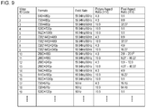
Fig. 9] Fig. 9 illustrates the correspondence (partially extracted) between "Video Format" and "Video Identification Code (Video ID Code). - [
Fig. 10] Fig. 10 illustrates the structure of Vendor Specific Data Block (VSDB) in the EDID structure. - [
Fig. 11] Fig. 11 illustrates a 3D format indicated by each value of "3D_structure". - [
Fig. 12] Fig. 12 illustrates examples of changes of the formats of stereoscopic image data in the flow of processing of processing of a broadcast station, a set top box, and a television receiver. - Hereinafter, modes for carrying out the invention (hereinafter referred to as an "embodiment") will be described. Meanwhile, the description will be given in the following order.
- 1. Embodiment
- 2. Modification
-
Fig. 1 illustrates an example of the configuration of a stereoscopicimage display system 10 according to an embodiment. The stereoscopicimage display system 10 includes abroadcast station 100, a set top box (STB) 200, and atelevision receiver 300. - The set
top box 200 and thetelevision receiver 300 are connected to each other through an HDMI (High Definition Multimedia Interface)cable 400. The settop box 200 is provided with anHDMI terminal 202. Thetelevision receiver 300 is provided with anHDMI terminal 302. One end of theHDMI cable 400 is connected to theHDMI terminal 202 of theset top box 200, and the other end of theHDMI cable 400 is connected to theHDMI terminal 302 of thetelevision receiver 300. - The
broadcast station 100 transmits bit stream data in such a manner as to be carried on a broadcast wave. The bit stream data contains stereoscopic image data for displaying a stereoscopic image, audio data corresponding to the stereoscopic image data, and the like. Examples of the transmission formats of the stereoscopic image data from the broadcast station include a "Frame Sequential" method, a "Top & Bottom" method, and a "Side By Side" method. - The set
top box 200 receives bit stream data (transport stream) that is transmitted in such a manner as to be carried on a broadcast wave from thebroadcast station 100. This bit stream data, as described above, contains stereoscopic image data, audio data, and the like. The settop box 200 includes a bitstream processing unit 201. The bitstream processing unit 201 extracts stereoscopic image data, audio data, and the like from the bit stream data. -
Fig. 2 illustrates an example of the configuration of the settop box 200. The settop box 200 includes the bitstream processing unit 201, anHDMI terminal 202, anantenna terminal 203, adigital tuner 204, a videosignal processing circuit 205, anHDMI transmission unit 206, and an audiosignal processing circuit 207. Furthermore, the settop box 200 includes aCPU 211, aflash ROM 212, aDRAM 213, an internal bus 214, a remotecontrol receiving unit 215, and aremote control transmitter 216. - The
CPU 211 controls the operation of each unit of the settop box 200. Theflash ROM 212 performs the storage of control software and the saving of data. TheDRAM 213 forms a work area for theCPU 211. TheCPU 211 develops the data and the software that are read from theflash ROM 212 onto theDRAM 213, so that the software is started up so as to control each unit of the settop box 200. - The remote
control receiving unit 215 receives a remote control signal (remote control code) transmitted from theremote control transmitter 216, and supplies the remote control signal to theCPU 211. TheCPU 211 controls each unit of the settop box 200 on the basis of the remote control code. TheCPU 211, theflash ROM 212, and theDRAM 213 are connected to the internal bus 214. - The
antenna terminal 203 is a terminal for inputting a television broadcast signal received by the receiving antenna (not shown). Thedigital tuner 204 processes the television broadcast signal input to theantenna terminal 203, and outputs predetermined bit stream data (transport stream) corresponding to the selection channel of the user. - The bit
stream processing unit 201, as described above, extracts stereoscopic image data, audio data, and the like from the bit stream data. The videosignal processing circuit 205 performs an image quality adjustment process, a format conversion process, and the like on the stereoscopic image data (received stereoscopic image data) output from the bitstream processing unit 201, and supplies the stereoscopic image data after being processed to theHDMI transmission unit 206. - In the following case, the video
signal processing circuit 205 supplies the format of the received stereoscopic image data in an as-is format to theHDMI transmission unit 206 without performing format conversion. That is, it is a case in which handling is possible by thetelevision receiver 300, and thetelevision receiver 300 has requested that the transmission thereof is performed without performing format conversion. Furthermore, in other cases, the videosignal processing circuit 205 converts the format of the received stereoscopic image data into, for example, a format that is set in advance by the user, and supplies the received stereoscopic image data to theHDMI transmission unit 206. - A case in which, for example, the format of the received stereoscopic image data is "720P T&B (Top & Bottom) of 1280 x 720" will be considered. In this case, under the following conditions, the video
signal processing circuit 205 supplies the received stereoscopic image data in an as-is format to theHDMI transmission unit 206. "These conditions" are that thetelevision receiver 300 can handle the format of "720P T&B of 1280 x 720" and moreover thetelevision receiver 300 has requested that transmission of the stereoscopic image data be performed without performing format conversion. - Furthermore, in this case, under the following conditions, the video
signal processing circuit 205 converts the received stereoscopic image data into, for example, a format "1080i T&B of 1280 x 540", and supplies the stereoscopic image data to the HDMI transmission unit 206 (seeFig. 12 ). These conditions are that thetelevision receiver 300 cannot handle the format of "720P T&B of 1280 x 720". Furthermore, in this case, under the following conditions, the videosignal processing circuit 205 converts the received stereoscopic image data into, for example, a format of "1080i T&B of 1280 x 540", and supplies it to the HDMI transmission unit 206 (seeFig. 12 ). These conditions are that even though thetelevision receiver 300 can handle the format of "720P T&B of 1280 x 720", thetelevision receiver 300 has not requested that transmission of the stereoscopic image data be performed without performing format conversion. - The above-described format conversion process in the video
signal processing circuit 205 is performed under the control of theCPU 211. TheCPU 211 obtains E-EDID (Enhanced Extended Display Identification Data) from thetelevision receiver 300, as will be described later. Then, theCPU 211 performs control on the basis of the format information of the stereoscopic image data that can be handled, which is contained in the E-EDID, and information (request information) indicating whether or not the transmission of the stereoscopic image data is performed without performing format conversion. - The flowchart of
Fig. 3 illustrates an example of the procedure of the control process of theCPU 211. TheCPU 211 starts processing in step ST1, and after that, proceeds to the process of step ST2. In step ST2, theCPU 211 determines whether or not thetelevision receiver 300 has requested that transmission of the stereoscopic image data be performed without performing format conversion on the basis of the request information. When thetelevision receiver 300 has requested that transmission of the stereoscopic image data be performed without performing format conversion, theCPU 211 proceeds to the process of step ST3. - In step ST3, the
CPU 211 determines whether or not the format of the received stereoscopic image data is a format that can be handled by thetelevision receiver 300 on the basis of the format information. When the format is a format that can be handled, theCPU 211 determines in step ST4 that the received stereoscopic image data is output to thetelevision receiver 300 in the as-is format. In this case, theCPU 211 controls the videosignal processing circuit 205 so that the received stereoscopic image data is supplied to theHDMI transmission unit 206 in the as-is format. After the process of step ST4, in step ST5, theCPU 211 ends the control process. - When the
television receiver 300 has not requested in step ST2 that the stereoscopic image data be transmitted without performing format conversion, theCPU 211 proceeds to the process of step ST6. Furthermore, in step ST3, when the format of the received stereoscopic image data is not a format that can be handled by thetelevision receiver 300, theCPU 211 proceeds to the process of step ST6. In step ST6, theCPU 211 determines that the format of the received stereoscopic image data is converted into a user set format, and that the stereoscopic image data is output to thetelevision receiver 300. In this case, theCPU 211 controls the videosignal processing circuit 205 so that the format of the received stereoscopic image data is converted into a user set format, and the stereoscopic image data is supplied to theHDMI transmission unit 206. After the process of step ST6, theCPU 211 ends the control process in step ST5. - Furthermore, the flowchart of
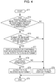
Fig. 4 illustrates another example of the procedure of the control process of theCPU 211. InFig. 4 , steps corresponding to those inFig. 3 are shown with the same reference numerals. When it is determined in step ST3 that the format of the received stereoscopic image data is a format that can be handled by thetelevision receiver 300, theCPU 211 proceeds to the process of step ST7. In step ST7, theCPU 211 performs display of a confirmation screen. This confirmation screen is used to make a user confirm that the received stereoscopic image data is output to thetelevision receiver 300 in the as-is format. This confirmation screen is displayed on thetelevision receiver 300. In this case, the videosignal processing circuit 205 is controlled so that image data on which a display signal for the confirmation screen has been superposed is transmitted to theHDMI transmission unit 206. - Next, the
CPU 211 proceeds to the process of step ST8. In step ST8, theCPU 211 determines whether or not the user has permitted that the received stereoscopic image data is output to thetelevision receiver 300 in the as-is format. When the user gives his/her permission, theCPU 211 proceeds to the process of step ST4, and determines that the received stereoscopic image data is output to thetelevision receiver 300 in the as-is format. On the other hand, when the user does not give his/her permission, in step ST6, theCPU 211 determines that the format of the received stereoscopic image data is converted into a user set format and outputs the received stereoscopic image data to thetelevision receiver 300. - The processing of the remaining steps of the flowchart of
Fig. 4 is the same as the processing of the corresponding steps in the flowchart ofFig. 3 . As described above, in the control process of the flowchart ofFig. 4 , under the following conditions, the videosignal processing circuit 205 is controlled so that the received stereoscopic image data is converted into a user set format and is transmitted. These conditions are that thetelevision receiver 300 has requested that transmission of the stereoscopic image data be performed without performing format conversion, and moreover the user does not give his/her permission even if the format of the received stereoscopic image data is a format that can be handled by thetelevision receiver 300. - The audio
signal processing circuit 207 performs a sound quality adjustment process and the like as necessary on the audio data output from the bitstream processing unit 201, and supplies the audio data after the process to theHDMI transmission unit 206. TheHDMI transmission unit 206 sends the stereoscopic image data and the audio data of the baseband from theHDMI terminal 202 in accordance with the communication in compliance with HDMI. TheHDMI transmission unit 206 is in a state of being capable of handing stereoscopic image data. In order to transmit the data through a TMDS channel of HDMI, theHDMI transmission unit 206 packs image and audio data, and outputs the data to theHDMI terminal 202. The details of theHDMI transmission unit 206 will be described later. - The operation of the set
top box 200 will be briefly described. A television broadcast signal input to theantenna terminal 203 is supplied to thedigital tuner 204. In thisdigital tuner 204, the television broadcast signal is processed, and predetermined bit stream data (transport stream) corresponding to the selection channel of the user is output. - The bit stream data output from the
digital tuner 204 is supplied to the bitstream processing unit 201. In this bitstream processing unit 201, stereoscopic image data, audio data, and the like, which are contained in the bit stream data, are extracted. The stereoscopic image data output from the bitstream processing unit 201 is supplied to the videosignal processing circuit 205. In the videosignal processing circuit 205, an image quality adjustment process, a format conversion process, and the like are performed on the stereoscopic image data (received stereoscopic image data) output from the bitstream processing unit 201. - The stereoscopic image data after being processed, which is output from the video
signal processing circuit 205, is supplied to theHDMI transmission unit 206. Furthermore, the audio data obtained in the bitstream processing unit 201, after a sound quality adjustment process and the like are performed thereon as necessary by the audiosignal processing circuit 207, is supplied to theHDMI transmission unit 206. In theHDMI transmission unit 206, the stereoscopic image data and the audio data are packed and sent to theHDMI cable 400 from theHDMI terminal 202. - Referring back to
Fig. 1 , thetelevision receiver 300 receives stereoscopic image data that is sent through theHDMI cable 400 from the settop box 200. Thetelevision receiver 300 includes a 3Dsignal processing unit 301. The 3Dsignal processing unit 301 performs a process (decoding process) corresponding to the transmission method on the stereoscopic image data so as to obtain left-eye image data and right-eye image data. -
Fig. 5 illustrates an example of the configuration of thetelevision receiver 300. Thetelevision receiver 300 includes the 3Dsignal processing unit 301, anHDMI terminal 302, anHDMI receiving unit 303, anantenna terminal 304, adigital tuner 305, and a bitstream processing unit 306. Furthermore, thetelevision receiver 300 includes a video/graphic processing circuit 307, apanel driving circuit 308, adisplay panel 309, an audiosignal processing circuit 310, anaudio amplification circuit 311, and aspeaker 312. Furthermore, thetelevision receiver 300 includes aCPU 321, aflash ROM 322, aDRAM 323, aninternal bus 324, a remotecontrol receiving unit 325, and aremote control transmitter 326. - The
CPU 321 controls the operation of each unit of thetelevision receiver 300. Theflash ROM 322 performs the storage of control software and the saving of data. TheDRAM 323 forms a work area for theCPU 321. TheCPU 321 develops software and data read from theflash ROM 322 onto theDRAM 323 so that the software is started up to control each unit of thetelevision receiver 300. - The remote
control receiving unit 325 receives a remote control signal (remote control code) transmitted from theremote control transmitter 326, and supplies the remote control signal to theCPU 321. TheCPU 321 controls each unit of thetelevision receiver 300 on the basis of the remote control code. TheCPU 321, theflash ROM 322, and theDRAM 323 are connected to theinternal bus 324. - The
antenna terminal 304 is a terminal through which a television broadcast signal received by a receiving antenna (not shown) is input. Thedigital tuner 305 processes the television broadcast signal input to theantenna terminal 304, and outputs predetermined bit stream data (transport stream) corresponding to the selection channel of the user. - The bit
stream processing unit 306 has a configuration identical to that of the bitstream processing unit 201 of the settop box 200 shown inFig. 2 . The bitstream processing unit 306 extracts stereoscopic image data, audio data, and the like from the bit stream data. TheHDMI receiving unit 303 receives the stereoscopic image data and the audio data, which are supplied to theHDMI terminal 302 through theHDMI cable 400 in accordance with communication in compliance with HDMI. TheHDMI receiving unit 303 is in a state of capable of handing stereoscopic image data. The details of theHDMI receiving unit 303 will be described later. - The 3D
signal processing unit 301 performs a decoding process on the stereoscopic image data that is received by theHDMI receiving unit 303 or obtained by the bitstream processing unit 306, and generates left-eye image data and right-eye image data. In this case, the 3Dsignal processing unit 301 performs a decoding process corresponding to the format of the stereoscopic image data on the stereoscopic image data. The video/graphic processing circuit 307 generates image data for displaying a stereoscopic image on the basis of the left-eye image data and the right-eye image data that are generated by the 3Dsignal processing unit 301. - Furthermore, the video/
graphic processing circuit 307 performs an image quality adjustment process on the image data as necessary. Furthermore, the video/graphic processing circuit 307 combines data of superimposition information, such as a menu and a program table, as necessary with the image data. Thepanel driving circuit 308 drives thedisplay panel 309 on the basis of the image data output from the video/graphic processing circuit 307. Thedisplay panel 309 is made up of, for example, an LCD (Liquid Crystal Display) or a PDP (Plasma Display Panel). - The audio
signal processing circuit 310 performs a necessary process, such as D/A conversion, on the audio data that is received by theHDMI receiving unit 303 or obtained by the bitstream processing unit 306. Theaudio amplification circuit 311 amplifies the audio signal output from the audiosignal processing circuit 310 and supplies the audio signal to thespeaker 312. - The operation of the
television receiver 300 shown inFig. 5 will be briefly described. In theHDMI receiving unit 303, the stereoscopic image data and the audio data that are transmitted from the settop box 200 that is connected to theHDMI terminal 302 through theHDMI cable 400 are received. The stereoscopic image data received by theHDMI receiving unit 303 is supplied to the 3Dsignal processing unit 301. Furthermore, the audio data received by theHDMI receiving unit 303 is supplied to the audiosignal processing circuit 310. - A television broadcast signal input to the
antenna terminal 304 is supplied to thedigital tuner 305. In thisdigital tuner 305, the television broadcast signal is processed, and predetermined bit stream data (transport stream) corresponding to the selection channel of the user is output. - The bit stream data output from the
digital tuner 305 is supplied to the bitstream processing unit 306. In the bitstream processing unit 306, stereoscopic image data, audio data, and the like are extracted from the bit stream data. The stereoscopic image data extracted by the bitstream processing unit 306 is supplied to the 3Dsignal processing unit 301. Furthermore, the audio data extracted by the bitstream processing unit 306 is supplied to the audiosignal processing circuit 310. - In the 3D
signal processing unit 301, a decoding process is performed on the stereoscopic image data received by theHDMI receiving unit 303 or extracted by the bitstream processing unit 306, and left-eye image data and right-eye image data are generated. The left-eye image data and the right-eye image data are supplied to the video/graphic processing circuit 307. In the video/graphic processing circuit 307, image data for displaying a stereoscopic image is generated on the basis of the left-eye image data and the right-eye image data, and an image quality adjustment process and a superimposition information data combining process are also performed as necessary. - The image data obtained by the video/
graphic processing circuit 307 is supplied to thepanel driving circuit 308. As a consequence, a stereoscopic image is displayed on thedisplay panel 309. For example, on thedisplay panel 309, a left-eye image using left-eye image data and a right-eye image using right-eye image data are alternately displayed in a time-division manner. A viewer, by wearing shutter glasses in which a left eye shutter and a right-eye shutter alternately open in synchronization with the display of thedisplay panel 309, can view only the left-eye image with the left eye and only the right-eye image with the right eye, and is thereby capable of perceiving a stereoscopic image. - Furthermore, in the audio
signal processing circuit 310, a necessary process, such as D/A conversion, is performed on the audio data that is received by theHDMI receiving unit 303 or extracted by the bitstream processing unit 306. This audio data is amplified by theaudio amplification circuit 311 and thereafter is supplied to thespeaker 312. As a consequence, audio corresponding to the display image of thedisplay panel 309 is output from thespeaker 312. -
Fig. 6 illustrates an example of the configuration of the HDMI transmission unit (HDMI source) 206 of the settop box 200 and the HDMI receiving unit (HDMI sink) 303 of thetelevision receiver 300 in the stereoscopicimage display system 10 ofFig. 1 . - In an effective image section (hereinafter will also be referred to as an active video section as appropriate), the
HDMI transmission unit 206 transmits a differential signal corresponding to non-compressed pixel data of an image for the amount of one screen to theHDMI receiving unit 303 in one direction through a plurality of channels. Here, the effective image section is a section in which the horizontal blanking period and the vertical blanking period are excluded from the section from one vertical synchronization signal up to the next vertical synchronization signal. Furthermore, in the horizontal blanking period or in the vertical blanking period, theHDMI transmission unit 206 transmits a differential signal corresponding to at least audio data and control data accompanying an image, other auxiliary data, and the like to theHDMI receiving unit 303 in one direction through a plurality of channels. - Examples of transmission channels of the HDMI system constituted by the
HDMI transmission unit 206 and theHDMI receiving unit 303 include the following transmission channels. That is, there are threeTMDS channels # 0 to #2 as transmission channels for serially transmitting pixel data and audio data in one direction in synchronization with a pixel clock from theHDMI transmission unit 206 to theHDMI receiving unit 303. Furthermore, there is a TMDS clock channel as a transmission channel for transmitting a pixel clock. - The
HDMI transmission unit 206 includes anHDMI transmitter 81. For example, thetransmitter 81 converts non-compressed pixel data of an image into corresponding differential signals, and serially transmits the differential signals to theHDMI receiving unit 303 in one direction through theHDMI cable 400 using threeTMDS channels # 0, #1, and #2, which are a plurality of channels. - Furthermore, the
transmitter 81 converts the audio data accompanying the non-compressed image, necessary control data, other auxiliary data, and the like into corresponding differential signals, and serially transmits the differential signals in one direction to theHDMI receiving unit 303 using threeTMDS channels # 0, #1, and #2. - In addition, the
transmitter 81 transmits a pixel clock synchronized with the pixel data that is transmitted using threeTMDS channels # 0, #1, and #2 by using the TMDS clock channel through theHDMI cable 400. Here, in one TMDS channel #i (i = 0, 1, 2), 10-bit pixel data is transmitted during one clock of the pixel clock. - In the active video section, the
HDMI receiving unit 303 receives the differential signal corresponding to the pixel data, which is transmitted in one direction from theHDMI transmission unit 206 by using a plurality of channels. Furthermore, in the horizontal blanking period or in the vertical blanking period, theHDMI receiving unit 303 receives the differential signals corresponding to the audio data and the control data, which are transmitted in one direction from theHDMI transmission unit 206 by using a plurality of channels. - That is, the
HDMI receiving unit 303 includes anHDMI receiver 82. TheHDMI receiver 82 receives the differential signals corresponding to the pixel data, and the differential signals corresponding to the audio data and the control data, which are transmitted in one direction from theHDMI transmission unit 206 by using theTMDS channels # 0, #1, and #2. In this case, the differential signals are is received in synchronization with the pixel clock transmitted from theHDMI transmission unit 206 through the TMDS clock channel. - Examples of the HDMI system include, in addition to the
TMDS channels # 0 to #2 and the TMDS clock channel described above, transmission channels called a DDC (Display Data Channel) 83 and aCEC line 84. TheDDC 83 is formed from
two signal lines (not shown) contained in theHDMI cable 400. TheDDC 83 is used for theHDMI transmission unit 206 to read E-EDID (Enhanced Extended Display Identification Data) from theHDMI receiving unit 303. - The
HDMI receiving unit 303 includes, in addition to theHDMI receiver 81, an EDID ROM (Read Only Memory) 85 in which E-EDID that is performance information regarding the performance (configuration/capability) of theHDMI receiving unit 303 is stored. TheHDMI transmission unit 206, in response to, for example, the request of the CPU 211 (seeFig. 2 ), reads E-EDID through theDDC 83 from theHDMI receiving unit 303 connected through theHDMI cable 400. - The
HDMI transmission unit 206 sends the read E-EDID to theCPU 211. TheCPU 211 stores this E-EDID in theflash ROM 212 or theDRAM 213. As described above, the E-EDID contains the format information regarding the stereoscopic image data, which can be handled by thetelevision receiver 300, and information (request information) indicating whether or not thetelevision receiver 300 has requested that transmission of the stereoscopic image data be performed without performing format conversion. - The
CEC line 84 is formed from one signal line (not shown) contained in theHDMI cable 400, and is used to perform both-way communication of data for control between theHDMI transmission unit 206 and theHDMI receiving unit 303. ThisCEC line 84 forms a control data line. - Furthermore, the
HDMI cable 400 includes a line (HPD line) 86 connected to a pin called an HPD (Hot Plug Detect). The source device can use therelevant line 86 so as to detect the connection of a sink device. Meanwhile, thisHPD line 86 can also be used as a HEAC-line forming a both-way communication path. Furthermore, theHDMI cable 400 includes a line (power-supply line) 87 that is used to supply power from the source device to the sink device. In addition, theHDMI cable 400 includes autility line 88. Thisutility line 88 is also used as a HEAC+ line forming a both-way communication path. - In the manner described above, in response to the request of the CPU 211 (see
Fig. 2 ), theHDMI transmission unit 206, for example, reads E-EDID through theDDC 83 from theHDMI receiving unit 303 connected through theHDMI cable 400. Then, on the basis of the E-EDID, theCPU 211 obtains the format information of the stereoscopic image data, which can be handled by thetelevision receiver 300 and information (request information) indicating whether or not it has been requested that transmission of the stereoscopic image data be performed without performing format conversion. -
Fig. 7 illustrates an EDID structure (Block 1 and thereafter, expansion portions for HDMI). This EDID structure, though its details are omitted, is defined in the EIA/CEA-861B standard. - In each "CEA Short Video Descriptor" of "Video Data Block", video formats that can be displayed by the television receiver (sink device) 300 are defined.
Fig. 8 illustrates the details of "CEA Short Video Descriptor". Displayable "Video Data" is specified in 7-bit "VIC: Video Identification Code".Fig. 9 illustrates the correspondence (partially extracted) between "Video Format" and "Video Identification Code (Video ID Code). For example, in the format of 1280 x 720P, "Video Identification Code = 4". - Furthermore,
Fig. 10 illustrates an example of the structure of an HDMI Vendor Specific Data Block (VSDB). In the zeroth block, the header indicating the data area of data "Vender Specific" indicated by "Vendor-Specific tag code (= 3)" is placed. Furthermore, in this zeroth block, the information indicating the length of the data "Vender Specific" represented by "Length (= N)" is placed. Furthermore, in the first block to the third block, the information indicating number "0x000C03" registered for HDMI (R) represented by "24-bit IEEE Registration Identifier (0x000C03) LSB first" is placed. - Furthermore, in the seventh bit of the thirteenth block, a flag indicating whether or not stereoscopic image data (3D image data) represented by "3D_present" can be handled is placed. Furthermore, in the fourth bit to the zeroth bit of the fourteenth block, the size information of the blocks, which indicates a 3D data structure that can be handled in addition to a mandatory 3D data structure, which is placed in the fifteenth block and thereafter, which is represented by "HDMI_3D_LEN", is placed.
- In a case where there is a 3D data structure (stereoscopic image data format) that can be handled in addition to a mandatory 3D data structure, E-EDID is registered in the following manner. First, "Video Identification Code" of this 3D data structure is registered in the n-th "CEA Short Video Descriptor". Furthermore, the number of the "CEA Short Video Descriptor", in which "Video Identification Code" is registered as described above, is registered in the L-th "2D_VIC_order_L" of HDMI VSDB. In addition, "3D_structure" of this 3D data structure is registered in the L-th "3D_structure_L".
- Specifically, in a case where handling of a 3D data structure (stereoscopic image data format) of 1280 x 720P T&B is possible in addition to the mandatory 3D data structure, the following registrations are performed in the E-EDID. First, since "1280 x 720P" is "Video Identification Code = 4" (see
Fig. 9 ), "4" is registered in the zeroth "CEAShort Video Descriptor 1". Then, "0000", which is the number of this "CEAShort Video Descriptor 1", is described in "2D_VIC_order_1" of HDMI VSDB. Furthermore, "3D_structure" of "T&B" is, for example, "0110", as shown inFig. 11 . As a consequence, "0110 is registered in 3D_structure_1". - Furthermore, in a predetermined reserved bit, for example, the zeroth bit of the thirteenth block in this example, a 1-bit flag represented by "3D_not_conv" is newly defined and arranged. This flag is information (request information) for requesting the set
top box 200 to transmit the received image data without performing format conversion. When "3D_not_conv = 0", this indicates that no request is made, and when "3D_not_conv = 1", a request is made. - Meanwhile, in the example of the structure of HDMI Vendor Specific Data Block (VSDB) shown in
Fig. 10 , a 1-bit flag "3D_not_conv" is placed in the zeroth bit of the thirteenth block. However, it is not necessarily necessary to be placed in this manner. the flag may be placed in any one of the sixth bit to the first bit of the thirteenth block, and furthermore, in a reserved bit position of another block. - As described above, in the stereoscopic
image display system 10 shown inFig. 1 , in the settop box 200, as a result of a predetermined condition being satisfied, received stereoscopic image data from a broadcast station is transmitted to thetelevision receiver 300 in the as-is format without performing format conversion. Here, the predetermined conditions are that the format of the received stereoscopic image data is a format that can be handled by thetelevision receiver 300, and that thetelevision receiver 300 has requested that transmission of the stereoscopic image data be performed in the as-is format. As a consequence, in the settop box 200, the received stereoscopic image data can be transmitted to thetelevision receiver 300 without performing unnecessary format conversion, and image quality deterioration due to format conversion can be prevented. - Furthermore, in the stereoscopic
image display system 10 shown inFig. 1 , in the settop box 200, the information for a format conversion process is obtained by reading anEDID ROM 85 provided in thetelevision receiver 300. This information is the format information regarding the stereoscopic image data that can be handled by thetelevision receiver 300 and information about whether or not thetelevision receiver 300 has requested that the transmission of the stereoscopic image data be performed without performing format conversion. As a consequence, it is possible to eliminate the time and effort for inputting information by the user, and the ease of use for the user can be improved. - Furthermore, in the stereoscopic
image display system 10 shown inFig. 1 , in the settop box 200, for example, when the above-mentioned predetermined conditions are satisfied and furthermore permission of the user is obtained, the received image data is transmitted to thetelevision receiver 300 without performing format conversion. In this case, even if the format of the received stereoscopic image data is a format that can be handled by thetelevision receiver 300, since the user does not give his/her permission, for example, the received stereoscopic image data is converted into a predetermined format and is transmitted. - Furthermore, in the stereoscopic
image display system 10 shown inFig. 1 , in the settop box 200, when the above-mentioned predetermined conditions are not satisfied, the received stereoscopic image data is converted into a preset format and is transmitted to thetelevision receiver 300. In this case, since the received stereoscopic image data is converted into a preset format and is transmitted, handling in thetelevision receiver 300 becomes possible. - Meanwhile, in the above-described embodiment, the set
top box 200 is configured to transmit, under the following conditions, the received stereoscopic image data to thetelevision receiver 300 in the as-is format without performing format conversion. These conditions are that the format of the received stereoscopic image data is a format that can be handled by thetelevision receiver 300 and that thetelevision receiver 300 has requested that the transmission thereof is performed in the as-is format. - However, when the format of the received stereoscopic image data is a format that can be handled by the
television receiver 300, it is also considered that the received stereoscopic image data is transmitted to thetelevision receiver 300 in the as-is format without performing format conversion. In this case, it is not necessary for thetelevision receiver 300 to place information about whether or not it has been requested that transmission of the stereoscopic image data be performed without performing format conversion in HDMI VSDB. - Furthermore, in the embodiment, the set
top box 200 is configured to receive stereoscopic image data from a broadcast signal from thebroadcast station 100. However, it is also considered that the settop box 200 receives stereoscopic image data from a streaming server through a network. - Furthermore, in the above-described embodiment, the set
top box 200 is configured to convert, under the following conditions, received stereoscopic image data into a preset format and transmit it to thetelevision receiver 300. This condition is that the format of the received stereoscopic image data is not a format that can be handled by thetelevision receiver 300 or that thetelevision receiver 300 has not requested that the transmission thereof is performed without performing format conversion. However, at this time, the settop box 200 is considered to be configured to convert received stereoscopic image data into a mandatory format and transmit it to thetelevision receiver 300. - Furthermore, in the above-described embodiment, the set
top box 200 is configured to directly transmit stereoscopic image data received by thedigital tuner 204 to thetelevision receiver 300. However, the settop box 200 may also be configured to prestore the stereoscopic image data received by thedigital tuner 204 in a storage (not shown), read stereoscopic image data from the storage, and transmit the stereoscopic image data to thetelevision receiver 300 at an predetermined timing. The predetermined timing is, for example, a timing of a reproduction operation by the user. - Furthermore, in the above-described embodiment, the set
top box 200 is configured to transmit received stereoscopic image data to thetelevision receiver 300. However, in place of thetelevision receiver 300, a configuration of transmitting received stereoscopic image data to a monitor device, a projector, or the like, is considered. Furthermore, in place of the settop box 200, a configuration, such as a recorder with a receiving function or a personal computer, is considered. - Furthermore, in the above-described embodiment, the set
top box 200 and thetelevision receiver 300 are connected to each other through theHDMI cable 400. However, of course, this invention can also be applied the same to a case where these are connected wirelessly. - This invention can be applied to a set top box or the like, which receives stereoscopic image data and transmits this stereoscopic image data to a television receiver by means of a digital interface, such as HDMI. Reference Signs List
-
- 310
- stereoscopic image display system
- 85
- EDID ROM
- 100
- broadcast station
- 200
- set top box
- 201
- bit stream processing unit
- 202
- HDMI terminal
- 203
- antenna terminal
- 204
- digital tuner
- 205
- video signal processing circuit
- 206
- HDMI transmission unit
- 207
- audio signal processing circuit
- 211
- CPU
- 212
- flash ROM
- 213
- DRAM
- 214
- internal bus
- 215
- remote control receiving unit
- 216
- remote control transmitter
- 300
- television receiver
- 301
- 3D signal processing unit
- 302
- HDMI terminal
- 303
- HDMI receiving unit
- 304
- antenna terminal
- 305
- digital tuner
- 306
- bit stream processing unit
- 307
- video/graphic processing circuit
- 308
- panel driving circuit
- 309
- display panel
- 310
- audio signal processing circuit
- 311
- audio amplification circuit
- 312
- speaker
- 321
- CPU
- 322
- flash ROM
- 323
- DRAM
- 324
- internal bus
- 325
- remote control receiving unit
- 326
- remote control transmitter
- 400
- HDMI cable
Claims (5)
- An image data transmission apparatus comprising:an image data receiving unit configured to receive stereoscopic image data for displaying a stereoscopic image; andan image data transmission unit (81) configured to transmit the stereoscopic image data received by the image data receiving unit to an external device (303) through a transmission path provided by transmission lines,wherein the image data transmission unit is operable to read, via a second data path provided by data lines separate to the transmission lines, format data and request information stored in a storage unit (85) provided in the external device, the format data indicating stereoscopic image data format which can be handled by the external device and the request information indicating whether the external device has requested that transmission of stereoscopic image data be performed without performing format conversion; andwherein the image data transmission unit is operable to transmit, when a format of the stereoscopic image data received by the image data receiving unit is a format that can be handled by the external device, and the external device has requested that transmission of the stereoscopic image data be performed without performing format conversion, the stereoscopic image data received by the image data receiving unit to the external device without performing format conversion, andwherein the image data transmission unit is operable to convert, when the format of the stereoscopic image data received by the image data receiving unit is not a format that can be handled by the external device or when the external device has not requested that transmission of the stereoscopic image data be performed without performing format conversation, the stereoscopic image data received by the image data receiving unit into a preset format and transmits the stereoscopic image data to the external device.
- The image data transmission apparatus according to Claim 1,
wherein the image data transmission unit is operable to transmit, when the format of the stereoscopic image data that is received by the image data receiving unit is a format that can be handled by the external device, and the external device has requested that transmission of the stereoscopic image data be performed without performing format conversation, the stereoscopic image data received by the image data receiving unit to the external device without performing format conversation when permission of a user is obtained. - The image data transmission apparatus according to Claim 1,
wherein the image data transmission unit is operable to transmit the stereo-scopic image data received by the image data receiving unit to the external device through the transmission path by using a differential signal. - An image data transmission method in which image data is transmitted by a transmission path provided by transmission lines, the method comprising:an image data receiving step of receiving stereoscopic image data for displaying a stereoscopic image; anda step of reading, via a second data path provided by data lines separate to the transmission lines, format data and request information stored in a storage unit provided in the external device, the format data indicating stereoscopic image data format which can be handled by the external device and the request information indicating whether the external device has requested that transmission of stereoscopic image data be performed without performing format conversation, andan image data transmission step of transmitting the stereoscopic image data received in the image data receiving step to an external device through a transmission path,wherein, in the image data transmission step, when a format of the stereoscopic image data received in the image data receiving step is a format that can be handled by the external device, and the external device has requested that transmission of the stereoscopic image data be performed without performing format conversion, the stereoscopic image data received in the image data receiving step is transmitted to the external device without performing format conversion, andwherein, in the image data transmission step, when the format of the stereoscopic image data received by the image data receiving step is not a format that can be handled by the external device or when the external device has not requested that transmission of the stereoscopic image data be performed without performing format conversation, the stereoscopic image data received in the image data receiving step is converted into a preset format and the stereoscopic image data is transmitted to the external device.
- An image data receiving apparatus comprising:an image data receiving unit configured to receive stereoscopic image data for displaying a stereoscopic image through a transmission path provided by transmission lines from an external device; anda storage unit configured to store at least format information regarding stereoscopic image data format that can be handled and information about whether or not a request for transmitting the stereoscopic image data without performing format conversion is made, these two types of information being capable of being read by the external device via a second data path provided by data lines separate to the transmission lines.
Priority Applications (1)
| Application Number | Priority Date | Filing Date | Title |
|---|---|---|---|
| EP16160938.3A EP3070956B1 (en) | 2010-03-25 | 2011-03-22 | Image data transmitting device, image data transmitting method, and image data receiving device |
Applications Claiming Priority (2)
| Application Number | Priority Date | Filing Date | Title |
|---|---|---|---|
| JP2010070571A JP5577789B2 (en) | 2010-03-25 | 2010-03-25 | Image data transmitting apparatus, image data transmitting method, and image data receiving apparatus |
| PCT/JP2011/056861 WO2011118592A1 (en) | 2010-03-25 | 2011-03-22 | Image data transmitting device, image data transmitting method, and image data receiving device |
Related Child Applications (2)
| Application Number | Title | Priority Date | Filing Date |
|---|---|---|---|
| EP16160938.3A Division EP3070956B1 (en) | 2010-03-25 | 2011-03-22 | Image data transmitting device, image data transmitting method, and image data receiving device |
| EP16160938.3A Division-Into EP3070956B1 (en) | 2010-03-25 | 2011-03-22 | Image data transmitting device, image data transmitting method, and image data receiving device |
Publications (3)
| Publication Number | Publication Date |
|---|---|
| EP2413611A1 EP2413611A1 (en) | 2012-02-01 |
| EP2413611A4 EP2413611A4 (en) | 2013-12-18 |
| EP2413611B1 true EP2413611B1 (en) | 2016-09-21 |
Family
ID=44673143
Family Applications (2)
| Application Number | Title | Priority Date | Filing Date |
|---|---|---|---|
| EP11759397.0A Not-in-force EP2413611B1 (en) | 2010-03-25 | 2011-03-22 | Image data transmitting device, image data transmitting method, and image data receiving device |
| EP16160938.3A Not-in-force EP3070956B1 (en) | 2010-03-25 | 2011-03-22 | Image data transmitting device, image data transmitting method, and image data receiving device |
Family Applications After (1)
| Application Number | Title | Priority Date | Filing Date |
|---|---|---|---|
| EP16160938.3A Not-in-force EP3070956B1 (en) | 2010-03-25 | 2011-03-22 | Image data transmitting device, image data transmitting method, and image data receiving device |
Country Status (9)
| Country | Link |
|---|---|
| US (1) | US9497438B2 (en) |
| EP (2) | EP2413611B1 (en) |
| JP (1) | JP5577789B2 (en) |
| KR (1) | KR20120139528A (en) |
| CN (1) | CN102474665A (en) |
| BR (1) | BRPI1105783A2 (en) |
| RU (1) | RU2011147132A (en) |
| TW (1) | TW201210318A (en) |
| WO (1) | WO2011118592A1 (en) |
Families Citing this family (5)
| Publication number | Priority date | Publication date | Assignee | Title |
|---|---|---|---|---|
| KR101890323B1 (en) * | 2011-11-23 | 2018-08-21 | 엘지전자 주식회사 | Image display apparatus, settop box and method for operating the same |
| EP2597876A1 (en) | 2011-11-24 | 2013-05-29 | Koninklijke Philips Electronics N.V. | Interlaced 3D video |
| CN103283221B (en) * | 2011-12-27 | 2016-03-16 | 松下知识产权经营株式会社 | Telecommunication cable |
| US9596449B2 (en) * | 2012-02-16 | 2017-03-14 | Sony Corporation | Transmitting apparatus, transmitting method, and receiving apparatus |
| JP7003079B2 (en) * | 2019-03-14 | 2022-01-20 | 株式会社東芝 | Electronics |
Family Cites Families (15)
| Publication number | Priority date | Publication date | Assignee | Title |
|---|---|---|---|---|
| JP2002095018A (en) * | 2000-09-12 | 2002-03-29 | Canon Inc | Image display controller, image display system and method for displaying image data |
| US7283566B2 (en) * | 2002-06-14 | 2007-10-16 | Silicon Image, Inc. | Method and circuit for generating time stamp data from an embedded-clock audio data stream and a video clock |
| US20060031889A1 (en) * | 2002-12-11 | 2006-02-09 | Bennett James D | Video processing system with simultaneous multiple outputs each with unique formats |
| ATE518343T1 (en) * | 2004-06-04 | 2011-08-15 | Qualcomm Inc | INTERFACE DEVICE AND METHOD FOR HIGH DATA RATES |
| JP2007180746A (en) * | 2005-12-27 | 2007-07-12 | Funai Electric Co Ltd | Disk reproducing device and its video data output method |
| US20070186015A1 (en) * | 2006-02-08 | 2007-08-09 | Taft Frederick D | Custom edid content generation system and method |
| JP4179387B2 (en) * | 2006-05-16 | 2008-11-12 | ソニー株式会社 | Transmission method, transmission system, transmission method, transmission device, reception method, and reception device |
| KR100801002B1 (en) * | 2006-06-05 | 2008-02-11 | 삼성전자주식회사 | Method for transferring/playing multimedia data on wireless network and wireless device thereof |
| US8934000B2 (en) * | 2008-01-29 | 2015-01-13 | Eastman Kodak Company | Switchable 2-D/3-D display system |
| JP5089493B2 (en) * | 2008-06-03 | 2012-12-05 | 三菱電機株式会社 | Digital video data transmitter, digital video data receiver, digital video data transmission system, digital video data transmission method, digital video data reception method, and digital video data transmission method |
| JP2010034704A (en) * | 2008-07-25 | 2010-02-12 | Sony Corp | Reproduction apparatus and reproduction method |
| JP5127633B2 (en) | 2008-08-25 | 2013-01-23 | 三菱電機株式会社 | Content playback apparatus and method |
| JP2010088092A (en) | 2008-09-02 | 2010-04-15 | Panasonic Corp | Three-dimensional video transmission system, video display device and video output device |
| EP2360935A4 (en) * | 2008-09-30 | 2012-06-20 | Panasonic Corp | Reproduction device, recording medium, and integrated circuit |
| JP5367814B2 (en) * | 2009-05-14 | 2013-12-11 | パナソニック株式会社 | Video data transmission method |
-
2010
- 2010-03-25 JP JP2010070571A patent/JP5577789B2/en active Active
-
2011
- 2011-03-09 TW TW100107924A patent/TW201210318A/en unknown
- 2011-03-22 WO PCT/JP2011/056861 patent/WO2011118592A1/en active Application Filing
- 2011-03-22 CN CN2011800026078A patent/CN102474665A/en active Pending
- 2011-03-22 RU RU2011147132/07A patent/RU2011147132A/en not_active Application Discontinuation
- 2011-03-22 EP EP11759397.0A patent/EP2413611B1/en not_active Not-in-force
- 2011-03-22 BR BRPI1105783A patent/BRPI1105783A2/en not_active IP Right Cessation
- 2011-03-22 KR KR1020117027268A patent/KR20120139528A/en not_active Application Discontinuation
- 2011-03-22 EP EP16160938.3A patent/EP3070956B1/en not_active Not-in-force
- 2011-03-22 US US13/320,967 patent/US9497438B2/en active Active
Also Published As
| Publication number | Publication date |
|---|---|
| US20120069158A1 (en) | 2012-03-22 |
| EP3070956A1 (en) | 2016-09-21 |
| RU2011147132A (en) | 2013-05-27 |
| EP3070956B1 (en) | 2019-03-06 |
| EP2413611A1 (en) | 2012-02-01 |
| JP2011205397A (en) | 2011-10-13 |
| JP5577789B2 (en) | 2014-08-27 |
| EP2413611A4 (en) | 2013-12-18 |
| BRPI1105783A2 (en) | 2016-05-03 |
| TW201210318A (en) | 2012-03-01 |
| KR20120139528A (en) | 2012-12-27 |
| CN102474665A (en) | 2012-05-23 |
| WO2011118592A1 (en) | 2011-09-29 |
| US9497438B2 (en) | 2016-11-15 |
Similar Documents
| Publication | Publication Date | Title |
|---|---|---|
| US10015468B2 (en) | Transmitting apparatus, stereo image data transmitting method, receiving apparatus, and stereo image data receiving method | |
| US8478914B2 (en) | Display apparatus, video signal transmission method for display apparatus, transmitting apparatus, and transmission method of video signal | |
| EP3145206B1 (en) | Communication apparatus, communication method, and computer program | |
| US9160959B2 (en) | Transmission device, transmission method, reception device, reception method, and transmission/reception system | |
| US20110141232A1 (en) | Image data transmitting apparatus, control method, and program | |
| US20080278567A1 (en) | Communication system, video signal transmission method, transmitter, transmitting method, receiver, and receiving method | |
| US20100275234A1 (en) | Display apparatus, data transmitting method in display apparatus, transmission apparatus, and data receiving method in transmission apparatus | |
| US10255875B2 (en) | Transmission device, transmission method, reception device, reception method, and transmission/reception system | |
| JP2010263382A (en) | Transmitter, transmission method of 3d image data, receiver, receiving method of 3d image data, relay device and relay method of 3d image data | |
| US20130100247A1 (en) | Image data transmission apparatus, control method for image data transmission apparatus, image data transmission method, and image data reception apparatus | |
| EP2413611B1 (en) | Image data transmitting device, image data transmitting method, and image data receiving device | |
| JP6307856B2 (en) | Transmitting device, wide color gamut image data transmitting method, receiving device, wide color gamut image data receiving method and program |
Legal Events
| Date | Code | Title | Description |
|---|---|---|---|
| PUAI | Public reference made under article 153(3) epc to a published international application that has entered the european phase |
Free format text: ORIGINAL CODE: 0009012 |
|
| 17P | Request for examination filed |
Effective date: 20111027 |
|
| AK | Designated contracting states |
Kind code of ref document: A1 Designated state(s): AL AT BE BG CH CY CZ DE DK EE ES FI FR GB GR HR HU IE IS IT LI LT LU LV MC MK MT NL NO PL PT RO RS SE SI SK SM TR |
|
| DAX | Request for extension of the european patent (deleted) | ||
| REG | Reference to a national code |
Ref country code: DE Ref legal event code: R079 Ref document number: 602011030581 Country of ref document: DE Free format text: PREVIOUS MAIN CLASS: H04N0013040000 Ipc: H04N0021440200 |
|
| A4 | Supplementary search report drawn up and despatched |
Effective date: 20131120 |
|
| RIC1 | Information provided on ipc code assigned before grant |
Ipc: H04N 7/173 20110101ALI20131114BHEP Ipc: H04N 13/04 20060101ALI20131114BHEP Ipc: H04N 21/4363 20110101ALI20131114BHEP Ipc: H04N 13/00 20060101ALI20131114BHEP Ipc: H04N 21/81 20110101ALI20131114BHEP Ipc: H04N 21/4402 20110101AFI20131114BHEP |
|
| 17Q | First examination report despatched |
Effective date: 20150206 |
|
| GRAP | Despatch of communication of intention to grant a patent |
Free format text: ORIGINAL CODE: EPIDOSNIGR1 |
|
| INTG | Intention to grant announced |
Effective date: 20160413 |
|
| GRAS | Grant fee paid |
Free format text: ORIGINAL CODE: EPIDOSNIGR3 |
|
| GRAA | (expected) grant |
Free format text: ORIGINAL CODE: 0009210 |
|
| AK | Designated contracting states |
Kind code of ref document: B1 Designated state(s): AL AT BE BG CH CY CZ DE DK EE ES FI FR GB GR HR HU IE IS IT LI LT LU LV MC MK MT NL NO PL PT RO RS SE SI SK SM TR |
|
| REG | Reference to a national code |
Ref country code: GB Ref legal event code: FG4D |
|
| REG | Reference to a national code |
Ref country code: CH Ref legal event code: EP |
|
| REG | Reference to a national code |
Ref country code: AT Ref legal event code: REF Ref document number: 831886 Country of ref document: AT Kind code of ref document: T Effective date: 20161015 |
|
| REG | Reference to a national code |
Ref country code: IE Ref legal event code: FG4D |
|
| REG | Reference to a national code |
Ref country code: DE Ref legal event code: R096 Ref document number: 602011030581 Country of ref document: DE |
|
| REG | Reference to a national code |
Ref country code: LT Ref legal event code: MG4D Ref country code: NL Ref legal event code: MP Effective date: 20160921 |
|
| PG25 | Lapsed in a contracting state [announced via postgrant information from national office to epo] |
Ref country code: FI Free format text: LAPSE BECAUSE OF FAILURE TO SUBMIT A TRANSLATION OF THE DESCRIPTION OR TO PAY THE FEE WITHIN THE PRESCRIBED TIME-LIMIT Effective date: 20160921 Ref country code: NO Free format text: LAPSE BECAUSE OF FAILURE TO SUBMIT A TRANSLATION OF THE DESCRIPTION OR TO PAY THE FEE WITHIN THE PRESCRIBED TIME-LIMIT Effective date: 20161221 Ref country code: LT Free format text: LAPSE BECAUSE OF FAILURE TO SUBMIT A TRANSLATION OF THE DESCRIPTION OR TO PAY THE FEE WITHIN THE PRESCRIBED TIME-LIMIT Effective date: 20160921 Ref country code: RS Free format text: LAPSE BECAUSE OF FAILURE TO SUBMIT A TRANSLATION OF THE DESCRIPTION OR TO PAY THE FEE WITHIN THE PRESCRIBED TIME-LIMIT Effective date: 20160921 |
|
| REG | Reference to a national code |
Ref country code: FR Ref legal event code: PLFP Year of fee payment: 7 |
|
| REG | Reference to a national code |
Ref country code: AT Ref legal event code: MK05 Ref document number: 831886 Country of ref document: AT Kind code of ref document: T Effective date: 20160921 |
|
| PG25 | Lapsed in a contracting state [announced via postgrant information from national office to epo] |
Ref country code: LV Free format text: LAPSE BECAUSE OF FAILURE TO SUBMIT A TRANSLATION OF THE DESCRIPTION OR TO PAY THE FEE WITHIN THE PRESCRIBED TIME-LIMIT Effective date: 20160921 Ref country code: NL Free format text: LAPSE BECAUSE OF FAILURE TO SUBMIT A TRANSLATION OF THE DESCRIPTION OR TO PAY THE FEE WITHIN THE PRESCRIBED TIME-LIMIT Effective date: 20160921 Ref country code: SE Free format text: LAPSE BECAUSE OF FAILURE TO SUBMIT A TRANSLATION OF THE DESCRIPTION OR TO PAY THE FEE WITHIN THE PRESCRIBED TIME-LIMIT Effective date: 20160921 Ref country code: GR Free format text: LAPSE BECAUSE OF FAILURE TO SUBMIT A TRANSLATION OF THE DESCRIPTION OR TO PAY THE FEE WITHIN THE PRESCRIBED TIME-LIMIT Effective date: 20161222 |
|
| PG25 | Lapsed in a contracting state [announced via postgrant information from national office to epo] |
Ref country code: RO Free format text: LAPSE BECAUSE OF FAILURE TO SUBMIT A TRANSLATION OF THE DESCRIPTION OR TO PAY THE FEE WITHIN THE PRESCRIBED TIME-LIMIT Effective date: 20160921 Ref country code: EE Free format text: LAPSE BECAUSE OF FAILURE TO SUBMIT A TRANSLATION OF THE DESCRIPTION OR TO PAY THE FEE WITHIN THE PRESCRIBED TIME-LIMIT Effective date: 20160921 |
|
| PG25 | Lapsed in a contracting state [announced via postgrant information from national office to epo] |
Ref country code: CZ Free format text: LAPSE BECAUSE OF FAILURE TO SUBMIT A TRANSLATION OF THE DESCRIPTION OR TO PAY THE FEE WITHIN THE PRESCRIBED TIME-LIMIT Effective date: 20160921 Ref country code: PT Free format text: LAPSE BECAUSE OF FAILURE TO SUBMIT A TRANSLATION OF THE DESCRIPTION OR TO PAY THE FEE WITHIN THE PRESCRIBED TIME-LIMIT Effective date: 20170123 Ref country code: ES Free format text: LAPSE BECAUSE OF FAILURE TO SUBMIT A TRANSLATION OF THE DESCRIPTION OR TO PAY THE FEE WITHIN THE PRESCRIBED TIME-LIMIT Effective date: 20160921 Ref country code: IS Free format text: LAPSE BECAUSE OF FAILURE TO SUBMIT A TRANSLATION OF THE DESCRIPTION OR TO PAY THE FEE WITHIN THE PRESCRIBED TIME-LIMIT Effective date: 20170121 Ref country code: BE Free format text: LAPSE BECAUSE OF FAILURE TO SUBMIT A TRANSLATION OF THE DESCRIPTION OR TO PAY THE FEE WITHIN THE PRESCRIBED TIME-LIMIT Effective date: 20160921 Ref country code: SK Free format text: LAPSE BECAUSE OF FAILURE TO SUBMIT A TRANSLATION OF THE DESCRIPTION OR TO PAY THE FEE WITHIN THE PRESCRIBED TIME-LIMIT Effective date: 20160921 Ref country code: SM Free format text: LAPSE BECAUSE OF FAILURE TO SUBMIT A TRANSLATION OF THE DESCRIPTION OR TO PAY THE FEE WITHIN THE PRESCRIBED TIME-LIMIT Effective date: 20160921 Ref country code: PL Free format text: LAPSE BECAUSE OF FAILURE TO SUBMIT A TRANSLATION OF THE DESCRIPTION OR TO PAY THE FEE WITHIN THE PRESCRIBED TIME-LIMIT Effective date: 20160921 Ref country code: BG Free format text: LAPSE BECAUSE OF FAILURE TO SUBMIT A TRANSLATION OF THE DESCRIPTION OR TO PAY THE FEE WITHIN THE PRESCRIBED TIME-LIMIT Effective date: 20161221 Ref country code: AT Free format text: LAPSE BECAUSE OF FAILURE TO SUBMIT A TRANSLATION OF THE DESCRIPTION OR TO PAY THE FEE WITHIN THE PRESCRIBED TIME-LIMIT Effective date: 20160921 |
|
| REG | Reference to a national code |
Ref country code: DE Ref legal event code: R097 Ref document number: 602011030581 Country of ref document: DE |
|
| PG25 | Lapsed in a contracting state [announced via postgrant information from national office to epo] |
Ref country code: IT Free format text: LAPSE BECAUSE OF FAILURE TO SUBMIT A TRANSLATION OF THE DESCRIPTION OR TO PAY THE FEE WITHIN THE PRESCRIBED TIME-LIMIT Effective date: 20160921 |
|
| PLBE | No opposition filed within time limit |
Free format text: ORIGINAL CODE: 0009261 |
|
| STAA | Information on the status of an ep patent application or granted ep patent |
Free format text: STATUS: NO OPPOSITION FILED WITHIN TIME LIMIT |
|
| PG25 | Lapsed in a contracting state [announced via postgrant information from national office to epo] |
Ref country code: DK Free format text: LAPSE BECAUSE OF FAILURE TO SUBMIT A TRANSLATION OF THE DESCRIPTION OR TO PAY THE FEE WITHIN THE PRESCRIBED TIME-LIMIT Effective date: 20160921 |
|
| 26N | No opposition filed |
Effective date: 20170622 |
|
| REG | Reference to a national code |
Ref country code: CH Ref legal event code: PL |
|
| PG25 | Lapsed in a contracting state [announced via postgrant information from national office to epo] |
Ref country code: SI Free format text: LAPSE BECAUSE OF FAILURE TO SUBMIT A TRANSLATION OF THE DESCRIPTION OR TO PAY THE FEE WITHIN THE PRESCRIBED TIME-LIMIT Effective date: 20160921 Ref country code: MC Free format text: LAPSE BECAUSE OF FAILURE TO SUBMIT A TRANSLATION OF THE DESCRIPTION OR TO PAY THE FEE WITHIN THE PRESCRIBED TIME-LIMIT Effective date: 20160921 |
|
| REG | Reference to a national code |
Ref country code: IE Ref legal event code: MM4A |
|
| PG25 | Lapsed in a contracting state [announced via postgrant information from national office to epo] |
Ref country code: LU Free format text: LAPSE BECAUSE OF NON-PAYMENT OF DUE FEES Effective date: 20170322 |
|
| REG | Reference to a national code |
Ref country code: FR Ref legal event code: PLFP Year of fee payment: 8 |
|
| PG25 | Lapsed in a contracting state [announced via postgrant information from national office to epo] |
Ref country code: LI Free format text: LAPSE BECAUSE OF NON-PAYMENT OF DUE FEES Effective date: 20170331 Ref country code: CH Free format text: LAPSE BECAUSE OF NON-PAYMENT OF DUE FEES Effective date: 20170331 Ref country code: IE Free format text: LAPSE BECAUSE OF NON-PAYMENT OF DUE FEES Effective date: 20170322 |
|
| PG25 | Lapsed in a contracting state [announced via postgrant information from national office to epo] |
Ref country code: MT Free format text: LAPSE BECAUSE OF NON-PAYMENT OF DUE FEES Effective date: 20170322 |
|
| PG25 | Lapsed in a contracting state [announced via postgrant information from national office to epo] |
Ref country code: AL Free format text: LAPSE BECAUSE OF FAILURE TO SUBMIT A TRANSLATION OF THE DESCRIPTION OR TO PAY THE FEE WITHIN THE PRESCRIBED TIME-LIMIT Effective date: 20160921 |
|
| PG25 | Lapsed in a contracting state [announced via postgrant information from national office to epo] |
Ref country code: HU Free format text: LAPSE BECAUSE OF FAILURE TO SUBMIT A TRANSLATION OF THE DESCRIPTION OR TO PAY THE FEE WITHIN THE PRESCRIBED TIME-LIMIT; INVALID AB INITIO Effective date: 20110322 |
|
| PG25 | Lapsed in a contracting state [announced via postgrant information from national office to epo] |
Ref country code: CY Free format text: LAPSE BECAUSE OF NON-PAYMENT OF DUE FEES Effective date: 20160921 |
|
| PG25 | Lapsed in a contracting state [announced via postgrant information from national office to epo] |
Ref country code: MK Free format text: LAPSE BECAUSE OF FAILURE TO SUBMIT A TRANSLATION OF THE DESCRIPTION OR TO PAY THE FEE WITHIN THE PRESCRIBED TIME-LIMIT Effective date: 20160921 |
|
| PG25 | Lapsed in a contracting state [announced via postgrant information from national office to epo] |
Ref country code: TR Free format text: LAPSE BECAUSE OF FAILURE TO SUBMIT A TRANSLATION OF THE DESCRIPTION OR TO PAY THE FEE WITHIN THE PRESCRIBED TIME-LIMIT Effective date: 20160921 |
|
| PG25 | Lapsed in a contracting state [announced via postgrant information from national office to epo] |
Ref country code: HR Free format text: LAPSE BECAUSE OF FAILURE TO SUBMIT A TRANSLATION OF THE DESCRIPTION OR TO PAY THE FEE WITHIN THE PRESCRIBED TIME-LIMIT Effective date: 20160921 |
|
| PGFP | Annual fee paid to national office [announced via postgrant information from national office to epo] |
Ref country code: GB Payment date: 20220322 Year of fee payment: 12 Ref country code: DE Payment date: 20220329 Year of fee payment: 12 |
|
| PGFP | Annual fee paid to national office [announced via postgrant information from national office to epo] |
Ref country code: FR Payment date: 20220325 Year of fee payment: 12 |
|
| REG | Reference to a national code |
Ref country code: DE Ref legal event code: R119 Ref document number: 602011030581 Country of ref document: DE |
|
| GBPC | Gb: european patent ceased through non-payment of renewal fee |
Effective date: 20230322 |
|
| PG25 | Lapsed in a contracting state [announced via postgrant information from national office to epo] |
Ref country code: GB Free format text: LAPSE BECAUSE OF NON-PAYMENT OF DUE FEES Effective date: 20230322 |
|
| PG25 | Lapsed in a contracting state [announced via postgrant information from national office to epo] |
Ref country code: GB Free format text: LAPSE BECAUSE OF NON-PAYMENT OF DUE FEES Effective date: 20230322 Ref country code: FR Free format text: LAPSE BECAUSE OF NON-PAYMENT OF DUE FEES Effective date: 20230331 Ref country code: DE Free format text: LAPSE BECAUSE OF NON-PAYMENT OF DUE FEES Effective date: 20231003 |