EP2413517A1 - Wireless communication system, base station, relay station, and terminal - Google Patents

Wireless communication system, base station, relay station, and terminal Download PDF

Info

Publication number
EP2413517A1
EP2413517A1 EP10755900A EP10755900A EP2413517A1 EP 2413517 A1 EP2413517 A1 EP 2413517A1 EP 10755900 A EP10755900 A EP 10755900A EP 10755900 A EP10755900 A EP 10755900A EP 2413517 A1 EP2413517 A1 EP 2413517A1
Authority
EP
European Patent Office
Prior art keywords
base station
signal
relay station
terminals
transmitted
Prior art date
Legal status (The legal status is an assumption and is not a legal conclusion. Google has not performed a legal analysis and makes no representation as to the accuracy of the status listed.)
Withdrawn
Application number
EP10755900A
Other languages
German (de)
French (fr)
Inventor
Shimpei To
Dirk Slock
Current Assignee (The listed assignees may be inaccurate. Google has not performed a legal analysis and makes no representation or warranty as to the accuracy of the list.)
Sharp Corp
Original Assignee
Sharp Corp
Priority date (The priority date is an assumption and is not a legal conclusion. Google has not performed a legal analysis and makes no representation as to the accuracy of the date listed.)
Filing date
Publication date
Application filed by Sharp Corp filed Critical Sharp Corp
Publication of EP2413517A1 publication Critical patent/EP2413517A1/en
Withdrawn legal-status Critical Current

Links

Images

Classifications

    • HELECTRICITY
    • H04ELECTRIC COMMUNICATION TECHNIQUE
    • H04BTRANSMISSION
    • H04B7/00Radio transmission systems, i.e. using radiation field
    • H04B7/02Diversity systems; Multi-antenna system, i.e. transmission or reception using multiple antennas
    • H04B7/022Site diversity; Macro-diversity
    • H04B7/024Co-operative use of antennas of several sites, e.g. in co-ordinated multipoint or co-operative multiple-input multiple-output [MIMO] systems
    • HELECTRICITY
    • H04ELECTRIC COMMUNICATION TECHNIQUE
    • H04BTRANSMISSION
    • H04B7/00Radio transmission systems, i.e. using radiation field
    • H04B7/14Relay systems
    • H04B7/15Active relay systems
    • H04B7/155Ground-based stations
    • H04B7/15528Control of operation parameters of a relay station to exploit the physical medium
    • HELECTRICITY
    • H04ELECTRIC COMMUNICATION TECHNIQUE
    • H04BTRANSMISSION
    • H04B7/00Radio transmission systems, i.e. using radiation field
    • H04B7/24Radio transmission systems, i.e. using radiation field for communication between two or more posts
    • H04B7/26Radio transmission systems, i.e. using radiation field for communication between two or more posts at least one of which is mobile
    • H04B7/2603Arrangements for wireless physical layer control
    • H04B7/2606Arrangements for base station coverage control, e.g. by using relays in tunnels
    • HELECTRICITY
    • H04ELECTRIC COMMUNICATION TECHNIQUE
    • H04LTRANSMISSION OF DIGITAL INFORMATION, e.g. TELEGRAPHIC COMMUNICATION
    • H04L25/00Baseband systems
    • H04L25/02Details ; arrangements for supplying electrical power along data transmission lines
    • H04L25/03Shaping networks in transmitter or receiver, e.g. adaptive shaping networks
    • H04L25/03891Spatial equalizers
    • H04L25/03949Spatial equalizers equalizer selection or adaptation based on feedback
    • HELECTRICITY
    • H04ELECTRIC COMMUNICATION TECHNIQUE
    • H04WWIRELESS COMMUNICATION NETWORKS
    • H04W84/00Network topologies
    • H04W84/02Hierarchically pre-organised networks, e.g. paging networks, cellular networks, WLAN [Wireless Local Area Network] or WLL [Wireless Local Loop]
    • H04W84/04Large scale networks; Deep hierarchical networks
    • H04W84/042Public Land Mobile systems, e.g. cellular systems
    • H04W84/047Public Land Mobile systems, e.g. cellular systems using dedicated repeater stations

Definitions

  • the present invention relates to a radio communication system and the like in which a base station and terminals perform bidirectional communication using the same frequency, via a relay station including plural transmitting and receiving antennas.
  • Examples of the relay stations may include one that merely amplifies the received signal and transmits the amplified signal (Amplify-and Forward: AF type), one that once demodulates and decodes the received signal and re-demodulates and transmits the signal if the signal is free from error (Decode-and-Forward: DF type), and others.
  • AF type amplifies the received signal and transmits the amplified signal
  • DF type decode-and-Forward
  • FIG. 11 shows an example of a radio communication system including such a relay station.
  • a base station 90 and a terminal 94 are connected via a relay station 92.
  • two frames are required to transmit the signal corresponding to one frame when the signal is relayed via relay station 92.
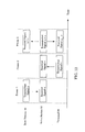
  • base station 90 transmits a signal to relay station 92 first and then the terminal transmits a signal to the relay station in the next frame, as shown in FIG. 12 .
  • the channel variation affecting each signal is omitted.
  • Relay station 92 combines the signals received in the different frames and broadcasts the combined signal in the third frame to base station 90 and terminal 94.
  • base station 90 and terminal 94 each receive the mixture of the two signals. So it is usually impossible to reproduce the original data.
  • base station 90 and terminal 94 grasp respective own transmitted signals, it is possible to detect the signal transmitted from the opposite side by subtracting the own transmitted signal from the received signal. As a result, it is possible to realize bidirectional communication via relay station 92, which usually requires four frames, by three frames, hence improves efficiency of frequency use.
  • FIG. 12 shows a configuration in which base station 90 and terminal 94 transmit to relay station 92 using different frames
  • base station 90 and terminal 94 perform transmission to relay station 92 at the same time. It is possible in this case to realize bidirectional communication via relay station 92 by two frames.
  • non-patent document 1 discusseed in non-patent document 1 is a case where the base station, relay station and terminal each have two antennas so that two streams of data (different data from each antenna) are transmitted from the base station and terminal.
  • non-patent document 1 discloses a configuration ( FIG. 13 ) in which when the relay station transmits a signal toward the base station and terminal, the signal is multiplied with a transmission weight, and the base station and terminal that receive this signal multiplies a reception weight on the signal after subtraction of the known interference (the own transmitted signal).
  • the base station and terminal each grasp two transmitted signals of their own (u 1 and u 2 for the base station and v 1 and v 2 for the terminal) so as to be able to subtract signals obtained by multiplying these signals by a channel variation or the like, from the received signals.
  • the signal obtained after subtraction of theself-interference (the known interference transmitted by itself) from the received signal is the sum of the two desired signals (v 1 and v 2 for the base station and u 1 and u 2 for the terminal) and noise, hence can be processed in the same manner as in normal MIMO (here, signal separation by multiplying a reception weight. Multiplication of the transmission and reception weights as this makes it possible to perform signal detection at the base station and terminal with a favorable performance, hence realize efficient bidirectional communication.
  • Non-patent document 2 demonstrates a technique for applying Two-way relaying (Bi-directional relaying) to multi-user MIMO (Multi-User-MIMO: MU-MIMO) communication in which a base station performs communication with plural terminals at the same time. Discussed in this non-patent document 2 is bidirectional communication using three units of time resources (frames) when the base station and relay station each have two antennas while two terminals each having one antenna exist ( FIG. 14 ).
  • frames time resources
  • the signal addressed from terminal A to terminal A is transmitted to the relay station, the signal addressed from terminal A to the base station is transmitted to the relay station in the first frame.
  • the signal transmitted from terminal A to the relay station is also received and demodulated at terminal B so that this demodulated signal will be used afterwards as the known interference signal.
  • the signal addressed from the base station to terminal B is transmitted to the relay station.
  • the signal addressed from terminal B to the base station is transmitted to the relay station.
  • the signal transmitted from terminal B to the relay station is also received and demodulated at terminal A so that this demodulated signal will be used afterwards as the known interference signal.
  • the relay station demodulates, decodes and modulates once again the signals received from the base station and the two terminals and combines them into a signal, which is broadcasted to the base station and two terminals.
  • the base station and two terminals having received this signal need to subtract signals forming interference in order to detect respective necessary signals. Since the base station grasps its own signals transmitted to the two terminals, it is possible to perform this subtraction to thereby extract the desired signal.
  • each terminal In performing MU-MIMO communication, each terminal usually grasps its own transmitted signal only, so that the terminal cannot subtract interference correctly, resulting in difficulty in realizing bidirectional communication.
  • the signal transmitted from one terminal is intentionally received and demodulated by the other, whereby it is possible for each terminal to grasp the signal transmitted from the other as the known interference and use it for subtraction.
  • Non-patent Document 1 N. Lee et al, "Linear Precoder and Decoder Design for Two-Way AF MIMO Relaying System, "VTC Spring 2008, May 2008 .
  • Non-patent Document 2 L. Weng et al, "MU-MIMO Relaying System with Self-interference Cancellation” WCNC 2007, Mar. 2007 .
  • the own transmitted signal, the signal transmitted by the other terminal and the signal transmitted to the other terminal by the base station are combined as interference with the desired signal.
  • each terminal knows its own transmitted signal only, so that it is impossible to appropriately subtract the inference (the signal transmitted by the other terminal and the signal transmitted to the other terminal by the base station), hence it is impossible to realize bidirectional communication using the transmission and reception weights as shown in non-patent document 1.
  • non-patent document 2 use of the technique shown in non-patent document 2 enables each terminal to grasp the interference signal to be subtracted (the signal transmitted by the other terminal) under MU-MIMO environment, but the terminal needs to perform a process of receiving and demodulating the signal that is transmitted from the other terminal to the relay station during the signal is being transmitted, hence it is difficult to realize when the terminals are located distant from each other. Further, this process is not preferable in view of power consumption at the terminal and from a privacy viewpoint for the transmitted data of the terminals. Moreover, the technique described in non-patent document 2 needs three units of time resources, so that it is desired to realize a highly efficient system for which the required resources are further cut down.
  • the object of the present invention is to provide a communication system and the like, which realize MU-MIMO bidirectional communication between a base station having plural antennas and plural terminals efficiently with a lower amount of resources when the communication is performed via a relay station.
  • the radio communication system is a radio communication system performing bidirectional communication between a base station including a plurality of transmitting and receiving antennas and a plurality of terminals using a same frequency via a relay station having a plurality of transmitting and receiving antennas, and is characterized in that the base station and plural terminals transmit signals to the relay station simultaneously in a first time frame, the relay station includes: a receiving means for receiving the signals transmitted in the first time frame as received signals; and, a transmitting means for generating a transmitted signal by multiplying the received signals by a relay station transmission weight W RS and transmitting the transmitted signal to the base station and plural terminals in a second time frame.
  • the radio communication system of the present embodiment is characterized in that the relay station transmission weight W RS is generated at least based on a channel between the relay station and terminals.
  • the radio communication system of the present embodiment is characterized in that the signal transmitted from the base station in the first time frame is a signal that is produced by multiplying a modulated signal by a base station transmission weight W TX .
  • the radio communication system of the present embodiment is characterized in that the base station transmission weight W TX is generated at least based on a channel between the base station and the relay station, or the channel between the relay station and terminals.
  • the radio communication system of the present embodiment is characterized in that the relay station transmission weight W RS and the base station transmission weight W TX are generated so as to have the transmitted streams from the base station all separated and received by individual terminals.
  • the radio communication system of the present embodiment is characterized in that each terminal having received the signal transmitted from the relay station in the second time frame, generates an interference signal based on the signal that the terminal transmitted in the first time frame and subtracts the generated interference signal from the received signal to detect the signal transmitted from the base station in the first frame.
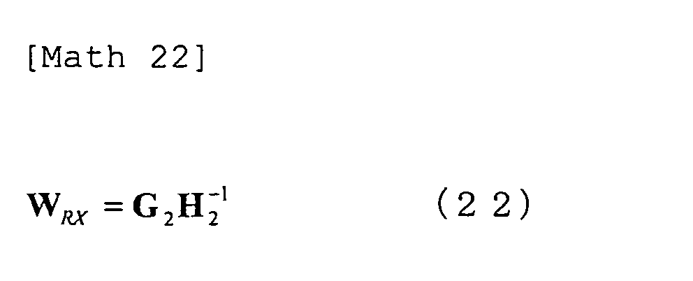
  • the radio communication system of the present embodiment is characterized in that the base station having received the signal transmitted from the relay station in the second time frame, generates an interference signal based on the signal that the base station transmits in the first time frame and subtracts the generated interference signal from the received signal and multiplies the signal after subtraction of the interference signal by a reception weight W RX to detect the signal transmitted from the terminal.
  • the radio communication system of the present embodiment is characterized in that the reception weight W RX is generated at least based on the channel between the base station and the relay station, or the channel between the relay station and the terminals.
  • the radio communication system of the present embodiment is characterized in that the relay station transmission weight W RS , the base station transmission weight W TX and the reception weight W RX are represented by equations (3), (5), (6), (8) and (9), where H is the channel matrix between the base station and the relay station, G is the channel matrix between the relay station and the plural terminals, P BS is the total transmission power of the base station, P RS is the total transmission power of the relay station, P MS is the sum of transmission powers of the terminals, the covariance matrix of the transmitted signal from base station before multiplication of the first transmission weight W TX is the unit matrix, M is the total number of antennas of the terminals, the square of ⁇ RS is the noise power at the relay station.
  • the radio communication system of the present embodiment is characterized in that the relay station transmission weight W RS , the base station transmission weight W TX and the reception weight W RX are represented by equations (23) to (29), where H is the channel matrix between the base station and the relay station, G is the channel matrix between the relay station and the plural terminals, P BS is the total transmission power of the base station, P RS is the total transmission power of the relay station, P MS is the sum of transmission powers of the terminals, Q u is the covariance matrix of the transmitted signal from the base station before multiplication of the base station transmission weight W TX , Q v is the covariance matrix of the transmitted signal of base station, M is the total number of antennas of the terminals, the square of ⁇ BS is the noise power at the base station, the square of ⁇ RS is the noise power at the relay station and, the square of ⁇ MS is the noise power of the terminals.
  • H is the channel matrix between the base station and the relay station
  • G is the channel matrix between the relay station and
  • the radio communication system of the present embodiment is characterized in that all the plural terminals have the same number of antennas.
  • the radio communication system of the present embodiment is characterized in that the plural terminals have a plurality of antennas.
  • the radio communication base station of the present invention is a base station having a plurality of transmitting and receiving antennas and performing bidirectional communication with a plurality of terminals using the same frequency via a relay station having a plurality of transmitting and receiving antennas, and includes: a transmitting means for transmitting a signal addressed to the plural terminals toward the relay station in a first time frame; and a receiving means for receiving the signal transmitted from the relay station in a second time frame.
  • the base station of the present invention is characterized in that the transmitting means transmits a signal that is produced by multiplying a modulated signal by a base station transmission weight W TX .
  • the base station of the present invention is characterized in that the base station transmission weight W TX is generated at least based on a channel between the base station and the relay station, or a channel between the relay station and the terminals.
  • the base station of the present invention is characterized in that the base station transmission weight W TX is generated so that the transmitted streams from the base station are all separated and received by individual terminals.
  • the base station of the present invention further includes: an interference signal generating means for generating an interference signal based on the signal that the base station itself transmits in the first time frame; and, an interference subtracting means for subtracting the generated interference signal from the signal received by the receiving means in the second time frame.
  • the base station of the present invention further includes: a reception weight multiplying means for multiplying the signal after subtraction of the interference signal by the interference subtracting means by a reception weight W RX ; and, a means for detecting the transmitted signal from the terminals after multiplication of the reception weight W RX .
  • the base station of the present invention is characterized in that the reception weight W RX is generated at least based on the channel between the base station and the relay station, or the channel between the relay station and the terminals.
  • the relay station of the present invention is a relay station relaying bidirectional communication between a base station having a plurality of transmitting and receiving antennas and a plurality of terminals using a same frequency, and includes: a receiving means for receiving the signals transmitted from the base station and the terminals in the first time frame as received signals; and, a transmitting means that transmitting a signal generated by multiplying the received signals in the first time frame by a relay station transmission weight W RS as the transmitted signals in a second time frame.
  • the relay station is characterized in that the relay station transmission weight W RS is generated at least based on the channel between the relay station and the terminals.
  • the relay station is characterized in that the relay station transmission weight W RS is generated in such a manner that the transmitted streams from the base station are all separated and received by individual terminals.
  • the terminal of the present invention is a terminal performing bidirectional communication with a base station having a plurality of transmitting and receiving antennas, via a relay station having a plurality of transmitting and receiving antennas using a same frequency as that of the base station and other terminals, and includes: a transmitting means for transmitting a signal addressed to the base station toward the relay station in a first time frame; and a receiving means for receiving the signal transmitted from the relay station in a second time frame.
  • the terminal of the present invention further includes: an interference signal generating means for generating an interference signal based on the signal that the terminal itself transmits in the first time frame; and an interference subtracting means for subtracting the generated interference signal from the received signal in the second time frame.
  • Use of the present invention makes it possible to realize MU-MIMO bidirectional communication between a base station having plural antennas and terminals, efficiently with a lower amount of resources (the number of frames: 2) when the communication is performed via a relay station. Specifically, it is possible to perform such control that each terminal can avoid receiving the signal involving unknown interference, by multiplying the transmitted signals by associated weights suitable for bidirectional communication under MU-MIMO environment. This weight multiplying control enables each terminal to receive the combined signal consisting of the desired signal and the known interference only, so that it is possible to efficiently detect the desired signal by subtracting the known interference. Further, also on the base station side, it is possible to subtract the known interference signal and obtain good reception performance by multiplying a reception weight.
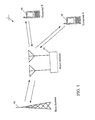
  • FIG. 1 is a diagram for illustrating the outline of a radio communication system 1.
  • terminals 30 terminal A and terminal B are connected to a base station 10 via a relay station 20.
  • the present invention relates to a method of realizing MU-MIMO bidirectional communication between a base station having a plurality of antennas and plural terminals by way of a relay station, in an efficient manner with a lower amount of resources.
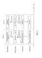
  • base station 10 and terminals 30 each transmit a signal to relay station 20 in the first time frame. Then, in the second time frame, relay station 20 broadcasts a signal to base station 10 and two terminals 30.
  • each of base station 10 and relay station 20 multiply the signal to be transmitted by a corresponding weight (W TX , W RS ) suitable for bidirectional communication under the MU-MIMO environment so as to perform control such that each terminal can avoid receiving any signal mixed with unknown interference.
  • W TX , W RS weight suitable for bidirectional communication under the MU-MIMO environment
  • u 1 is obtained in terminal A by interference subtraction while u 2 is obtained in terminal B by interference subtraction.
  • u 2 is obtained in terminal B by interference subtraction.
  • the first embodiment shows a case of MU-MIMO Two-way relaying where use is made of transmission and reception weights that make compensation so as to restore the received signal to its original state (to the signal corresponding to the transmitted signal) based on the concept of ZF (Zero Forcing).
  • base station 10 and relay station 20 each have two antennas while two terminals 30 each have one antenna.
  • the matrix that represents the channel variation affecting the signal that is being transmitted from base station 10 to relay station 20 is assumed as H, and the reverse (from relay station 20 to base station 10) is assumed as H T , the transpose of H.
  • the matrix that represents the channel variation affecting the signal that is being transmitted from terminals 30 (Terminal A and terminal B) to relay station 20 is assumed as G
  • the reverse (from relay station 20 to terminals 30) is assumed as G T , the transpose of G.
  • the channel variation affecting the signal that is being transmitted from antenna 1 of base station 10 to antenna 1 of relay station 20 is h 11
  • the channel variation from antenna 1 of base station 10 to antenna 2 of relay station 20 is h 21
  • the channel variation from antenna 2 of base station 10 to antenna 1 of relay station 20 is h 12
  • the channel variation from antenna 2 of base station 10 to antenna 2 of relay station 20 is h 22 .
  • the channel variation affecting the signal that is being transmitted from the antenna of terminal A to antenna 1 of relay station 20 is g 11
  • the channel variation from the antenna of terminal A to antenna 2 of relay station 20 is g 12
  • the channel variation from the antenna of terminal B to antenna 1 of relay station 20 is g 12
  • the channel variation from the antenna of terminal B to antenna 2 of relay station 20 is g 22 .
  • These channel variations can be given as the following expression, and base station 10 and relay station 20 are assumed to grasp these matrixes beforehand.
  • Math 1 H h 11 h 12 h 21 h 22
  • Math 2 G g 11 g 12 g 21 g 22
  • is a coefficient that normalizes the transmission power of the base station and is represented by the following equation.
  • Math 4 ⁇ / tr H - 1 ⁇ G ⁇ Q u ⁇ H - 1 ⁇ G H P BS
  • P BS represents the total transmission power of the base station
  • Q u the covariance matrix of the signal (before multiplication of W TX ) transmitted from the base station
  • tr(X) represents the trace (the sum of the diagonal components) of matrix X.
  • M represents the number of antennas (the number of terminals). In this case, M is "2".
  • I is the unit matrix.
  • is a coefficient that normalizes the transmission power of the relay station and is represented by the following expression.
  • P RS represents the total transmission power of the relay station
  • Q v the covariance matrix of the signal transmitted from the two terminals and the square of ⁇ RS the power of noise at the relay station.
  • G* represents the complex conjugate matrix of matrix G.
  • the received signals at base station 10 and two terminals 30 when the transmission and reception weights given by the above Eqs. (3) to (9) are used.
  • the transmission signal addressed from base station 10 to terminal A is u 1
  • the transmission signal addressed from the base station to terminal B is u 2
  • the transmission signal addressed to terminal A is v 1
  • the transmission signal addressed to terminal B is v 2 .
  • the noise component is omitted.
  • terminal A receives the combined signal of the desired signal u 1 and the known interference signal v 1 that was transmitted by itself without mixture of an unknown interference signal. Accordingly, it is possible to extract the desired signal u 1 by subtracting the known interference signal v 1 multiplied by transmission power normalizing coefficient ⁇ , from the received signal.
  • terminal B since terminal B also receives the combined signal of the desired signal u 2 and the known interference signal v 2 that was transmitted by itself, in which no unknown interference signal is mixed, it is possible to extract the desired signal u 2 by subtracting the known interference signal v 2 multiplied by transmission power normalizing coefficient ⁇ , from the received signal.
  • the transmission power normalizing coefficient ⁇ needs to be notified from relay station 20 to each terminal 30.
  • the transmission signal is multiplied at the base station, with the transmission weight represented by Eq. (3), and the transmission signal is multiplied at relay station 20, with the weight represented by Eq. (6), whereby it is possible to perform control such that each terminal can avoid receiving any signal involving unknown interference. That is, each terminal 30 can receive the combined signal consisting of the desired signal and the known interference only, hence it is possible to detect the desired signal by subtracting the known interference.
  • the signal represented by Eq. (11) is received at the base station as the signal y BS as follows.
  • y BS H T ⁇ W RS ⁇ HW TX ⁇ u +
  • Gv H T ⁇ ⁇ ⁇ G T - 1 ⁇ G - 1 ⁇ H ⁇ ⁇ ⁇ H - 1 ⁇ Gu +
  • Gv H T ⁇ G T - 1 ⁇ ⁇ ⁇ ⁇ ⁇ u + ⁇ ⁇ v
  • each terminal 30 can avoid receiving any signal with unknown interference mixed, hence it is possible to realize MU-MIMO Two-way relaying in an efficient manner by performing subtraction of the known interference signal. Further, it is also possible at base station 10 to obtain the desired signal by performing subtraction of the interference signal and multiplication of the received weight.
  • maximum likelihood detection (Maximum Likelihood Detection: MLD) may be preformed on the signal after subtraction of interference without performing multiplication of any reception weight.
  • MLD Maximum Likelihood Detection
  • This maximum likelihood detection is a method of detecting the signal by multiplying all the transmission signal candidates and the channel estimate and selecting the transmission signal candidate of which the result of the multiplication is the closest to the received signal, and this method can produce a better reception performance though the amount of operation is increased.
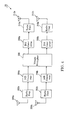
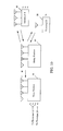
  • a transmitter 100 of base station 10 in the mode of the present embodiment includes a modulator 102, a transmission weight multiplier 104, D/A converters 106 (106a and 106b) and radio units 108 (108a and 108b) and transmitting antenna units 110 (110a and 110b) (transmitting antennas 1 and 2).
  • receiver 150 includes receiving antenna units 152 (152a and 152b) (receiving antennas 1 and 2), radio units 154 (154a and 154b), A/D converters 156 (156a and 156b), an interference subtractor 158, a reception weight multiplier 160 and a demodulator 162.
  • transmitter 100 two sets of data to be transmitted (to terminal A and terminal B) are modulated at modulator 102 first, then the modulated signals are multiplied by the transmission weight given by Eq. (3) at transmission weight multiplier 104.
  • base station 10 grasps all the channels in advance by feedback from relay station 20 or any other means.
  • the two signals after transmission weight multiplication at transmission weight multiplier 104 are input to respective D/A converters 106 and converted from digital signals to analog signals. Then, the signals are frequency-converted at radio units 108 to the radio-transmissible frequency bands, and transmitted from transmitting antenna units 110, respectively
  • receiver 150 the signals transmitted from relay station 20 are received at receiving antenna units 152 first, then radio units 154 convert the signals into A/D convertible frequencies, respectively, so that the analog signals are converted into digital signals at A/D converters 156.
  • interference subtraction is performed by interference subtractor 158.
  • This interference subtractor 158 is supplied with the own transmitted signals frommodulator 102 so that the signals are used as the known interference signals.
  • the channels having been multiplied on the known interference signals are also grasped, so that the signals that are produced by multiplying the channels, own transmitted signals and coefficients ⁇ and ⁇ is subtracted as the interference.
  • the signals after this interference subtraction are input to reception weight multiplier 160, where the signals are multiplied by the reception weight given by Eq. (7), then demodulated by demodulator 162, whereby the data transmitted from the terminals and reaching via the relay station are reproduced.
  • base station 10 With the above apparatus configuration of base station 10, it is possible to transmit the signals multiplied by the transmission weight suitable for MU-MIMO Two-way relaying and it is also possible to efficiently obtain the desired signal by subtracting the own transmitted signal as the interference signal and multiplying the reception weight. Further, as described above, it is also possible to provide a configuration using maximum likelihood detection on the signal after subtraction of the known interference, instead of using multiplication of the reception weight, as described above.
  • FIG. 3 Although in FIG. 3 , two antennas are provided for each of the transmitting and receiving sides, it is also possible to provide a configuration in which two antennas in all are provided and used to perform transmission and reception by switching therebetween by means of a switch because the present embodiment is not configured to perform transmission and reception simultaneously. It also goes without saying that three or more transmitting antennas and receiving antennas can be used.
  • FIG. 4 shows an apparatus configuration of relay station 20 in the present embodiment.
  • relay station 20 in the present embodiment includes receiving antenna units 200 (200a and 200b), radio units 202 (202a and 202b) and 210 (210a and 210b), A/D converters 204 (204a and 204b), a weight multiplier 206, D/A converters 208 (208a and 208b) and transmitting antenna units 212 (212a and 212b).
  • the signals transmitted from base station and two terminals 30 are received by receiving antenna units 200 of relay station 20 and frequency-converted at radio units 202 from the radio frequency to A/D convertible frequencies.
  • the signals are then converted from analog signals into digital signals at A/D converters 204, then are multiplied at weight multiplier 206 with the weight given by Eq. (6).
  • the signals are converted at D/A converters 208 from digital signals to analog signals and further frequency-converted to the radio-transmissible frequencies, which are transmitted from transmitting antenna units 212 toward base station 10 and terminals 30.
  • the power of the received signal is multiplied taking into consideration the attenuation in distance between the relay station and the base station, and the terminals. In this embodiment, this is assumed to be done at radio units 210.
  • this apparatus configuration of relay station 20 it is possible to receive the signals transmitted from base station 10 and terminals 30, multiply the received signals by weights suitable for MU-MIMO Two-way relaying and transmit the resultant signals again toward base station 10 and terminals 30, whereby it is possible to perform such control that terminals 30 can avoid receiving any signal with unknown interference mixed.
  • FIG. 4 Although in FIG. 4 , two antennas are provided for each of the transmitting and receiving sides, it is also possible to provide a configuration in which two antennas in all are provided and used to perform transmission and reception by switching therebetween by means of a switch because the present embodiment is not configured to perform transmission and reception simultaneously. Further, it is possible to use three or more transmitting antennas and receiving antennas as long as the number of antennas is equal to the number of terminals (the number of streams) that perform MU-MIMO communication simultaneously.
  • FIG. 5 shows an apparatus configuration of terminal 30 in the present embodiment.
  • terminals 30 terminals A and B in the present embodiment
  • a transmitter 300 of terminal 30 in the present embodiment includes a modulator 302, a D/A converter 304, a radio unit 306 and a transmitting antenna unit 308.
  • a receiver 350 includes a receiving antenna unit 352, a radio unit 354, an A/D converter 356, an interference subtractor 358 and a demodulator 360.
  • the data to be transmitted is modulated by modulator 302 first, then is converted by D/A converter 304 from digital signal to analog signal. Further, the signal is frequency-converted into a radio-transmissible frequency at radio unit 306 and then transmitted from transmitting antenna unit 308.
  • receiver 350 the signal received by receiving antenna unit 352 is frequency-converted to an A/D convertible frequency at radio unit 354, then the signal is converted from analog signal to digital signal by A/D converter 356. Then, interference subtractor 358 performs subtraction of interference. This interference subtractor 358 is supplied with the own transmitted signal, frommodulator 302 so that the signal is used as the known interference signal.
  • a signal that is produced by multiplying this own transmitted signal by the previously notified coefficient ⁇ from relay station 20 is subtracted as the interference signal from the received signal.
  • the signal with the interference signal thus subtracted is demodulated at demodulator 360, whereby the data transmitted from base station 10 and reaching via relay station 20 is reproduced.
  • one antenna is provided for each of transmitting and receiving sides, it is also possible to provide a configuration in which one antenna in all is provided and used to perform transmission and reception by switching therebetween by means of a switch because the present embodiment is not configured to perform transmission and reception simultaneously.
  • Each of the apparatus configurations can be realized by adding a frequency channel switch for switching between the frequency channels to be used in the first time frame and the second time frame, to the configuration illustrated in the present embodiment.
  • the base station and relay station have grasped all the channel variations in advance.
  • the base station cannot directly acquire the channel variations between the relay station and terminals, it is hence necessary to notify the base station of the channel variations between the relay station and terminals.
  • the relay station can directly receive the signals transmitted from the base station and each terminal, it is hence possible to directly know the channel with the base station and the channels with terminals. Accordingly, it is possible to provide a configuration in which transmission and reception weights (or transmission weight only) are calculated using each channel matrix estimated at the relay station so that the calculated result is notified from the relay station to the base station. With this configuration, it is possible to get through the process without calculating weights separately at the base station and the relay station, hence simplify the procedures.
  • the first embodiment was described on the MU-MIMO Two-way relaying when the transmission and reception weights based on the concept of ZF (Zero Forcing) are used. In this case, however, there are cases where noise components are emphasized in order to restore the signal to its original condition. In the second embodiment to which the present invention is applied, transmission and reception weights whose influence on noise components is taken into consideration will be shown.
  • ZF Zero Forcing
  • W TX is represented as follows.
  • is a coefficient that normalizes the transmission power of the base station and is represented as following expression.
  • the square of ⁇ MS is the power of noise of the terminals, and the second term on the right side of Eq. (24) represents a matrix composed of the off-diagonal elements of the matrix in the parentheses only.
  • W RS is represented as follows.
  • vec( ) is the reshape of the matrix inside the parentheses, given in a vector representation.
  • the first term and second term on the right side of Eq. (27) represent Kronecker products.
  • is a coefficient that normalizes the transmission power of the relay station and is represented by the following expression.
  • Math 28 ⁇ / tr W RS ⁇ ⁇ H ⁇ W TX ⁇ Q u ⁇ W TX H ⁇ H H ⁇ W RS ⁇ H + W RS ⁇ ⁇ G ⁇ Q v ⁇ G H ⁇ W RS ⁇ H + ⁇ RS 2 ⁇ W RS ⁇ ⁇ W RS ⁇ H P RS
  • W RX is represented as follows.
  • Math 29 W RX Q v ⁇ G H ⁇ W RS H ⁇ H * ⁇ H T ⁇ W RS ⁇ G ⁇ Q v ⁇ G H ⁇ W RS H ⁇ H * + ⁇ RS 2 ⁇ H T ⁇ W RS ⁇ W RS H ⁇ H * + ⁇ BS 2 ⁇ I - 1
  • the square of ⁇ BS is the power of noise of the base station.
  • the base station 10, relay station 20 and terminals 30 in the present embodiment can be realized using the same configurations described in the first embodiment. However, the weights and coefficients such as ⁇ and ⁇ , used in each weight multiplier should use those shown in the present embodiment.
  • the present invention can be applied to a configuration in which the number of transmitting and receiving antennas and the number of terminals are equal to or greater than those, by using channel matrixes corresponding to the situation.
  • a case where the number of receiving antennas in base station 10 and relay station 20 is 4 and there are four terminals each having one antenna corresponds to a mode of the above embodiment in which 2 ⁇ 2 channel matrixes are replaced by 4 ⁇ 4 matrixes and 2 ⁇ 1 transmission signal vectors are replaced by 4 ⁇ 1 vectors. With this correspondence, it is possible to use the weights described above in the same manner as those for 2 ⁇ 2 matrixes.
  • the present invention can also be applied to a case where the number of receiving antennas in base station 10 and relay station 20 is 4 and there exist a terminal having three antennas and two terminals having one antenna.
  • weights are those designated so that each stream (the modulated signal before multiplication of W TX ) transmitted from the base station can be separately received on the terminal side.
  • W TX modulated signal before multiplication of W TX
  • the interference signal for terminal A shown in FIG. 6 is u 3 , u 4 , v 3 and v 4 , which are required so as not to be mixed in the received signal of terminal A while u 1 and u 2 are the desired signals and v 1 and v 2 are both known interference. Accordingly, it is possible to provide a configuration in which, instead of separating these signals (u 1 , u 2 , v 1 and v 2 ) by the weight control at the base station and relay station, the terminals receive the signals involving (added with) these signals and removes these by the processing at the terminals so as to detect the desired signal.
  • is a coefficient that is represented by Eq. (28) to normalize the transmission power of the relay station and each channel matrix (H, G) is given as a 4 ⁇ 4 matrix in the present embodiment.
  • the received signal vector at the terminals when this weight is used is represented from Eq. (14) as follows.
  • W TX ⁇ W TX ' and noise components are neglected for simplicity.
  • is a coefficient that is represented by Eq. (25) to normalize the transmission power at the base station.
  • the first term on the right side of Eq. (31) represents the desired signal components transmitted from the base station to the terminals. Since the signal addressed to the other terminal (for example, the signal addressed to terminal A) behaves as unknown interference (to terminal B), it is necessary for the base station to perform such weight control that each terminal can avoid receiving such unknown interference.
  • control is performed such that four signals (streams) addressed to terminals are all separated and received by the terminals.
  • a weight control different from these will be described.
  • the weight control in the present embodiment is schemed so that the terminals can avoid receiving unknown interference without the need of completely separating all streams, by applying a process called block diagonalization to this channel F.
  • the block diagonalization (Block Diagonalization) suited to the present embodiment will be described hereinbelow.
  • each of F 1 and F 2 is a 2 ⁇ 4 matrix.
  • F 1 denotes the channel through which the signal is received by terminal A
  • F 2 denotes the channel through which the signal is received by terminal B.
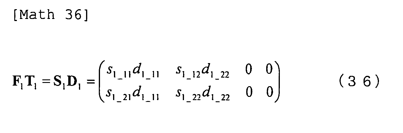
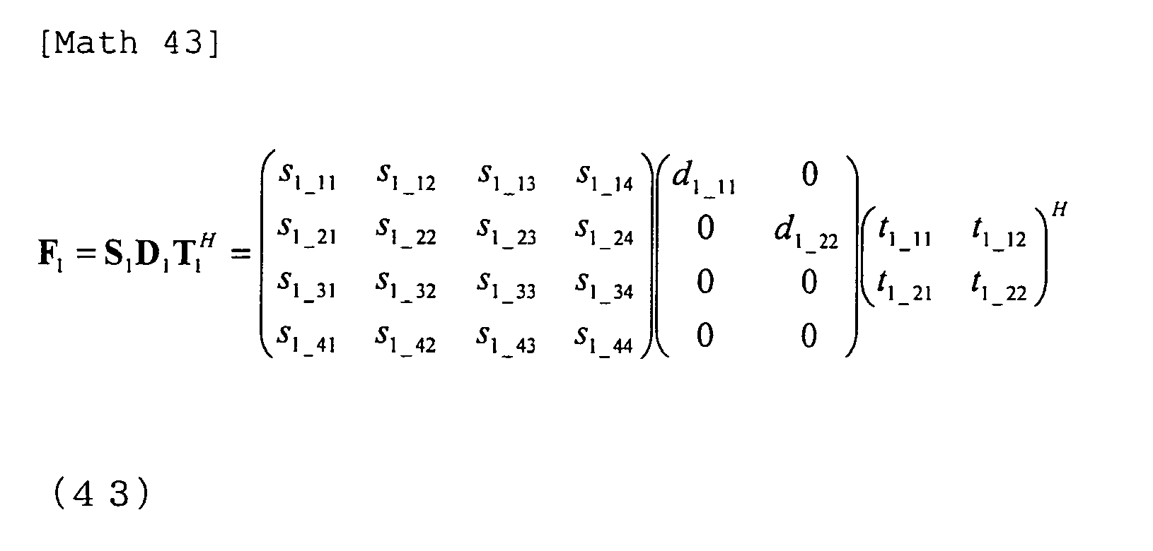
  • singular value decomposition is carried out on each of F 1 and F 2 that form the above channel F.
  • the singular value decomposition is a process of representing a mxn matrix J by the product of an mxm unitary matrix S, a m ⁇ n matrix D having 0 as its off-diagonal elements and singular values of matrix J as its diagonal elements and a complex conjugate transposed matrix of an n ⁇ n unitary matrix, T H , and this can be written as follows.
  • Math 33 J SDT H
  • F 1 and F 2 in Eq. (32) are each subjected to this singular value decomposition, F 1 and F 2 can be written as follows.
  • f 11 ′ f 11 ⁇ t 2 _ 13 + f 12 ⁇ t 2 _ 23 + f 13 ⁇ t 2 _ 33 + f 14 ⁇ t 2 _ 43
  • f 12 ′ f 11 ⁇ t 2 _ 14 + f 12 ⁇ t 2 _ 24 + f 13 ⁇ t 2 _ 34 + f 14 ⁇ t 2 _ 44
  • f 21 ′ f 21 ⁇ t 2 _ 13 + f 22 ⁇ t 2 _ 23 + f 23 ⁇ t 2 _ 33 + f 24 ⁇ t 2 _ 43
  • f 22 ′ f 21 ⁇ t 2 _ 14 + f 22 ⁇ t 2 _ 24 + f 23 ⁇ t 2 _ 34 + f 24 ⁇ t 2 _ 44
  • f 33 ′ f 31 ⁇ t 1 _ 13 + f 32 ⁇ t 1 _ 23 + f 33 ⁇ t 1
  • the signal received by terminal A is the combined signal of u 1 and u 2 without including u 3 and u 4 .
  • the signal received by terminal B is the combined signal of u 3 and u 4 without including u 1 and u 2 . That is, transmission of the signal multiplied at the base station by the block-diagonalized transmission weight makes it possible to control such that each terminal receives the signal including the desired signal for itself (the signal not separated into streams) and can avoid receiving the unknown interference which the base station transmits to the other terminal.
  • the combined signal of the desired signals, left after subtraction of the known interference signal (the second term on the right side of Eq. (31)) from the received signal may be subjected to most likelihood detection or the like to thereby separate the desired signals (streams).
  • the desired signals (streams) are separated by multiplying linear weights and received by the terminals
  • plural streams addressed to one terminal are not separated though the streams addressed to different terminals are separated by linear weights, so that this configuration enhances the possibility of obtaining good reception performance under a condition in which separation by linear processing is not suitable such as in a case where there is correlation between antennas.
  • the upper left 2 ⁇ 2 matrix and lower right 2 ⁇ 2 matrix in the matrix shown in Eq. (38) need to be grasped at terminal A and terminal B, respectively.
  • the channel estimation signal is multiplied with the same weight as that at the time of transmission of the data signal, at the base station and relay station, and the thus processed channel estimation signal is received whereby it is possible to estimate the variation of the necessary virtual channel.
  • a configuration in which instead of using maximum likelihood detection the received is subjected to a linear process such as ZF, MMSE (Minimum Mean Square Error) or the like to perform signal detection.
  • the signal after subtraction of the known interference results in the same signal with that of the first embodiment. Accordingly, it is possible to detect the desired signal by multiplying the same receiving weight as that of the first embodiment. It is also possible to perform maximum likelihood detection.
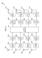
  • FIG. 7 shows an apparatus configuration of base station 10 in the present embodiment.
  • the base station 10 in the present embodiment has a configuration of the apparatus shown in FIG. 3 in which the number of antennas is increased, and the same reference numerals as in FIG. 3 are used.
  • the base station shown in FIG. 7 is configured so as to perform maximum detection on the desired signal at demodulator 162, instead of performing receiving weight multiplication. Further, in this base station, the aforementioned block-diagonalized transmission weight is multiplied in transmission weight multiplier 104.
  • FIG. 8 shows an apparatus configuration of relay station 20 in the present invention.
  • the relay station 20 in the present embodiment has a configuration of the apparatus shown in FIG. 4 in which the number of antennas is increased, and the same reference numerals as in FIG. 4 are used.
  • the weight multiplied at weight multiplier 206 is one that can be represented by the same expression as that shown in the first embodiment.
  • FIG. 9 shows an apparatus configuration of terminal 30 in the present invention.
  • the terminal 30 in the present embodiment has a configuration of the apparatus shown in FIG. 5 in which the number of antennas is increased, and the same reference numerals as in FIG. 5 are used.
  • the signal multiplied by the transmission weight that has been block-diagonalized as shown above is transmitted, whereby it is possible to perform such a control that the terminal can avoid receiving unknown interference without completely separating the desired signals into individual streams.
  • the third embodiment was described on the case where the weight that has been calculated by block diagonalization is used at the base station and the weight based on the ZF scheme is used at the relay station. However, it is also possible to perform signal transmission by using a weight calculated using block diagonalization at the relay station similarly to the base station.
  • the fourth embodiment shows a case where a weight calculated using block diagonalization is used also in the relay station.
  • the second term in this Eq. (40) is the term, representing a signal that is produced by multiplying the signal transmitted from each terminal and received at relay station in frame 1 by a weight at the relay station and that is transmitted from the relay station in frame 2, and including the known interference transmitted by the terminal and unknown interference transmitted from the other terminal.
  • W RS is calculated using block diagonalization.
  • is a coefficient that is given by Eq. (28) to normalize the transmission power at the relay station.
  • Eq. (41) the second term of Eq. (40) is rewritten so that the relay station weight W RS is given by the product of W' RS1 and W' RS2 .
  • W' RS1 is a matrix that performs block diagonalization by regarding G T multiplied from the left as the virtual channel F in the third embodiment
  • W' RS2 is a matrix that performs block diagonalization by regarding G multiplied from the right as the virtual channel F in the third embodiment. That is, G T W' RS1 creates a block-diagonalized matrix as shown in Eq. (38) and similarly W' RS2 G creates also a block-diagonalized matrix.
  • G 1 and G 2 are both a 4 ⁇ 2 matrix.
  • G 1 and G 2 are both a 4 ⁇ 2 matrix.
  • the results as follows are obtained.
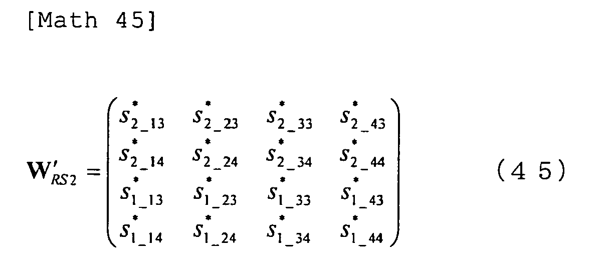
  • W' RS2 is obtained as follows.
  • W RS ⁇ 2 ⁇ s 2 _ 13 * s 2 _ 23 * s 2 _ 33 * s 2 _ 43 * s 2 _ 14 * s 2 _ 24 * s 2 _ 34 * s 2 _ 44 * s 1 _ 13 * s 1 _ 23 * s 1 _ 33 * s 1 _ 43 * s 1 _ 14 * s 1 _ 24 * s 1 _ 34 * s 1 _ 44 *
  • W' RS2 is obtained by the above procedure, and transmitted together with W' RS1 from each terminal in frame 1 so as to be able to block diagonalize the virtual channel matrix through which the signal transmitted from the relay station in frame 2, whereby it is possible to perform such a control that each terminal can avoid receiving unknown interference transmitted from the other terminal, without having the known signal (interference) transmitted from its own, separated into different streams. Then, at the terminal, it is possible to subtract the known interference by grasping the minor matrix included in the received signal of itself, of the block-diagonalized matrix.
  • the terminal receiving the thus block-diagonalized signal it is possible to detect the desired signal by performing maximum likelihood detection, multiplication of the reception weight or the like after subtraction of the known interference, similarly to the third embodiment. Also in the base station, it is possible to detect the desired signal by performing maximum likelihood detection, multiplication of the reception weight or the like after subtraction of the known interference, similarly to the embodiments heretofore.
  • the present embodiment has been described taking an example in which a weight making use of block diagonalization is used also in the relay station.
  • the apparatuses of the base station, relay station and terminals can be realized by the same configurations as those illustrated in the third embodiment ( FIGS. 7 , 8 and 9 ).
  • the weight making use of block diagonalization was demonstrated in the cases where the numbers of receiving antennas in base station 10 and relay station 20 are each four while two terminals each having two antennas exist or each terminal has the same number of antenna with others.
  • the MU-MIMO Two-way Relaying according to the present invention can support a case where there are terminals having different numbers of antennas as shown in FIG. 10 .
  • the fifth embodiment will be described on the weight control in such a case.
  • control in which all the streams are separated as shown in the first and second embodiments can be applied similarly to the case shown in FIG. 10 .
  • control using a weight making use of block diagonalization as illustrated in the third and fourth embodiments can also be applied. In this case, however, since the number of desired signals (streams) and the number of interference (streams) are different between terminals A and B, it is necessary to perform block diagonalization taking this into account.
  • F 1 that forms the virtual channel matrix of Eq. (32) as a 3 ⁇ 4 matrix
  • F 2 represents the channel through which the signal received at terminal B passes.
  • the weight control using the block diagonalization at the relay station as in the fourth embodiment can also be applied, and hence it is possible to realize the MU-MIMO Two-way Relaying when plural terminals having different numbers of antennas exist as shown in FIG. 10 .
  • the MU-MIMO Two-way Relaying according to the present invention does not require that all the terminals have the same number of antennas, and can perform efficient transmission via a relay station even under a condition that plural terminals having different number of antennas exist.
  • the apparatus equipped with plural antennas to perform bidirectional communication with two terminals is called a base station and the apparatus equipped with plural antennas for relaying bidirectional communication between the base station and the terminals is called a relay station.
  • the present invention can be applied to a system in which a terminal having plural antennas performs bidirectional communication with plural terminals.
  • an apparatus that normally operates as a base station may be adapted to function as a relay station.
  • the present invention can be applied even to a case where a terminal including a plurality of antennas operates as a relay station.
  • optimizing criteria such as maximizing the transmission rate, minimizing MSE (Mean Square Error and the like) are set up first, then the formulas of the respective weights that satisfy those criteria are calculated. Since the thus obtained base station transmission weight and relay station transmission weight are correlated to each other, it is impossible to obtain the optimal values by a single operation, hence it is necessary to perform optimization by repeated operations.
  • one of the weights is initialized and the other weight is calculated using the initialized weight. Then, the process for updating the value of the other weight (the weight initialized first) using the calculated weight is repeated until the two weight values converge.
  • the thus obtained final values can be regarded as the respective optimal weights under the optimizing criteria.
  • the base station transmission weight and relay station transmission weight according to the present invention can be determined by such an iteration process too.

Landscapes

  • Engineering & Computer Science (AREA)
  • Computer Networks & Wireless Communication (AREA)
  • Signal Processing (AREA)
  • Physics & Mathematics (AREA)
  • Mathematical Physics (AREA)
  • Power Engineering (AREA)
  • Mobile Radio Communication Systems (AREA)
  • Radio Relay Systems (AREA)
  • Radio Transmission System (AREA)

Abstract

In a radio communication system performing bidirectional communication between a base station having plural transmitting and receiving antennas and plural terminals using the same frequency via a relay station having plural transmitting and receiving antennas, the base station and terminals transmit signals to the relay station simultaneously in a first time frame, the relay station which receives the transmitted signals in the first time frame transmits signals generated by multiplying the received signals by a relay station transmission weight, to the base station and the plural terminals in a second time frame. With this, it is possible to provide a communication system and the like, which can realize MU-MIMO bidirectional communication between a base station including plural antennas and plural terminals, with a lower amount resources when the communication is performed via a relay station.

Description

    Technical Field
  • The present invention relates to a radio communication system and the like in which a base station and terminals perform bidirectional communication using the same frequency, via a relay station including plural transmitting and receiving antennas.
  • Background Art
  • In order to solve the stringency of frequency resources with recent increase in data traffic, new radio frequencies are allotted for mobile communication, and construction of new mobile communication systems (for example, IMT-Advanced system) that use newly allocated radio frequency ranges has been progressed. For such a new mobile communication system, a higher frequency band than those allotted to the conventional systems is allotted as the frequency band. However, the higher the frequency of the signal is, the more the signal attenuates, and the coverage becomes narrower than the conventional systems. As a means for solving this problem, there is method of providing a relay station that relays communication between the base station and terminals within a cell.
  • Examples of the relay stations may include one that merely amplifies the received signal and transmits the amplified signal (Amplify-and Forward: AF type), one that once demodulates and decodes the received signal and re-demodulates and transmits the signal if the signal is free from error (Decode-and-Forward: DF type), and others. When the base station and terminals that are located away from the base station (terminals located at the cell-edge boarder), communicate via the relay station, it is possible for the relay station to keep up the cell coverage that is equivalent to that of the conventional system, without degrading reception performance of those terminals.
  • FIG. 11 shows an example of a radio communication system including such a relay station. As shown in FIG. 11, a base station 90 and a terminal 94 are connected via a relay station 92. Here, upon transmission of a signal from base station 90 to terminal 94, two frames are required to transmit the signal corresponding to one frame when the signal is relayed via relay station 92.
  • Similarly, upon transmission of a signal fromterminal 94 to base station 90, two frames are required to transmit the signal corresponding to one frame when the signal is relayed via relay station 92. Accordingly, when signals are exchanged between base station 90 and terminal 94 using the same frequency, time resource for four frames are required. This causes the problem of lowering transmission efficiency.
  • As the measures against this problem, a bidirectional communication method called Two-way relaying or Bi-direction relaying has been proposed. In this method, for example, base station 90 transmits a signal to relay station 92 first and then the terminal transmits a signal to the relay station in the next frame, as shown in FIG. 12. Here, for description simplicity, the channel variation affecting each signal is omitted.
  • Relay station 92 combines the signals received in the different frames and broadcasts the combined signal in the third frame to base station 90 and terminal 94. In this third frame, base station 90 and terminal 94 each receive the mixture of the two signals. So it is usually impossible to reproduce the original data.
  • However, in this case, since base station 90 and terminal 94 grasp respective own transmitted signals, it is possible to detect the signal transmitted from the opposite side by subtracting the own transmitted signal from the received signal. As a result, it is possible to realize bidirectional communication via relay station 92, which usually requires four frames, by three frames, hence improves efficiency of frequency use.
  • Further, though FIG. 12 shows a configuration in which base station 90 and terminal 94 transmit to relay station 92 using different frames, it is possible to provide a configuration in which base station 90 and terminal 94 perform transmission to relay station 92 at the same time. It is possible in this case to realize bidirectional communication via relay station 92 by two frames.
  • Moreover, though description herein was made referring to an AF type configuration in which no decoding of received signals is performed at relay station 92, it is possible to provide a configuration in which, when each signal can be decoded at relay station 92 (when base station 90 and terminal 94 transmit signals using different frames, when relay station 92 has a plurality of receiving antennas though base station 90 and terminal 94 transmit signal simultaneously, or in other cases) the signals are once decoded at relay station 92, and the two decoded sets of data are synthesized and broadcast to the base station and the terminal. In this case, a technique is used in which the signal obtained by taking the exclusive disjunction of two sets of data transmitted from base station 90 and terminal 94 is modulated and broadcast to each of these.
  • Use of this method makes it possible to cut down the required time resource even when communication is performed via relay station 92, hence it is possible to realize efficient bidirectional communication.
  • A technique for applying this Two-way relaying (Bi-directional relaying) to MIMO (Multiple-Input Multiple -Output) communication is demonstrated in non-patent document 1.
  • Discussed in non-patent document 1 is a case where the base station, relay station and terminal each have two antennas so that two streams of data (different data from each antenna) are transmitted from the base station and terminal. In this case, non-patent document 1 discloses a configuration (FIG. 13) in which when the relay station transmits a signal toward the base station and terminal, the signal is multiplied with a transmission weight, and the base station and terminal that receive this signal multiplies a reception weight on the signal after subtraction of the known interference (the own transmitted signal).
  • In MIMO communication between the base station and one terminal, the base station and terminal each grasp two transmitted signals of their own (u1 and u2 for the base station and v1 and v2 for the terminal) so as to be able to subtract signals obtained by multiplying these signals by a channel variation or the like, from the received signals. Further, the signal obtained after subtraction of theself-interference (the known interference transmitted by itself) from the received signal is the sum of the two desired signals (v1 and v2 for the base station and u1 and u2 for the terminal) and noise, hence can be processed in the same manner as in normal MIMO (here, signal separation by multiplying a reception weight. Multiplication of the transmission and reception weights as this makes it possible to perform signal detection at the base station and terminal with a favorable performance, hence realize efficient bidirectional communication.
  • Non-patent document 2 demonstrates a technique for applying Two-way relaying (Bi-directional relaying) to multi-user MIMO (Multi-User-MIMO: MU-MIMO) communication in which a base station performs communication with plural terminals at the same time. Discussed in this non-patent document 2 is bidirectional communication using three units of time resources (frames) when the base station and relay station each have two antennas while two terminals each having one antenna exist (FIG. 14).
  • As shown in FIG. 14, at the same time that the signal addressed from the base station to terminal A is transmitted to the relay station, the signal addressed from terminal A to the base station is transmitted to the relay station in the first frame. At this time, the signal transmitted from terminal A to the relay station is also received and demodulated at terminal B so that this demodulated signal will be used afterwards as the known interference signal.
  • Next, in the second frame, at the same time that the signal addressed from the base station to terminal B is transmitted to the relay station, the signal addressed from terminal B to the base station is transmitted to the relay station. At this time, the signal transmitted from terminal B to the relay station is also received and demodulated at terminal A so that this demodulated signal will be used afterwards as the known interference signal.
  • Finally, in the third frame, the relay station demodulates, decodes and modulates once again the signals received from the base station and the two terminals and combines them into a signal, which is broadcasted to the base station and two terminals. The base station and two terminals having received this signal need to subtract signals forming interference in order to detect respective necessary signals. Since the base station grasps its own signals transmitted to the two terminals, it is possible to perform this subtraction to thereby extract the desired signal.
  • Also, in the two terminals, each grasps the own transmitted signal and has received the signal transmitted by the other terminal so that it is possible to subtract this as the interference signal. In performing MU-MIMO communication, each terminal usually grasps its own transmitted signal only, so that the terminal cannot subtract interference correctly, resulting in difficulty in realizing bidirectional communication. However, as in non-patent document 2, the signal transmitted from one terminal is intentionally received and demodulated by the other, whereby it is possible for each terminal to grasp the signal transmitted from the other as the known interference and use it for subtraction.
  • Prior Art Documents Non-patent Documents
  • Non-patent Document 1: N. Lee et al, "Linear Precoder and Decoder Design for Two-Way AF MIMO Relaying System, "VTC Spring 2008, May 2008.
    Non-patent Document 2: L. Weng et al, "MU-MIMO Relaying System with Self-interference Cancellation" WCNC 2007, Mar. 2007.
  • Summary of the Invention Problems to be Solved by the Invention
  • In MU-MIMO environment, the own transmitted signal, the signal transmitted by the other terminal and the signal transmitted to the other terminal by the base station are combined as interference with the desired signal. However, each terminal knows its own transmitted signal only, so that it is impossible to appropriately subtract the inference (the signal transmitted by the other terminal and the signal transmitted to the other terminal by the base station), hence it is impossible to realize bidirectional communication using the transmission and reception weights as shown in non-patent document 1.
  • On the other hand, use of the technique shown in non-patent document 2 enables each terminal to grasp the interference signal to be subtracted (the signal transmitted by the other terminal) under MU-MIMO environment, but the terminal needs to perform a process of receiving and demodulating the signal that is transmitted from the other terminal to the relay station during the signal is being transmitted, hence it is difficult to realize when the terminals are located distant from each other. Further, this process is not preferable in view of power consumption at the terminal and from a privacy viewpoint for the transmitted data of the terminals. Moreover, the technique described in non-patent document 2 needs three units of time resources, so that it is desired to realize a highly efficient system for which the required resources are further cut down.
  • In view of the problems described above, the object of the present invention is to provide a communication system and the like, which realize MU-MIMO bidirectional communication between a base station having plural antennas and plural terminals efficiently with a lower amount of resources when the communication is performed via a relay station.
  • Means for Solving the Problems
  • In view of the above problems, the radio communication system according to the present invention is a radio communication system performing bidirectional communication between a base station including a plurality of transmitting and receiving antennas and a plurality of terminals using a same frequency via a relay station having a plurality of transmitting and receiving antennas, and is characterized in that the base station and plural terminals transmit signals to the relay station simultaneously in a first time frame, the relay station includes: a receiving means for receiving the signals transmitted in the first time frame as received signals; and, a transmitting means for generating a transmitted signal by multiplying the received signals by a relay station transmission weight WRS and transmitting the transmitted signal to the base station and plural terminals in a second time frame.
  • The radio communication system of the present embodiment is characterized in that the relay station transmission weight WRS is generated at least based on a channel between the relay station and terminals.
  • The radio communication system of the present embodiment is characterized in that the signal transmitted from the base station in the first time frame is a signal that is produced by multiplying a modulated signal by a base station transmission weight WTX.
  • The radio communication system of the present embodiment is characterized in that the base station transmission weight WTX is generated at least based on a channel between the base station and the relay station, or the channel between the relay station and terminals.
  • The radio communication system of the present embodiment is characterized in that the relay station transmission weight WRS and the base station transmission weight WTX are generated so as to have the transmitted streams from the base station all separated and received by individual terminals.
  • The radio communication system of the present embodiment is characterized in that each terminal having received the signal transmitted from the relay station in the second time frame, generates an interference signal based on the signal that the terminal transmitted in the first time frame and subtracts the generated interference signal from the received signal to detect the signal transmitted from the base station in the first frame.
  • The radio communication system of the present embodiment is characterized in that the base station having received the signal transmitted from the relay station in the second time frame, generates an interference signal based on the signal that the base station transmits in the first time frame and subtracts the generated interference signal from the received signal and multiplies the signal after subtraction of the interference signal by a reception weight WRX to detect the signal transmitted from the terminal.
  • The radio communication system of the present embodiment is characterized in that the reception weight WRX is generated at least based on the channel between the base station and the relay station, or the channel between the relay station and the terminals.
  • The radio communication system of the present embodiment is characterized in that the relay station transmission weight WRS, the base station transmission weight WTX and the reception weight WRX are represented by equations (3), (5), (6), (8) and (9), where H is the channel matrix between the base station and the relay station, G is the channel matrix between the relay station and the plural terminals, PBS is the total transmission power of the base station, PRS is the total transmission power of the relay station, PMS is the sum of transmission powers of the terminals, the covariance matrix of the transmitted signal from base station before multiplication of the first transmission weight WTX is the unit matrix, M is the total number of antennas of the terminals, the square of σRS is the noise power at the relay station.
  • The radio communication system of the present embodiment is characterized in that the relay station transmission weight WRS, the base station transmission weight WTX and the reception weight WRX are represented by equations (23) to (29), where H is the channel matrix between the base station and the relay station, G is the channel matrix between the relay station and the plural terminals, PBS is the total transmission power of the base station, PRS is the total transmission power of the relay station, PMS is the sum of transmission powers of the terminals, Qu is the covariance matrix of the transmitted signal from the base station before multiplication of the base station transmission weight WTX, Qv is the covariance matrix of the transmitted signal of base station, M is the total number of antennas of the terminals, the square of σBS is the noise power at the base station, the square of σRS is the noise power at the relay station and, the square of σMS is the noise power of the terminals.
  • The radio communication system of the present embodiment is characterized in that all the plural terminals have the same number of antennas.
  • The radio communication system of the present embodiment is characterized in that the plural terminals have a plurality of antennas.
  • The radio communication base station of the present invention is a base station having a plurality of transmitting and receiving antennas and performing bidirectional communication with a plurality of terminals using the same frequency via a relay station having a plurality of transmitting and receiving antennas, and includes: a transmitting means for transmitting a signal addressed to the plural terminals toward the relay station in a first time frame; and a receiving means for receiving the signal transmitted from the relay station in a second time frame.
  • The base station of the present invention is characterized in that the transmitting means transmits a signal that is produced by multiplying a modulated signal by a base station transmission weight WTX.
  • The base station of the present invention is characterized in that the base station transmission weight WTX is generated at least based on a channel between the base station and the relay station, or a channel between the relay station and the terminals.
  • The base station of the present invention is characterized in that the base station transmission weight WTX is generated so that the transmitted streams from the base station are all separated and received by individual terminals.
  • The base station of the present invention further includes: an interference signal generating means for generating an interference signal based on the signal that the base station itself transmits in the first time frame; and, an interference subtracting means for subtracting the generated interference signal from the signal received by the receiving means in the second time frame.
  • The base station of the present invention further includes: a reception weight multiplying means for multiplying the signal after subtraction of the interference signal by the interference subtracting means by a reception weight WRX; and, a means for detecting the transmitted signal from the terminals after multiplication of the reception weight WRX.
  • The base station of the present invention is characterized in that the reception weight WRX is generated at least based on the channel between the base station and the relay station, or the channel between the relay station and the terminals.
  • The relay station of the present invention is a relay station relaying bidirectional communication between a base station having a plurality of transmitting and receiving antennas and a plurality of terminals using a same frequency, and includes: a receiving means for receiving the signals transmitted from the base station and the terminals in the first time frame as received signals; and, a transmitting means that transmitting a signal generated by multiplying the received signals in the first time frame by a relay station transmission weight WRS as the transmitted signals in a second time frame.
  • The relay station is characterized in that the relay station transmission weight WRS is generated at least based on the channel between the relay station and the terminals.
  • The relay station is characterized in that the relay station transmission weight WRS is generated in such a manner that the transmitted streams from the base station are all separated and received by individual terminals.
  • The terminal of the present invention is a terminal performing bidirectional communication with a base station having a plurality of transmitting and receiving antennas, via a relay station having a plurality of transmitting and receiving antennas using a same frequency as that of the base station and other terminals, and includes: a transmitting means for transmitting a signal addressed to the base station toward the relay station in a first time frame; and a receiving means for receiving the signal transmitted from the relay station in a second time frame.
  • The terminal of the present invention further includes: an interference signal generating means for generating an interference signal based on the signal that the terminal itself transmits in the first time frame; and an interference subtracting means for subtracting the generated interference signal from the received signal in the second time frame.
  • Effect of the Invention
  • Use of the present invention makes it possible to realize MU-MIMO bidirectional communication between a base station having plural antennas and terminals, efficiently with a lower amount of resources (the number of frames: 2) when the communication is performed via a relay station. Specifically, it is possible to perform such control that each terminal can avoid receiving the signal involving unknown interference, by multiplying the transmitted signals by associated weights suitable for bidirectional communication under MU-MIMO environment. This weight multiplying control enables each terminal to receive the combined signal consisting of the desired signal and the known interference only, so that it is possible to efficiently detect the desired signal by subtracting the known interference. Further, also on the base station side, it is possible to subtract the known interference signal and obtain good reception performance by multiplying a reception weight.
  • Brief Description of Drawings
    • [FIG. 1] is a diagram for illustrating the outline of a radio communication system in the first embodiment.
    • [FIG. 2] is a diagram for illustrating the outline of a radio communication system in the first embodiment.
    • [FIG. 3] is a diagram for illustrating the configuration of a base station in the first embodiment.
    • [FIG. 4] is a diagram for illustrating the configuration of a relay station in the first embodiment.
    • [FIG. 5] is a diagram for illustrating the configuration of a terminal in the first embodiment.
    • [FIG. 6] is a diagram for illustrating the operation in the third embodiment.
    • [FIG. 7] is a diagram for illustrating the configuration of a base station in the third embodiment.
    • [FIG. 8] is a diagram for illustrating the configuration of a relay station in the third embodiment.
    • [FIG. 9] is a diagram for illustrating the configuration of a terminal in the third embodiment.
    • [FIG. 10] is a diagram for illustrating the operation in the fifth embodiment.
    • [FIG. 11] is a diagram for illustrating the operation of a conventional radio communication system.
    • [FIG. 12] is a diagram for illustrating the operation of a conventional radio communication system.
    • [FIG. 13] is a diagram for illustrating the operation of a conventional radio communication system.
    • [FIG. 14] is a diagram for illustrating the operation of a conventional radio communication system.
    Modes for Carrying Out the Invention
  • Subsequently, a radio communication system 1 to which the present invention is applied will be described. FIG. 1 is a diagram for illustrating the outline of a radio communication system 1. As shown in FIG. 1, in radio communication system 1, terminals 30 (terminal A and terminal B) are connected to a base station 10 via a relay station 20.
  • Now, the outline of radio communication system 1 to which the present invention is applied will be described. That is, the present invention relates to a method of realizing MU-MIMO bidirectional communication between a base station having a plurality of antennas and plural terminals by way of a relay station, in an efficient manner with a lower amount of resources.
  • Specifically, as shown in FIG. 2, base station 10 and terminals 30 (terminals A and B) each transmit a signal to relay station 20 in the first time frame. Then, in the second time frame, relay station 20 broadcasts a signal to base station 10 and two terminals 30. Upon this, each of base station 10 and relay station 20 multiply the signal to be transmitted by a corresponding weight (WTX, WRS) suitable for bidirectional communication under the MU-MIMO environment so as to perform control such that each terminal can avoid receiving any signal mixed with unknown interference. With this weight multiplying control, it is possible for each terminal to receive a combined signal consisting of the desired signal and the known interference only, hence detect the desired signal efficiently by subtracting the known interference.
  • That is, u1 is obtained in terminal A by interference subtraction while u2 is obtained in terminal B by interference subtraction. Further, when if the terminals are equipped with a plurality of antennas, it is possible to implement maximum likelihood detection on the signal after subtraction of the known interference. Then, it is also possible to exchange signals multiplied by a weight.
  • Further it is possible to subtract the known interference signal also on the base station side, and besides it is possible to detect the signals transmitted from the terminals, by multiplying a reception weight (WRX). That is, in frame 2, when the signal after subtraction of the interference subtracted is multiplied by WRX, v1 and v2 will be obtained at base station 10. It is also possible in base station 10 to implement maximum likelihood detection on the signal after subtraction of the known interference and obtain good reception performance.
  • By applying the present invention as above, it is possible to efficiently realize MU-MIMO Two-way relaying with a lower amount of time resources (the number of frames: 2) even when the relay station does not have as many antennas as that required for decoding the signals (the signals transmitted from the base station and terminals) received in frame 1.
  • [The First Embodiment]
  • Then, the first embodiment to which the present invention is applied will be described. The first embodiment shows a case of MU-MIMO Two-way relaying where use is made of transmission and reception weights that make compensation so as to restore the received signal to its original state (to the signal corresponding to the transmitted signal) based on the concept of ZF (Zero Forcing).
  • To begin with, the mathematical representation of three weights WTX, WRS and WRX shown in FIG. 2 will be given hereinbelow. Here, base station 10 and relay station 20 each have two antennas while two terminals 30 each have one antenna. In FIG. 2, the matrix that represents the channel variation affecting the signal that is being transmitted from base station 10 to relay station 20 is assumed as H, and the reverse (from relay station 20 to base station 10) is assumed as HT, the transpose of H. Further, the matrix that represents the channel variation affecting the signal that is being transmitted from terminals 30 (Terminal A and terminal B) to relay station 20 is assumed as G, and the reverse (from relay station 20 to terminals 30) is assumed as GT, the transpose of G.
  • Detailedly describing, the channel variation affecting the signal that is being transmitted from antenna 1 of base station 10 to antenna 1 of relay station 20 is h11, the channel variation from antenna 1 of base station 10 to antenna 2 of relay station 20 is h21, the channel variation from antenna 2 of base station 10 to antenna 1 of relay station 20 is h12 and the channel variation from antenna 2 of base station 10 to antenna 2 of relay station 20 is h22.
  • Further, the channel variation affecting the signal that is being transmitted from the antenna of terminal A to antenna 1 of relay station 20 is g11, the channel variation from the antenna of terminal A to antenna 2 of relay station 20 is g12, the channel variation from the antenna of terminal B to antenna 1 of relay station 20 is g12 and the channel variation from the antenna of terminal B to antenna 2 of relay station 20 is g22. These channel variations can be given as the following expression, and base station 10 and relay station 20 are assumed to grasp these matrixes beforehand. Math 1 H = h 11 h 12 h 21 h 22
    Figure imgb0001
    Math 2 G = g 11 g 12 g 21 g 22
    Figure imgb0002
  • In this way, when the channel variations between base station 10 and relay station 20 and between terminals 30 and relay station 20 are given by matrixes such as H and G, the weights (WTX, WRS and WRX) suitable for the MU-MIMO Two-way relaying of the present invention are given as follows: Math 3 W TX = α H - 1 G
    Figure imgb0003
  • Here, α is a coefficient that normalizes the transmission power of the base station and is represented by the following equation. Math 4 α = / tr H - 1 G Q u H - 1 G H P BS
    Figure imgb0004
  • Here, PBS represents the total transmission power of the base station, Qu the covariance matrix of the signal (before multiplication of WTX) transmitted from the base station and tr(X) represents the trace (the sum of the diagonal components) of matrix X. Further, when it is assumed that the powers of the two signals (before multiplication of WTX) transmitted from the base station are equal. When given as Qu=(PBS/M)I, then α can be represented as follows. Math 5 α = / tr H - 1 G H - 1 G H M
    Figure imgb0005
  • Here, M represents the number of antennas (the number of terminals). In this case, M is "2". I is the unit matrix. Math 6 W RS = β G T - 1 G - 1
    Figure imgb0006
  • Further, β is a coefficient that normalizes the transmission power of the relay station and is represented by the following expression. Here, PRS represents the total transmission power of the relay station, Qv the covariance matrix of the signal transmitted from the two terminals and the square of σRS the power of noise at the relay station. G* represents the complex conjugate matrix of matrix G. Math 7 β = / tr α 2 G T - 1 Q u G * - 1 + G T - 1 Q v G * - 1 + σ RS 2 G T - 1 G - 1 G H - 1 G * - 1 P RS
    Figure imgb0007
  • Here, it is assumed that Qu=(PBS/M)I and the powers of the two signals transmitted from the two terminals are equal to each other. When given as Qv=(PMS/M)I, then β can be represented as follows. Here, PMS represents the total transmission power of the terminals (the sum of the transmission powers of the two terminals). Math 8 β = / tr α 2 P RS / M G T - 1 G * - 1 + P MS / M G T - 1 G * - 1 + σ RS 2 G T - 1 G - 1 G H - 1 G * - 1 P RS
    Figure imgb0008
  • When the relay station weight shown in Eq. (6) is used, the reception weight at the base station is given as follows. Math 9 W RX = G T H T - 1
    Figure imgb0009
  • Shown as follows are the received signals at base station 10 and two terminals 30 when the transmission and reception weights given by the above Eqs. (3) to (9) are used. Here, the transmission signal addressed from base station 10 to terminal A is u1, the transmission signal addressed from the base station to terminal B is u2, the transmission signal addressed to terminal A is v1 and the transmission signal addressed to terminal B is v2. For description simplicity, the noise component is omitted. Math 10 u = u 1 u 2
    Figure imgb0010
    Math 11 v = v 1 v 2
    Figure imgb0011
  • First, the signal yRS that the relay station receives in the first frame of FIG. 2 is represented as follows. Math 12 y RS = HW TX u + Gv
    Figure imgb0012
  • Then, the signal XRS that the relay station transmits in the second frame is represented as follows. Math 13 x RS = W RS HW TX u + Gv
    Figure imgb0013
  • The signal given by this Eq. (13) passes through the channel and is received at the terminals as follows. Math 14 y MS = G T W RS HW TX u + Gv = G T β G T - 1 G - 1 H α H - 1 Gu + Gv = α β u + β v = α β u 1 + β v 1 α β u 2 + β v 2
    Figure imgb0014
  • As understood from this Eq. (14), when the weights of the present invention are used, terminal A receives the combined signal of the desired signal u1 and the known interference signal v1 that was transmitted by itself without mixture of an unknown interference signal. Accordingly, it is possible to extract the desired signal u1 by subtracting the known interference signal v1 multiplied by transmission power normalizing coefficient β, from the received signal.
  • Similarly, since terminal B also receives the combined signal of the desired signal u2 and the known interference signal v2 that was transmitted by itself, in which no unknown interference signal is mixed, it is possible to extract the desired signal u2 by subtracting the known interference signal v2 multiplied by transmission power normalizing coefficient β, from the received signal. Here, the transmission power normalizing coefficient β needs to be notified from relay station 20 to each terminal 30.
  • In the above way, the transmission signal is multiplied at the base station, with the transmission weight represented by Eq. (3), and the transmission signal is multiplied at relay station 20, with the weight represented by Eq. (6), whereby it is possible to perform control such that each terminal can avoid receiving any signal involving unknown interference. That is, each terminal 30 can receive the combined signal consisting of the desired signal and the known interference only, hence it is possible to detect the desired signal by subtracting the known interference.
  • Further, the signal represented by Eq. (11) is received at the base station as the signal yBS as follows. Math 15 y BS = H T W RS HW TX u + Gv = H T β G T - 1 G - 1 H α H - 1 Gu + Gv = H T G T - 1 α β u + β v
    Figure imgb0015
  • In the base station, both u1 and u2 are known so that it is possible to subtract them as the interference component from the received signal. From Eq.(15), the interference component is subtracted, the result is as follows. Math 16 y ^ BS = β H T G T - 1 v
    Figure imgb0016
  • Multiplying this by the reception weight represented by Eq. (9) produces Math 17 y ^ BS = β W RX H T G T - 1 v = β G T H T - 1 H T G T - 1 v = β v
    Figure imgb0017

    Accordingly, it is possible to obtain the desired signal v. In this case, extraction of the desired signal is performed by subtracting the interference component from the received signal given by Eq. (15) first then multiplying the reception weight given by Eq. (9). However, it is also possible to extract the desired signal in the opposite order, or by multiplying a reception weight and then subtracting the interference component. The reception weight at this time may be the same as that given by Eq. (9).
  • As described above, by multiplying the signals in base station 10 and relay station 20 by the transmission weights according to the present embodiment, it is possible to perform such control that each terminal 30 can avoid receiving any signal with unknown interference mixed, hence it is possible to realize MU-MIMO Two-way relaying in an efficient manner by performing subtraction of the known interference signal. Further, it is also possible at base station 10 to obtain the desired signal by performing subtraction of the interference signal and multiplication of the received weight.
  • Further, though description herein was given by showing an example in which the desired signal transmitted from the terminal is detected in the base station by multiplying the received signal after subtraction of the known interference by the reception weight, maximum likelihood detection (Maximum Likelihood Detection: MLD) may be preformed on the signal after subtraction of interference without performing multiplication of any reception weight. This maximum likelihood detection is a method of detecting the signal by multiplying all the transmission signal candidates and the channel estimate and selecting the transmission signal candidate of which the result of the multiplication is the closest to the received signal, and this method can produce a better reception performance though the amount of operation is increased.
  • Now, the apparatus configuration of base station 10 in the mode of the present embodiment is shown in FIG. 3. As shown in FIG. 3, a transmitter 100 of base station 10 in the present embodiment includes a modulator 102, a transmission weight multiplier 104, D/A converters 106 (106a and 106b) and radio units 108 (108a and 108b) and transmitting antenna units 110 (110a and 110b) (transmitting antennas 1 and 2).
  • On the other hand, receiver 150 includes receiving antenna units 152 (152a and 152b) (receiving antennas 1 and 2), radio units 154 (154a and 154b), A/D converters 156 (156a and 156b), an interference subtractor 158, a reception weight multiplier 160 and a demodulator 162.
  • In transmitter 100, two sets of data to be transmitted (to terminal A and terminal B) are modulated at modulator 102 first, then the modulated signals are multiplied by the transmission weight given by Eq. (3) at transmission weight multiplier 104. Here, it is assumed that base station 10 grasps all the channels in advance by feedback from relay station 20 or any other means.
  • The two signals after transmission weight multiplication at transmission weight multiplier 104 are input to respective D/A converters 106 and converted from digital signals to analog signals. Then, the signals are frequency-converted at radio units 108 to the radio-transmissible frequency bands, and transmitted from transmitting antenna units 110, respectively
  • On the other hand, at receiver 150, the signals transmitted from relay station 20 are received at receiving antenna units 152 first, then radio units 154 convert the signals into A/D convertible frequencies, respectively, so that the analog signals are converted into digital signals at A/D converters 156.
  • Then, interference subtraction is performed by interference subtractor 158. This interference subtractor 158 is supplied with the own transmitted signals frommodulator 102 so that the signals are used as the known interference signals. In this case, the channels having been multiplied on the known interference signals are also grasped, so that the signals that are produced by multiplying the channels, own transmitted signals and coefficients α and β is subtracted as the interference. The signals after this interference subtraction are input to reception weight multiplier 160, where the signals are multiplied by the reception weight given by Eq. (7), then demodulated by demodulator 162, whereby the data transmitted from the terminals and reaching via the relay station are reproduced.
  • With the above apparatus configuration of base station 10, it is possible to transmit the signals multiplied by the transmission weight suitable for MU-MIMO Two-way relaying and it is also possible to efficiently obtain the desired signal by subtracting the own transmitted signal as the interference signal and multiplying the reception weight. Further, as described above, it is also possible to provide a configuration using maximum likelihood detection on the signal after subtraction of the known interference, instead of using multiplication of the reception weight, as described above.
  • Though in FIG. 3, two antennas are provided for each of the transmitting and receiving sides, it is also possible to provide a configuration in which two antennas in all are provided and used to perform transmission and reception by switching therebetween by means of a switch because the present embodiment is not configured to perform transmission and reception simultaneously. It also goes without saying that three or more transmitting antennas and receiving antennas can be used.
  • Next, FIG. 4 shows an apparatus configuration of relay station 20 in the present embodiment. As shown in FIG. 4, relay station 20 in the present embodiment includes receiving antenna units 200 (200a and 200b), radio units 202 (202a and 202b) and 210 (210a and 210b), A/D converters 204 (204a and 204b), a weight multiplier 206, D/A converters 208 (208a and 208b) and transmitting antenna units 212 (212a and 212b).
  • The signals transmitted from base station and two terminals 30 are received by receiving antenna units 200 of relay station 20 and frequency-converted at radio units 202 from the radio frequency to A/D convertible frequencies. The signals are then converted from analog signals into digital signals at A/D converters 204, then are multiplied at weight multiplier 206 with the weight given by Eq. (6).
  • Then, the signals are converted at D/A converters 208 from digital signals to analog signals and further frequency-converted to the radio-transmissible frequencies, which are transmitted from transmitting antenna units 212 toward base station 10 and terminals 30.
  • Usually, in the relay station, the power of the received signal is multiplied taking into consideration the attenuation in distance between the relay station and the base station, and the terminals. In this embodiment, this is assumed to be done at radio units 210. With this apparatus configuration of relay station 20, it is possible to receive the signals transmitted from base station 10 and terminals 30, multiply the received signals by weights suitable for MU-MIMO Two-way relaying and transmit the resultant signals again toward base station 10 and terminals 30, whereby it is possible to perform such control that terminals 30 can avoid receiving any signal with unknown interference mixed.
  • Though in FIG. 4, two antennas are provided for each of the transmitting and receiving sides, it is also possible to provide a configuration in which two antennas in all are provided and used to perform transmission and reception by switching therebetween by means of a switch because the present embodiment is not configured to perform transmission and reception simultaneously. Further, it is possible to use three or more transmitting antennas and receiving antennas as long as the number of antennas is equal to the number of terminals (the number of streams) that perform MU-MIMO communication simultaneously.
  • Next, FIG. 5 shows an apparatus configuration of terminal 30 in the present embodiment. Here, it is assumed that terminals 30 (terminals A and B in the present embodiment) have the same configuration. As shown in FIG. 5, a transmitter 300 of terminal 30 in the present embodiment includes a modulator 302, a D/A converter 304, a radio unit 306 and a transmitting antenna unit 308. A receiver 350 includes a receiving antenna unit 352, a radio unit 354, an A/D converter 356, an interference subtractor 358 and a demodulator 360.
  • In this transmitter 300, the data to be transmitted is modulated by modulator 302 first, then is converted by D/A converter 304 from digital signal to analog signal. Further, the signal is frequency-converted into a radio-transmissible frequency at radio unit 306 and then transmitted from transmitting antenna unit 308.
  • On the other hand, in receiver 350, the signal received by receiving antenna unit 352 is frequency-converted to an A/D convertible frequency at radio unit 354, then the signal is converted from analog signal to digital signal by A/D converter 356. Then, interference subtractor 358 performs subtraction of interference. This interference subtractor 358 is supplied with the own transmitted signal, frommodulator 302 so that the signal is used as the known interference signal.
  • A signal that is produced by multiplying this own transmitted signal by the previously notified coefficient β from relay station 20 is subtracted as the interference signal from the received signal. The signal with the interference signal thus subtracted is demodulated at demodulator 360, whereby the data transmitted from base station 10 and reaching via relay station 20 is reproduced. With the above apparatus configuration of terminal 30, it is possible to subtract the signal that was transmitted from itself as the interference signal, from the received signal to detect the desired signal.
  • Though in FIG. 5, one antenna is provided for each of transmitting and receiving sides, it is also possible to provide a configuration in which one antenna in all is provided and used to perform transmission and reception by switching therebetween by means of a switch because the present embodiment is not configured to perform transmission and reception simultaneously.
  • With the apparatus configurations of base station 10, relay station 20 and terminals 30 as above, it is possible to multiply the signals at base station 10 and relay station 20 by weights of the present embodiment so that it is possible to perform such control that each terminal can avoid receiving any signal with unknown interference mixed. Further, it is possible to realize MU-MIMO Two-way relaying in an efficient manner by performing subtraction of the known interference signal at base station 30 and terminals 30 even when the relay station is not equipped with as many antennas as the number of antennas required to decode the signals (the signals transmitted from the base station and terminals) received in frame 1.
  • Moreover, though it is assumed in the present embodiment that the same frequency is used for transmission in the first time frame and the second time frame, it is possible in a s system having plural frequency channels to use different frequency channels between the first time frame and the second time frame.
  • In this case, the transmission and reception weights in the present embodiment mode can be represented as follows:- Math 18 W TX = α H 1 - 1 G 1
    Figure imgb0018
    Math 19 α = / tr H 1 - 1 G 1 Q u H 1 - 1 G 1 H P BS
    Figure imgb0019
    Math 20 W RS = β G 2 - 1 G 1 - 1
    Figure imgb0020
    Math 21 β = / tr α 2 G 2 - 1 Q u G 2 H - 1 + G 2 - 1 Q v G 2 H - 1 + σ RS 2 G 2 - 1 G 1 - 1 G 1 H - 1 G 2 H - 1 P RS
    Figure imgb0021
    Math 22 W RX = G 2 H 2 - 1
    Figure imgb0022

    where, for example, H1 represents the channel matrix at the time of transmitting a signal from base station 10 to relay station 20 and G1 represents the channel matrix at the time of transmitting signals from two terminals 30 to relay station 20 in the first time frame, and H2 represents the channel matrix at the time of transmitting a signal from relay station 20 to base station 10 and G2 represents the channel matrix at the time of transmitting signals from relay station 20 to two terminals 30 in the second time frame.
  • Use of the above transmission and reception weights makes it possible to perform such control that each terminal can avoid receiving any signal with unknown interference mixed even when different frequency channels are used between the first time frame and the second time frame, it is hence possible to realize MU-MIMO Two-way relaying efficiently.
  • Each of the apparatus configurations can be realized by adding a frequency channel switch for switching between the frequency channels to be used in the first time frame and the second time frame, to the configuration illustrated in the present embodiment.
  • Further, it is assumed in the present embodiment that the base station and relay station have grasped all the channel variations in advance. However, the base station cannot directly acquire the channel variations between the relay station and terminals, it is hence necessary to notify the base station of the channel variations between the relay station and terminals. In contrast, the relay station can directly receive the signals transmitted from the base station and each terminal, it is hence possible to directly know the channel with the base station and the channels with terminals. Accordingly, it is possible to provide a configuration in which transmission and reception weights (or transmission weight only) are calculated using each channel matrix estimated at the relay station so that the calculated result is notified from the relay station to the base station. With this configuration, it is possible to get through the process without calculating weights separately at the base station and the relay station, hence simplify the procedures.
  • [The Second Embodiment]
  • The first embodiment was described on the MU-MIMO Two-way relaying when the transmission and reception weights based on the concept of ZF (Zero Forcing) are used. In this case, however, there are cases where noise components are emphasized in order to restore the signal to its original condition. In the second embodiment to which the present invention is applied, transmission and reception weights whose influence on noise components is taken into consideration will be shown.
  • Similarly to the first embodiment, the mathematical representation of three weights WTX, WRS and WRX shown in FIG. 2 will be shown hereinbelow. First, WTX is represented as follows. Math 23 W TX = α W TX ʹ
    Figure imgb0023
    Math 24 W TX ʹ = H H W RS H G * Q u G T W RS H + diag G T W RS G Q v G H W RS H G * + σ RS 2 G T W RS W RS H G * + σ MS 2 I - 1 H H W RS H G * Q u
    Figure imgb0024
  • Here, α is a coefficient that normalizes the transmission power of the base station and is represented as following expression. The square of σMS is the power of noise of the terminals, and the second term on the right side of Eq. (24) represents a matrix composed of the off-diagonal elements of the matrix in the parentheses only. Math 25 α = / tr W TX Q u W TX H P BS
    Figure imgb0025
  • Further, WRS is represented as follows. Math 26 W RS = β W RS ʹ
    Figure imgb0026
    Math 27 vec W RS ʹ = G Q v G H T G * G T + σ RS 2 I G * G T vec G * Q v G H
    Figure imgb0027
  • Here, vec( ) is the reshape of the matrix inside the parentheses, given in a vector representation. The first term and second term on the right side of Eq. (27) represent Kronecker products.
  • Here, β is a coefficient that normalizes the transmission power of the relay station and is represented by the following expression. Math 28 β = / tr W RS ʹ H W TX Q u W TX H H H W RS ʹ H + W RS ʹ G Q v G H W RS ʹ H + σ RS 2 W RS ʹ W RS ʹ H P RS
    Figure imgb0028
  • Further, WRX is represented as follows. Math 29 W RX = Q v G H W RS H H * H T W RS G Q v G H W RS H H * + σ RS 2 H T W RS W RS H H * + σ BS 2 I - 1
    Figure imgb0029

    Here, the square of σBS is the power of noise of the base station.
  • Use of the above transmission and reception weights makes it possible to perform weighting, taking noise influence into account and hence realize MU-MIMO Two-way relaying with a better performance compared to the case where the weights shown in the first embodiment are used.
  • The base station 10, relay station 20 and terminals 30 in the present embodiment can be realized using the same configurations described in the first embodiment. However, the weights and coefficients such as α and β, used in each weight multiplier should use those shown in the present embodiment.
  • [The Third Embodiment]
  • Though the above embodiments are assumed to be applied to a configuration in which the number of receiving antennas in base station 10 and relay station 20 is 2, the number of terminals is 2 and the number of antennas in each terminal is 1, the present invention can be applied to a configuration in which the number of transmitting and receiving antennas and the number of terminals are equal to or greater than those, by using channel matrixes corresponding to the situation.
  • For example, a case where the number of receiving antennas in base station 10 and relay station 20 is 4 and there are four terminals each having one antenna, corresponds to a mode of the above embodiment in which 2×2 channel matrixes are replaced by 4×4 matrixes and 2×1 transmission signal vectors are replaced by 4×1 vectors. With this correspondence, it is possible to use the weights described above in the same manner as those for 2×2 matrixes.
  • Also when the number of receiving antennas in base station 10 and relay station 20 is 4 and there are two terminals each having two antennas as shown in FIG. 6, it is possible to realize MU-MIMO Two-way relaying by using the weights described in the embodiments heretofore. Similarly to these, the present invention can also be applied to a case where the number of receiving antennas in base station 10 and relay station 20 is 4 and there exist a terminal having three antennas and two terminals having one antenna.
  • These weights are those designated so that each stream (the modulated signal before multiplication of WTX) transmitted from the base station can be separately received on the terminal side. However, it is not always necessary to use the weights that enable separation of all streams when the terminal is equipped with plural antennas as shown in FIG. 6, but it is possible to use such weights that no unknown interference to the terminal will reach.
  • That is, for example, the interference signal for terminal A shown in FIG. 6 is u3, u4, v3 and v4, which are required so as not to be mixed in the received signal of terminal A while u1 and u2 are the desired signals and v1 and v2 are both known interference. Accordingly, it is possible to provide a configuration in which, instead of separating these signals (u1, u2, v1 and v2) by the weight control at the base station and relay station, the terminals receive the signals involving (added with) these signals and removes these by the processing at the terminals so as to detect the desired signal.
  • Now, the following embodiment will be described referring to such a weight control that a terminal equipped with plural antennas can avoid receiving unknown interference without the need of having all streams completely separated.
  • First, in the third embodiment, it is assumed that the number of receiving antennas in base station 10 and relay station 20 is 4 and there exist two terminals each having two antennas as shown in FIG. 6, and the weight to be used at the base station when the weight used at the relay station is given by that shown in the first embodiment will be demonstrated. The weight at the relay station in the first embodiment was given by the following Eq. (30). Math 30 W RS = β W RS ʹ = β G T - 1 G - 1
    Figure imgb0030
  • Here, β is a coefficient that is represented by Eq. (28) to normalize the transmission power of the relay station and each channel matrix (H, G) is given as a 4×4 matrix in the present embodiment. The received signal vector at the terminals when this weight is used is represented from Eq. (14) as follows. Here, WTX=αWTX' and noise components are neglected for simplicity. α is a coefficient that is represented by Eq. (25) to normalize the transmission power at the base station. Math 31 y MS = G T W RS H W TX u + Gv = G T β G T - 1 G - 1 H α W TX ʹ u + Gv = α β G - 1 H W TX ʹ u + β v
    Figure imgb0031
  • As understood from the second term on the right side of Eq. (31), when the weight given by Eq. (30) is used at the relay station, the signals (streams) transmitted from two terminals will be fully separated and received by respective terminals so that unknown interference transmitted from the other terminal will not be mixed in the received signal. Accordingly, it is possible to remove the known interference component by subtracting from the received signal the result produced at each terminal by multiplying the own transmitted signal with β.
  • The first term on the right side of Eq. (31) represents the desired signal components transmitted from the base station to the terminals. Since the signal addressed to the other terminal (for example, the signal addressed to terminal A) behaves as unknown interference (to terminal B), it is necessary for the base station to perform such weight control that each terminal can avoid receiving such unknown interference.
  • In order to achieve this, in the first and second embodiments, control is performed such that four signals (streams) addressed to terminals are all separated and received by the terminals. In the present embodiment, a weight control different from these will be described. In this case, from the first term of Eq. (31), a virtual channel through which a signal transmitted from the base station is received by each terminal is put as F=G-1H. The weight control in the present embodiment is schemed so that the terminals can avoid receiving unknown interference without the need of completely separating all streams, by applying a process called block diagonalization to this channel F.
    The block diagonalization (Block Diagonalization) suited to the present embodiment will be described hereinbelow. For description purposes, the virtual channel F is presented as follows. Math 32 F = F 1 F 2 = f 11 f 12 f 13 f 14 f 21 f 22 f 23 f 24 f 31 f 32 f 33 f 34 f 41 f 42 f 43 f 44
    Figure imgb0032
  • Here, each of F1 and F2 is a 2×4 matrix. F1 denotes the channel through which the signal is received by terminal A and F2 denotes the channel through which the signal is received by terminal B. In the block diagonalization applied in the present embodiment,first of all,singular value decomposition (Singular value decomposition) is carried out on each of F1 and F2 that form the above channel F. The singular value decomposition is a process of representing a mxn matrix J by the product of an mxm unitary matrix S, a m×n matrix D having 0 as its off-diagonal elements and singular values of matrix J as its diagonal elements and a complex conjugate transposed matrix of an n×n unitary matrix, TH, and this can be written as follows. Math 33 J = SDT H
    Figure imgb0033

    When F1 and F2 in Eq. (32) are each subjected to this singular value decomposition, F1 and F2 can be written as follows. Math 34 F 1 = S 1 D 1 T 1 H = s 1 _ 11 s 1 _ 12 s 1 _ 21 s 1 _ 22 d 1 _ 11 0 0 0 0 d 1 _ 22 0 0 t 1 _ 11 t 1 _ 12 t 1 _ 13 t 1 _ 14 t 1 _ 21 t 1 _ 22 t 1 _ 23 t 1 _ 24 t 1 _ 31 t 1 _ 32 t 1 _ 33 t 1 _ 34 t 1 _ 41 t 1 _ 42 t 1 _ 43 t 1 _ 44 H
    Figure imgb0034
    Math 35 F 2 = S 2 D 2 T 2 H = s 2 _ 11 s 2 _ 12 s 2 _ 21 s 2 _ 22 d 2 _ 11 0 0 0 0 d 2 _ 22 0 0 t 2 _ 11 t 2 _ 12 t 2 _ 13 t 2 _ 14 t 2 _ 21 t 2 _ 22 t 2 _ 23 t 2 _ 24 t 2 _ 31 t 2 _ 32 t 2 _ 33 t 2 _ 34 t 2 _ 41 t 2 _ 42 t 2 _ 43 t 2 _ 44 H
    Figure imgb0035
  • Here, when T1 is multiplied from the right on both sides of Eq. (34), the equation is written as follows since T1 is a unitary matrix. Math 36 F 1 T 1 = S 1 D 1 = s 1 _ 11 d 1 _ 11 s 1 _ 12 d 1 _ 22 0 0 s 1 _ 21 d 1 _ 11 s 1 _ 22 d 1 _ 22 0 0
    Figure imgb0036
  • From this result, it is understood that the products of the first row of F1 with the third and fourth columns of T1 are both zero. Similarly, it is also understood that the products of the second row of F1 with the third and fourth columns of T1 are zero. This means that if a signal that is multiplied by the third and fourth columns of T1 passes through the channel of F1, the signal will not be received at all on the receiver side. The same thing can be said for the result when singular value decomposition is performed on F2.
  • Using this nature, it is possible to produce a transmission weight of the base station as follows, which can control such that each terminal can avoid receiving unknown interference to the terminal among the signals transmitted from the base station or which can block-diagonalize the virtual channel F. Math 37 W TX = t 2 _ 13 t 2 _ 14 t 1 _ 13 t 1 _ 14 t 2 _ 23 t 2 _ 24 t 1 _ 23 t 1 _ 24 t 2 _ 33 t 2 _ 34 t 1 _ 33 t 1 _ 34 t 2 _ 43 t 2 _ 44 t 1 _ 43 t 1 _ 44
    Figure imgb0037
  • When the transmission weight represented by Eq. (37) is used at the base station, the first term on the right side of Eq. (31) is written as follows. Math 38 α β G - 1 H W TX ʹ u = α β F W TX ʹ u = f 11 ʹ f 12 ʹ 0 0 f 21 ʹ f 22 ʹ 0 0 0 0 f 33 ʹ f 34 ʹ 0 0 f 43 ʹ f 44 ʹ u 1 u 2 u 3 u 4
    Figure imgb0038
    Here, f'11 and others are represented by the following equations. Math 39 f 11 = f 11 t 2 _ 13 + f 12 t 2 _ 23 + f 13 t 2 _ 33 + f 14 t 2 _ 43 f 12 = f 11 t 2 _ 14 + f 12 t 2 _ 24 + f 13 t 2 _ 34 + f 14 t 2 _ 44 f 21 = f 21 t 2 _ 13 + f 22 t 2 _ 23 + f 23 t 2 _ 33 + f 24 t 2 _ 43 f 22 = f 21 t 2 _ 14 + f 22 t 2 _ 24 + f 23 t 2 _ 34 + f 24 t 2 _ 44 f 33 = f 31 t 1 _ 13 + f 32 t 1 _ 23 + f 33 t 1 _ 33 + f 34 t 1 _ 43 f 34 = f 31 t 1 _ 14 + f 32 t 1 _ 24 + f 33 t 1 _ 34 + f 34 t 1 _ 44 f 43 = f 41 t 1 _ 13 + f 42 t 1 _ 23 + f 43 t 1 _ 33 + f 44 t 1 _ 43 f 44 = f 41 t 1 _ 14 + f 42 t 1 _ 24 + f 43 t 1 _ 34 + f 44 t 1 _ 44
    Figure imgb0039
  • It is understood fromEq. (38) that the signal received by terminal A is the combined signal of u1 and u2 without including u3 and u4. It is also understood that the signal received by terminal B is the combined signal of u3 and u4 without including u1 and u2. That is, transmission of the signal multiplied at the base station by the block-diagonalized transmission weight makes it possible to control such that each terminal receives the signal including the desired signal for itself (the signal not separated into streams) and can avoid receiving the unknown interference which the base station transmits to the other terminal.
  • In this way, use of the block-diagonalized transmission weight given by Eq. (37) at the base station and use of the weight given by Eq. (30) at the relay station, make it possible to perform such control that each terminal can avoid receiving any signal mixed with unknown interference.
  • At each terminal, the combined signal of the desired signals, left after subtraction of the known interference signal (the second term on the right side of Eq. (31)) from the received signal, may be subjected to most likelihood detection or the like to thereby separate the desired signals (streams). In comparison to the first and second embodiments in which all of desired signals (streams) are separated by multiplying linear weights and received by the terminals, in the present embodiment plural streams addressed to one terminal are not separated though the streams addressed to different terminals are separated by linear weights, so that this configuration enhances the possibility of obtaining good reception performance under a condition in which separation by linear processing is not suitable such as in a case where there is correlation between antennas.
  • Here, the upper left 2×2 matrix and lower right 2×2 matrix in the matrix shown in Eq. (38) need to be grasped at terminal A and terminal B, respectively. To enable this, it is necessary to transmit a known signal for channel estimation from the base station in advance of transmission of the data signal. Upon this, the channel estimation signal is multiplied with the same weight as that at the time of transmission of the data signal, at the base station and relay station, and the thus processed channel estimation signal is received whereby it is possible to estimate the variation of the necessary virtual channel. It is also possible to provide a configuration in which instead of using maximum likelihood detection the received is subjected to a linear process such as ZF, MMSE (Minimum Mean Square Error) or the like to perform signal detection.
  • On the other hand, on the base station side, a mixed signal of the desired signal and the own transmitted signal multiplied by the aforementioned base station transmission weight is received, but the own transmitted signal multiplied by the base station transmission weight is the known interference, so that it is possible to subtract the interference from the received signal in the same manner as in the embodiments heretofore.
  • In the present embodiment, since the same weight as in the first embodiment is multiplied at the relay station, the signal after subtraction of the known interference results in the same signal with that of the first embodiment. Accordingly, it is possible to detect the desired signal by multiplying the same receiving weight as that of the first embodiment. It is also possible to perform maximum likelihood detection.
  • Here, FIG. 7 shows an apparatus configuration of base station 10 in the present embodiment. As shown in FIG. 7, the base station 10 in the present embodiment has a configuration of the apparatus shown in FIG. 3 in which the number of antennas is increased, and the same reference numerals as in FIG. 3 are used. However, the base station shown in FIG. 7 is configured so as to perform maximum detection on the desired signal at demodulator 162, instead of performing receiving weight multiplication. Further, in this base station, the aforementioned block-diagonalized transmission weight is multiplied in transmission weight multiplier 104.
  • Next, FIG. 8 shows an apparatus configuration of relay station 20 in the present invention. As shown in FIG. 8, the relay station 20 in the present embodiment has a configuration of the apparatus shown in FIG. 4 in which the number of antennas is increased, and the same reference numerals as in FIG. 4 are used. As stated above, the weight multiplied at weight multiplier 206 is one that can be represented by the same expression as that shown in the first embodiment.
  • Next, FIG. 9 shows an apparatus configuration of terminal 30 in the present invention. As shown in FIG. 9, the terminal 30 in the present embodiment has a configuration of the apparatus shown in FIG. 5 in which the number of antennas is increased, and the same reference numerals as in FIG. 5 are used.
  • However, there are two signals (streams) to be transmitted, either pair of v1 and v2 or pair of v3 and v4 is transmitted. Further, as described above, in the present embodiment, since two desired signals (streams) are received without being separated, it is necessary to separate the desired signals by the receiving process on the terminal side, and maximum likelihood detection is performed at demodulator 360 in the terminal apparatus shown in FIG. 9.
  • With the above apparatus configurations, the signal multiplied by the transmission weight that has been block-diagonalized as shown above is transmitted, whereby it is possible to perform such a control that the terminal can avoid receiving unknown interference without completely separating the desired signals into individual streams.
  • [The Fourth Embodiment]
  • The third embodiment was described on the case where the weight that has been calculated by block diagonalization is used at the base station and the weight based on the ZF scheme is used at the relay station. However, it is also possible to perform signal transmission by using a weight calculated using block diagonalization at the relay station similarly to the base station. The fourth embodiment shows a case where a weight calculated using block diagonalization is used also in the relay station.
  • First, as shown in Eq. (14) and the first equation in Eq. (31), the received signal at the terminal when MU-MIMO Two-way Relaying of the present invention is implemented is represented as follows. Here, for simplicity, noise components are neglected. Math 40 y MS = G T W RS H W TX u + Gv
    Figure imgb0040
  • The second term in this Eq. (40) is the term, representing a signal that is produced by multiplying the signal transmitted from each terminal and received at relay station in frame 1 by a weight at the relay station and that is transmitted from the relay station in frame 2, and including the known interference transmitted by the terminal and unknown interference transmitted from the other terminal. In order to realize the MU-MIMO Two-way Relaying of the present invention, first it is necessary to perform control with WRS such that unknown interference transmitted from the other terminal will not be mixed in the received signal from each terminal. In the present exemplary embodiment, WRS is calculated using block diagonalization. Here, the second term in Eq. (40) is rewritten as follows. Here, β is a coefficient that is given by Eq. (28) to normalize the transmission power at the relay station. Math 41 G T W RS Gv = β G T W RS 1 ʹ W RS 2 ʹ Gv
    Figure imgb0041
  • In this Eq. (41), the second term of Eq. (40) is rewritten so that the relay station weight WRS is given by the product of W'RS1 and W'RS2. Of these, W'RS1 is a matrix that performs block diagonalization by regarding GT multiplied from the left as the virtual channel F in the third embodiment while W'RS2 is a matrix that performs block diagonalization by regarding G multiplied from the right as the virtual channel F in the third embodiment. That is, GT W'RS1 creates a block-diagonalized matrix as shown in Eq. (38) and similarly W'RS2G creates also a block-diagonalized matrix.
  • Then, since the product of these (GT W'RS1W'RS2G) also creates a block-diagonalized matrix, it is possible in the secondtermofEq. (40) toobtain WRS(=W'RS1W'RS2) thatcanperform such control that the received signal of each terminal will not be mixed with unknown interference transmitted from the other terminal.
  • Here, calculation of W'RS1 can be made in the same manner as illustrated in the third embodiment, but W'RS2 needs to be calculated by a little bit different procedure. This is attributed to the fact that the virtual channel matrix G to be block diagonalized is multiplied from the right of W'RS2, and the virtual channel matrix corresponding to the Eq. (32) in the third embodiment is represented as follows. Math 42 G = G 1 G 2 = g 11 g 12 g 13 g 14 g 21 g 22 g 23 g 24 g 31 g 32 g 33 g 34 g 41 g 42 g 43 g 44
    Figure imgb0042
  • Here, G1 and G2 are both a 4×2 matrix. When these matrixes G1 and G2 are subject to singular value-decomposition, the results as follows are obtained. Math 43 F 1 = S 1 D 1 T 1 H = s 1 _ 11 s 1 _ 12 s 1 _ 13 s 1 _ 14 s 1 _ 21 s 1 _ 22 s 1 _ 23 s 1 _ 24 s 1 _ 31 s 1 _ 32 s 1 _ 33 s 1 _ 34 s 1 _ 41 s 1 _ 42 s 1 _ 43 s 1 _ 44 d 1 _ 11 0 0 d 1 _ 22 0 0 0 0 t 1 _ 11 t 1 _ 12 t 1 _ 21 t 1 _ 22 H
    Figure imgb0043
    Math 44 F 2 = S 2 D 2 T 2 H = s 2 _ 11 s 2 _ 12 s 2 _ 13 s 2 _ 14 s 2 _ 21 s 2 _ 22 s 2 _ 23 s 2 _ 24 s 2 _ 31 s 2 _ 32 s 2 _ 33 s 2 _ 34 s 2 _ 41 s 2 _ 42 s 2 _ 43 s 2 _ 44 d 2 _ 11 0 0 d 2 _ 22 0 0 0 0 t 2 _ 11 t 2 _ 12 t 2 _ 21 t 2 _ 22 H
    Figure imgb0044
  • Using the thus obtained unitary matrixes S1 and S2, W'RS2 is obtained as follows. Math 45 W RS 2 ʹ = s 2 _ 13 * s 2 _ 23 * s 2 _ 33 * s 2 _ 43 * s 2 _ 14 * s 2 _ 24 * s 2 _ 34 * s 2 _ 44 * s 1 _ 13 * s 1 _ 23 * s 1 _ 33 * s 1 _ 43 * s 1 _ 14 * s 1 _ 24 * s 1 _ 34 * s 1 _ 44 *
    Figure imgb0045
  • Here, s* represents the complex conjugate of s. W'RS2 is obtained by the above procedure, and transmitted together with W'RS1 from each terminal in frame 1 so as to be able to block diagonalize the virtual channel matrix through which the signal transmitted from the relay station in frame 2, whereby it is possible to perform such a control that each terminal can avoid receiving unknown interference transmitted from the other terminal, without having the known signal (interference) transmitted from its own, separated into different streams. Then, at the terminal, it is possible to subtract the known interference by grasping the minor matrix included in the received signal of itself, of the block-diagonalized matrix.
  • Further, as to the transmission weight used in the base station, by putting the virtual channel matrix F in the third embodiment as F=GTWRSG (here, WRS is the weight obtained in the present embodiment), it is possible to perform block diagonalization in the same manner as in the third embodiment.
  • At the terminal receiving the thus block-diagonalized signal, it is possible to detect the desired signal by performing maximum likelihood detection, multiplication of the reception weight or the like after subtraction of the known interference, similarly to the third embodiment. Also in the base station, it is possible to detect the desired signal by performing maximum likelihood detection, multiplication of the reception weight or the like after subtraction of the known interference, similarly to the embodiments heretofore.
  • As described above, the present embodiment has been described taking an example in which a weight making use of block diagonalization is used also in the relay station. The apparatuses of the base station, relay station and terminals can be realized by the same configurations as those illustrated in the third embodiment (FIGS. 7, 8 and 9).
  • [The fifth Embodiment]
  • In the third and fourth embodiments, the weight making use of block diagonalization was demonstrated in the cases where the numbers of receiving antennas in base station 10 and relay station 20 are each four while two terminals each having two antennas exist or each terminal has the same number of antenna with others. However, the MU-MIMO Two-way Relaying according to the present invention can support a case where there are terminals having different numbers of antennas as shown in FIG. 10. The fifth embodiment will be described on the weight control in such a case.
  • First, the control in which all the streams are separated as shown in the first and second embodiments can be applied similarly to the case shown in FIG. 10.
  • Further, the control using a weight making use of block diagonalization as illustrated in the third and fourth embodiments can also be applied. In this case, however, since the number of desired signals (streams) and the number of interference (streams) are different between terminals A and B, it is necessary to perform block diagonalization taking this into account.
  • Now, taking the third embodiment as an example, it is specifically necessary to perform the following mathematical operations by putting F1 that forms the virtual channel matrix of Eq. (32) as a 3×4 matrix and F2 as a 1×4 matrix. At this point, similarly to the third embodiment, F1 represents the channel through which the signal received at terminal A passes and F2 represents the channel through which the signal received at terminal B passes. As these F1 and F2 are each subjected to singular value decomposition similarly to the third embodiment, F1 and F2 can be written as follows. Math 46 F 1 = S 1 D 1 T 1 H = s 1 _ 11 s 1 _ 12 s 1 _ 13 s 1 _ 21 s 1 _ 22 s 1 _ 23 s 1 _ 31 s 1 _ 32 s 1 _ 33 d 1 _ 11 0 0 0 0 d 1 _ 22 0 0 0 0 d 1 _ 33 0 t 1 _ 11 t 1 _ 12 t 1 _ 13 t 1 _ 14 t 1 _ 21 t 1 _ 22 t 1 _ 23 t 1 _ 24 t 1 _ 31 t 1 _ 32 t 1 _ 33 t 1 _ 34 t 1 _ 41 t 1 _ 42 t 1 _ 43 t 1 _ 44 H
    Figure imgb0046
    Math 47 F 2 = S 2 D 2 T 2 H = 1 d 2 0 0 0 t 2 _ 11 t 2 _ 12 t 2 _ 13 t 2 _ 14 t 2 _ 21 t 2 _ 22 t 2 _ 23 t 2 _ 24 t 2 _ 31 t 2 _ 32 t 2 _ 33 t 2 _ 34 t 2 _ 41 t 2 _ 42 t 2 _ 43 t 2 _ 44 H
    Figure imgb0047
  • Further, the transmission weight at the base station that can block-diagonalize the virtual channel F is given as follows. Math 48 W TX ʹ = t 2 _ 12 t 2 _ 13 t 2 _ 14 t 1 _ 14 t 2 _ 22 t 2 _ 23 t 2 _ 24 t 1 _ 24 t 2 _ 32 t 2 _ 33 t 2 _ 34 t 1 _ 34 t 2 _ 42 t 2 _ 43 t 2 _ 44 t 1 _ 44
    Figure imgb0048
  • Use of this weight makes it possible to block-diagonalize the channel through which the signal transmitted from the base station reaches the terminals even when there are plural terminals having different numbers of antennas as shown in FIG. 10, hence it is possible to cause each terminal not to receive unknown interference whilst performing such a control as not to separate all the streams.
  • Though the description herein was given taking the third embodiment as an example, the weight control using the block diagonalization at the relay station as in the fourth embodiment can also be applied, and hence it is possible to realize the MU-MIMO Two-way Relaying when plural terminals having different numbers of antennas exist as shown in FIG. 10.
  • In this way, the MU-MIMO Two-way Relaying according to the present invention does not require that all the terminals have the same number of antennas, and can perform efficient transmission via a relay station even under a condition that plural terminals having different number of antennas exist.
  • Further, in the embodiments heretofore, the apparatus equipped with plural antennas to perform bidirectional communication with two terminals is called a base station and the apparatus equipped with plural antennas for relaying bidirectional communication between the base station and the terminals is called a relay station. However, the present invention can be applied to a system in which a terminal having plural antennas performs bidirectional communication with plural terminals. Further, instead of a relay station dedicated for relaying, an apparatus that normally operates as a base station may be adapted to function as a relay station. Alternatively, the present invention can be applied even to a case where a terminal including a plurality of antennas operates as a relay station.
  • Moreover, in order to optimize the base station transmission weight and th relay station transmission weight, optimizing criteria (such as maximizing the transmission rate, minimizing MSE (Mean Square Error and the like) are set up first, then the formulas of the respective weights that satisfy those criteria are calculated. Since the thus obtained base station transmission weight and relay station transmission weight are correlated to each other, it is impossible to obtain the optimal values by a single operation, hence it is necessary to perform optimization by repeated operations.
  • Specifically, one of the weights is initialized and the other weight is calculated using the initialized weight. Then, the process for updating the value of the other weight (the weight initialized first) using the calculated weight is repeated until the two weight values converge. The thus obtained final values can be regarded as the respective optimal weights under the optimizing criteria. The base station transmission weight and relay station transmission weight according to the present invention can be determined by such an iteration process too.
  • Description of Reference Numerals
    • 1 radio communication system
      • 10 base station
        • 100 transmitter
          • 102 modulator
          • 104 transmission weight multiplier
          • 106, 106a, 106b D/A converter
          • 108, 108a, 108b radio unit
          • 110, 110a, 110b transmitting antenna unit
        • 150 receiver
          • 152, 152a, 152b receiving antenna unit
          • 154, 154a, 154b radio unit
          • 156, 156a, 156b A/D converter
          • 158 interference subtractor
        • 160 reception weight multiplier
        • 162 demodulator
      • 20 relay station
        • 200, 200a, 200b receiving antenna unit
        • 202, 202a, 202b radio unit
        • 204, 204a, 204bA/D converter
        • 206 weight multiplier
        • 208, 208a, 208b D/A converter
        • 210, 210a, 210b radio unit
      • 30 terminal
        • 300 transmitter
          • 302 modulator
          • 304 D/A converter
          • 306 radio unit
          • 308 transmitting antenna unit
        • 350 receiver
          • 352 receiving antenna unit
          • 354 radio unit
          • 356 A/D converter
          • 358 interference subtractor
          • 360 demodulator

Claims (24)

  1. A radio communication system performing bidirectional communication between a base station including a plurality of transmitting and receiving antennas and a plurality of terminals using a same frequency via a relay station including a plurality of transmitting and receiving antennas, characterized in that
    the base station and plural terminals transmit signals to the relay station simultaneously in a first time frame,
    the relay station includes:
    a receiving means for receiving the signals transmitted in the first time frame as received signals; and,
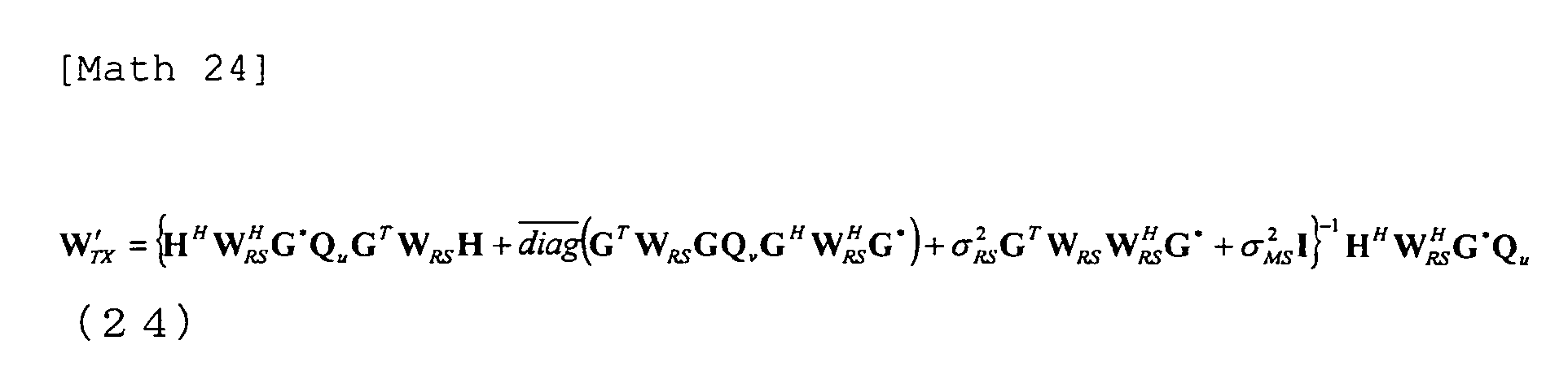
    a transmitting means for generating a transmitted signal by multiplying the received signals by a relay station transmission weight WRS and transmitting the transmitted signal to the base station and plural terminals in a second time frame.
  2. The radio communication system according to Claim 1, wherein the relay station transmission weight WRS is generated at least based on a channel between the relay station and terminals.
  3. The radio communication system according to Claim 1 or 2, wherein the signal transmitted from the base station in the first time frame is a signal that is produced by multiplying a modulated signal by a base station transmission weight WTX.
  4. The radio communication system according to Claim 3, wherein the base station transmission weight WTX is generated at least based on the channel between the base station and the relay station, or a channel between the relay station and terminals.
  5. The radio communication system according to Claim 4, wherein the relay station transmission weight WRS and the base station transmission weight WTX are generated so as to have the transmitted streams from the base station all separated and received by individual terminals.
  6. The radio communication system according to any one of Claims 3 to 5, wherein each terminal having received the signal transmitted from the relay station in the second time frame generates an interference signal based on the signal that the terminal transmitted in the first time frame and subtracts the generated interference signal from the received signal to detect the signal transmitted from the base station in the first frame.
  7. The radio communication system according to any one of Claims 3 to 6, wherein the base station having received the signal transmitted from the relay station in the second time frame generates an interference signal based on the signal that the base station transmitted in the first time frame and subtracts the generated interference signal from the received signal and multiplies the signal after subtraction of the interference signal by a reception weight WRX to detect the signal transmitted from the terminal.
  8. The radio communication system according to Claim 7, wherein the reception weight WRX is generated at least based on the channel between the base station and the relay station, or the channel between the relay station and the terminals.
  9. The radio communication system according to Claim 8, wherein the relay station transmission weight WRS, the base station transmission weight WTX and the reception weight WRX are represented as: W TX = α H - 1 G W RS = β G T - 1 G - 1 W RX = G T H T - 1 α = / tr H - 1 G H - 1 G H M β = / tr α 2 P BS / M G T - 1 G * - 1 + P MS / M G T - 1 G * - 1 + σ RS 2 G T - 1 G - 1 G H - 1 G * - 1 P RS
    Figure imgb0049

    where H is the channel matrix between the base station and the relay station, G is the channel matrix between the relay station and the plural terminals, PBS is the total transmission power of the base station, PRS is the total transmission power of the relay station, PMS is the sum of transmission powers of the terminals, the covariance matrix of the transmitted signal from base station before multiplication of the first transmission weight WTX is the unit matrix, M is the total number of antennas of the terminals, the square of σRS is the noise power at the relay station.
  10. The radio communication system according to Claim 9, wherein the relay station transmission weight WRS, the base station transmission weight WTX and the reception weight WRX are represented as: W TX = α W TX ʹ W TX ʹ = H H W RS H G * Q u G T W RS H + diag G T W RS G Q v G H W RS H G * + σ RS 2 G T W RS W RS H G * + σ MS 2 I - 1 H H W RS H G * Q u W RS = β W RS ʹ W RX = Q v G H W RS H H * H T W RS G Q v G H W RS H H * + σ RS 2 H T W RS W RS H H * + σ BS 2 I - 1 α = / tr W TX ʹ Q u W TX ʹ H P BS β = / tr W RS ʹ H W TX Q u W TX H H H W RS ʹ H + W RS ʹ G Q v G H W RS ʹ H + σ RS 2 W RS ʹ W RS ʹ H P RS vec W RS ʹ = G Q v G H T G * G T + σ RS 2 I G * G T vec G * Q v G H
    Figure imgb0050

    where H is the channel matrix between the base station and the relay station, G is the channel matrix between the relay station and the plural terminals, PBS is the total transmission power of the base station, PRS is the total transmission power of the relay station, PMS is the sum of transmission powers of the terminals, Qu is the covariance matrix of the transmitted signal from the base station before multiplication of the base station transmission weight WTX, Qv is the covariance matrix of the transmitted signal of base station, M is the total number of antennas of the terminals, the square of σBS is the noise power at the base station, the square of σRS is the noise power at the relay station and , the square of σMS is the noise power of the terminals.
  11. The radio communication system according to any one of Claims 1 to 10, wherein all the plural terminals have a same number of antennas.
  12. The radio communication system according to any one of Claims 1 to 11, wherein the plural terminals have a plurality of antennas respectively.
  13. A base station having a plurality of transmitting and receiving antennas and performing bidirectional communication with a plurality of terminals using a same frequency via a relay station having a plurality of transmitting and receiving antennas, the base station comprising:
    a transmitting means for transmitting a signal addressed to the plural terminals toward the relay station in a first time frame; and
    a receiving means for receiving a signal transmitted from the relay station in a second time frame.
  14. The base station according to Claim 13, wherein the transmitting means transmits a signal that is produced by multiplying a modulated signal by a base station transmission weight WTX.
  15. The base station according to Claim 14, wherein the base station transmission weight WTX is generated at least based on a channel between the base station and the relay station, or a channel between the relay station and the terminals.
  16. The base station according to Claim 15, wherein the base station transmission weight WTX is generated in such a manner that the transmitted streams from the base station are all separated and received by individual terminals.
  17. The base station according to Claim 15 or 16, further comprising:
    an interference signal generating means for generating an interference signal based on the signal that the base station itself transmits in the first time frame; and,
    an interference subtracting means for subtracting the generated interference signal from the signal received by the receiving means in the second time frame.
  18. The base station according to any one of Claims 15 to 17, further comprising:
    a reception weight multiplying means for multiplying the signal after subtraction of the interference signal by the interference subtracting means by a reception weight WRX; and,
    a means for detecting the transmitted signal from the terminals after multiplication of the reception weight WRX.
  19. The base station according to Claim 18, wherein the reception weight WRX is generated at least based on the channel between the base station and the relay station, or the channel between the relay station and the terminals.
  20. A relay station relaying bidirectional communication between a base station having a plurality of transmitting and receiving antennas and a plurality of terminals using a same frequency, the relay station comprising:
    a receiving means for receiving the signals transmitted from the base station and the terminals in the first time frame as received signals; and,
    a transmitting means for transmitting a signal generated by multiplying the received signals in the first time frame by a relay station transmission weight WRS as the transmitted signals in a second time frame.
  21. The relay station according to Claim 20, wherein the relay station transmission weight WRS is generated at least based on the channel between the relay station and the terminals.
  22. The relay station according to Claim 21, wherein the relay station transmission weight WRS is generated in such a manner that the transmitted streams from the base station are all separated and received by individual terminals.
  23. A terminal performing bidirectional communication with a base station having a plurality of transmitting and receiving antennas, via a relay station having a plurality of transmitting and receiving antennas using a same frequency as that of the base station and other terminals, comprising:
  24. The terminal according to Claim 23, further comprising:
    an interference signal generating means for generating an interference signal based on a signal that the terminal itself transmits in the first time frame; and,
    an interference subtracting means for subtracting the generated interference signal from the received signal in the second time frame.
EP10755900A 2009-03-27 2010-03-15 Wireless communication system, base station, relay station, and terminal Withdrawn EP2413517A1 (en)

Applications Claiming Priority (3)

Application Number Priority Date Filing Date Title
JP2009078470 2009-03-27
JP2009241048A JP5473528B2 (en) 2009-03-27 2009-10-20 Wireless communication system, base station, relay station and terminal
PCT/JP2010/054303 WO2010110102A1 (en) 2009-03-27 2010-03-15 Wireless communication system, base station, relay station, and terminal

Publications (1)

Publication Number Publication Date
EP2413517A1 true EP2413517A1 (en) 2012-02-01

Family

ID=42780794

Family Applications (1)

Application Number Title Priority Date Filing Date
EP10755900A Withdrawn EP2413517A1 (en) 2009-03-27 2010-03-15 Wireless communication system, base station, relay station, and terminal

Country Status (3)

Country Link
EP (1) EP2413517A1 (en)
JP (1) JP5473528B2 (en)
WO (1) WO2010110102A1 (en)

Cited By (3)

* Cited by examiner, † Cited by third party
Publication number Priority date Publication date Assignee Title
US9014237B2 (en) 2010-07-29 2015-04-21 Thomson Licensing Multiple-in-multiple-out network-coded amplify-and-forward relaying scheme for three node bidirectional cooperation
CN104811213A (en) * 2014-01-28 2015-07-29 华为技术有限公司 Self-interference signal removing device and method
WO2021164687A1 (en) * 2020-02-17 2021-08-26 北京紫光展锐通信技术有限公司 Relay communication method for ue and related product

Families Citing this family (7)

* Cited by examiner, † Cited by third party
Publication number Priority date Publication date Assignee Title
JP5451680B2 (en) * 2011-04-25 2014-03-26 株式会社Nttドコモ Mobile communication terminal
JP2012257190A (en) * 2011-05-16 2012-12-27 Nagoya Institute Of Technology Communication system
JP5818560B2 (en) * 2011-07-29 2015-11-18 シャープ株式会社 Wireless communication system, relay station apparatus, communication apparatus, and wireless communication method
US9124475B2 (en) * 2011-09-19 2015-09-01 Alcatel Lucent Method and apparatus for interference cancellation for antenna arrays
JP2013219664A (en) * 2012-04-11 2013-10-24 Nippon Telegr & Teleph Corp <Ntt> Radio communication system, communication device, relay device, and radio communication method
JP6459579B2 (en) * 2015-02-06 2019-01-30 株式会社デンソー Wireless communication system, base station
JP7208489B2 (en) * 2018-12-21 2023-01-19 日本電信電話株式会社 Wireless relay system and wireless relay method

Family Cites Families (1)

* Cited by examiner, † Cited by third party
Publication number Priority date Publication date Assignee Title
DE602008000755D1 (en) * 2008-01-11 2010-04-15 Ntt Docomo Inc Method, apparatus and system for channel estimation in two-way relay networks

Non-Patent Citations (1)

* Cited by examiner, † Cited by third party
Title
See references of WO2010110102A1 *

Cited By (5)

* Cited by examiner, † Cited by third party
Publication number Priority date Publication date Assignee Title
US9014237B2 (en) 2010-07-29 2015-04-21 Thomson Licensing Multiple-in-multiple-out network-coded amplify-and-forward relaying scheme for three node bidirectional cooperation
US9577722B2 (en) 2010-07-29 2017-02-21 Thomson Licensing Multiple in multiple out network coded amplify and forward relaying scheme for three node bidirectional cooperation
CN104811213A (en) * 2014-01-28 2015-07-29 华为技术有限公司 Self-interference signal removing device and method
WO2021164687A1 (en) * 2020-02-17 2021-08-26 北京紫光展锐通信技术有限公司 Relay communication method for ue and related product
US12323898B2 (en) 2020-02-17 2025-06-03 Beijing Unisoc Communications Technology Co., Ltd. Method for relay communication for user equipment and user equipment

Also Published As

Publication number Publication date
WO2010110102A1 (en) 2010-09-30
JP2010252292A (en) 2010-11-04
JP5473528B2 (en) 2014-04-16

Similar Documents

Publication Publication Date Title
EP2413517A1 (en) Wireless communication system, base station, relay station, and terminal
US8937899B2 (en) Amplify-and-forward relaying in communication systems
EP2161853B1 (en) Radio relay apparatus and method
US9231632B2 (en) Apparatus for interference cancellation in MIMO receiver, method for interference cancellation in MIMO receiver and MIMO receiver
US20120294240A1 (en) Communication system, communication device, communication method, and processor
US8989080B2 (en) Method and apparatus for cooperation in cognitive radio networks
CN101771507B (en) Method and device for eliminating intercell interference in multi-cell MIMO (Multiple Input Multiple Output) wireless communication network
Degenhardt et al. Self-interference aware MIMO filter design for non-regenerative multi-pair two-way relaying
Jaffri et al. Joint beamforming and power allocation design in cooperative MIMO-NOMA networks
US20130324136A1 (en) Communication system, base station apparatuses, and terminal devices
Santipach et al. Capacity of beamforming with limited training and feedback
US7933342B2 (en) Multipath equalization for MIMO multiuser systems
US20170230203A1 (en) Method and apparatus of topological pilot decontamination for massive mimo systems
Lee et al. Full-duplex relay based on block diagonalisation in multiple-input multiple-output relay systems
JP6441183B2 (en) Radio relay apparatus and maximum ratio combining reception method
Gesbert et al. Cooperative spatial multiplexing with hybrid channel knowledge
KR101325969B1 (en) Mobile system for signal interference cancellaion of multi input multi output networt
Unger Multiple-antenna two-hop relaying for bi-directional transmission in wireless communication systems
CN102647247B (en) One transmits preliminary treatment sending method and device
Amah et al. Multigroup multicast beamforming for multiuser two-way relaying
Zhang et al. Beamforming design for multi-user two-way relaying with MIMO amplify and forward relays
JP2011077565A (en) Radio relay system, repeater, and relay method
KR101205996B1 (en) Method for transmitting/receiving video signal in two-way relaying system
Skjevling et al. Receiver-enhanced cooperative spatial multiplexing with hybrid channel knowledge
Jebur Full duplex-transceivers: architectures and performance analysis

Legal Events

Date Code Title Description
PUAI Public reference made under article 153(3) epc to a published international application that has entered the european phase

Free format text: ORIGINAL CODE: 0009012

17P Request for examination filed

Effective date: 20111020

AK Designated contracting states

Kind code of ref document: A1

Designated state(s): AT BE BG CH CY CZ DE DK EE ES FI FR GB GR HR HU IE IS IT LI LT LU LV MC MK MT NL NO PL PT RO SE SI SK SM TR

DAX Request for extension of the european patent (deleted)
STAA Information on the status of an ep patent application or granted ep patent

Free format text: STATUS: THE APPLICATION IS DEEMED TO BE WITHDRAWN

18D Application deemed to be withdrawn

Effective date: 20131001