WO2010110102A1 - 無線通信システム、基地局、リレー局及び端末 - Google Patents
無線通信システム、基地局、リレー局及び端末 Download PDFInfo
- Publication number
- WO2010110102A1 WO2010110102A1 PCT/JP2010/054303 JP2010054303W WO2010110102A1 WO 2010110102 A1 WO2010110102 A1 WO 2010110102A1 JP 2010054303 W JP2010054303 W JP 2010054303W WO 2010110102 A1 WO2010110102 A1 WO 2010110102A1
- Authority
- WO
- WIPO (PCT)
- Prior art keywords
- base station
- signal
- relay station
- terminal
- transmission
- Prior art date
- Legal status (The legal status is an assumption and is not a legal conclusion. Google has not performed a legal analysis and makes no representation as to the accuracy of the status listed.)
- Ceased
Links
Images






Classifications
-
- H—ELECTRICITY
- H04—ELECTRIC COMMUNICATION TECHNIQUE
- H04B—TRANSMISSION
- H04B7/00—Radio transmission systems, i.e. using radiation field
- H04B7/02—Diversity systems; Multi-antenna system, i.e. transmission or reception using multiple antennas
- H04B7/022—Site diversity; Macro-diversity
- H04B7/024—Co-operative use of antennas of several sites, e.g. in co-ordinated multipoint or co-operative multiple-input multiple-output [MIMO] systems
-
- H—ELECTRICITY
- H04—ELECTRIC COMMUNICATION TECHNIQUE
- H04B—TRANSMISSION
- H04B7/00—Radio transmission systems, i.e. using radiation field
- H04B7/14—Relay systems
- H04B7/15—Active relay systems
- H04B7/155—Ground-based stations
- H04B7/15528—Control of operation parameters of a relay station to exploit the physical medium
-
- H—ELECTRICITY
- H04—ELECTRIC COMMUNICATION TECHNIQUE
- H04B—TRANSMISSION
- H04B7/00—Radio transmission systems, i.e. using radiation field
- H04B7/24—Radio transmission systems, i.e. using radiation field for communication between two or more posts
- H04B7/26—Radio transmission systems, i.e. using radiation field for communication between two or more posts at least one of which is mobile
- H04B7/2603—Arrangements for wireless physical layer control
- H04B7/2606—Arrangements for base station coverage control, e.g. by using relays in tunnels
-
- H—ELECTRICITY
- H04—ELECTRIC COMMUNICATION TECHNIQUE
- H04L—TRANSMISSION OF DIGITAL INFORMATION, e.g. TELEGRAPHIC COMMUNICATION
- H04L25/00—Baseband systems
- H04L25/02—Details ; arrangements for supplying electrical power along data transmission lines
- H04L25/03—Shaping networks in transmitter or receiver, e.g. adaptive shaping networks
- H04L25/03891—Spatial equalizers
- H04L25/03949—Spatial equalizers equalizer selection or adaptation based on feedback
-
- H—ELECTRICITY
- H04—ELECTRIC COMMUNICATION TECHNIQUE
- H04W—WIRELESS COMMUNICATION NETWORKS
- H04W84/00—Network topologies
- H04W84/02—Hierarchically pre-organised networks, e.g. paging networks, cellular networks, WLAN [Wireless Local Area Network] or WLL [Wireless Local Loop]
- H04W84/04—Large scale networks; Deep hierarchical networks
- H04W84/042—Public Land Mobile systems, e.g. cellular systems
- H04W84/047—Public Land Mobile systems, e.g. cellular systems using dedicated repeater stations
Definitions
- the present invention relates to a wireless communication system or the like in which a base station having a plurality of transmitting and receiving antennas and a terminal perform bi-directional communication via a relay station having a plurality of transmitting and receiving antennas using the same frequency.
- a relay station is one that merely amplifies and transmits a received signal (Amplify-and-Forward (AF type)), one that is demodulated and decoded once and remodulated and transmitted if there is no error (Decode-and- Forward (DF type) etc., and the base station and a terminal far away from the base station (terminal located in the vicinity of the cell edge) communicate via the relay station without deteriorating the reception characteristics of those terminals. It is possible to maintain the cell coverage as in the previous system.
- AF type An Audio-and-Forward
- DF type Decode-and- Forward
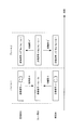
- FIG. 11 An example of a wireless communication system provided with such a relay station is shown in FIG. As shown in FIG. 11, a base station 90 and a terminal 94 are connected via a relay station 92. Here, when transmitting a signal from the base station 90 to the terminal 94, a signal of one frame is transmitted over two frames via the relay station 92.
- two-way communication method called two-way relaying or bi-directional relaying
- this method for example, as shown in FIG. 12, first, the base station 90 transmits a signal to the relay station 92, and the terminal transmits a signal to the relay station in the next frame.
- the propagation path fluctuation to which each signal is subjected is omitted.
- the relay station 92 combines the signals received in the respective frames, and broadcasts the combined signal to the base station 90 and the terminal 94 in the third frame.
- the base station 90 and the terminal 94 respectively receive signals in which two signals are mixed, and usually can not reproduce the original data.
- the base station 90 and the terminal 94 know the signal transmitted by itself, it is possible to detect the signal transmitted from the other side by subtracting the transmission signal of itself from the reception signal. it can. Thereby, two-way communication via the relay station 92, which normally requires four frames, can be realized with three frames, and frequency utilization efficiency can be improved.
- the base station 90 and the terminal 94 are configured to transmit data to the relay station 92 in different frames
- the base station 90 and the terminal 94 may be configured to simultaneously transmit data to the relay station 92.
- bi-directional communication via the relay station 92 can be realized in two frames.
- the relay station 92 can decode each signal (the base station 90 and the terminal 94 In the case of transmitting signals in different frames, or in the case where the relay station 92 has a plurality of receiving antennas although the base station 90 and the terminal 94 simultaneously transmit signals, etc.), the relay station 92 decodes the signal once and The two data may be combined and reported to the base station and terminal.
- a method is used in which a signal obtained by XORing two data transmitted from base station 90 and terminal 94 is modulated and broadcasted to each.
- Non-Patent Document 1 discloses a method of applying this two-way relaying (Bi-directional relaying) to Multiple-Input Multiple-Output (MIMO) communication.
- Non-Patent Document 1 a case is considered where a base station, a relay station, and a terminal each have two antennas, and two streams of data (different data for each antenna) are transmitted from the base station and the terminal. There is.
- a relay station transmits a signal to a base station and a terminal, the signal is multiplied by the transmission weight, and the base station and the terminal that received this signal have known interference (A configuration is shown in which the signal after subtraction of the signal transmitted by itself is multiplied by the reception weight (FIG. 13).
- the base station and the terminal know the two signals transmitted by themselves (the base station recognizes u 1 and u 2 , and the terminal v 1 and v 2 ). Can be subtracted from the received signal. Also, after subtracting the self interference (known interference transmitted by itself) from the received signal, the signal has two desired signals (v 1 and v 2 for the base station, u 1 and u 2 for the terminal) and noise And the same processing as normal MIMO (here, signal separation by multiplying reception weights) can be performed. By multiplying such transmission / reception weights, it becomes possible to perform signal detection in the base station and terminal with good characteristics, and bi-directional communication can be realized efficiently.
- Non-Patent Document 2 shows a method of applying two-way relaying (Bi-directional relaying) to multi-user MIMO (MU-MIMO) communication in which a base station simultaneously communicates with a plurality of terminals. ing.
- Bi-directional relaying two-way relaying
- MU-MIMO multi-user MIMO
- the signal addressed to the base station from the terminal A is transmitted to the relay station.
- the signal transmitted from the terminal A to the relay station is also received and demodulated at the terminal B, and this demodulated signal is later used as a known interference signal.
- the signal addressed to the terminal B is transmitted from the base station to the relay station.
- the signal addressed to the base station from the terminal B is transmitted to the relay station.
- the signal transmitted from the terminal B to the relay station is also received and demodulated at the terminal A, and this demodulated signal is later used as a known interference signal.
- the relay station demodulates, decodes and remodulates the signals received from the base station and the two terminals, and synthesizes the synthesized signal to the base station and the two terminals.
- the base station and the two terminals that have received this signal need to subtract the signal that is interfering to detect the required signal respectively, but the base station transmits the signal addressed to the two terminals that it has transmitted. Since this is grasped, this subtraction can be performed and the desired signal can be extracted.
- Non-Patent Document 2 interference signals (signals transmitted by other terminals) to be subtracted can be grasped in each terminal even in the MU-MIMO environment, but other terminals While transmitting a signal to a relay station, processing for receiving and demodulating the signal is required, and it is difficult to realize when the distance between terminals is long. Also, this process is not preferable from the viewpoint of the power consumption of the terminal and the privacy of the transmission data of the terminal. Furthermore, although the method disclosed in Non-Patent Document 2 requires three time resources, it is desirable to realize a highly efficient system in which the necessary resources are further reduced.
- an object of the present invention is to achieve efficiency with few resources when performing MU-MIMO bi-directional communication between a base station equipped with multiple antennas and multiple terminals via relay stations. It is to provide a communication system etc. which realize well.
- a base station provided with a plurality of transmitting and receiving antennas and a plurality of terminals use the same frequency and are bi-directional via a relay station provided with a plurality of transmitting and receiving antennas.
- a wireless communication system for performing communication wherein a base station and a plurality of terminals simultaneously transmit signals to a relay station in a first time frame, and the relay station transmits the signals transmitted in the first time frame.
- Receiving means for receiving as a reception signal the reception signal is multiplied by the relay station transmission weight W RS to generate a transmission signal, and the transmission signal is transmitted to the base station and a plurality of terminals in a second time frame And means.
- the relay station transmission weight W RS is generated based on at least a propagation path between the relay station and a terminal.
- the signal transmitted from the base station in the first time frame is a signal obtained by multiplying the base station transmission weight W TX by the modulation signal.
- the base station transmission weight W TX is generated based on at least a propagation path between the base station and the relay station or a propagation path between the relay station and the terminal. It is characterized by
- the relay station transmission weight W RS and the base station transmission weight W TX are generated such that the transmission stream of the base station is all separated and received by each terminal. It is characterized by being.
- the terminal having received the signal transmitted from the relay station in the second time frame is configured to receive an interference signal based on the signal transmitted by itself in the first time frame.
- a signal transmitted from the base station in the first frame is detected by generating and subtracting the generated interference signal from the reception signal.
- the base station having received the signal transmitted from the relay station in the second time frame detects an interference signal based on the signal transmitted by itself in the first time frame.
- a signal transmitted from the terminal is detected by generating and subtracting the generated interference signal from the reception signal, and multiplying the signal after subtraction of the interference signal by the reception weight W RX .
- the reception weight W RX is generated at least based on a propagation path between the base station and the relay station or a propagation path between the relay station and the terminal. It features.
- the relay station transmission weight W RS , the base station transmission weight W TX , and the reception weight W RX represent a propagation path matrix between the base station and the relay station H, the relay station And a channel matrix between a plurality of terminals G, a total transmission power of the base station P BS , a total transmission power of the relay stations P RS , a total of the transmission powers of the terminals P MS , the first transmission weight W
- the covariance matrix of the transmission signal of the base station before multiplication by TX is a unit matrix
- the sum of the number of antennas of the terminal is M
- the noise power of the relay station is a square of ⁇ RS , Equation (3) (5) (6) (8) (9).
- the relay station transmission weight W RS , the base station transmission weight W TX , and the reception weight W RX represent a propagation path matrix between the base station and the relay station H, the relay station And a channel matrix between a plurality of terminals G, a total transmission power of a base station P BS , a total transmission power of relay stations P RS , a total of transmission powers of terminals P MS , the base station transmission weight W TX
- the noise power of the relay station is taken as the square of ⁇ RS and the noise power of the terminal is taken as the square of ⁇ MS , they are characterized by Expressions (23) to (29).
- the plurality of terminals all have the same number of antennas.
- each of the plurality of terminals comprises a plurality of antennas.
- the wireless communication base station is a base station that performs bidirectional communication using the same frequency as a plurality of terminals via a relay station including a plurality of transmitting and receiving antennas and a plurality of transmitting and receiving antennas. Providing transmitting means for transmitting signals addressed to the plurality of terminals toward the relay station in a first time frame, and receiving means for receiving signals transmitted from the relay station in a second time frame. It features.
- the transmission means transmits a signal obtained by multiplying the base station transmission weight W TX by the modulation signal.
- the base station transmission weight W TX is generated based on at least a propagation path between the base station and the relay station or a propagation path between the relay station and the terminal. Do.
- the base station transmission weight W TX is generated so that all transmission streams of the base station are separated and received by each terminal.
- the base station comprises interference signal generation means for generating an interference signal based on a signal transmitted by itself in the first time frame, and a signal in the second time frame received by the reception means. And D. interference subtraction means for subtracting the generated interference signal from.
- reception weight multiplying means for multiplying the signal after interference signal subtraction by the interference subtraction means by the reception weight W RX , and the signal transmitted from the terminal after multiplication by the reception weight W RX And means for detecting.
- the reception weight W RX is generated based at least on a propagation path between the base station and the relay station or a propagation path between the relay station and the terminal.
- the relay station is a relay station that relays two-way communication between a base station equipped with a plurality of transmitting and receiving antennas and a plurality of terminals using the same frequency, A receiving unit that receives signals transmitted from the base station and the terminal in one time frame as reception signals; and a reception signal in the first time frame multiplied by a relay station transmission weight W RS . And transmitting means for transmitting the signal as a transmission signal in a second time frame.
- the relay station transmission weight W RS is generated based on at least a propagation path between the relay station and a terminal.
- the base station transmission weight W RS is generated such that all transmission streams of the base station are separated and received by each terminal.
- a terminal performs bi-directional communication with the base station via a relay station provided with a plurality of transmission / reception antennas using the same frequency as a base station provided with a plurality of transmission / reception antennas and other terminals. And transmitting means for transmitting a signal addressed to the base station to the relay station in a first time frame, and receiving means for receiving a signal transmitted from the relay station in a second time frame. It is characterized by
- the terminal of the present invention generates interference signal generation means for generating an interference signal based on the signal transmitted by itself in the first time frame, and subtracts the generated interference signal from the reception signal in the second time frame. And subtracting means.
- MU-MIMO bi-directional communication between a base station and a terminal provided with a plurality of antennas can be efficiently realized with a small number of resources (2 frames), when performing via a relay station. it can.
- each terminal receives a signal in which unknown interference is mixed by multiplying the transmission signal with a weight suitable for bi-directional communication in a MU-MIMO environment by the base station and relay station and transmitting the result. Control can be done to avoid this.
- each terminal can receive a composite signal of only the desired signal and known interference, and can detect the desired signal efficiently by subtracting known interference.
- the known interference signal can be subtracted on the side of the base station, and good reception characteristics can be obtained by multiplying the reception weight.
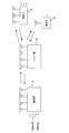
- FIG. 1 is a diagram for explaining the outline of the wireless communication system 1.
- terminals 30 terminal A and terminal B are connected to the wireless communication system 1 via a base station 10 and a relay station 20.
- the present invention relates to a method for efficiently realizing MU-MIMO bi-directional communication between a base station provided with a plurality of antennas and a plurality of terminals via a relay station with a small number of resources.
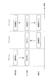
- the base station 10 and the terminals 30 respectively transmit signals to the relay station 20 in the first time frame, and in the second time frame A signal is broadcast from the relay station 20 to the base station 10 and the two terminals 30.
- the base station 10 and the relay station 20 multiply the transmission signal by weights (W TX and W RS ) suitable for bi-directional communication in the MU-MIMO environment, respectively, to obtain a signal in which unknown interference is mixed. Control is performed so that each terminal does not receive. By this weight multiplication control, each terminal can receive a composite signal of only the desired signal and known interference, and can detect the desired signal efficiently by subtracting known interference.
- u 1 is obtained by interference subtraction
- u 2 is obtained by interference subtraction.
- maximum likelihood detection can be performed on a signal after known interference subtraction, and transmission and reception can also be performed by multiplying the signal by a weight.
- the base station side can perform subtraction of known interference signals, and further, by multiplying the reception weight (W RX ), the signal transmitted from the terminal can be detected. That is, in the frame 2, in the base station 10, when W RX is multiplied after interference subtraction, v 1 and v 2 are obtained.
- the base station 10 can also perform maximum likelihood detection on a signal after known interference subtraction, and can obtain good reception characteristics.
- MU-MIMO Two-way relaying in the case of using transmission and reception weights based on the concept of ZF (Zero Forcing) that compensates the received signal as it is (to match the transmitted signal) will be described.
- ZF Zero Forcing
- the propagation path fluctuation received when a signal is transmitted from the antenna 1 of the base station 10 to the antenna 1 of the relay station 20 is h 11
- the propagation path fluctuation of the antenna 1 of the base station 10 to the antenna 2 of the relay station 20 Is h 21
- the propagation path fluctuation of the antenna 2 of the base station 10 to the antenna 1 of the relay station 20 is h 12
- the propagation path fluctuation of the antenna 2 of the base station 10 to the antenna 2 of the relay station 20 is h 22 .
- the propagation path fluctuation received when a signal is transmitted from the antenna of the terminal A to the antenna 1 of the relay station 20 is g 11
- the propagation path fluctuation of the antenna 2 of the terminal A to the antenna 2 of the relay station 20 is g 21
- the propagation path fluctuation of the antenna 1 of the relay station 20 is g 12 from the above antenna
- the propagation path fluctuation of the antenna 2 of the relay station 20 from the antenna of the terminal B is g 22 .
- the propagation path fluctuation between the base station 10 and the relay station 20, and between the terminal 30 and the relay station 20 is represented by a matrix such as H or G, it is suitable for MU-MIMO Two-way relaying according to the present invention.
- the weights (W TX , W RS , W RX ) are expressed as follows.
- ⁇ is a coefficient that normalizes the transmission power of the base station, and is expressed by the following equation.
- the total transmission power of the base station is P BS
- the covariance matrix of the signal (before multiplication by W TX ) transmitted from the base station is Q u
- tr (X) is a trace of the matrix X (pair Represents the sum of corner components).
- M represents the number of antennas (number of terminals), which is “2” here.
- I is a unit matrix.
- ⁇ is a coefficient that normalizes the transmission power of the relay station, and is expressed by the following equation.
- the total transmission power of the relay station is P RS
- the covariance matrix of the signals transmitted from the two terminals is Q v
- the noise power at the relay station is the square of ⁇ RS .
- G * represents the complex conjugate matrix of the matrix G.
- the reception weight in a base station is represented as follows.
- the received signals at the base station 10 and the two terminals 30 in the case of using the transmission and reception weights as shown in the equations (3) to (9) above are shown below.
- the transmission signal for the terminal A from the base station 10 is u 1
- the transmission signal for the terminal B from the base station is u 2
- the transmission signal for the terminal A is v 1
- the transmission signal for the terminal B is v 2 .
- the noise component is omitted to simplify the explanation.
- the signal y RS received by the relay station in the first frame of FIG. 2 is expressed as follows.
- the signal x RS transmitted by the relay station in the second frame is expressed as follows.
- the signal represented by this equation (13) is received by the terminal via the propagation path as follows.
- terminal A receives a composite signal of u 1 of the desired signal and known interference signal v 1 transmitted by itself, and the unknown interference signal is mixed. I did not. Therefore, the desired signal u 1 can be extracted by subtracting the known interference signal v 1 multiplied by the transmission power normalization coefficient ⁇ from the received signal.
- a composite signal of u 2 of the desired signal and the known interference signal v 2 transmitted by itself is received, and since the unknown interference signal is not mixed, the known interference signal v from the received signal is
- the desired signal u 2 can be extracted by subtracting 2 multiplied by the transmission power normalization coefficient ⁇ .
- the relay station 20 needs to notify in advance each terminal 30 of the transmission power normalization coefficient ⁇ .
- unknown interference is caused by multiplying the transmission signal at the base station by the transmission weight represented by equation (3) and multiplying the transmission signal at the relay station 20 by the weight represented by equation (6).
- Control can be performed such that each terminal does not receive mixed signals. That is, each terminal 30 can receive a combined signal of only the desired signal and known interference, and can detect the desired signal efficiently by subtracting the known interference.
- the signal represented by equation (11) is received as a signal y BS at the base station as follows.
- the base station recognizes both u 1 and u 2 and can subtract it from the received signal as an interference component. Subtraction of the interference component from equation (15) results in:
- the interference component is first subtracted from the reception signal of equation (15) and then the reception weight of equation (9) is multiplied, conversely, the interference component is subtracted after multiplication by the reception weight. Can also extract the desired signal.
- the reception weight at this time may be the same as that of equation (9).
- the base station 10 and the relay station 20 By multiplying the transmission weight according to the present embodiment by the base station 10 and the relay station 20, it is possible to control each terminal 30 not to receive a signal in which unknown interference is mixed.
- MU-MIMO Two-way relaying can be efficiently realized by performing subtraction on known interference signals.
- the desired signal can be obtained by subtracting the interference signal and multiplying the reception weight.
- MLD Maximum Likelihood Detection
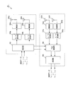
- the transmission unit 100 of the base station 10 in this embodiment includes a modulation unit 102, a transmission weight multiplication unit 104, D / A conversion units 106 (106a and 106b), and a radio unit 108 (108a). And 108b), and a transmitting antenna unit 110 (110a and 110b) (transmitting antennas 1 and 2).
- the receiving unit 150 includes receiving antenna units 152 (152a and 152b) (receiving antennas 1 and 2), wireless units 154 (154a and 154b), A / D converting units 156 (156a and 156b), and interference subtraction. And a reception weight multiplication unit 160, and a demodulation unit 162.
- transmitting section 100 first, modulation of two transmission data (destined to terminal A and addressed to terminal B) is performed in modulating section 102, and the modulated signal is represented by formula (3) in transmitting weight multiplying section 104. Transmission weight multiplication is performed. However, it is assumed that all propagation paths are grasped in advance in the base station 10 by feedback from the relay station 20 or the like.
- the two signals after transmission weight multiplication in the transmission weight multiplication unit 104 are respectively input to the D / A conversion unit 106, and are converted from digital signals to analog signals. Then, after being frequency-converted to a frequency band in which wireless transmission is possible in the wireless unit 108, the signal is transmitted from the transmitting antenna unit 110.
- the signal transmitted from the relay station 20 is first received by the receiving antenna unit 152, converted to a frequency that can be A / D converted by the wireless unit 154, and then received by the A / D conversion unit 156.
- An analog signal is converted to a digital signal.
- interference subtraction is performed in the interference subtraction unit 158
- its own transmission signal is input from the modulation unit 102 to the interference subtraction unit 158 and used as a known interference signal.
- a propagation path by which a known interference signal is multiplied is also grasped, and the propagation path, its own transmission signal, and a signal multiplied by a coefficient such as ⁇ and ⁇ are subtracted as interference.
- the signal after the interference subtraction is input to the reception weight multiplication unit 160, and after multiplication of the reception weight represented by equation (7) is performed, the signal is demodulated by the demodulation unit 162, transmitted from the terminal, and transmitted via the relay station. The incoming data is reproduced.
- the base station 10 With such a configuration of the base station 10, it is possible to transmit a signal multiplied by a transmission weight suitable for MU-MIMO Two-way relaying, and to transmit its own transmission signal as an interference signal from the reception signal.
- a desired signal can be efficiently obtained by subtraction and multiplication by the reception weight.
- reception weight multiplication may not be performed, and maximum likelihood detection may be performed on a signal after known interference subtraction.
- the present embodiment is not configured to simultaneously perform transmission and reception, so two antennas in total are provided and a changeover switch is provided. Can also be configured to switch between transmission and reception.
- the number of transmitting antennas and the number of receiving antennas may be three or more.
- the relay station 20 in the present embodiment includes a receiving antenna unit 200 (200a and 200b), radio units 202 (202a and 202b) and 210 (210a and 210b), and an A / D conversion unit 204. (204a and 204b), weight multiplication unit 206, D / A conversion unit 208 (208a and 208b), and transmission antenna unit 212 (212a and 212b).
- the signals transmitted from the base station 10 and the two terminals 30 are received by the receiving antenna unit 200 of the relay station 20 and frequency-converted from the radio frequency to a frequency that can be A / D converted by the radio unit 202.
- this signal is converted from an analog signal to a digital signal in the A / D conversion unit 204, and then multiplied by the weight represented by equation (6) in the weight multiplication unit 206.
- the transmitting antenna unit 212 After being converted from a digital signal to an analog signal in the D / A conversion unit 208 and frequency-converted to a frequency that can be wirelessly transmitted in the wireless unit 210, it is transmitted from the transmitting antenna unit 212 toward the base station 10 or the terminal 30. .
- the base station 10 receives signals transmitted from the base station 10 and the terminal 30, multiplies the received signal by a weight suitable for MU-MIMO Two-way relaying, and And the terminal 30 can be transmitted again, and the terminal 30 can be controlled so as not to receive a signal in which unknown interference is mixed.
- the present embodiment is not configured to simultaneously perform transmission and reception, so two antennas in total are provided and a changeover switch is provided. Can also be configured to switch between transmission and reception. Further, as long as the number of terminals (the number of streams) simultaneously performing MU-MIMO communication is the same, the number of transmitting antennas and the number of receiving antennas may be three or more.
- the device configuration of the terminal 30 in the present embodiment is shown in FIG.
- the terminals 30 terminals A and B in the present embodiment
- the transmission unit 300 of the terminal 30 in the present embodiment is configured to include a modulation unit 302, a D / A conversion unit 304, a radio unit 306, and a transmission antenna unit 308.
- the receiving unit 350 is configured to include a receiving antenna unit 352, a wireless unit 354, an A / D conversion unit 356, an interference subtraction unit 358, and a demodulation unit 360.
- transmission data is modulated by the modulation unit 302, and the D / A conversion unit 304 converts a digital signal into an analog signal. Then, after being frequency-converted to a frequency that can be wirelessly transmitted by the wireless unit 306, the frequency is transmitted from the transmitting antenna unit 308.
- the signal received by the reception antenna unit 352 is frequency-converted to a frequency that can be A / D converted in the wireless unit 354, and converted from an analog signal to a digital signal in the A / D conversion unit 356. Then, interference subtraction is performed in the interference subtraction unit 358, and the transmission signal of its own is input from the modulation unit 302 to the interference subtraction unit 358 and used as a known interference signal.
- a signal obtained by multiplying this own transmission signal and the coefficient ⁇ notified in advance from the relay station 20 is subtracted from the reception signal as an interference signal.
- the signal from which the interference signal has been subtracted in this way is demodulated by the demodulation unit 360, and the data transmitted from the base station 10 and arriving via the relay station 20 is regenerated.
- the signal transmitted by itself can be subtracted from the received signal as an interference signal, and the desired signal can be detected.
- one transmitting antenna and one receiving antenna are provided.
- the switch may be configured to switch between transmission and reception.
- the base station 10 and relay station 20 can multiply the weight according to the present embodiment by the signal, and unknown interference is mixed. It is possible to control so that each terminal does not need to receive the received signal. Then, the base station 10 and the terminal 30 perform subtraction on known interference signals to relay the number of antennas necessary for decoding the signal received in frame 1 (signals transmitted from the base station and the terminal). Even in the case where S.N. is not provided, MU-MIMO Two-way relaying can be efficiently realized with a small number of resources (2 frames).
- the frequency used for transmission of the first time frame and the second time frame is assumed to be the same, but in a system provided with a plurality of frequency channels, the first one is used. Different frequency channels may be used in the time frame and the second time frame.
- the transmit and receive weights in this embodiment are expressed as follows.
- each terminal does not have to receive a signal in which unknown interference is mixed. It becomes possible to control and MU-MIMO Two-way relaying can be realized efficiently.
- each device configuration is realized by adding a frequency channel switching unit that switches the frequency channel used in the first time frame and the second time frame to the configuration shown in this embodiment. Can.
- the base station and the relay station grasp all propagation path fluctuations in advance.
- the base station can not directly know the propagation path fluctuation between the relay station and the terminal, in order to grasp all the propagation path fluctuations, the propagation path fluctuation between the relay station and the terminal is notified to the base station There is a need.
- the relay station since the signals transmitted from the base station and each terminal can be directly received, it is possible to directly know the propagation path to the base station and the propagation path to the terminal. . Therefore, the transmission and reception weights (or only transmission weights) may be calculated using each channel matrix estimated in the relay station, and the calculated result may be notified from the relay station to the base station. With such a configuration, it is not necessary to calculate weights separately in the base station and the relay station, and the procedure can be simplified.
- Second Embodiment In the first embodiment, MU-MIMO Two-way relaying in the case of using transmission and reception weights based on the concept of ZF (Zero Forcing) is described, but in this case, in order to compensate the signal as it is.
- the noise component may be emphasized. So, in 2nd Embodiment to which this invention is applied, it shows about the transmission-and-reception weight which also considered the influence of the noise component.
- W TX is expressed as follows.
- I a coefficient that normalizes the transmission power of the base station, and is expressed by the following equation. Further, the square of ⁇ MS is the noise power of the terminal, and the second term on the right side of equation (24) represents a matrix composed only of non-diagonal components of the matrix in ().
- W RS is expressed as follows.
- vec () is a vector representation of the matrix in (), and the first term and the second term on the right side of equation (27) represent the Kronecker product.
- ⁇ is a coefficient that normalizes the transmission power of the relay station, and is expressed by the following equation.
- W RX is expressed as follows. However, the square of ⁇ BS is the noise power of the base station.
- the base station 10, the relay station 20, and the terminal 30 in the present embodiment can be realized with the same configuration as that shown in the first embodiment. However, it is assumed that weights used in each weight multiplication unit and coefficients such as ⁇ and ⁇ are as shown in this embodiment.
- the number of receiving antennas of the base station 10 and the relay station 20 is two and the number of terminals is two, and each terminal is provided with one antenna. Even in the case of the number of terminals, the present invention is applicable by using a channel matrix corresponding to the situation.
- the channel matrix which is 2 ⁇ 2 in the above embodiment is 4 ⁇ 4.
- the transmission signal vector that was 2 ⁇ 1 corresponds to 4 ⁇ 1, and by performing such correspondence, using the weights shown so far as in the case of 2 ⁇ 2 it can.
- the weights shown in the above embodiments are the same as described above.
- MU-MIMO Two-way relaying can be realized using this.
- the present invention can be applied to the case where there are two terminals of the base station 10 and the relay station 20 with four receiving antennas each and a terminal having three antennas and a terminal having one antenna. is there.
- weights are weights for enabling each stream (modulated signal before multiplication by W TX ) transmitted from the base station to be separated and received at the terminal side, as shown in FIG.
- W TX modulated signal before multiplication by W TX
- the terminal has a plurality of antennas, it is not necessary to use a weight that separates all streams, and it may be a weight that does not cause unknown interference for the terminal.
- the interference signals for terminal A shown in FIG. 6 are u 3 , u 4 , v 3 and v 4 , and these signals need not be mixed with the received signal of terminal A, but u 1 and u 2 are desired signals, and v 1 and v 2 are all known interferences. Therefore, it is not necessary to separate these signals (u 1 , u 2 , v 1 , v 2 ) by weight control of the base station and the relay station, and the terminal receives a signal in which these signals are mixed (added) Alternatively, they may be separated by processing at the terminal to detect a desired signal.
- weight control when a terminal is provided with a plurality of antennas, weight control will be described such that the terminal does not receive unknown interference without completely separating each stream.
- weights used in the relay station are present. It shows about the weight used in a base station when it shall be shown in 1st Embodiment.
- the weight of the relay station in the first embodiment is expressed by the following equation (30).
- ⁇ is a coefficient for normalizing the transmission power in the relay station, which is expressed by equation (28), and in this embodiment, each channel matrix (H, G) is a 4 ⁇ 4 matrix.
- the received signal vector at the terminal when this weight is used is expressed as follows from equation (14).
- ⁇ is a coefficient that normalizes the transmission power at the base station, represented by equation (25).
- Equation (30) when using the weight shown in Equation (30) in the relay station, the signals (streams) transmitted from the two terminals are completely separated and the respective terminals are separated.
- the unknown interference transmitted from another terminal is not mixed in the received signal. Therefore, a known interference component can be removed by subtracting the result of multiplication of ⁇ by its own transmission signal at each terminal from the reception signal.
- Equation (31) represents the desired signal component transmitted from the base station to the terminal, but the signal addressed to another terminal is unknown (for example, the signal for terminal A is for terminal B)
- the signal addressed to another terminal is unknown (for example, the signal for terminal A is for terminal B)
- F 1 and F 2 are both 2 ⁇ 4 matrices
- F 1 is a propagation path through which a signal received by terminal A passes
- F 2 is a propagation through which a signal received by terminal B The road is shown respectively.
- singular value decomposition is performed on F 1 and F 2 constituting such a propagation path F, respectively.
- Singular value decomposition is an m ⁇ n matrix J, an m ⁇ m unitary matrix S, an element other than diagonal elements is 0, and diagonal elements are singular values of the matrix J.
- the transmission weight of the base station that can be converted can be expressed as follows.
- the signal received at terminal A is a signal in which u 1 and u 2 are combined, and u 3 and u 4 are not mixed.
- the signal received at the terminal B, and a composite signal u 3 and u 4, u 1 and u 2 are not mixed. That is, by transmitting a signal obtained by multiplying the transmission weight subjected to block diagonalization by the base station, a signal (a signal not separated for each stream) in which the desired signal for each terminal is mixed is received, and the base station Can be controlled so that it does not receive unknown interference transmitted to another terminal.
- Each terminal performs maximum likelihood detection etc. on the synthesized signal of the desired signal remaining after subtracting the known interference signal (the second term on the right side of equation (31)) from the received signal, and the desired signal (stream) You can separate the Compared to the first and second embodiments in which each desired signal (stream) is all separated by multiplying linear weights and received at the terminals, in this embodiment, streams for different terminals are separated by linear weights.
- streams for different terminals are separated by linear weights.
- multiple streams for one terminal are not separated, there is a high possibility that good reception characteristics can be obtained in a situation where separation by linear processing is not suitable, such as when there is correlation between antennas.
- the relay station multiplies the same weight as that of the first embodiment, the signal after the known interference subtraction becomes the same signal as that of the first embodiment. Therefore, it is possible to detect the desired signal by multiplying the same reception weight as that of the first embodiment, and to perform maximum likelihood detection.
- FIG. 7 an apparatus configuration of the base station 10 in the present embodiment is shown in FIG.
- the base station 10 in the present embodiment has a configuration in which the number of antennas of the device shown in FIG. 3 is increased, and the same reference numerals as in FIG. 3 are attached.
- multiplication of the reception weight is not performed, and the demodulation unit 162 is configured to perform maximum likelihood detection of the desired signal.
- the transmission weight multiplication unit 104 multiplies the transmission weight to which the above block diagonalization is applied.
- the relay station 20 in the present embodiment has a configuration in which the number of antennas of the device shown in FIG. 4 is increased, and the same reference numerals as in FIG. 4 are attached.
- the weight to be multiplied by the weight multiplication unit 206 can be expressed by the same equation as the weight shown in the first embodiment.
- the terminal 30 in this embodiment has a configuration in which the number of antennas of the device shown in FIG. 5 is increased, and the same reference numerals as in FIG. 5 are attached.
- the terminal receives unknown interference without completely separating the desired signal for each stream by transmitting the signal multiplied by the transmission weight subjected to block diagonalization as described above with the above-described apparatus configuration. It can control so that it does not need.
- the base station uses the weight calculated by block diagonalization, and the relay station uses the weight based on the concept of ZF. However, as in the base station, the relay station also uses block pairs. Signal transmission can be performed using weights calculated using cornification. In the fourth embodiment, a case where weights calculated using block diagonalization are also used in the relay station will be described.
- the received signal at the terminal in the case of performing MU-MIMO Two-way Relaying according to the present invention is expressed as follows. However, for the sake of simplicity, the noise component is ignored.
- the second term of this equation (40) represents the signal transmitted from the relay station in frame 2 by multiplying the weight in the relay station by the signal transmitted from each terminal in frame 1 and received by the relay station. This is a term including known interference transmitted by itself and unknown interference transmitted from another terminal.
- WRS is calculated using block diagonalization in this embodiment, here, the second term of equation (40) is rewritten as follows.
- ⁇ is a coefficient which is represented by equation (28) and which normalizes the transmission power at the relay station.
- the second term of the equation (40) is rewritten so that the relay station weight W RS is represented by the product of W ′ RS1 and W ′ RS2 .
- W 'RS1 is a matrix for performing block diagonalization is regarded as a virtual channel F to G T that is multiplied on the left side in the third embodiment
- W' RS2 is multiplied to the right
- It is a matrix for performing block diagonalization by regarding G as a virtual propagation path F in the third embodiment.
- 'it becomes RS1 is Block Diagonalization as shown in equation (38) matrix
- W' G T W RS2 G also becomes similarly block diagonalized matrix.
- G 1 and G 2 are both 4 ⁇ 2 matrices.
- the results are as follows.
- W ′ RS2 is obtained as follows.
- W ' RS2 is obtained by such a procedure, and together with W' RS1 , the virtual channel matrix transmitted by each terminal in frame 1 and transmitted from the relay station in frame 2 is block diagonalized via frame 2 It is possible to control so that each terminal does not receive unknown interference transmitted from another terminal without separating the known signal (interference) transmitted by itself in each stream. . Then, in the terminal, it is possible to subtract known interference by grasping the submatrix included in its own received signal among the block diagonalized matrix.
- a desired signal in a terminal that receives a block diagonalized signal, can be detected by performing maximum likelihood detection, multiplication of reception weights, and the like after known interference subtraction. Also in the base station, the desired signal can be detected by performing maximum likelihood detection, multiplication of the reception weight, and the like after known interference subtraction as in the embodiments described above.
- control such that all streams are separated and received is similarly applicable to the case shown in FIG.
- the present invention is also applicable to weight control using block diagonalization as described in the third and fourth embodiments.
- terminal A and terminal B have different numbers of desired signals (streams) and interferences (streams), it is necessary to perform block diagonalization in consideration of this.
- F 1 constituting the virtual channel matrix of equation (32) is a 3 ⁇ 4 matrix
- F 2 is a 1 ⁇ 4 matrix. It is necessary to do In this case, as in the third embodiment, F 1 is a channel through which the signals received at the terminal A, F 2 indicates the channel through which the signal received at the terminal B, respectively.
- F 1 and F 2 are subjected to singular value decomposition as in the third embodiment, they can be expressed as follows.
- the transmission weight of the base station capable of block diagonalizing the virtual propagation path F is expressed as follows.
- weight control using block diagonalization in the relay station as in the fourth embodiment can be applied similarly, and different numbers as shown in FIG. It is possible to realize MU-MIMO Two-way Relaying in the case where there are multiple terminals equipped with the following antennas.
- a device provided with a plurality of antennas performing two-way communication with two terminals is referred to as a base station, and a device provided with a plurality of antennas for relaying the two-way communication between the base station and the terminals with a relay station
- the present invention is applicable to a system in which a terminal provided with a plurality of antennas performs two-way communication with a plurality of terminals, and the base station is not a relay station that specializes in relaying, and is usually a base station.
- a device that operates as a relay station may play the role of a relay station.
- the present invention is also applicable to a configuration in which a terminal provided with a plurality of antennas operates as a relay station.
- optimization criteria highest transmission rate or minimum MSE (Mean Square Error), etc.
- Formula of each weight corresponding to the reference is calculated. Since the base station transmission weight and the relay station transmission weight obtained in this way are mutually associated, it is not possible to obtain an optimum value by one operation, and optimization must be made by iterative operation. .
- one of the weights is initialized, and another weight is calculated using the initialized weight. Then, using the calculated weights, the processing of updating the value of the other weight (the weight initialized earlier) is repeated until the values of the two weights converge. The finally obtained value can be said to be the optimum weight in each optimization criterion.
- the base station transmission weight and the relay station transmission weight according to the present invention can also be determined by such an iterative process.
- 1 wireless communication system 10 base station 100 transmission unit 102 modulation unit 104 transmission weight multiplication unit 106, 106a, 106b D / A conversion unit 108, 108a, 108b radio unit 110, 110a, 110b transmission antenna unit 150 reception unit 152, 152a, 152b Reception antenna unit 154, 154a, 154b Radio unit 156, 156a, 156b A / D conversion unit 158 Interference subtraction unit 160 Reception weight multiplication unit 162 Demodulation unit 20 Relay station 200, 200a, 200b Reception antenna unit 202, 202a, 202b Radio Section 204, 204a, 204b A / D conversion section 206 Weight multiplication section 208, 208a, 208b D / A conversion section 210, 210a, 210b Radio section 212, 212a, 212b Transmit antenna section 3 Terminal 300 transmitting unit 302 modulating unit 304 D / A conversion unit 306 radio unit 308 transmitting antenna unit 350 receiving unit 352 receiving antenna unit 3
Landscapes
- Engineering & Computer Science (AREA)
- Computer Networks & Wireless Communication (AREA)
- Signal Processing (AREA)
- Physics & Mathematics (AREA)
- Mathematical Physics (AREA)
- Power Engineering (AREA)
- Mobile Radio Communication Systems (AREA)
- Radio Relay Systems (AREA)
- Radio Transmission System (AREA)
Abstract
複数の送受信アンテナを備えた基地局と複数の端末が同じ周波数を用いて、複数の送受信アンテナを備えたリレー局を介して双方向の通信を行う無線通信システムであって、第一の時間フレームにおいて基地局と端末が同時にリレー局へ信号を送信し、前記第一の時間フレームにおいて送信された信号を受信したリレー局は、前記受信信号にリレー局送信ウェイトを乗算して生成された信号を第二の時間フレームにおいて基地局と複数の端末へ送信する。これにより、複数アンテナを備えた基地局と複数の端末の間のMU-MIMO双方向通信を、リレー局を介して行う場合に、少ないリソースで効率良く実現する通信システム等を提供することができる。
Description
本発明は、複数の送受信アンテナを備えた基地局と端末とが同じ周波数を用いて、複数の送受信アンテナを備えたリレー局を介して双方向の通信を行う無線通信システム等に関する。
近年のデータ通信量の増加に伴う周波数資源の逼迫を解決するために、新たな無線周波数を移動体通信用として割り当て、割り当てられた周波数帯域を使用する新たな移動体通信システムの構築(例えば、IMT-Advancedシステム)が進められている。このような新たな移動体通信システム用としては、これまでのシステムに割り当てられていた周波数帯に比べて高い周波数帯が割り当てられることとなるが、より高い周波数の信号はより大きく減衰することから、これまでのシステムに比べてカバレッジが狭くなってしまう。このような問題を解決する手段として、基地局-端末間の通信を中継するリレー局をセル内に設ける方法がある。
リレー局には、受信した信号を増幅して送信するだけのもの(Amplify-and‐Forward:AFタイプ)や、一旦復調、復号し誤りがなければ再変調して送信するもの(Decode‐and‐Forward:DFタイプ)等があり、リレー局を介して基地局と基地局から遠く離れた端末(セルエッジ近傍に位置する端末)が通信を行うことにより、それらの端末の受信特性を劣化させることなく、セルのカバレッジをこれまでのシステムと同様に維持することが可能となる。
このようなリレー局を備えた無線通信システムの一例を図11に示す。図11に示すように、基地局90と、端末94とが、リレー局92を介して接続されている。ここで、基地局90から端末94へ信号を伝送する場合には、リレー局92を介することにより1フレーム分の信号を2フレームかかって伝送することになる。
また、端末94から基地局90へ信号を伝送する場合にも同様に、リレー局92を介することにより1フレーム分の信号を2フレームかかって伝送することになる。したがって、基地局90と端末94が同じ周波数を用いて互いの信号を送受信し合うためには、4フレーム分の時間リソースが必要となる。このため、伝送効率が低下するという問題がある。
このような問題に対する対策として、Two-way relayingやBi-directional relayingと呼ばれる双方向通信方法が提案されている。この方法は、例えば図12に示すように、まず基地局90がリレー局92に信号を伝送し、次のフレームで端末がリレー局に信号を伝送する。但し、ここでは説明の簡略化のため、それぞれの信号が受ける伝搬路変動は省略している。
リレー局92では、それぞれのフレームで受信した信号を合成し、合成した信号を3番目のフレームで基地局90と端末94宛に報知する。この3番目のフレームでは、基地局90と端末94とは2つの信号が混在した信号をそれぞれ受信することとなり、通常は元のデータを再生することができない。
しかし、この場合には、基地局90及び端末94は自身が送信した信号を把握しているため、受信信号から自身の送信信号を減算すれば、相手側から送信された信号を検出することができる。これにより、通常は4フレーム必要となるリレー局92を介した双方向通信を3フレームで実現することができ、周波数利用効率を向上させることができる。
また、図12では、基地局90と端末94とが異なるフレームでリレー局92への伝送を行う構成としているが、基地局90と端末94とが同時にリレー局92への伝送を行う構成としてもよく、この場合にはリレー局92を介した双方向通信を2フレームで実現することができる。
さらに、ここでは、リレー局92において受信信号の復号を行わない、AFタイプの構成について説明したが、リレー局92で各信号の復号を行うことが可能な場合(基地局90と端末94とが異なるフレームで信号伝送する場合や、基地局90と端末94とが同時に信号伝送するもののリレー局92が複数の受信アンテナを備える場合等)には、リレー局92で一旦信号を復号し、復号された2つのデータを合成して基地局及び端末へ報知する構成としてもよい。この場合には、基地局90及び端末94から送信された2つのデータの排他的論理和をとった信号を変調してそれぞれに報知する手法が用いられる。
このような手法を用いることにより、リレー局92を介した通信を行う場合にも、必要な時間リソースを削減することができ、効率良い双方向通信を実現することが可能となる。
また、このTwo-way relaying(Bi-directional relaying)をMIMO(Multiple-Input Multiple-Output)通信に適用する手法が非特許文献1に示されている。
非特許文献1では、基地局、リレー局、端末がそれぞれ2本ずつのアンテナを有し、基地局及び端末からそれぞれ2ストリームのデータ(アンテナ毎に異なるデータ)が伝送される場合について検討されている。このような場合に、非特許文献1では、リレー局が基地局及び端末に向けて信号伝送する際に信号に送信ウェイトを乗算し、この信号を受信した基地局と端末では、既知の干渉(自身が送信した信号)の減算後の信号に受信ウェイトを乗算する構成が示されている(図13)。
基地局と1つの端末のMIMO通信では、基地局および端末はそれぞれ自身が送信した2つの信号(基地局はu1とu2を、端末はv1とv2)を把握しており、これらの信号に伝搬路変動等を乗算した信号を受信信号から減算することができる。また、受信信号から自己干渉(自身が送信した既知の干渉)を減算した後の信号は、2つの希望信号(基地局にとってはv1とv2、端末にとってはu1とu2)と雑音の和であり、通常のMIMOと同様の処理(ここでは受信ウェイトを乗算して信号分離)を施すことができる。このような送受信ウェイトを乗算することにより、基地局及び端末における信号検出を良好な特性で行うことが可能となり、効率良く双方向通信を実現することができる。
非特許文献2では、基地局が複数の端末と同時に通信を行うマルチユーザMIMO(Multi-User-MIMO:MU-MIMO)通信にTwo-way relaying(Bi-directional relaying)を適用する手法が示されている。この非特許文献2では、基地局、リレー局がそれぞれ2本ずつのアンテナを有し、2つの端末がそれぞれ1本ずつのアンテナを有する場合について、3つの時間リソース(フレーム)を用いた双方向通信が検討されている(図14)。
図14に示すように、1つ目のフレームでは、基地局から端末A宛の信号がリレー局へ伝送されるのと同時に、端末Aから基地局宛の信号がリレー局へ伝送される。この時、端末Aからリレー局へ送信される信号は、端末Bにおいても受信、復調され、この復調された信号は、後に、既知の干渉信号として利用される。
また、2つ目のフレームでは、基地局から端末B宛の信号がリレー局へ伝送されるのと同時に、端末Bから基地局宛の信号がリレー局へ伝送される。この時、端末Bからリレー局へ送信される信号は、端末Aにおいても受信、復調され、この復調された信号は、後に、既知の干渉信号として利用される。
最後に、3つ目のフレームでは、リレー局が基地局及び2つの端末から受信した信号を復調、復号し再度変調して合成した信号を、基地局及び2つの端末に向けて報知する。この信号を受信した基地局及び2つの端末では、それぞれ必要な信号を検出するために干渉となっている信号を減算する必要があるが、基地局は自身が送信した2つの端末宛の信号を把握しているため、この減算を行うことができ、希望信号を抽出することができる。
また、2つの端末においても、自身が送信した信号を把握しており、さらに、もう一方の端末が送信した信号を既に受信していることから、これも干渉信号として減算することができる。MU-MIMO通信を行う場合には、通常、各端末は自身の送信信号しか把握していないため、干渉を適切に減算することができず、双方向通信を実現することが難しいが、非特許文献2のように、一方の端末が送信した信号をもう一方の端末で意図的に受信、復調することにより互いの端末が送信した信号を既知の干渉として把握し、減算に利用することができる。
N. Lee et al, "Linear Precoder and Decoder Design for Two-Way AF MIMO Relaying System," VTC Spring 2008, May 2008.
L. Weng et al, "MU-MIMO Relay System with Self-interference Cancellation," WCNC 2007, Mar. 2007.
MU-MIMO環境では、自身が送信した信号と他端末が送信した信号、基地局が他端末宛に送信した信号が干渉として希望信号と合成されることとなるが、各端末は自身の送信信号しか把握していないため、干渉(他端末が送信した信号と基地局が他端末宛に送信した信号)を適切に減算することができず、非特許文献1に示されているような送受信ウェイトを用いた双方向通信を実現することはできない。
また、非特許文献2に示されている手法を用いることにより、MU-MIMO環境においても各端末において減算すべき干渉信号(他端末が送信した信号)を把握することができるが、他端末がリレー局へ信号を送信している最中にその信号を受信、復調する処理が必要となり、端末間の距離が離れている場合には実現が困難である。また、この処理は、端末の消費電力や端末の送信データに対するプライバシーの観点からも好ましくない。さらに、非特許文献2に示されている手法では、3つの時間リソースが必要となるが、必要なリソースを更に削減した高効率なシステムの実現が望まれる。
上述した課題に鑑み、本発明が目的とするところは、複数アンテナを備えた基地局と複数の端末の間のMU-MIMO双方向通信を、リレー局を介して行う場合に、少ないリソースで効率良く実現する通信システム等を提供することである。
上述した課題に鑑み、本発明の無線通信システムは、複数の送受信アンテナを備えた基地局と複数の端末とが同じ周波数を用いて、複数の送受信アンテナを備えたリレー局を介して双方向の通信を行う無線通信システムであって、第一の時間フレームにおいて基地局と複数の端末とが同時にリレー局へ信号を送信し、前記リレー局は、前記第一の時間フレームにおいて送信された信号を受信信号として受信する受信手段と、前記受信信号にリレー局送信ウェイトWRSを乗算して送信信号を生成し、該送信信号を第二の時間フレームにおいて基地局と複数の端末とへ送信する送信手段と、を備えることを特徴とする。
また、本発明の無線通信システムにおいて、前記リレー局送信ウェイトWRSは少なくともリレー局と端末との間の伝搬路を基に生成されるものであることを特徴とする。
また、本発明の無線通信システムにおいて、前記第一の時間フレームにおいて基地局から送信される信号は、変調信号に基地局送信ウェイトWTXを乗算した信号であることを特徴とする。
また、本発明の無線通信システムにおいて、前記基地局送信ウェイトWTXは、少なくとも基地局とリレー局との間の伝搬路又はリレー局と端末との間の伝搬路を基に生成されるものであることを特徴とする。
また、本発明の無線通信システムにおいて、前記リレー局送信ウェイトWRS、前記基地局送信ウェイトWTXは、基地局の送信ストリームが総て分離されて各端末で受信されるように生成されるものであることを特徴とする。
また、本発明の無線通信システムにおいて、前記第二の時間フレームにおいてリレー局から送信された信号を受信した前記端末は、前記第一の時間フレームにおいて自己がそれぞれ送信した信号を基に干渉信号を生成し、前記生成された干渉信号を受信信号から減算することにより前記第一のフレームにおいて基地局から送信された信号を検出することを特徴とする。
また、本発明の無線通信システムにおいて、前記第二の時間フレームにおいてリレー局から送信された信号を受信した前記基地局は、前記第一の時間フレームにおいて自己が送信した信号を基に干渉信号を生成し、前記生成された干渉信号を受信信号から減算し、前記干渉信号減算後の信号に受信ウェイトWRXを乗算することにより端末から送信された信号を検出することを特徴とする。
また、本発明の無線通信システムにおいて、前記受信ウェイトWRXは、少なくとも基地局とリレー局の間の伝搬路またはリレー局と端末との間の伝搬路を基に生成されるものであることを特徴とする。
また、本発明の無線通信システムにおいて、前記リレー局送信ウェイトWRS、前記基地局送信ウェイトWTX、前記受信ウェイトWRXは、基地局とリレー局との間の伝搬路行列をH、リレー局と複数の端末の間の伝搬路行列をG、基地局の総送信電力をPBS、リレー局の総送信電力をPRS、端末の送信電力の合計をPMS、前記第一の送信ウェイトWTXを乗算する前の基地局の送信信号の共分散行列を単位行列、端末のアンテナ数の合計をM、リレー局の雑音電力をσRSの2乗とする場合に、数式(3)(5)(6)(8)(9)で表されることを特徴とする。
また、本発明の無線通信システムにおいて、前記リレー局送信ウェイトWRS、前記基地局送信ウェイトWTX、前記受信ウェイトWRXは、基地局とリレー局との間の伝搬路行列をH、リレー局と複数の端末の間の伝搬路行列をG、基地局の総送信電力をPBS、リレー局の総送信電力をPRS、端末の送信電力の合計をPMS、前記基地局送信ウェイトWTXを乗算する前の基地局の送信信号の共分散行列をQu、基地局の送信信号の共分散行列をQv、端末のアンテナ数の合計をM、基地局の雑音電力をσBSの2乗、リレー局の雑音電力をσRSの2乗、端末の雑音電力をσMSの2乗とする場合に、数式(23)~(29)で表されることを特徴とする。
また、本発明の無線通信システムにおいて、前記複数の端末は、総て同じ数のアンテナを備えることを特徴とする。
また、本発明の無線通信システムにおいて、前記複数の端末は、それぞれ複数のアンテナを備えることを特徴とする。
また、本発明の無線通信基地局は、複数の送受信アンテナを備え、複数の送受信アンテナを備えたリレー局を介して複数の端末と同じ周波数を用いた双方向の通信を行う基地局であって、前記複数の端末宛の信号を第一の時間フレームにおいてリレー局へ向けて送信する送信手段と、第二の時間フレームにおいてリレー局から送信された信号を受信する受信手段と、を備えることを特徴とする。
また、本発明の基地局において、前記送信手段は、変調信号に基地局送信ウェイトWTXを乗算した信号を送信することを特徴とする。
また、本発明の基地局において、前記基地局送信ウェイトWTXを、少なくとも基地局とリレー局との間の伝搬路又はリレー局と端末との間の伝搬路を基に生成することを特徴とする。
また、本発明の基地局において、前記基地局送信ウェイトWTXは、基地局の送信ストリームが総て分離されて各端末で受信されるように生成されるものであることを特徴とする。
また、本発明の基地局は、前記第一の時間フレームにおいて自己が送信した信号を基に干渉信号を生成する干渉信号生成手段と、前記受信手段により受信された前記第二の時間フレームにおける信号から前記生成された干渉信号を減算する干渉減算手段と、を更に備えることを特徴とする。
また、本発明の基地局において、前記干渉減算手段による干渉信号減算後の信号に受信ウェイトWRXを乗算する受信ウェイト乗算手段と、前記端末から送信された信号を、前記受信ウェイトWRX乗算後に検出する手段と、を更に備えることを特徴とする。
また、本発明の基地局において、前記受信ウェイトWRXを、少なくとも基地局とリレー局との間の伝搬路又はリレー局と端末との間の伝搬路を基に生成することを特徴とする。
また、本発明のリレー局は、複数の送受信アンテナを備え、複数の送受信アンテナを備えた基地局と複数の端末との双方向の通信を同じ周波数を用いて中継するリレー局であって、第一の時間フレームにおいて前記基地局と前記端末とから送信された信号を受信信号として受信する受信手段と、前記第一の時間フレームにおける受信信号にリレー局送信ウェイトWRSを乗算して生成された信号を第二の時間フレームにおいて送信信号として送信する送信手段と、を備えることを特徴とする。
また、本発明のリレー局において、前記リレー局送信ウェイトWRSを、少なくともリレー局と端末との間の伝搬路を基に生成することを特徴とする。
また、本発明のリレー局において、前記基地局送信ウェイトWRSは、基地局の送信ストリームが総て分離されて各端末で受信されるように生成されるものであることを特徴とする。
本発明の端末は、複数の送受信アンテナを備えた基地局や他の端末と同じ周波数を用いて、複数の送受信アンテナを備えたリレー局を介して前記基地局との双方向の通信を行う端末であって、前記基地局宛の信号を第一の時間フレームにおいてリレー局へ向けて送信する送信手段と、第二の時間フレームにおいてリレー局から送信された信号を受信する受信手段と、を備えることを特徴とする。
本発明の端末は、前記第一の時間フレームにおいて自己が送信した信号を基に干渉信号を生成する干渉信号生成手段と、前記生成された干渉信号を前記第二の時間フレームにおける受信信号から減算する減算手段と、を更に備えることを特徴とする。
本発明を用いることにより、複数アンテナを備えた基地局と端末の間のMU-MIMO双方向通信を、リレー局を介して行う場合に、少ないリソース(フレーム数2)で効率良く実現することができる。具体的には、基地局及びリレー局において、MU-MIMO環境下における双方向通信に適したウェイトを送信信号にそれぞれ乗算して送信することにより、未知の干渉が混在した信号を各端末が受信せずに済むよう制御することができる。このウェイト乗算制御により、各端末では、希望信号と既知の干渉のみの合成信号を受信することができ、既知の干渉を減算することにより希望信号を効率良く検出することができる。また、基地局側でも既知の干渉信号の減算を行うことができ、さらに、受信ウェイトを乗算することにより良好な受信特性を得ることができる。
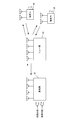
つづいて、本発明を適用した無線通信システム1について説明する。図1は、無線通信システム1の概要を説明するための図である。図1に示すように、無線通信システム1には、基地局10と、リレー局20を介して端末30(端末A及び端末B)が接続されている。
ここで、本発明を適用した無線通信システム1の概要について説明する。すなわち、本発明は複数アンテナを備えた基地局と複数の端末の間のMU-MIMO双方向通信を、リレー局を介して行う場合に、少ないリソースで効率良く実現する方法に関するものである。
具体的には、図2に示すように、1つ目の時間フレームで基地局10と端末30(端末A、B)がそれぞれリレー局20への信号伝送を行い、2つ目の時間フレームでリレー局20から基地局10及び2つの端末30へ向けて信号の報知が行われる。この時、基地局10及びリレー局20において、MU-MIMO環境下における双方向通信に適したウェイト(WTX、WRS)を送信信号にそれぞれ乗算することにより、未知の干渉が混在した信号を各端末が受信せずに済むよう制御する。このウェイト乗算制御により、各端末では、希望信号と既知の干渉のみの合成信号を受信することができ、既知の干渉を減算することにより希望信号を効率良く検出することができる。
すなわち、端末Aでは干渉減算によりu1が、端末Bでは干渉減算によりu2がそれぞれ得られることとなる。また、端末が複数アンテナを備える場合には、既知の干渉減算後の信号に対して最尤検出を行うことも可能であり、また、信号にウェイトを乗算して送受信することもできる。
また、基地局側でも既知の干渉信号の減算を行うことができ、さらに、受信ウェイト(WRX)を乗算することにより端末から送信された信号を検出することができる。すなわち、フレーム2において、基地局10では、干渉減算後、WRXを乗算すると、v1、v2が得られることとなる。また、基地局10では、既知の干渉減算後の信号に対して最尤検出を行うことも可能であり、良好な受信特性を得ることができる。
このような本発明を適用することにより、フレーム1で受信する信号(基地局と端末から送信される信号)を復号するために必要な数のアンテナをリレー局が備えていない場合においても、少ない時間リソース(フレーム数2)でMU-MIMO Two-way relayingを効率良く実現することができる。
〔第1実施形態〕
それでは、本発明を適用した第1実施形態について説明する。第1実施形態では、受信信号を元通り(送信信号と一致するよう)に補償するZF(Zero Forcing)の考え方をベースとした送受信ウェイトを用いる場合のMU-MIMO Two-way relayingについて示す。
それでは、本発明を適用した第1実施形態について説明する。第1実施形態では、受信信号を元通り(送信信号と一致するよう)に補償するZF(Zero Forcing)の考え方をベースとした送受信ウェイトを用いる場合のMU-MIMO Two-way relayingについて示す。
まず、図2に示す3つのウェイトWTX、WRS、WRXの数式表現を以下に示す。但し、基地局10、リレー局20はそれぞれ2本、2つの端末30はそれぞれ1本のアンテナを有し、図2では、基地局10からリレー局20へ信号伝送する際に信号が受ける伝搬路変動を表す行列をH、その逆(リレー局20から基地局10)をHの転置行列HTとしており、また、端末30(端末A、端末B)からリレー局20へ信号伝送する際に信号が受ける伝搬路変動を表す行列をG、その逆(リレー局20から端末30)をGの転置行列GTとしている。
詳しく述べると、基地局10のアンテナ1からリレー局20のアンテナ1へ信号が伝送される際に受ける伝搬路変動がh11、基地局10のアンテナ1からリレー局20のアンテナ2の伝搬路変動がh21、基地局10のアンテナ2からリレー局20のアンテナ1の伝搬路変動がh12、基地局10のアンテナ2からリレー局20のアンテナ2の伝搬路変動がh22である。
また、端末Aのアンテナからリレー局20のアンテナ1へ信号が伝送される際に受ける伝搬路変動がg11、端末Aのアンテナからリレー局20のアンテナ2の伝搬路変動がg21、端末Bのアンテナからリレー局20のアンテナ1の伝搬路変動がg12、端末Bのアンテナからリレー局20のアンテナ2の伝搬路変動がg22となっている。これらの伝搬路変動を式で表すと以下のようになり、基地局10及びリレー局20はこれらの行列を予め把握しているものとする。


このように、基地局10とリレー局20、端末30とリレー局20との間の伝搬路変動がHやGといった行列で表される場合に、本発明によるMU-MIMO Two-way relayingに適したウェイト(WTX、WRS、WRX)は以下のように表される。

但し、αは基地局の送信電力を正規化する係数であり、以下の式で表される。

ここで、基地局の総送信電力をPBS、基地局から送信される(WTXを乗算する前の)信号の共分散行列をQuとしており、tr(X)は行列Xのトレース(対角成分の和)を表している。また、基地局から送信される(WTXを乗算する前の)2つの信号の電力が等しいものとし、Qu=(PBS/M)Iとおくと、αは以下のように表される。

但し、Mはアンテナ数(端末数)を表しており、ここでは「2」となる。また、Iは単位行列である。

また、βはリレー局の送信電力を正規化する係数であり、以下の式で表される。ここで、リレー局の総送信電力をPRS、2つの端末から送信される信号の共分散行列をQv、リレー局における雑音電力をσRSの2乗としている。G*は行列Gの複素共役行列を表す。

ここで、Qu=(PBS/M)I、2つの端末から送信される信号の電力が等しいものとし、Qv=(PMS/M)Iとすると、βは以下のように表される。但し、端末の総送信電力(2つの端末の送信電力を合わせた電力)をPMSとしている。

また、式(6)に示すリレー局ウェイトが用いられる場合には、基地局における受信ウェイトは以下のように表される。

以上の式(3)~(9)のような送受信ウェイトを用いる場合の基地局10及び2つの端末30における受信信号を以下に示す。但し、基地局10から端末A宛の送信信号をu1、基地局から端末B宛の送信信号をu2、端末Aの送信信号をv1、端末Bの送信信号をv2としている。また、説明の簡略化のため、雑音成分は省略している。


まず、図2の1フレーム目でリレー局が受信する信号yRSは以下のように表される。

また、2フレーム目でリレー局が送信する信号xRSは以下のように表される。

この式(13)で表される信号は伝搬路を経由して、端末では以下のように受信される。

この式(14)から分かるように、本発明によるウェイトを用いた場合、端末Aでは希望信号のu1と自ら送信した既知の干渉信号v1の合成信号が受信され、未知の干渉信号は混在していない。したがって、受信信号から既知の干渉信号v1に送信電力の正規化係数βを乗算したものを減算することにより、希望信号u1を抽出することができる。
また同様に、端末Bにおいても、希望信号のu2と自ら送信した既知の干渉信号v2の合成信号が受信され、未知の干渉信号は混在していないため、受信信号から既知の干渉信号v2に送信電力の正規化係数βを乗算したものを減算することにより、希望信号u2を抽出することができる。但し、送信電力の正規化係数βについては、リレー局20から各端末30へ予め通知しておく必要がある。
このように、式(3)で表される送信ウェイトを基地局において送信信号に乗算し、式(6)で表されるウェイトをリレー局20において送信信号に乗算することにより、未知の干渉が混在した信号を各端末が受信せずに済むよう制御することができる。つまり、各端末30では希望信号と既知の干渉のみの合成信号を受信することができ、既知の干渉を減算することにより希望信号を効率良く検出することができる。
また、式(11)で表される信号は、基地局では信号yBSとして以下のように受信される。
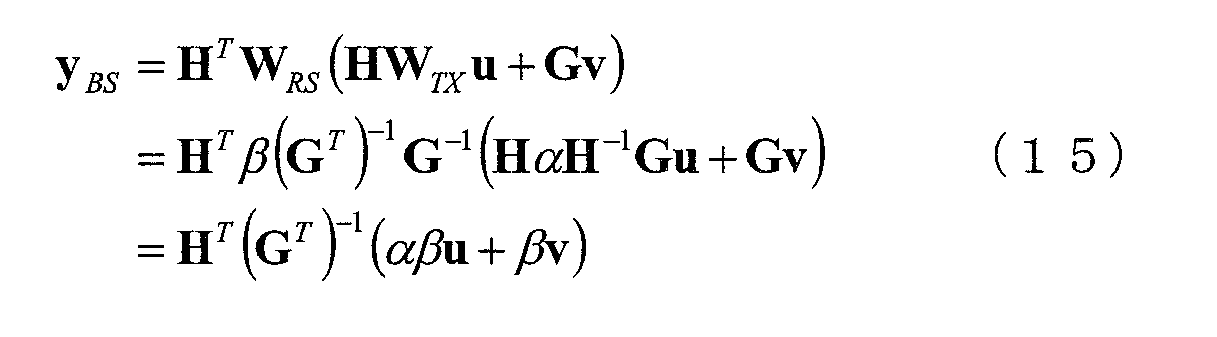
基地局ではu1とu2のいずれも把握しており、受信信号から干渉成分として減算することができる。式(15)から干渉成分を減算すると以下のようになる。

これに式(9)で表される受信ウェイトを乗算すると、
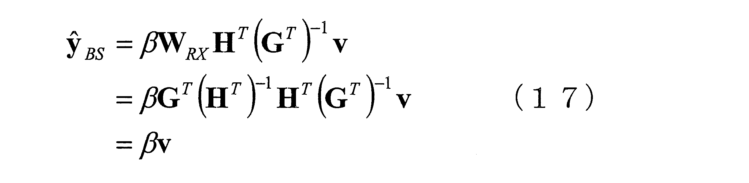
となり、希望信号vを得ることができる。ここでは、式(15)の受信信号に対して、まず干渉成分を減算してから式(9)の受信ウェイトを乗算しているが、逆に、受信ウェイトを乗算してから干渉成分を減算することでも希望信号を抽出することができる。この時の受信ウェイトは式(9)と同じでよい。
以上のように、本実施形態による送信ウェイトを基地局10及びリレー局20において信号に乗算することにより、未知の干渉が混在した信号を各端末30が受信せずに済むよう制御することが可能となり、既知の干渉信号の減算を行うことによりMU-MIMO Two-way relayingを効率良く実現することができる。また、基地局10においても干渉信号の減算と受信ウェイトの乗算を行うことにより希望信号を得ることができる。
また、ここでは基地局において既知の干渉減算後の受信信号に受信ウェイトを乗算して端末から送信された希望信号を検出する例について示したが、受信ウェイトの乗算は行わず、干渉減算後の信号に対して最尤検出(Maximum Likelihood Detection:MLD)を行うようにしてもよい。この最尤検出は、総ての送信信号候補と伝搬路推定値を乗算した結果が受信信号に最も近くなる送信信号候補を選ぶことにより信号を検出する方法であり、演算量は増加するものの、より良好な受信特性を得ることができる。
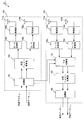
ここで、本実施の形態における基地局10の装置構成を図3に示す。図3に示すように、本実施形態における基地局10の送信部100は、変調部102と、送信ウェイト乗算部104と、D/A変換部106(106a及び106b)と、無線部108(108a及び108b)と、送信アンテナ部110(110a及び110b)(送信アンテナ1、2)とを備えて構成される。
また、受信部150は、受信アンテナ部152(152a及び152b)(受信アンテナ1、2)と、無線部154(154a及び154b)と、A/D変換部156(156a及び156b)と、干渉減算部158と、受信ウェイト乗算部160と、復調部162とを備えて構成される。
送信部100では、まず、2つの送信データ(端末A宛と端末B宛)の変調が変調部102で行われ、変調された信号に対して送信ウェイト乗算部104において式(3)で表される送信ウェイトの乗算が行われる。但し、リレー局20からのフィードバック等により、基地局10では総ての伝搬路を予め把握しているものとする。
送信ウェイト乗算部104における送信ウェイト乗算後の2つの信号は、それぞれD/A変換部106へ入力され、デジタル信号からアナログ信号へ変換される。そして、無線部108において無線送信可能な周波数帯へ周波数変換された後、送信アンテナ部110からそれぞれ送信される。
また、受信部150では、リレー局20から送信された信号がまず受信アンテナ部152で受信され、無線部154でそれぞれA/D変換可能な周波数に変換された後、A/D変換部156においてアナログ信号からデジタル信号へ変換される。
そして、干渉減算部158において干渉の減算が行われることになるが、この干渉減算部158には変調部102から自己の送信信号が入力され、既知の干渉信号として利用される。また、ここでは、既知の干渉信号に乗算されている伝搬路も把握しており、その伝搬路と自己の送信信号およびα、βといった係数が乗算された信号が干渉として減算される。この干渉減算後の信号は受信ウェイト乗算部160に入力され、式(7)で表される受信ウェイトの乗算が行われた後、復調部162で復調され、端末から送信されリレー局を経由して到来したデータが再生される。
このような基地局10の装置構成とすることにより、MU-MIMO Two-way relayingに適した送信ウェイトを乗算した信号を送信することができ、また、自己の送信信号を干渉信号として受信信号から減算し、受信ウェイトを乗算して希望信号を効率良く得ることができる。更に、先に述べたように、受信ウェイトの乗算は行わず、既知の干渉減算後の信号に対して最尤検出を行う構成としてもよい。
尚、図3では、送信アンテナと受信アンテナをそれぞれ2本ずつ設ける構成となっているが、本実施形態は送信と受信を同時に行う構成ではないため、全体で2本のアンテナを設け、切り替えスイッチによって送信と受信を切り替える構成とすることもできる。また、送信アンテナと受信アンテナを3本以上とする構成としてもよいことは勿論である。
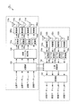
次に、本実施形態におけるリレー局20の装置構成を図4に示す。図4に示すように、本実施形態におけるリレー局20は、受信アンテナ部200(200a及び200b)と、無線部202(202a及び202b)並びに210(210a及び210b)と、A/D変換部204(204a及び204b)と、ウェイト乗算部206と、D/A変換部208(208a及び208b)と、送信アンテナ部212(212a及び212b)とを備えて構成される。
基地局10及び2つの端末30から送信された信号は、リレー局20の受信アンテナ部200で受信され、無線部202において無線周波数からA/D変換可能な周波数に周波数変換される。この信号は、次に、A/D変換部204においてアナログ信号からデジタル信号へ変換された後、ウェイト乗算部206において式(6)で表されるウェイトが乗算される。
そして、D/A変換部208においてデジタル信号からアナログ信号に変換され、無線部210において無線送信可能な周波数へ周波数変換された後に送信アンテナ部212から基地局10や端末30へ向けて送信される。
通常、リレー局では、リレー局と基地局、端末の間の距離減衰を考慮して受信信号の電力を増幅する処理が行われるが、本実施形態では、これは無線部210で行われるものとする。このようなリレー局20の装置構成とすることにより、基地局10及び端末30から送信された信号を受信し、受信信号にMU-MIMO Two-way relayingに適したウェイトを乗算し、基地局10や端末30に向けて再度送信することが可能となり、端末30が未知の干渉の混在した信号を受信せずに済むよう制御することができる。
尚、図4では、送信アンテナと受信アンテナをそれぞれ2本ずつ設ける構成となっているが、本実施形態は送信と受信を同時に行う構成ではないため、全体で2本のアンテナを設け、切り替えスイッチによって送信と受信を切り替える構成とすることもできる。また、同時にMU-MIMO通信を行う端末数(ストリーム数)と同じ数であれば、送信アンテナと受信アンテナを3本以上とする構成としてもよい。
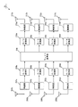
つづいて、本実施形態における端末30の装置構成を図5に示す。但し、端末30(本実施形態においては端末A、B)は同一の構成であるものとする。図5に示すように、本実施形態における端末30の送信部300は、変調部302と、D/A変換部304と、無線部306と、送信アンテナ部308とを備えて構成されている。また、受信部350は、受信アンテナ部352と、無線部354と、A/D変換部356と、干渉減算部358と、復調部360とを備えて構成されている。
この送信部300では、まず送信データが変調部302で変調され、D/A変換部304でデジタル信号からアナログ信号へ変換される。そして、無線部306において無線送信可能な周波数へ周波数変換された後、送信アンテナ部308から送信される。
また、受信部350では、受信アンテナ部352で受信された信号が無線部354においてA/D変換可能な周波数へ周波数変換され、A/D変換部356においてアナログ信号からデジタル信号へ変換される。そして、干渉減算部358において干渉の減算が行われるが、この干渉減算部358には自己の送信信号が変調部302より入力され、既知の干渉信号として利用される。
この自己の送信信号とリレー局20から予め通知された係数βが乗算された信号が、干渉信号として受信信号から減算される。このように干渉信号を減算された信号は、復調部360において復調され、基地局10から送信されリレー局20を経由して到来したデータが再生される。このような端末30の装置構成とすることにより、自己が送信した信号を干渉信号として受信信号から減算することができ、希望信号を検出することが可能となる。
尚、図5では、送信アンテナと受信アンテナをそれぞれ1本ずつ設ける構成となっているが、本実施の形態は送信と受信を同時に行う構成ではないため、全体で1本のアンテナを設け、切り替えスイッチによって送信と受信を切り替える構成とすることもできる。
以上のような基地局10、リレー局20、端末30の装置構成とすることにより、本実施の形態によるウェイトを基地局10及びリレー局20において信号に乗算することができ、未知の干渉が混在した信号を各端末が受信せずに済むよう制御することが可能となる。そして、基地局10及び端末30において既知の干渉信号の減算を行うことにより、フレーム1で受信する信号(基地局と端末から送信される信号)を復号するために必要な数のアンテナをリレー局が備えていない場合においても、少ないリソース(フレーム数2)でMU-MIMO Two-way relayingを効率良く実現することができる。
また、本実施形態では、1つ目の時間フレームと2つ目の時間フレームの伝送に用いられる周波数が同一であるものとしていたが、複数の周波数チャネルを備えたシステムにおいては、1つ目の時間フレームと2つ目の時間フレームで異なる周波数チャネルを用いるようにしてもよい。
このような場合に、例えば、1つ目の時間フレームで基地局10からリレー局20へ信号を伝送する際の伝搬路行列をH1、2つの端末30からリレー局20へ信号を伝送する際の伝搬路行列をG1、2つ目の時間フレームでリレー局20から基地局10へ信号を伝送する際の伝搬路行列をH2、リレー局20から2つの端末30へ信号を伝送する際の伝搬路行列をG2とすると、本実施の形態における送受信ウェイトはそれぞれ次のように表される。



このような送受信ウェイトを用いることにより、1つ目の時間フレームと2つ目の時間フレームで異なる周波数チャネルを用いる場合にも、未知の干渉が混在した信号を各端末が受信せずに済むよう制御することが可能となり、MU-MIMO Two-way relayingを効率良く実現することができる。
また、それぞれの装置構成については、本実施の形態で示した構成に、1つ目の時間フレームと2つ目の時間フレームで用いる周波数チャネルを切り替える周波数チャネル切り替え部を追加することにより実現することができる。
また、本実施形態では、基地局及びリレー局は全ての伝搬路変動を予め把握しているものとしている。しかし、基地局はリレー局と端末間の伝搬路変動を直接知ることができないため、総ての伝搬路変動を把握するためには、リレー局と端末間の伝搬路変動を基地局へ通知する必要がある。これに対しリレー局では、基地局及び各端末から送信された信号を直接受信することができるため、基地局との間の伝搬路及び端末との間の伝搬路を直接知ることが可能である。このため、リレー局において推定された各伝搬路行列を用いて送受信ウェイト(または送信ウェイトのみ)を算出し、算出した結果をリレー局から基地局へ通知する構成としてもよい。このような構成により、基地局とリレー局で別々にウェイトを算出せずに済み、手順の簡略化を図ることができる。
〔第2実施形態〕
第1実施形態では、ZF(Zero Forcing)の考え方をベースとした送受信ウェイトを用いる場合のMU-MIMO Two-way relayingについて示したが、この場合には、信号を元通りに補償しようとするため雑音成分を強調してしまうことがある。そこで、本発明を適用した第2実施形態では、雑音成分の影響も考慮した送受信ウェイトについて示す。
第1実施形態では、ZF(Zero Forcing)の考え方をベースとした送受信ウェイトを用いる場合のMU-MIMO Two-way relayingについて示したが、この場合には、信号を元通りに補償しようとするため雑音成分を強調してしまうことがある。そこで、本発明を適用した第2実施形態では、雑音成分の影響も考慮した送受信ウェイトについて示す。
第1実施形態と同様、図2に示す3つのウェイトWTX、WRS、WRXの数式表現を以下に示す。まず、WTXは以下のように表される。


但し、αは基地局の送信電力を正規化する係数であり以下の式で表される。また、σMSの2乗は端末の雑音電力であり、式(24)右辺第2項は( )内の行列の非対角成分のみで構成される行列を表している。

また、WRSは以下のように表される。


ここで、vec( )は、( )内の行列をベクトル表記に変形(reshape)したものであり、式(27)右辺第1項、第2項はクロネッカー積を表している。
また、βはリレー局の送信電力を正規化する係数であり以下の式で表される。

また、WRXは以下のように表される。

但し、σBSの2乗は基地局の雑音電力である。
以上のような送受信ウェイトを用いることにより、雑音の影響を考慮した重み付けを行うことができ、第1実施形態で示したウェイトを用いる場合に比べて良好な特性でMU-MIMO Two-way relayingを実現することができる。
また、本実施形態における基地局10、リレー局20、端末30は第1実施形態で示したものと同一の構成で実現することができる。但し、それぞれのウェイト乗算部で用いるウェイトや、α、βといった係数はそれぞれ本実施形態で示したものとする。
〔第3実施形態〕
以上の実施形態では、基地局10、リレー局20の受信アンテナ数をそれぞれ2、端末数を2とし、各端末はそれぞれ1つのアンテナを備えているものとしているが、それ以上の送受信アンテナ数、端末数の場合においても、その状況に対応した伝搬路行列を用いることにより本発明は適用可能である。
以上の実施形態では、基地局10、リレー局20の受信アンテナ数をそれぞれ2、端末数を2とし、各端末はそれぞれ1つのアンテナを備えているものとしているが、それ以上の送受信アンテナ数、端末数の場合においても、その状況に対応した伝搬路行列を用いることにより本発明は適用可能である。
例えば、基地局10、リレー局20の受信アンテナ数をそれぞれ4とし、1つのアンテナを備える端末が4端末存在する場合は、以上の実施形態で2×2であった伝搬路行列を4×4とし、2×1であった送信信号ベクトルを4×1とすることに対応しており、このような対応を行うことによりこれまでに示したウェイトを2×2の場合と同様に用いることができる。
また、図6に示すように基地局10、リレー局20の受信アンテナ数をそれぞれ4とし、それぞれ2つのアンテナを備える端末が2端末存在する場合にも、これまでの実施形態で示したウェイトを用いてMU-MIMO Two-way relayingを実現することができる。これらと同様に、基地局10、リレー局20の受信アンテナ数をそれぞれ4とし、3つのアンテナを備える端末と1つのアンテナを備える端末の2端末が存在する場合にも、本発明は適用可能である。
しかし、これらのウェイトは、基地局から送信される各ストリーム(WTXを乗算する前の変調信号)が端末側で分離されて受信されるようにするウェイトであるが、図6に示すように、端末が複数のアンテナを備える場合には必ずしも総てのストリームを分離するようなウェイトを用いる必要はなく、端末にとって未知の干渉が到来しないようなウェイトであればよい。
これは、例えば、図6に示す端末Aにとっての干渉信号はu3、u4、v3、v4であり、これらの信号は端末Aの受信信号に混在しないようにする必要があるが、u1、u2は希望信号であり、v1、v2はいずれも既知の干渉である。したがって、基地局とリレー局のウェイト制御によりこれらの信号(u1、u2、v1、v2)を分離する必要はなく、これらの信号が混在した(加算された)信号を端末が受信し、端末での処理によりこれらを分離して希望信号を検出する構成としてもよい。
そこで、以下の実施形態では、端末が複数のアンテナを備える場合に、各ストリームを完全に分離することなく端末が未知の干渉を受信せずに済むようなウェイト制御について示す。
まず第3実施形態では、図6に示すように基地局10、リレー局20の受信アンテナ数をそれぞれ4とし、それぞれ2つのアンテナを備える端末が2端末存在する場合について、リレー局で用いるウェイトを第1実施形態で示したものとするときの基地局において用いるウェイトについて示す。第1実施形態におけるリレー局のウェイトは以下の式(30)で示されていた。

但し、βは式(28)で表される、リレー局における送信電力を正規化する係数であり、本実施形態では各伝搬路行列(H、G)は4×4の行列である。このウェイトを用いる場合の端末における受信信号ベクトルは式(14)より以下のように表される。ここで、WTX=αWTX’としており、簡単のため雑音成分は無視している。αは式(25)で表される、基地局における送信電力を正規化する係数である。

式(31)の右辺第2項からわかるように、式(30)で示すウェイトをリレー局で用いる場合には、2つの端末から送信された信号(ストリーム)は完全に分離されてそれぞれの端末で受信されることとなり、別の端末から送信された未知の干渉が受信信号に混在することはない。したがって、各端末で自身の送信信号にβを乗算した結果を受信信号から減算することにより、既知の干渉成分を除去することができる。
式(31)の右辺第1項は基地局から端末宛に送信された希望信号成分を表しているが、別の端末宛の信号は(例えば、端末A宛の信号は端末Bにとって)未知の干渉となるため、このような未知の干渉がそれぞれの端末で受信せずに済むようなウェイト制御を基地局において行う必要がある。
このような目的のために、第1、第2実施形態では、端末宛の4つの信号(ストリーム)が総て分離されてそれぞれの端末で受信されるように制御していたが、本実施形態ではこれらとは異なるウェイト制御について示す。ここで、式(31)の第1項より、基地局から送信された信号が各端末で受信されるまでに経由する仮想的な伝搬路をF=G-1Hとおく。本実施形態におけるウェイト制御は、この伝搬路Fにブロック対角化と呼ばれる処理を適用して、各ストリームを完全に分離することなく端末が未知の干渉を受信せずに済むようにするものである。
本実施形態に適したブロック対角化(Block Diagonalization)について以下に説明する。説明のため、仮想伝搬路Fを以下のように表す。
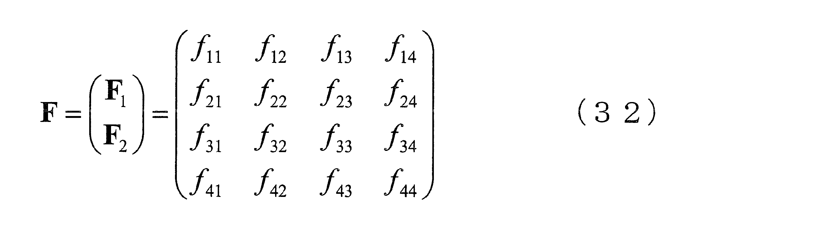
本実施形態に適したブロック対角化(Block Diagonalization)について以下に説明する。説明のため、仮想伝搬路Fを以下のように表す。
ここで、F1、F2はいずれも2×4の行列であり、F1は端末Aで受信される信号が経由する伝搬路を、F2は端末Bで受信される信号が経由する伝搬路をそれぞれ示している。本実施形態で適用するブロック対角化では、まず、このような伝搬路Fを構成するF1、F2に対してそれぞれ特異値分解(Singular Value Decomposition)を行う。特異値分解とは、m×nの行列Jを、m×mのユニタリ行列S、対角成分以外は0で対角成分は行列Jの特異値となるm×nの行列D、n×nのユニタリ行列の複素共役転置行列THの積で表すことであり、以下のように書くことができる。

この特異値分解を式(32)のF1、F2にそれぞれ施すと以下のように表すことができる。
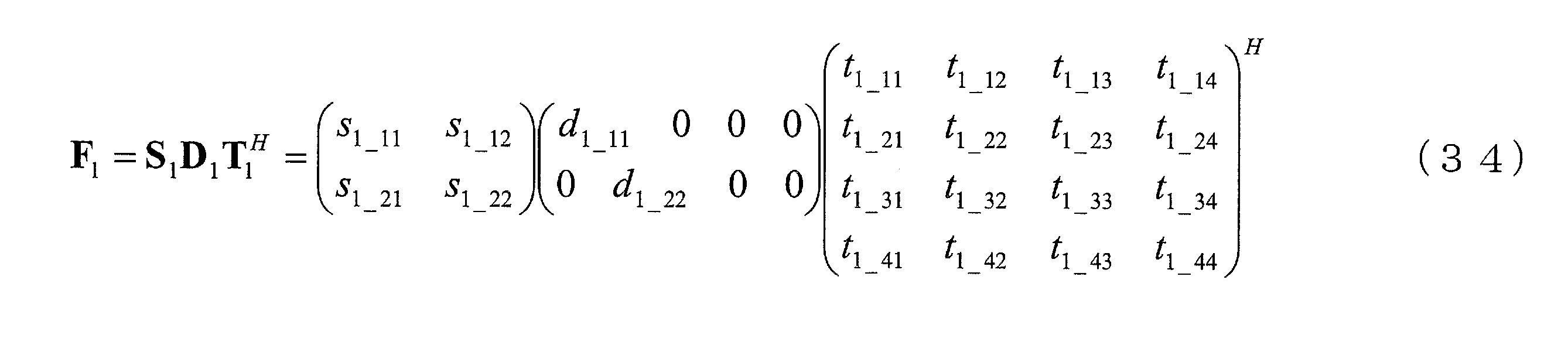

ここで、式(34)の両辺に右側からT1を乗算すると、T1はユニタリ行列であることから以下のようになる。

この結果より、F1の1行目とT1の3列目、4列目の積はいずれも0となることがわかる。また、F1の2行目とT1の3列目、4列目の積も同様に0となることがわかる。これは、つまり、T1の3列目、4列目を乗算された信号がF1の伝搬路を経由すると、受信側では信号が全く受信されないということを示しており、F2について特異値分解を行った結果についても同様のことが言える。
このような性質を利用して、基地局から送信される信号のうち、各端末にとっての未知の干渉を端末が受信せずに済むように制御する、つまり仮想的な伝搬路Fをブロック対角化することができる基地局の送信ウェイトは以下のように表すことができる。

この式(37)で表される送信ウェイトを基地局で用いた場合には、式(31)の右辺第1項は以下のように表される。
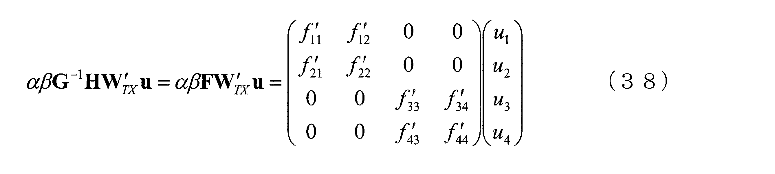
但し、f’
11等は以下の式で表される。

式(38)より、端末Aで受信される信号はu1とu2が合成された信号でありu3、u4は混在していないことがわかる。また、端末Bで受信される信号についても同様に、u3とu4の合成信号であるが、u1とu2は混在していない。つまり、ブロック対角化を施した送信ウェイトを基地局で乗算した信号を送信することにより、各端末にとっての希望信号が混在した信号(ストリーム毎に分離されていない信号)を受信し、基地局が別の端末宛に送信する未知の干渉は受信せずに済むように制御できている。
このように、ブロック対角化を施した式(37)で示される送信ウェイトを基地局で用い、式(30)で示されるウェイトをリレー局において用いることにより、各端末にとって未知の干渉が混在した信号を受信せずに済むように制御することができる。
各端末では、受信信号から既知の干渉信号(式(31)の右辺第2項)を減算した後に残った、希望信号の合成信号に対して最尤検出等を行って、希望信号(ストリーム)を分離すればよい。線形ウェイトを乗算することにより各希望信号(ストリーム)が総て分離されて端末で受信される第1、第2実施形態に比べ、本実施形態では、異なる端末宛のストリームは線形ウェイトにより分離するものの、一つの端末宛の複数ストリームは分離しないため、アンテナ間に相関がある場合等、線形処理による分離が適さない状況においては良好な受信特性が得られる可能性が高まる。
但し、式(38)で示す行列の左上の2×2の行列を端末Aで、右下の2×2の行列を端末Bでそれぞれ把握しておく必要がある。このためには、データ信号の伝送に先立って、既知の伝搬路推定用信号を基地局から送信する必要があるが、この際に、データ信号の伝送時と同じウェイトを基地局及びリレー局において乗算し、それらの処理を施された伝搬路推定用信号を受信することにより、必要な仮想伝搬路の変動を推定することができる。また、最尤検出を行わず、受信信号に対してZF、MMSE(Minimum Mean Square Error)等の線形処理を行って信号検出する構成としてもよい。
一方、基地局側では、希望信号と上述の基地局送信ウェイトが乗算された自身の送信信号が混在した信号が受信されるが、基地局送信ウェイトが乗算された自身の送信信号は既知の干渉であるため、これまでの実施形態と同様に受信信号から減算できる。
本実施形態では、リレー局において第1実施形態と同一のウェイトを乗算しているため、既知の干渉減算後の信号は第1実施形態と同じ信号となる。したがって、第1実施形態と同一の受信ウェイトを乗算して希望信号を検出することが可能であり、また、最尤検出を行うこともできる。
ここで、本実施の形態における基地局10の装置構成を図7に示す。図7に示すように、本実施形態における基地局10は、図3に示す装置のアンテナ数を増やした構成となっており、図3と共通の符号を付している。但し、図7に示す基地局装置では受信ウェイトの乗算は行わず、復調部162において希望信号の最尤検出を行う構成としている。また、この基地局装置では、送信ウェイト乗算部104において上述のブロック対角化を適用した送信ウェイトが乗算されることとなる。
次に、本実施形態におけるリレー局20の装置構成を図8に示す。図8に示すように、本実施形態におけるリレー局20は、図4に示す装置のアンテナ数を増やした構成となっており、図4と共通の符号を付している。先に述べたように、ウェイト乗算部206で乗算されるウェイトは、第1実施形態で示したウェイトと同じ式で表すことができるものである。
次に、本実施形態における端末30の装置構成を図9に示す。図9に示すように、本実施形態における端末30は、図5に示す装置のアンテナ数を増やした構成となっており、図5と共通の符号を付している。
但し、送信する信号(ストリーム)は2つであり、v1とv2の組かv3とv4の組のいずれかが送信されることとなる。また、先に述べたように、本実施形態では、2つの希望信号(ストリーム)が分離されずに受信されるため、端末側の受信処理により希望信号を分離して検出する必要があるが、図9に示す端末装置では、復調部360において最尤検出を行うものとしている。
以上のような装置構成とし、先に示したブロック対角化を施した送信ウェイトを乗算した信号を送信することにより、希望信号をストリーム毎に完全に分離することなく端末が未知の干渉を受信せずに済むように制御することができる。
〔第4実施形態〕
第3実施形態では、ブロック対角化により算出したウェイトを基地局において用い、リレー局においてZFの考え方をベースとしたウェイトを用いる場合について示したが、基地局と同様にリレー局においてもブロック対角化を利用して算出したウェイトを用いて信号の伝送を行うことができる。第4実施形態では、ブロック対角化を利用して算出したウェイトをリレー局でも用いる場合について示す。
第3実施形態では、ブロック対角化により算出したウェイトを基地局において用い、リレー局においてZFの考え方をベースとしたウェイトを用いる場合について示したが、基地局と同様にリレー局においてもブロック対角化を利用して算出したウェイトを用いて信号の伝送を行うことができる。第4実施形態では、ブロック対角化を利用して算出したウェイトをリレー局でも用いる場合について示す。
まず、式(14)や式(31)の第1式にも示すように、本発明によるMU-MIMO Two-way Relayingを行う場合の端末における受信信号は以下のように表される。但し、簡単のため、雑音成分は無視している。

この式(40)の第2項は、フレーム1で各端末から送信されリレー局で受信された信号に、リレー局でウェイトを乗算し、フレーム2でリレー局から送信された信号を表しており、自身が送信した既知の干渉と別の端末から送信された未知の干渉が含まれる項である。本発明によるMU-MIMO Two-way Relayingを実現するためには、まず、各端末の受信信号に別の端末から送信された未知の干渉が混在しないようにWRSで制御する必要がある。本実施の形態ではブロック対角化を用いてWRSを算出するが、ここで、式(40)の第2項を以下のように書き直す。但し、βは式(28)で表される、リレー局における送信電力を正規化する係数である。

この式(41)では、リレー局ウェイトWRSをW’RS1とW’RS2の積で表すように式(40)の第2項を書き直している。このうち、W’RS1は左側に乗算されているGTを第3実施形態における仮想伝搬路Fとみなしてブロック対角化を行うための行列であり、W’RS2は右側に乗算されているGを第3実施形態における仮想伝搬路Fとみなしてブロック対角化を行うための行列である。つまり、GTW’RS1が式(38)で示すようなブロック対角化された行列となり、W’RS2Gも同様にブロック対角化された行列となる。
そして、それらの積(GTW’RS1W’RS2G)もやはりブロック対角化された行列となるため、以上のような2回のブロック対角化を行うことにより、式(40)第2項において各端末の受信信号に別の端末から送信された未知の干渉が混在しないように制御可能なWRS(=W’RS1W’RS2)を得ることができる。
但し、W’RS1の算出は第3実施形態で示したものと同じ要領で行うことができるが、W’RS2は少し異なる手順で算出する必要がある。これは、ブロック対角化する対象の仮想伝搬路行列GがW’RS2の右側に乗算されているためであり、第3実施形態の式(32)に対応する仮想伝搬路行列は以下のように表される。
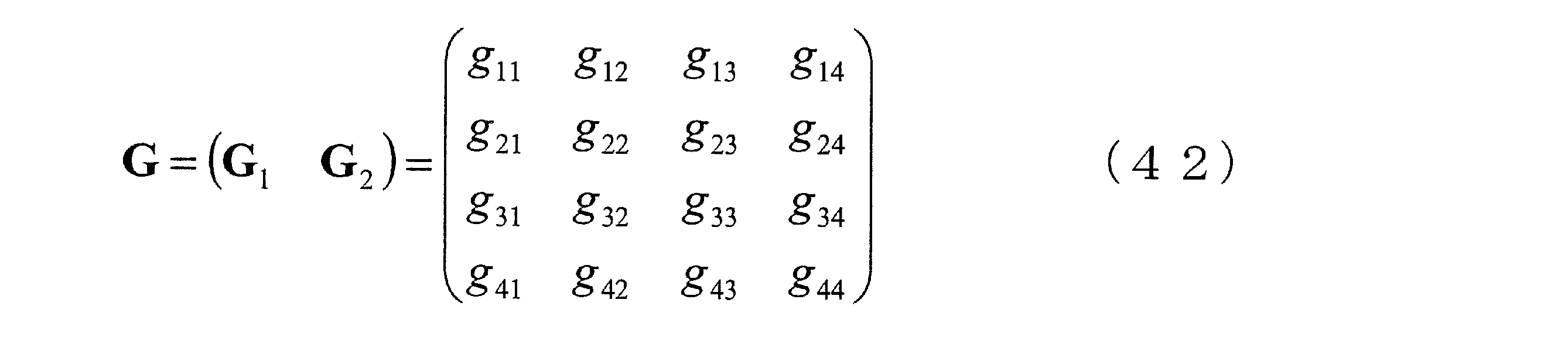
ここで、G1、G2はいずれも4×2の行列である。これらの行列G1、G2について特異値分解すると、その結果はそれぞれ以下のようになる。


このように得られたユニタリ行列S1とS2を用いて、W’RS2は以下のように得られる。

但し、s*はsの複素共役を表している。このような手順によりW’RS2が得られ、W’RS1と併せて、フレーム1で各端末から送信され、フレーム2でリレー局から送信される信号が経由する仮想伝搬路行列をブロック対角化することができ、自身が送信した既知の信号(干渉)はストリーム毎に分離せずに、別の端末から送信された未知の干渉を各端末が受信せずに済むように制御することができる。そして、端末では、ブロック対角化された行列のうち、自身の受信信号に含まれる小行列を把握することにより既知の干渉を減算することができる。
また、基地局で用いる送信ウェイトについては、第3実施形態における仮想伝搬路行列FをF=GTWRSG(但し、WRSは本実施形態で得られるウェイト)とおいて、第3実施形態と同様のブロック対角化を行うことにより得ることができる。
このようにブロック対角化された信号を受信する端末では、第3実施形態と同様に、既知の干渉減算後に最尤検出や受信ウェイトの乗算等を行って希望信号を検出することができる。基地局においても、これまでの実施形態と同様に、既知の干渉減算後に最尤検出や受信ウェイトの乗算等を行って希望信号を検出することができる。
以上のように、本実施形態では、リレー局においてもブロック対角化を利用したウェイトを用いる例について示したが、本実施形態における基地局、リレー局、端末のそれぞれの装置は第3実施形態で示したもの(図7、8,9)と同一の構成で実現することができる。
〔第5実施形態〕
第3、第4実施形態では、基地局10、リレー局20の受信アンテナ数がそれぞれ4で、それぞれ2つのアンテナを備える端末が2端末存在するような場合、つまり各端末が備えるアンテナ数が同じである場合について、ブロック対角化を利用したウェイトについて示したが、本発明によるMU-MIMO Two-way Relayingは、図10に示すようにアンテナ数が異なる端末が存在する場合についても対応可能である。第5実施形態では、このような場合のウェイト制御について述べる。
第3、第4実施形態では、基地局10、リレー局20の受信アンテナ数がそれぞれ4で、それぞれ2つのアンテナを備える端末が2端末存在するような場合、つまり各端末が備えるアンテナ数が同じである場合について、ブロック対角化を利用したウェイトについて示したが、本発明によるMU-MIMO Two-way Relayingは、図10に示すようにアンテナ数が異なる端末が存在する場合についても対応可能である。第5実施形態では、このような場合のウェイト制御について述べる。
まず、第1、第2実施形態で示したように、総てのストリームが分離されて受信されるような制御は、図10に示すような場合においても同様に適用可能である。
また、第3、第4実施形態で示したようなブロック対角化を利用したウェイトによる制御についても、適用可能である。但し、端末Aと端末Bでは希望信号(ストリーム)の数、干渉(ストリーム)の数が異なるため、このことを考慮したブロック対角化を行う必要がある。
ここで、第3実施形態を例にとると、具体的には、式(32)の仮想伝搬路行列を構成するF1を3×4の行列、F2を1×4の行列として、以降の演算を行う必要がある。この時、第3実施形態と同様に、F1は端末Aで受信される信号が経由する伝搬路を、F2は端末Bで受信される信号が経由する伝搬路をそれぞれ示している。これらF1、F2を第3実施形態と同様に特異値分解すると以下のように表すことができる。
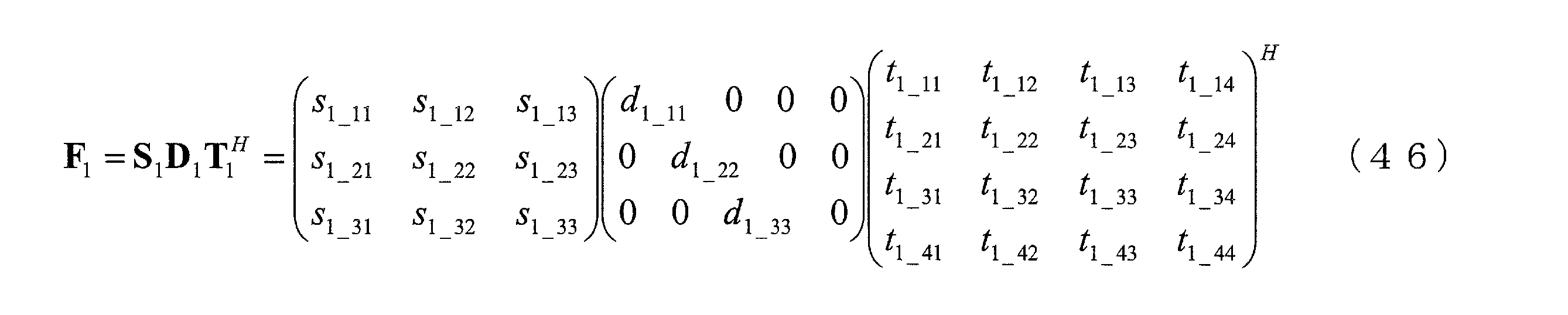
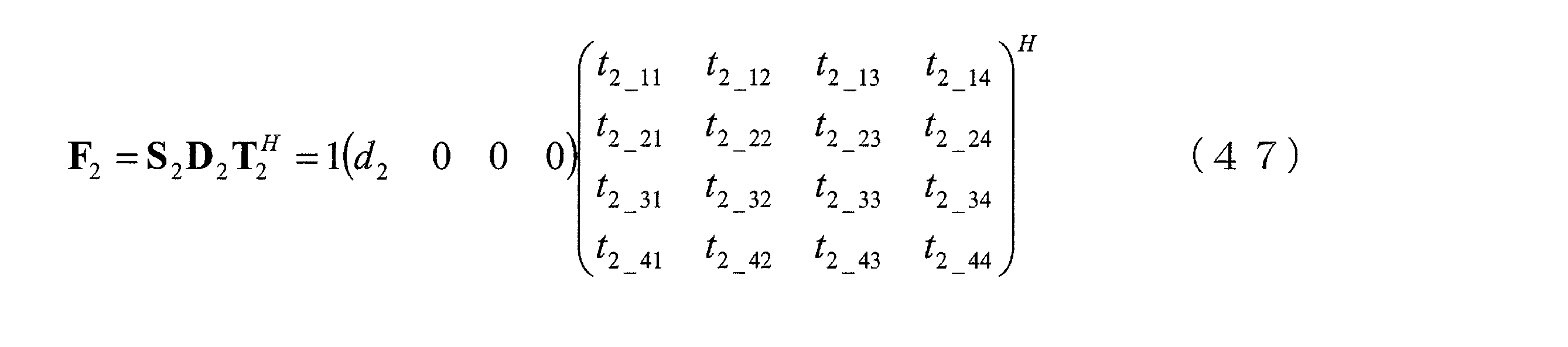
そして、仮想的な伝搬路Fをブロック対角化することができる基地局の送信ウェイトは以下のように表される。
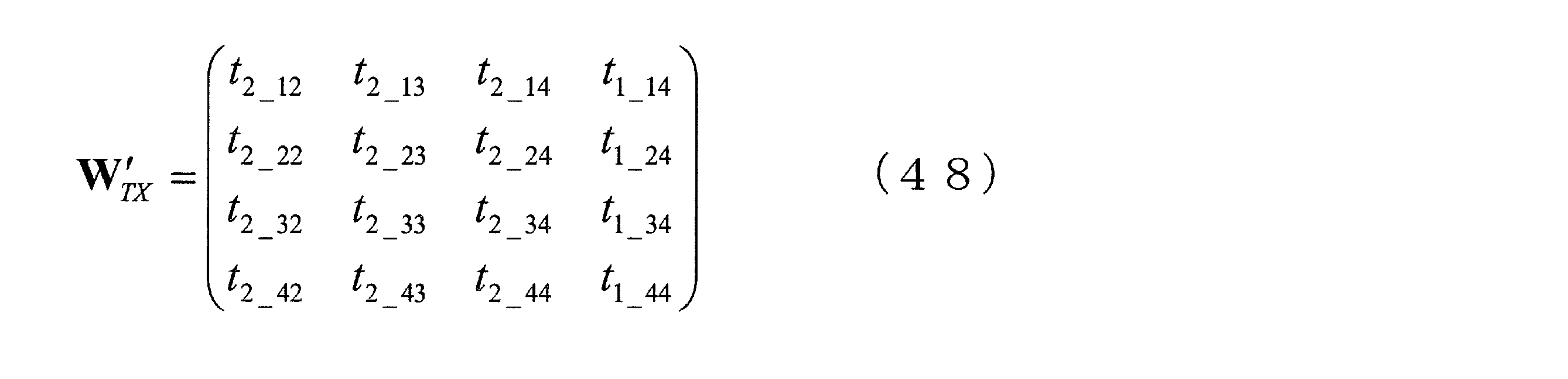
このようなウェイトを用いることにより、図10に示すような異なる数のアンテナを備えた複数の端末が存在する場合にも、基地局から送信された信号が端末に到来する際に経由する伝搬路をブロック対角化することができ、総てのストリームを分離しないような制御を行いつつ、未知の干渉が各端末で受信されないようにすることができる。
ここでは、第3実施形態を例としたが、第4実施形態のようにリレー局におけるブロック対角化を利用したウェイト制御についても同様に適用することができ、図10に示すような異なる数のアンテナを備えた複数の端末が存在する場合のMU-MIMO Two-way Relayingを実現することができる。
このように、本発明によるMU-MIMO Two-way Relayingでは、総ての端末が同じ数のアンテナを備えている必要はなく、異なる数のアンテナを備えた端末が複数存在する状況においても、リレー局を介した効率の良い伝送を行うことができる。
また、以上の実施形態では、2つの端末と双方向通信を行う複数アンテナを備えた装置を基地局と呼び、基地局と端末の双方向通信を中継する複数アンテナを備えた装置をリレー局と呼んでいるが、複数アンテナを備えた端末が複数の端末と双方向通信を行うようなシステムにおいても本発明は適用可能であり、さらに、中継を専門とするリレー局ではなく、通常は基地局として動作する装置がリレー局の役割を担うようにしてもよい。また、複数のアンテナを備える端末がリレー局として動作する構成の場合にも、本発明は適用可能である。
さらに、基地局送信ウェイトとリレー局送信ウェイトの最適化を図るためには、まず最適化基準(伝送レートを最も高く、またはMSE(Mean Square Error)を最小に、等)を設定し、それらの基準に対応するそれぞれのウェイトの式を算出する。このように得られた基地局送信ウェイトとリレー局送信ウェイトは、それぞれ相互に関連し合っているため、一度の演算で最適値を得ることはできず、繰り返し演算により最適化を図らなければならない。
具体的には、どちらかのウェイトを初期化し、初期化したウェイトを用いて別のウェイトの算出を行う。そして、算出されたウェイトを用いて、もう一方のウェイト(先に初期化した方のウェイト)の値の更新を行うといった処理を2つのウェイトの値が収束するまで繰り返し行う。そして最終的に得られた値が、それぞれの最適化基準における最適ウェイトと言うことができる。本発明による基地局送信ウェイトとリレー局送信ウェイトは、このような繰り返し処理によっても求めることができる。
1 無線通信システム
10 基地局
100 送信部
102 変調部
104 送信ウェイト乗算部
106、106a、106b D/A変換部
108、108a、108b 無線部
110、110a、110b 送信アンテナ部
150 受信部
152、152a、152b 受信アンテナ部
154、154a、154b 無線部
156、156a、156b A/D変換部
158 干渉減算部
160 受信ウェイト乗算部
162 復調部
20 リレー局
200、200a、200b 受信アンテナ部
202、202a、202b 無線部
204、204a、204b A/D変換部
206 ウェイト乗算部
208、208a、208b D/A変換部
210、210a、210b 無線部
212、212a、212b 送信アンテナ部
30 端末
300 送信部
302 変調部
304 D/A変換部
306 無線部
308 送信アンテナ部
350 受信部
352 受信アンテナ部
354 無線部
356 A/D変換部
358 干渉減算部
360 復調部
10 基地局
100 送信部
102 変調部
104 送信ウェイト乗算部
106、106a、106b D/A変換部
108、108a、108b 無線部
110、110a、110b 送信アンテナ部
150 受信部
152、152a、152b 受信アンテナ部
154、154a、154b 無線部
156、156a、156b A/D変換部
158 干渉減算部
160 受信ウェイト乗算部
162 復調部
20 リレー局
200、200a、200b 受信アンテナ部
202、202a、202b 無線部
204、204a、204b A/D変換部
206 ウェイト乗算部
208、208a、208b D/A変換部
210、210a、210b 無線部
212、212a、212b 送信アンテナ部
30 端末
300 送信部
302 変調部
304 D/A変換部
306 無線部
308 送信アンテナ部
350 受信部
352 受信アンテナ部
354 無線部
356 A/D変換部
358 干渉減算部
360 復調部
Claims (24)
- 複数の送受信アンテナを備えた基地局と複数の端末とが同じ周波数を用いて、複数の送受信アンテナを備えたリレー局を介して双方向の通信を行う無線通信システムであって、
第一の時間フレームにおいて基地局と複数の端末とが同時にリレー局へ信号を送信し、
前記リレー局は、
前記第一の時間フレームにおいて送信された信号を受信信号として受信する受信手段と、
前記受信信号にリレー局送信ウェイトWRSを乗算して送信信号を生成し、該送信信号を第二の時間フレームにおいて基地局と複数の端末とへ送信する送信手段と、
を備えることを特徴とする無線通信システム。 - 前記リレー局送信ウェイトWRSは少なくともリレー局と端末との間の伝搬路を基に生成されるものであることを特徴とする請求項1に記載の無線通信システム。
- 前記第一の時間フレームにおいて基地局から送信される信号は、変調信号に基地局送信ウェイトWTXを乗算した信号であることを特徴とする請求項1または請求項2に記載の無線通信システム。
- 前記基地局送信ウェイトWTXは、少なくとも基地局とリレー局との間の伝搬路又はリレー局と端末との間の伝搬路を基に生成されるものであることを特徴とする請求項3に記載の無線通信システム。
- 前記リレー局送信ウェイトWRS、前記基地局送信ウェイトWTXは、基地局の送信ストリームが総て分離されて各端末で受信されるように生成されるものであることを特徴とする請求項4に記載の無線通信システム。
- 前記第二の時間フレームにおいてリレー局から送信された信号を受信した前記端末は、前記第一の時間フレームにおいて自己がそれぞれ送信した信号を基に干渉信号を生成し、前記生成された干渉信号を受信信号から減算することにより前記第一のフレームにおいて基地局から送信された信号を検出することを特徴とする請求項3から請求項5のいずれかに記載の無線通信システム。
- 前記第二の時間フレームにおいてリレー局から送信された信号を受信した前記基地局は、前記第一の時間フレームにおいて自己が送信した信号を基に干渉信号を生成し、前記生成された干渉信号を受信信号から減算し、前記干渉信号減算後の信号に受信ウェイトWRXを乗算することにより端末から送信された信号を検出することを特徴とする請求項3から請求項6のいずれかに記載の無線通信システム。
- 前記受信ウェイトWRXは、少なくとも基地局とリレー局の間の伝搬路またはリレー局と端末との間の伝搬路を基に生成されるものであることを特徴とする請求項7に記載の無線通信システム。
- 前記リレー局送信ウェイトWRS、前記基地局送信ウェイトWTX、前記受信ウェイトWRXは、基地局とリレー局との間の伝搬路行列をH、リレー局と複数の端末の間の伝搬路行列をG、基地局の総送信電力をPBS、リレー局の総送信電力をPRS、端末の送信電力の合計をPMS、前記第一の送信ウェイトWTXを乗算する前の基地局の送信信号の共分散行列を単位行列、端末のアンテナ数の合計をM、リレー局の雑音電力をσRSの2乗とする場合に、

- 前記リレー局送信ウェイトWRS、前記基地局送信ウェイトWTX、前記受信ウェイトWRXは、基地局とリレー局との間の伝搬路行列をH、リレー局と複数の端末の間の伝搬路行列をG、基地局の総送信電力をPBS、リレー局の総送信電力をPRS、端末の送信電力の合計をPMS、前記基地局送信ウェイトWTXを乗算する前の基地局の送信信号の共分散行列をQu、基地局の送信信号の共分散行列をQv、端末のアンテナ数の合計をM、基地局の雑音電力をσBSの2乗、リレー局の雑音電力をσRSの2乗、端末の雑音電力をσMSの2乗とする場合に、
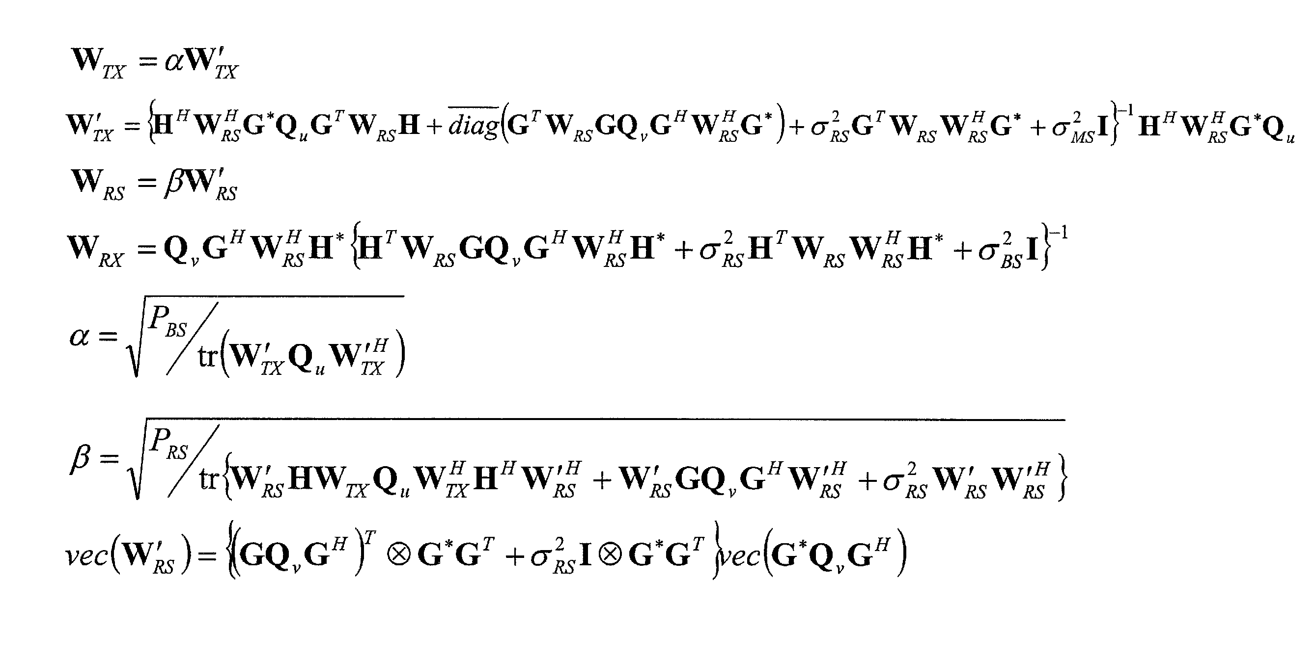
- 前記複数の端末は、総て同じ数のアンテナを備えることを特徴とする請求項1から請求項10のいずれかに記載の無線通信システム。
- 前記複数の端末は、それぞれ複数のアンテナを備えることを特徴とする請求項1から請求項11のいずれかに記載の無線通信システム。
- 複数の送受信アンテナを備え、複数の送受信アンテナを備えたリレー局を介して複数の端末と同じ周波数を用いた双方向の通信を行う基地局であって、
前記複数の端末宛の信号を第一の時間フレームにおいてリレー局へ向けて送信する送信手段と、
第二の時間フレームにおいてリレー局から送信された信号を受信する受信手段と、
を備えることを特徴とする基地局。 - 前記送信手段は、変調信号に基地局送信ウェイトWTXを乗算した信号を送信することを特徴とする請求項13に記載の基地局。
- 前記基地局送信ウェイトWTXを、少なくとも基地局とリレー局との間の伝搬路又はリレー局と端末との間の伝搬路を基に生成することを特徴とする請求項14に記載の基地局。
- 前記基地局送信ウェイトWTXは、基地局の送信ストリームが総て分離されて各端末で受信されるように生成されるものであることを特徴とする請求項15に記載の基地局。
- 前記第一の時間フレームにおいて自己が送信した信号を基に干渉信号を生成する干渉信号生成手段と、
前記受信手段により受信された前記第二の時間フレームにおける信号から前記生成された干渉信号を減算する干渉減算手段と、
を更に備えることを特徴とする請求項15又は請求項16に記載の基地局。 - 前記干渉減算手段による干渉信号減算後の信号に受信ウェイトWRXを乗算する受信ウェイト乗算手段と、
前記端末から送信された信号を、前記受信ウェイトWRX乗算後に検出する手段と、
を更に備えることを特徴とする請求項15から請求項17のいずれかに記載の基地局。 - 前記受信ウェイトWRXを、少なくとも基地局とリレー局との間の伝搬路又はリレー局と端末との間の伝搬路を基に生成することを特徴とする請求項18に記載の基地局。
- 複数の送受信アンテナを備え、複数の送受信アンテナを備えた基地局と複数の端末との双方向の通信を同じ周波数を用いて中継するリレー局であって、
第一の時間フレームにおいて前記基地局と前記端末とから送信された信号を受信信号として受信する受信手段と、
前記第一の時間フレームにおける受信信号にリレー局送信ウェイトWRSを乗算して生成された信号を第二の時間フレームにおいて送信信号として送信する送信手段と、
を備えることを特徴とするリレー局。 - 前記リレー局送信ウェイトWRSを、少なくともリレー局と端末との間の伝搬路を基に生成することを特徴とする請求項20に記載のリレー局。
- 前記基地局送信ウェイトWRSは、前記基地局の送信ストリームが総て分離されて前記各端末で受信されるように生成されるものであることを特徴とする請求項21に記載のリレー局。
- 複数の送受信アンテナを備えた基地局や他の端末と同じ周波数を用いて、複数の送受信アンテナを備えたリレー局を介して前記基地局との双方向の通信を行う端末であって、
前記基地局宛の信号を第一の時間フレームにおいてリレー局へ向けて送信する送信手段と、
第二の時間フレームにおいてリレー局から送信された信号を受信する受信手段と、
を備えることを特徴とする端末。 - 前記第一の時間フレームにおいて自己が送信した信号を基に干渉信号を生成する干渉信号生成手段と、
前記生成された干渉信号を前記第二の時間フレームにおける受信信号から減算する減算手段と、
を更に備えることを特徴とする請求項23に記載の端末。
Priority Applications (1)
| Application Number | Priority Date | Filing Date | Title |
|---|---|---|---|
| EP10755900A EP2413517A1 (en) | 2009-03-27 | 2010-03-15 | Wireless communication system, base station, relay station, and terminal |
Applications Claiming Priority (4)
| Application Number | Priority Date | Filing Date | Title |
|---|---|---|---|
| JP2009-078470 | 2009-03-27 | ||
| JP2009078470 | 2009-03-27 | ||
| JP2009-241048 | 2009-10-20 | ||
| JP2009241048A JP5473528B2 (ja) | 2009-03-27 | 2009-10-20 | 無線通信システム、基地局、リレー局及び端末 |
Publications (1)
| Publication Number | Publication Date |
|---|---|
| WO2010110102A1 true WO2010110102A1 (ja) | 2010-09-30 |
Family
ID=42780794
Family Applications (1)
| Application Number | Title | Priority Date | Filing Date |
|---|---|---|---|
| PCT/JP2010/054303 Ceased WO2010110102A1 (ja) | 2009-03-27 | 2010-03-15 | 無線通信システム、基地局、リレー局及び端末 |
Country Status (3)
| Country | Link |
|---|---|
| EP (1) | EP2413517A1 (ja) |
| JP (1) | JP5473528B2 (ja) |
| WO (1) | WO2010110102A1 (ja) |
Cited By (1)
| Publication number | Priority date | Publication date | Assignee | Title |
|---|---|---|---|---|
| WO2013018455A1 (ja) * | 2011-07-29 | 2013-02-07 | シャープ株式会社 | 無線通信システム、リレー局装置、通信装置、無線通信方法 |
Families Citing this family (9)
| Publication number | Priority date | Publication date | Assignee | Title |
|---|---|---|---|---|
| KR101650937B1 (ko) | 2010-07-29 | 2016-08-24 | 톰슨 라이센싱 | 3노드 양방향 협력을 위한 다중 입력-다중 출력 네트워크 코딩된 증폭 및 전달 릴레이 구조 |
| JP5451680B2 (ja) * | 2011-04-25 | 2014-03-26 | 株式会社Nttドコモ | 移動通信端末 |
| JP2012257190A (ja) * | 2011-05-16 | 2012-12-27 | Nagoya Institute Of Technology | 通信システム |
| US9124475B2 (en) * | 2011-09-19 | 2015-09-01 | Alcatel Lucent | Method and apparatus for interference cancellation for antenna arrays |
| JP2013219664A (ja) * | 2012-04-11 | 2013-10-24 | Nippon Telegr & Teleph Corp <Ntt> | 無線通信システム、通信装置、中継装置、及び無線通信方法 |
| CN104811213B (zh) * | 2014-01-28 | 2018-03-09 | 华为技术有限公司 | 自干扰信号消除设备及方法 |
| JP6459579B2 (ja) * | 2015-02-06 | 2019-01-30 | 株式会社デンソー | 無線通信システム、基地局 |
| JP7208489B2 (ja) * | 2018-12-21 | 2023-01-19 | 日本電信電話株式会社 | 無線中継システム及び無線中継方法 |
| CN113271134B (zh) * | 2020-02-17 | 2023-07-25 | 北京紫光展锐通信技术有限公司 | Ue的中继通信方法及相关产品 |
Family Cites Families (1)
| Publication number | Priority date | Publication date | Assignee | Title |
|---|---|---|---|---|
| DE602008000755D1 (de) * | 2008-01-11 | 2010-04-15 | Ntt Docomo Inc | Verfahren, Vorrichtung und System zur Kanalschätzung in Zwei-Wege-Relais-Netzwerken |
-
2009
- 2009-10-20 JP JP2009241048A patent/JP5473528B2/ja not_active Expired - Fee Related
-
2010
- 2010-03-15 EP EP10755900A patent/EP2413517A1/en not_active Withdrawn
- 2010-03-15 WO PCT/JP2010/054303 patent/WO2010110102A1/ja not_active Ceased
Non-Patent Citations (5)
| Title |
|---|
| CELAL ESLI ET AL.: "Multiuser MIMO two-way relaying for cellular communications", IEEE PERSONAL, INDOOR AND MOBILE RADIO COMMUNICATIONS, 15 September 2008 (2008-09-15), pages 1 - 6, XP031371654 * |
| L. WENG ET AL.: "MU-MIMO Relaying System with Self-interference Cancellation", WCNC, March 2007 (2007-03-01) |
| LINGFAN WENG ET AL.: "Multi-User MIMO Relay System with Self-Interference Cancellation", IEEE WIRELESS COMMUNICATIONS AND NETWORKING CONFERENCE, 11 March 2007 (2007-03-11), pages 959 - 963, XP031088667 * |
| N. LEE ET AL.: "Linear Precoder and Decoder Design for Two-Way AF MIMO Relaying System", May 2008, VTC SPRING |
| NAMYOON LEE ET AL.: "Linear Precoder and Decoder Design for Two-Way AF MIMO Relaying System", IEEE VEHICULAR TECHNOLOGY CONFERENCE, 11 May 2008 (2008-05-11), pages 1221 - 1225, XP031255722 * |
Cited By (2)
| Publication number | Priority date | Publication date | Assignee | Title |
|---|---|---|---|---|
| WO2013018455A1 (ja) * | 2011-07-29 | 2013-02-07 | シャープ株式会社 | 無線通信システム、リレー局装置、通信装置、無線通信方法 |
| JP2013031095A (ja) * | 2011-07-29 | 2013-02-07 | Sharp Corp | 無線通信システム、リレー局装置、通信装置、無線通信方法 |
Also Published As
| Publication number | Publication date |
|---|---|
| JP2010252292A (ja) | 2010-11-04 |
| JP5473528B2 (ja) | 2014-04-16 |
| EP2413517A1 (en) | 2012-02-01 |
Similar Documents
| Publication | Publication Date | Title |
|---|---|---|
| JP5473528B2 (ja) | 無線通信システム、基地局、リレー局及び端末 | |
| Fatema et al. | Massive MIMO linear precoding: A survey | |
| Oyman et al. | Design and analysis of linear distributed MIMO relaying algorithms | |
| Jia et al. | Spectrum and energy efficiencies for multiuser pairs massive MIMO systems with full-duplex amplify-and-forward relay | |
| Roemer et al. | Algebraic norm-maximizing (ANOMAX) transmit strategy for two-way relaying with MIMO amplify and forward relays | |
| US20120294224A1 (en) | Amplify-and-Forward Relaying in Communication Systems | |
| CN103190090A (zh) | 全双工mimo中继器中的自干扰抑制 | |
| US20120008702A1 (en) | Method for precoding and decoding distributing mimo channels in relay-based df cooperative wireless networks | |
| US20130114500A1 (en) | Method and apparatus for cooperation in cognitive radio networks | |
| Antonio-Rodríguez et al. | SINR optimization in wideband full-duplex MIMO relays under limited dynamic range | |
| Li et al. | Two-way MIMO relay precoder design with channel state information | |
| Wan et al. | Performance analysis of full-duplex densely distributed MIMO with wireless backhaul | |
| Lee et al. | Full-duplex relay based on block diagonalisation in multiple-input multiple-output relay systems | |
| Gesbert et al. | Cooperative spatial multiplexing with hybrid channel knowledge | |
| KR101325969B1 (ko) | 다중입력 다중출력 네트워크에서 신호간섭을 제거할 수 있는 이동통신 시스템 | |
| Zhang et al. | Beamforming design for multi-user two-way relaying with MIMO amplify and forward relays | |
| Alhumaidi et al. | Alternate AF MIMO relaying systems with full inter-relay interference cancellation | |
| KR101756234B1 (ko) | 복수의 릴레이 단말들을 이용하여 데이터를 중계하는 중계 방법 및 중계 시스템 | |
| KR101205996B1 (ko) | 양방향 릴레이 시스템에서 신호 송수신 방법 | |
| Skjevling et al. | Receiver-enhanced cooperative spatial multiplexing with hybrid channel knowledge | |
| Chai et al. | On two-way communications for cooperative multiple source pairs through a multi-antenna relay | |
| Li et al. | A two-way MIMO relaying scheme with partial channel state information | |
| Hu et al. | Modified K-best breadth-first assisted antenna selection for dual-hop MIMO AF multiple-relay systems in correlated channels | |
| Jebur | Full duplex-transceivers: architectures and performance analysis | |
| Tsinos et al. | Multi-antenna cooperative systems with improved diversity multiplexing tradeoff |
Legal Events
| Date | Code | Title | Description |
|---|---|---|---|
| 121 | Ep: the epo has been informed by wipo that ep was designated in this application |
Ref document number: 10755900 Country of ref document: EP Kind code of ref document: A1 |
|
| NENP | Non-entry into the national phase |
Ref country code: DE |
|
| WWE | Wipo information: entry into national phase |
Ref document number: 2010755900 Country of ref document: EP |