EP2413177A1 - Capsule endoscope - Google Patents
Capsule endoscope Download PDFInfo
- Publication number
- EP2413177A1 EP2413177A1 EP10756146A EP10756146A EP2413177A1 EP 2413177 A1 EP2413177 A1 EP 2413177A1 EP 10756146 A EP10756146 A EP 10756146A EP 10756146 A EP10756146 A EP 10756146A EP 2413177 A1 EP2413177 A1 EP 2413177A1
- Authority
- EP
- European Patent Office
- Prior art keywords
- transparent cover
- view
- image
- optical system
- imaging lens
- Prior art date
- Legal status (The legal status is an assumption and is not a legal conclusion. Google has not performed a legal analysis and makes no representation as to the accuracy of the status listed.)
- Withdrawn
Links
Images





Classifications
-
- G—PHYSICS
- G02—OPTICS
- G02B—OPTICAL ELEMENTS, SYSTEMS OR APPARATUS
- G02B23/00—Telescopes, e.g. binoculars; Periscopes; Instruments for viewing the inside of hollow bodies; Viewfinders; Optical aiming or sighting devices
- G02B23/24—Instruments or systems for viewing the inside of hollow bodies, e.g. fibrescopes
- G02B23/2407—Optical details
- G02B23/2423—Optical details of the distal end
- G02B23/243—Objectives for endoscopes
-
- A—HUMAN NECESSITIES
- A61—MEDICAL OR VETERINARY SCIENCE; HYGIENE
- A61B—DIAGNOSIS; SURGERY; IDENTIFICATION
- A61B1/00—Instruments for performing medical examinations of the interior of cavities or tubes of the body by visual or photographical inspection, e.g. endoscopes; Illuminating arrangements therefor
- A61B1/00064—Constructional details of the endoscope body
- A61B1/00071—Insertion part of the endoscope body
- A61B1/0008—Insertion part of the endoscope body characterised by distal tip features
- A61B1/00096—Optical elements
-
- A—HUMAN NECESSITIES
- A61—MEDICAL OR VETERINARY SCIENCE; HYGIENE
- A61B—DIAGNOSIS; SURGERY; IDENTIFICATION
- A61B1/00—Instruments for performing medical examinations of the interior of cavities or tubes of the body by visual or photographical inspection, e.g. endoscopes; Illuminating arrangements therefor
- A61B1/00163—Optical arrangements
- A61B1/00188—Optical arrangements with focusing or zooming features
-
- A—HUMAN NECESSITIES
- A61—MEDICAL OR VETERINARY SCIENCE; HYGIENE
- A61B—DIAGNOSIS; SURGERY; IDENTIFICATION
- A61B1/00—Instruments for performing medical examinations of the interior of cavities or tubes of the body by visual or photographical inspection, e.g. endoscopes; Illuminating arrangements therefor
- A61B1/04—Instruments for performing medical examinations of the interior of cavities or tubes of the body by visual or photographical inspection, e.g. endoscopes; Illuminating arrangements therefor combined with photographic or television appliances
- A61B1/041—Capsule endoscopes for imaging
-
- G—PHYSICS
- G02—OPTICS
- G02B—OPTICAL ELEMENTS, SYSTEMS OR APPARATUS
- G02B13/00—Optical objectives specially designed for the purposes specified below
- G02B13/06—Panoramic objectives; So-called "sky lenses" including panoramic objectives having reflecting surfaces
Definitions
- the present invention relates to a capsule endoscope that is swallowed by a patient and used for imaging the inside of a body cavity.
- a capsule endoscope in which an image sensor is stored in a capsule is now used for a diagnosis, in addition to an insertion-type endoscope having the image sensor provided at a distal end of a long insert section.
- the capsule endoscope has a hollow capsule body, a dome-shaped transparent cover attached to one end of the capsule body, and an imaging lens that forms an image from light entered through the transparent cover on an image sensor.
- the capsule endoscope is formed in such a size that the patient can easily swallow (see Patent Documents 1 to 3). Owing to this, the capsule endoscope eliminates burden on a patient occurred in the diagnosis using the insertion-type endoscope, such as swallowing the insert section of the endoscope into his/her mouth or being kept inserting the insert section through the body for long periods of time.
- the capsule endoscope has an advantage in that it solves the problems of the insertion-type endoscope, it is difficult to control the position and orientation of the capsule endoscope inside the body cavity, unlike the insertion-type endoscope. Therefore, even though a lesion can be surely captured when the lesion is situated at the center of a subject, the lesion cannot be surely captured when the lesion is situated, for example, at the periphery of the transparent cover or near sides of the capsule body.
- the present invention is made in view of the above-described background, and has an object to provide a capsule endoscope that has a wider angle of view and capable of obtaining a clear image with no distortion by sufficiently correcting an aberration caused by widening the angle of view.
- a capsule endoscope of the present invention includes a hollow capsule body having an opening at its end, an imaging optical system provided inside the capsule body or provided to protrude from the opening of the capsule body, and a transparent cover attached to the end of the capsule body to cover the imaging optical system.
- the inside of a body cavity of a patient is captured with the transparent cover and the imaging optical system satisfying the following condition: f D / f L ⁇ 70 where f D is a focal length of the transparent cover, and f L is a focal length of the imaging optical system.
- the capsule endoscope including a hollow capsule body having an opening at its end, an imaging optical system provided inside the capsule body or provided to protrude from the opening of the capsule body, and a transparent cover attached to the end of the capsule body to cover the imaging optical system
- the inside of a body cavity of a patient is captured with the transparent cover and the imaging optical system satisfying the following condition: 2 ⁇ ⁇ max - 2 ⁇ ⁇ L ⁇ 2.5
- 2 ⁇ max is a maximum angle of view of the imaging optical system and the transparent cover as a whole
- 2 ⁇ L is a maximum angle of view of the imaging optical system only.
- the present invention makes it possible to surely capture a lesion that is situated at the periphery of the transparent cover by satisfying the following condition: 2 ⁇ ⁇ max ⁇ 180 ⁇ ° where 2 ⁇ max is a maximum angle of view of the imaging optical system and the transparent cover as a whole.
- the present invention makes it possible to reduce distortion of the lesion that appears at the periphery of the captured image, and thereby preventing an oversight of the lesion by satisfying the following condition: 0.7 ⁇ Y ⁇ ⁇ + ⁇ - Y ⁇ / Y ⁇ where Y( ⁇ ) is an image height at an arbitrary angle of view ⁇ , and ⁇ is an amount of slight change in the arbitrary angle of view ⁇ .
- the present invention can provide superior imaging performance when the imaging optical system is constituted of four lenses, and more preferably constituted of five lenses.
- the angle of view can be widened and also a clear image with no distortion can be obtained by sufficiently correcting an aberration caused by widening the angle of view.
- a capsule endoscope 10 is formed in such a size that it can be swallowed by a patient with ease, and captures images inside the stomach or intestines during the period from being swallowed until excretion from the body at constant time intervals.
- a subject 12 of concave sphere is explained as a subject to be captured with the capsule endoscope 10. Note that the shape of the subject is not limited to the concave sphere but may be in other concave curved forms.
- the capsule endoscope 10 is provided with a capsule 13, an image sensor 14, an imaging lens 20, and a cover glass 21.
- the capsule 13 has a capsule body 22 and a transparent cover 23.
- the capsule body 22 is formed hollow, and has an opening 22b at its end 22a.
- the imaging lens 20 is provided such that a part thereof is positioned inside the capsule body 22 and the rest is protruded from the opening 22b.
- the transparent cover 23 is formed into a dome shape, and is attached to the end 22a of the capsule body 22 to cover the imaging lens 20 protruded from the opening 22b.
- the whole imaging lens may be protruded from the opening of the capsule body, or the whole imaging lens may be provided inside the capsule body.
- the imaging lens 20 and transparent cover 23 have optical power for forming an image from light from the subject 12 on the image sensor 14.
- the cover glass 21 transmits the light from the subject 12 without refracting it, which means has no optical power like the imaging lens 20 and transparent cover 23.
- the material of the transparent cover 23 may be the same as the imaging lens 20 and not particularly limited.
- a battery (not shown) for driving the image sensor 14, an antenna (not shown) for sending the image captured with the image sensor 14 to image receivers (not shown) attached to the patient, and the like are stored inside the capsule body 22.
- the imaging lens 20 is constituted of a first lens L1, a second lens L2, an aperture stop S8, a third lens L3, and a fourth lens L4, arranged in this order from the subject 12 side.
- the transparent cover 23 is provided between the subject 12 and the first lens L1.
- the imaging lens 20 and transparent cover 23 are designed to satisfy the following mathematical expression 1: f D / f L ⁇ 70 where a focal length of the transparent cover 23 is defined as f D and a focal length of the whole imaging lens 20 is defined as f L ,
- the imaging lens 20 and transparent cover 23 satisfy the mathematical expression 1 while providing the transparent cover 23 with the optical power of forming an image from the light from the subject 12 on the image sensor 14, an angle of view is widened more. Owing to this, even a lesion which is situated at the periphery of the transparent cover 23 can also be surely captured. Even though the angle of view is widened, an aberration caused by widening the angle of view is sufficiently corrected, and therefore a clear image with no distortion or blurring can be obtained.
- /f L is more than 70, the refractive power of the transparent cover 23 becomes small. As a result, the wide angle of view has to be achieved only with the imaging lens 20, which makes it difficult to correct aberrations.
- the imaging lens 20 and transparent cover 23 are designed to satisfy the following mathematical expression 2: 2 ⁇ ⁇ max - 2 ⁇ ⁇ L ⁇ 2.5 ⁇ ° where 2 ⁇ max is a maximum angle of view of the imaging lens 20 and transparent cover 23 as a whole, and 2 ⁇ L is a maximum angle of view of the imaging lens 20 only.
- the imaging lens 20 and transparent cover 23 satisfy the mathematical expression 2 while providing the transparent cover 23 with the optical power of forming an image from the light from the subject 12 on the image sensor 14, the lesion situated within the angle of view of the imaging lens 20 and transparent cover 23 as a whole can be surely captured, even if the lesion is not situated within the angle of view of the imaging lens 20. Even though the angle of view is widened, an aberration caused by widening the angle of view is sufficiently corrected, and therefore a clear image with no distortion or blurring can be obtained on the image sensor 14.
- 2 ⁇ max -2 ⁇ L is less than 2.5, the refractive power of the transparent cover 23 becomes small. As a result, the wide angle of view has to be achieved only with the imaging lens 20, which makes it difficult to correct aberrations.
- the imaging lens 20 and transparent cover 23 are designed to satisfy the following mathematical expression 3: 2 ⁇ ⁇ max ⁇ 180 ⁇ °
- an angle of view is widened more. Owing to this, even a lesion which is situated at the periphery of the transparent cover 23 can also be surely captured. Even though the angle of view is widened, an aberration caused by widening the angle of view is sufficiently corrected, and therefore a clear image with no distortion or blurring can be obtained even when the lesion situated at the periphery of the transparent cover 23 is captured.
- the imaging lens 20 and transparent cover 23 are designed to satisfy the following mathematical expression 4: 0.7 ⁇ Y ⁇ ⁇ + ⁇ ⁇ ⁇ - Y ⁇ Y ⁇ ⁇ ⁇ where Y( ⁇ ) is an image height at an angle of view ⁇ . Note that the mathematical expression 4 may be satisfied under the condition that the angle of view is 105° or less.
- Y ( ⁇ + ⁇ ) -Y ( ⁇ ) indicates a difference between an image height Y ( ⁇ + ⁇ ) at an angle of view ⁇ + ⁇ , in which a slight change, such as from ⁇ to ⁇ , is made in the angle of view, and the image height Y( ⁇ )) at the angle of view ⁇ .
- Y( ⁇ ) indicates a difference Y(0+ ⁇ )-Y(0) between the image height Y( ⁇ ) at the angle of view ⁇ , in which a slight change, such as from 0° to ⁇ , is made in the angle of view, and the image height Y(0) at the angle of view 0°.
- the part "(Y( ⁇ + ⁇ )-Y( ⁇ ))/Y( ⁇ )" in the mathematical expression 4 represents a degree of distortion at periphery area of the image with respect to a center area of the image.
- FIG. 4A circles 30a to 30e with a radius of r, 2r, 3r, 4r, and 5r, respectively are provided concentrically on the subject 12 of concave sphere at regular intervals of distance r. Then, the subject 12 with the circles 30a to 30e is captured using each pair of the imaging lens and transparent cover. On the captured image, distance between the adjacent circles is compared between the periphery area and the center area of the image. The degree of distortion at the periphery area of the image is evaluated by checking how much the distance between the circles contracted at the periphery area as compared to that at the center area.
- the distance interval between the adjacent circles on the image is equal to the distance r which is the distance between the adjacent circles of the circles 30a to 30e provided on the subject 12. Since the distance between the adjacent circles at the center area of the image is same as the distance between the adjacent circles at the periphery area of the image, the distortion does not occur at the periphery area of the image.
- the capsule endoscope 10 provided with the imaging lens 20 and transparent cover 23 configured as such, the lesion appearing at the periphery area in the image is not distorted, and therefore the lesion can be surely found.
- the distance between the adjacent circles at the center area of the image is larger than the distance r, while the distance between the adjacent circles at the periphery area of the image is smaller than the distance r. That is, the distance between the adjacent circles is smaller at the periphery area of the image as compared to the center area of the image, however, the contraction in the distance between the adjacent circles at the periphery area is not so distinguishable.
- the lesion appearing at the periphery area in the image is distorted to the extent that the distortion may be or may not be barely negligible in the diagnosis using the image.
- the distance between the adjacent circles is smaller at the periphery area of the image as compared to the distance between the adjacent circles at the center area of the image, and the contraction in the distance between the adjacent circles at the periphery area of the image is distinguishable.
- the distortion occurred at the periphery area of the image. Accordingly, when an image inside the body of the patient is captured with the capsule endoscope 10 provided with the imaging lens 20 and transparent cover 23 configured as such, the periphery area in the image is distorted, and therefore the lesion may be overlooked.
- the distance between the adjacent circles is extremely smaller at the periphery area of the image as compared to the distance between the adjacent circles at the center area of the image, and the contraction in the distance between the adjacent circles at the periphery area of the image is conspicuous at a glance of the image.
- the distortion occurred at the periphery area of the image. Accordingly, when an image inside the body of the patient is captured with the capsule endoscope provided with the imaging lens 20 and transparent cover 23 configured as such, the periphery area in the image is extremely distorted, and therefore the lesion will most likely be overlooked.
- the distortion at the periphery area of the image can be suppressed by designing the imaging lens 20 and transparent cover 23 to satisfy the following condition: (Y( ⁇ + ⁇ )-Y( ⁇ ))/Y( ⁇ ) > 0.7.
- the condition is satisfied, the lesion, even if it appears at the periphery area of the image, will not be distorted to the extent that it is overlooked, and therefore the lesion can be surely found.
- the amount calculated by the following condition: (Y( ⁇ + ⁇ )-Y( ⁇ ))/Y( ⁇ ) is preferably more than 0.7 and less than 1.3, and more preferably more than 0.8 and less than 1.2.
- the imaging lens 20 is constituted of four lenses: the first to fourth lenses, the angle of view is widened more, and therefore the lesion situated at the periphery of the transparent cover 23 can be captured. Even though the angle of view is widened, an aberration caused by widening the angle of view is sufficiently corrected, and therefore a clear image with no distortion or blurring can be obtained in capturing the lesion situated at the periphery of the transparent cover 23. Note that if the imaging lens is constituted of five lenses of first to fifth lenses, the same effect can be obtained as the imaging lens constituted of four lenses.
- the capsule endoscope whose position and orientation inside the body of the patient are not controlled is used for explanation, however, the present invention is not limited to this.
- the present invention is also applicable to capsule endoscopes whose position and orientation are controllable inside the patient's body.
- Embodiments 1 and 2 are explained more in detail by showing concrete numerical values in the following Embodiments 1 and 2 as to the imaging lens and transparent cover mounted on the capsule endoscope.
- the imaging lens 20 in Embodiment 1 includes four lenses of first lens L1 to fourth lens L4, and an aperture stop S8. Inside the capsule 13, the first lens L1, second lens L2, aperture stop S8, third lens L3, and fourth lens L4 are arranged in this order from the side of the subject 12 of concave sphere.
- the transparent cover 23 is disposed between the subject 12 and the first lens L1.
- the surface of the subject 12 is S1
- the surface of the transparent cover 23 on the subject 12 side (hereinafter referred to as the "subject side")
- the surface of the transparent cover 23 on the image sensor 14 side (hereinafter referred to as the "image side") is S3
- the surface of the first lens L1 on the subject side is S4
- the surface of the first lens L1 on the image side is S5
- the surface of the second lens L2 on the subject side is S6
- the surface of the second lens L2 on the image side is S7
- the aperture stop is S8, the surface of the third lens L3 on the subject side is S9
- the surface of the third lens L2 on the image side is S10
- the surface of the fourth lens L4 on the subject side is S11
- the surface of the fourth lens L4 on the image side is S12
- the surface of the cover glass 21 on the subject side is S13
- the surface of the cover glass 21 on the image side is S14.
- a distance between the surface Si and the surface S(i+1) (hereinafter referred to as surface separation) in a direction of an optical axis of the imaging lens 20 is represented by Di. That is, a surface separation between the surfaces S1 and S2 is D1, a surface separation between the surfaces S2 and S3 is D2, a surface separation between the surfaces S3 and S4 is D3, a surface separation between the surfaces S4 and S5 is D4, a surface separation between the surfaces S5 and S6 is D5, a surface separation between the surfaces S6 and S7 is D6, a surface separation between the surfaces S7 and S8 is D7, a surface separation between the surfaces S8 and S9 is D8, a surface separation between the surfaces S9 and S10 is D9, a surface separation between the surfaces S10 and S11 is D10, surface separation between the surfaces S11 and S12 is D11, a surface separation between the surfaces S12 and S43 is D12, and a surface separation between the surfaces S13 and S14 is D13.
- the imaging lens 20 and transparent cover 23 are designed based on lens data shown in Table 1 below.
- OBJ represents the subject 12 of concave sphere
- STOP represents the aperture stop S8
- IMG represents the image sensor 14
- CURVATURE RADIUS represents the curvature radius (mm) of each surface Si
- SURFACE SEPARATION represents the distance Di between the surfaces Si and S(i+1) (mm)
- Nd represents refractive index for d-line (wavelength of 587.
- ⁇ d represents Abbe's number
- f L represents the focal length of the imaging lens 20 as a whole
- f D represents the focal length of the transparent cover 23
- Fno represents F number of the imaging lens 20
- 2 ⁇ max represents the maximum angle of view of the imaging lens 20 and transparent cover 23 as a whole
- 2 ⁇ L represents the maximum angle of view of the imaging lens 20 only.
- a symbol "*" in the column of the surface number indicates an aspheric surface. That is, the surfaces S4 and S5 of the first lens L1, the surfaces S6 and S7 of the second lens L2, the surfaces S9 and S10 of the third lens L3, and the surfaces S11 and S12 of the fourth lens L4 are the aspheric surfaces.
- the conic constant K and an aspherical constant Ai of the surfaces S4, S5, S6, S7, S9, S10, 511, and S12 are respectively shown in Table 2. Note that the citation of the lens data and the mathematical expression 5 for determining the shape of the aspheric surface are the same in Embodiment 2 which is described later.
- FIG. 6 shows spherical aberration, astigmatism, and chromatic aberration of magnification under the configuration that the transparent cover 23 is disposed on the subject side of the imaging lens 20 and the cover glass 21 is disposed on the image side of the imaging lens 20.
- d-line wavelength of 587.6 nm
- F-lie wavelength of 486.13 nm
- C-line wavelength of 656.27 nm
- second dashed line which is a longer dashed line than the first dashed line.
- the astigmatism in sagittal direction is shown with a solid line and the astigmatism in tangential direction is shown with the first dashed line.
- F-line is shown with the first dashed line
- C-line is shown with the second dashed line which is a longer dashed line than the first dashed line.
- the focal length f D of the transparent cover 23 is -24.7 mm and the focal length f L of the imaging lens 20 is 1.5 mm. Accordingly, the value of
- the spherical aberration, astigmatism, and chromatic aberration of magnification are sufficiently corrected even if the angle of view is widened. Therefore, a clear image can be obtained even when the lesion situated at the periphery of the transparent cover 23 is captured.
- the value of (Y( ⁇ + ⁇ )-Y(( ⁇ ))/Y( ⁇ )) is more than 0.7 over the entire range of the half angle of view ⁇ , and therefore the imaging lens 20 and transparent cover 23 are within the range of the mathematical expression 4. Owing to this, the distortion occurring at the periphery area of the image can be suppressed. As a result, the lesion appearing at the periphery of the image is not so distorted to the extent that it is overlooked, and therefore the lesion can be surely found.
- an imaging lens 30 in Embodiment 2 includes five lenses of first lens L1 to fifth lens L5, and an aperture stop 56. Inside the capsule 13, the first lens L1, the aperture stop S6, the second lens L2, the third lens L3, the fourth lens L4, and the fifth lens L5 are arranged in this order from the side of the subject 12 of concave sphere.
- the third lens L3 and the fourth lens L4 constitutes a laminated lens.
- the transparent cover 23 is disposed between the subject 12 and the first lens L1.
- surfaces of the subject 12, the transparent cover 23, and the imaging lens 30 are represented by Si. That is, the surface of the subject 12 is S1, the surface of the transparent cover 23 on the subject side is S2, the surface of the transparent cover 23 on the image side is S3, the surface of the first lens L1 on the subject side is S4, the surface of the first lens L1 on the image side is S5, the aperture stop is S6, the surface of the second lens L2 on the subject side is S7, the surface of the second lens L2 on the image side is S8, the surface of the third lens L3 on the subject side is S9, the laminated surface of the third lens L3 is S10, the surface of the fourth lens L4 on the image side is S11, the surface of the fifth lens L5 of the subject side is S12, the surface of the fifth lens L5 of the image side is S13, the surface of the cover glass 21 on the subject side is S14, and surface of the cover glass 21 on the image side is S15.
- the surface S15 coincides with the imaging surface of the image
- a distance between the surface Si and the surface S(i+1) (surface separation) in a direction of an optical axis of the imaging lens 30 is represented by Di. That is, a surface separation between the surfaces S1 and S2 is D1, a surface separation between the surfaces S2 and S3 is D2, a surface separation between the surfaces S3 and S4 is D3, a surface separation between the surfaces S4 and S5 is D4, a surface separation between the surfaces S5 and S6 is D5, a surface separation between the surfaces S6 and S7 is D6, a surface separation between the surfaces S7 and S8 is D7, a surface separation between the surfaces S8 and S9 is D8, a surface separation between the surfaces S9 and S10 is D9, a surface separation between the surfaces S10 and S11 is D10, a surface separation between the surfaces S11 and S12 is D11, a surface separation between the surfaces S12 and S13 is D12, a surface separation between the surfaces S13 and S14 is D13, and a surface separation between the surfaces S9 and
- the imaging lens 30 is designed based on lens data shown in Table 3 below.
- a symbol "*" in the column of the surface number indicates an aspheric surface. That is, the surfaces S4 and S5 of the first lens L1, the surfaces S7 and S8 of the second lens L2, and the surfaces S12 and S13 of the fifth lens L5 are the aspheric surfaces.
- the conic constant K and the aspherical constant Ai of the surfaces S4, S5, S7, S8, S12, and S13 are shown in Table 4.
- FIG. 9 shows spherical aberration, astigmatism, and chromatic aberration of magnification under the configuration that the transparent cover 23 is disposed on the subject side of the imaging lens 30 and the cover glass 21 is disposed on the image side of the imaging lens 30.
- the focal length f D of the transparent cover 23 is -19.3 mm and the focal length f L of the imaging lens 30 is 1. 6 mm. Accordingly, the value of
- the spherical aberration, astigmatism, and chromatic aberration of magnification are sufficiently corrected even if the angle of view is widened. Therefore, a clear image can be obtained even when the lesion situated at the periphery of the transparent cover 23 is captured.
- the value of (Y( ⁇ + ⁇ )-Y( ⁇ ))/Y( ⁇ ) is more than 0.7 over the almost entire range of the half angle of view ⁇ . Owing to this, the distortion can be suppressed.
Landscapes
- Life Sciences & Earth Sciences (AREA)
- Health & Medical Sciences (AREA)
- Physics & Mathematics (AREA)
- Surgery (AREA)
- Optics & Photonics (AREA)
- Biomedical Technology (AREA)
- Public Health (AREA)
- Nuclear Medicine, Radiotherapy & Molecular Imaging (AREA)
- Pathology (AREA)
- Radiology & Medical Imaging (AREA)
- Veterinary Medicine (AREA)
- Engineering & Computer Science (AREA)
- Biophysics (AREA)
- Heart & Thoracic Surgery (AREA)
- Medical Informatics (AREA)
- Molecular Biology (AREA)
- Animal Behavior & Ethology (AREA)
- General Health & Medical Sciences (AREA)
- General Physics & Mathematics (AREA)
- Astronomy & Astrophysics (AREA)
- Endoscopes (AREA)
- Lenses (AREA)
- Measurement Of The Respiration, Hearing Ability, Form, And Blood Characteristics Of Living Organisms (AREA)
- Instruments For Viewing The Inside Of Hollow Bodies (AREA)
Abstract
Description
- The present invention relates to a capsule endoscope that is swallowed by a patient and used for imaging the inside of a body cavity.
- In the medical field, a capsule endoscope in which an image sensor is stored in a capsule is now used for a diagnosis, in addition to an insertion-type endoscope having the image sensor provided at a distal end of a long insert section.
- The capsule endoscope has a hollow capsule body, a dome-shaped transparent cover attached to one end of the capsule body, and an imaging lens that forms an image from light entered through the transparent cover on an image sensor. The capsule endoscope is formed in such a size that the patient can easily swallow (see
Patent Documents 1 to 3). Owing to this, the capsule endoscope eliminates burden on a patient occurred in the diagnosis using the insertion-type endoscope, such as swallowing the insert section of the endoscope into his/her mouth or being kept inserting the insert section through the body for long periods of time. -
- Patent Document 1:
JP 2006-61438 A - Patent Document 2:
JP 4128504 B - Patent Document 3:
JP 4128505 B - While the capsule endoscope has an advantage in that it solves the problems of the insertion-type endoscope, it is difficult to control the position and orientation of the capsule endoscope inside the body cavity, unlike the insertion-type endoscope. Therefore, even though a lesion can be surely captured when the lesion is situated at the center of a subject, the lesion cannot be surely captured when the lesion is situated, for example, at the periphery of the transparent cover or near sides of the capsule body.
- In view of this, it is necessary to use a wide-angle imaging lens to surely capture the lesion. However, it is difficult to produce the imaging lens that is capable of capturing even the lesion at the periphery of the transparent cover, which may have a maximum angle of view of, for example, more than 180°. In addition, since the imaging lens has a tendency that its aberration increases as the angle of view increases, the obtained image may be distorted or blurred even if the lesion is captured. It is difficult to find the lesion in the image being distorted like this.
- The present invention is made in view of the above-described background, and has an object to provide a capsule endoscope that has a wider angle of view and capable of obtaining a clear image with no distortion by sufficiently correcting an aberration caused by widening the angle of view.
- In order to achieve the above object, a capsule endoscope of the present invention includes a hollow capsule body having an opening at its end, an imaging optical system provided inside the capsule body or provided to protrude from the opening of the capsule body, and a transparent cover attached to the end of the capsule body to cover the imaging optical system. In the capsule endoscope of the present invention, the inside of a body cavity of a patient is captured with the transparent cover and the imaging optical system satisfying the following condition:

- In the capsule endoscope including a hollow capsule body having an opening at its end, an imaging optical system provided inside the capsule body or provided to protrude from the opening of the capsule body, and a transparent cover attached to the end of the capsule body to cover the imaging optical system, the inside of a body cavity of a patient is captured with the transparent cover and the imaging optical system satisfying the following condition:

- Moreover, the present invention makes it possible to surely capture a lesion that is situated at the periphery of the transparent cover by satisfying the following condition:

- The present invention makes it possible to reduce distortion of the lesion that appears at the periphery of the captured image, and thereby preventing an oversight of the lesion by satisfying the following condition:

- The present invention can provide superior imaging performance when the imaging optical system is constituted of four lenses, and more preferably constituted of five lenses.
- According to the present invention, the angle of view can be widened and also a clear image with no distortion can be obtained by sufficiently correcting an aberration caused by widening the angle of view.
-
-
FIG. 1 is a cross-sectional view illustrating a capsule endoscope of the present invention. -
FIG. 2 is a cross-sectional view illustrating the capsule endoscope of the present invention viewed from a direction which is rotated 90 degrees clockwise fromFIG. 1 . -
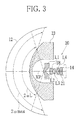
FIG. 3 is a cross-sectional view of the capsule endoscope of the present invention used for explainingmathematical expression 1 tomathematical expression 3. -
FIG. 4A is a diagram illustrating a plurality of circles provided on a subject of concave sphere, andFIGS. 4B to 4E are diagrams each illustrating an image capturing the plurality of circles ofFIG. 4A . -
FIG. 5 is a cross-sectional view illustrating configurations of imaging lens and transparent cover according toEmbodiment 1. -
FIG. 6 is an aberration diagram of the imaging lens and transparent cover according toEmbodiment 1. -
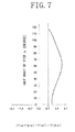
FIG. 7 is a graph illustrating distortion of the imaging lens and transparent cover according toEmbodiment 1. -
FIG. 8 is a cross-sectional view illustrating configurations of imaging lens and transparent cover according toEmbodiment 2. -
FIG. 9 is an aberration diagram of the imaging lens and transparent cover according toEmbodiment 2. -
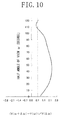
FIG. 10 is a graph illustrating distortion of the imaging lens and transparent cover according toEmbodiment 2. - As shown in
FIG. 1 , acapsule endoscope 10 is formed in such a size that it can be swallowed by a patient with ease, and captures images inside the stomach or intestines during the period from being swallowed until excretion from the body at constant time intervals. In this embodiment, asubject 12 of concave sphere is explained as a subject to be captured with thecapsule endoscope 10. Note that the shape of the subject is not limited to the concave sphere but may be in other concave curved forms. - As shown in
FIG. 1 and FIG. 2 illustrating thecapsule endoscope 10 viewed from a direction which is rotated 90 degrees clockwise fromFIG. 1 , thecapsule endoscope 10 is provided with acapsule 13, animage sensor 14, animaging lens 20, and acover glass 21. Thecapsule 13 has acapsule body 22 and atransparent cover 23. Thecapsule body 22 is formed hollow, and has an opening 22b at itsend 22a. Theimaging lens 20 is provided such that a part thereof is positioned inside thecapsule body 22 and the rest is protruded from the opening 22b. Thetransparent cover 23 is formed into a dome shape, and is attached to theend 22a of thecapsule body 22 to cover theimaging lens 20 protruded from the opening 22b. Depending on the design conditions of the lens, the whole imaging lens may be protruded from the opening of the capsule body, or the whole imaging lens may be provided inside the capsule body. - The
imaging lens 20 andtransparent cover 23 have optical power for forming an image from light from thesubject 12 on theimage sensor 14. On the other hand, thecover glass 21 transmits the light from thesubject 12 without refracting it, which means has no optical power like theimaging lens 20 andtransparent cover 23. The material of thetransparent cover 23 may be the same as theimaging lens 20 and not particularly limited. - In addition to the
image sensor 14, a battery (not shown) for driving theimage sensor 14, an antenna (not shown) for sending the image captured with theimage sensor 14 to image receivers (not shown) attached to the patient, and the like are stored inside thecapsule body 22. - As shown in
FIG. 3 , theimaging lens 20 is constituted of a first lens L1, a second lens L2, an aperture stop S8, a third lens L3, and a fourth lens L4, arranged in this order from thesubject 12 side. Thetransparent cover 23 is provided between thesubject 12 and the first lens L1. - Here, the
imaging lens 20 andtransparent cover 23 are designed to satisfy the following mathematical expression 1:
transparent cover 23 is defined as fD and a focal length of thewhole imaging lens 20 is defined as fL, - When the
imaging lens 20 andtransparent cover 23 satisfy themathematical expression 1 while providing thetransparent cover 23 with the optical power of forming an image from the light from thesubject 12 on theimage sensor 14, an angle of view is widened more. Owing to this, even a lesion which is situated at the periphery of thetransparent cover 23 can also be surely captured. Even though the angle of view is widened, an aberration caused by widening the angle of view is sufficiently corrected, and therefore a clear image with no distortion or blurring can be obtained. When |fD|/fL is more than 70, the refractive power of thetransparent cover 23 becomes small. As a result, the wide angle of view has to be achieved only with theimaging lens 20, which makes it difficult to correct aberrations. - In addition, the
imaging lens 20 andtransparent cover 23 are designed to satisfy the following mathematical expression 2:
imaging lens 20 andtransparent cover 23 as a whole, and 2ωL is a maximum angle of view of theimaging lens 20 only. - When the
imaging lens 20 andtransparent cover 23 satisfy themathematical expression 2 while providing thetransparent cover 23 with the optical power of forming an image from the light from the subject 12 on theimage sensor 14, the lesion situated within the angle of view of theimaging lens 20 andtransparent cover 23 as a whole can be surely captured, even if the lesion is not situated within the angle of view of theimaging lens 20. Even though the angle of view is widened, an aberration caused by widening the angle of view is sufficiently corrected, and therefore a clear image with no distortion or blurring can be obtained on theimage sensor 14. When 2ωmax-2ωL is less than 2.5, the refractive power of thetransparent cover 23 becomes small. As a result, the wide angle of view has to be achieved only with theimaging lens 20, which makes it difficult to correct aberrations. - Moreover, the
imaging lens 20 andtransparent cover 23 are designed to satisfy the following mathematical expression 3:
- When the
imaging lens 20 andtransparent cover 23 satisfy themathematical expression 3, an angle of view is widened more. Owing to this, even a lesion which is situated at the periphery of thetransparent cover 23 can also be surely captured. Even though the angle of view is widened, an aberration caused by widening the angle of view is sufficiently corrected, and therefore a clear image with no distortion or blurring can be obtained even when the lesion situated at the periphery of thetransparent cover 23 is captured. - Further, the
imaging lens 20 andtransparent cover 23 are designed to satisfy the following mathematical expression 4:
mathematical expression 4 may be satisfied under the condition that the angle of view is 105° or less. - In the
mathematical expression 4, "Y (ω+Δω) -Y (ω)" indicates a difference between an image height Y (ω+Δω) at an angle of view ω+Δω, in which a slight change, such as from ω to Δω, is made in the angle of view, and the image height Y(ω)) at the angle of view ω. Moreover, "Y(Δω)" in themathematical expression 4 indicates a difference Y(0+Δω)-Y(0) between the image height Y(Δω) at the angle of view Δω, in which a slight change, such as from 0° to Δω, is made in the angle of view, and the image height Y(0) at the angle of view 0°. Since Y(0) is equal to 0, Y(0+Δω)-Y(0) is equal to Y(Δω). Accordingly, the part "(Y(ω+Δω)-Y(ω))/Y(Δω)" in themathematical expression 4 represents a degree of distortion at periphery area of the image with respect to a center area of the image. - Here, four combinations of the
imaging lens 20 andtransparent cover 23 are designed such that (Y(ω+Δω)-Y(ω))/Y(Δω) respectively is 1.0, 0.7, 0.5 and 0.3. The image captured with each combination of the imaging lens and transparent cover is evaluated in view of degree of distortion. In the evaluation, as shown inFIG. 4A , circles 30a to 30e with a radius of r, 2r, 3r, 4r, and 5r, respectively are provided concentrically on the subject 12 of concave sphere at regular intervals of distance r. Then, the subject 12 with thecircles 30a to 30e is captured using each pair of the imaging lens and transparent cover. On the captured image, distance between the adjacent circles is compared between the periphery area and the center area of the image. The degree of distortion at the periphery area of the image is evaluated by checking how much the distance between the circles contracted at the periphery area as compared to that at the center area. -
FIG. 4B shows the image captured with a combination of theimaging lens 20 andtransparent cover 23 which satisfies the following condition: (Y(ω+Δω)-Y(ω))/Y(Δω) = 1.0. As can be seen from the image, the distance interval between the adjacent circles on the image is equal to the distance r which is the distance between the adjacent circles of thecircles 30a to 30e provided on the subject 12. Since the distance between the adjacent circles at the center area of the image is same as the distance between the adjacent circles at the periphery area of the image, the distortion does not occur at the periphery area of the image. Accordingly, when an image inside the body of the patient is captured with thecapsule endoscope 10 provided with theimaging lens 20 andtransparent cover 23 configured as such, the lesion appearing at the periphery area in the image is not distorted, and therefore the lesion can be surely found. -
FIG. 4C shows the image captured with a combination of theimaging lens 20 andtransparent cover 23 which satisfies the following condition: (Y(ω+Δω)-Y(ω))/Y(Δω) = 0.7. As can be seen from the image, the distance between the adjacent circles at the center area of the image is larger than the distance r, while the distance between the adjacent circles at the periphery area of the image is smaller than the distance r. That is, the distance between the adjacent circles is smaller at the periphery area of the image as compared to the center area of the image, however, the contraction in the distance between the adjacent circles at the periphery area is not so distinguishable. Accordingly, when an image inside the body of the patient is captured with thecapsule endoscope 10 provided with theimaging lens 20 configured as such, the lesion appearing at the periphery area in the image is distorted to the extent that the distortion may be or may not be barely negligible in the diagnosis using the image. -
FIG. 4D shows the image captured with a combination of theimaging lens 20 andtransparent cover 23 which satisfies the following condition: (Y(ω+Δω)-Y(ω))/Y(Δω) = 0.5. As can be seen from the image, the distance between the adjacent circles is smaller at the periphery area of the image as compared to the distance between the adjacent circles at the center area of the image, and the contraction in the distance between the adjacent circles at the periphery area of the image is distinguishable. Hence, it is known that the distortion occurred at the periphery area of the image. Accordingly, when an image inside the body of the patient is captured with thecapsule endoscope 10 provided with theimaging lens 20 andtransparent cover 23 configured as such, the periphery area in the image is distorted, and therefore the lesion may be overlooked. -
FIG. 4E shows the image captured with a combination of theimaging lens 20 andtransparent cover 23 which satisfies the following condition: (Y(ω)+Δω)-Y((ω))/Y(Δω) = 0.3. As can be seen from the image, the distance between the adjacent circles is extremely smaller at the periphery area of the image as compared to the distance between the adjacent circles at the center area of the image, and the contraction in the distance between the adjacent circles at the periphery area of the image is conspicuous at a glance of the image. Hence, it is known that the distortion occurred at the periphery area of the image. Accordingly, when an image inside the body of the patient is captured with the capsule endoscope provided with theimaging lens 20 andtransparent cover 23 configured as such, the periphery area in the image is extremely distorted, and therefore the lesion will most likely be overlooked. - In view of the above results, the distortion at the periphery area of the image can be suppressed by designing the
imaging lens 20 andtransparent cover 23 to satisfy the following condition: (Y(ω+Δω)-Y(ω))/Y(Δω) > 0.7. When the condition is satisfied, the lesion, even if it appears at the periphery area of the image, will not be distorted to the extent that it is overlooked, and therefore the lesion can be surely found. Note that the amount calculated by the following condition: (Y(ω+Δω)-Y(ω))/Y(Δω) is preferably more than 0.7 and less than 1.3, and more preferably more than 0.8 and less than 1.2. - In addition, since the
imaging lens 20 is constituted of four lenses: the first to fourth lenses, the angle of view is widened more, and therefore the lesion situated at the periphery of thetransparent cover 23 can be captured. Even though the angle of view is widened, an aberration caused by widening the angle of view is sufficiently corrected, and therefore a clear image with no distortion or blurring can be obtained in capturing the lesion situated at the periphery of thetransparent cover 23. Note that if the imaging lens is constituted of five lenses of first to fifth lenses, the same effect can be obtained as the imaging lens constituted of four lenses. - In the above embodiment, the capsule endoscope whose position and orientation inside the body of the patient are not controlled is used for explanation, however, the present invention is not limited to this. The present invention is also applicable to capsule endoscopes whose position and orientation are controllable inside the patient's body.
- Hereinafter, the present invention is explained more in detail by showing concrete numerical values in the following Embodiments 1 and 2 as to the imaging lens and transparent cover mounted on the capsule endoscope.
- As shown in
FIG. 5 , theimaging lens 20 inEmbodiment 1 includes four lenses of first lens L1 to fourth lens L4, and an aperture stop S8. Inside thecapsule 13, the first lens L1, second lens L2, aperture stop S8, third lens L3, and fourth lens L4 are arranged in this order from the side of the subject 12 of concave sphere. Thetransparent cover 23 is disposed between the subject 12 and the first lens L1. - Surfaces of the subject 12, the
transparent cover 23, and theimaging lens 20 are represented by Si. That is, the surface of the subject 12 is S1, the surface of thetransparent cover 23 on the subject 12 side (hereinafter referred to as the "subject side") is S2, the surface of thetransparent cover 23 on theimage sensor 14 side (hereinafter referred to as the "image side") is S3, the surface of the first lens L1 on the subject side is S4, the surface of the first lens L1 on the image side is S5, the surface of the second lens L2 on the subject side is S6, the surface of the second lens L2 on the image side is S7, the aperture stop is S8, the surface of the third lens L3 on the subject side is S9, the surface of the third lens L2 on the image side is S10, the surface of the fourth lens L4 on the subject side is S11, the surface of the fourth lens L4 on the image side is S12, the surface of thecover glass 21 on the subject side is S13, and the surface of thecover glass 21 on the image side is S14. The surface S14 coincides with an imaging surface of theimage sensor 14. - In addition, a distance between the surface Si and the surface S(i+1) (hereinafter referred to as surface separation) in a direction of an optical axis of the
imaging lens 20 is represented by Di. That is, a surface separation between the surfaces S1 and S2 is D1, a surface separation between the surfaces S2 and S3 is D2, a surface separation between the surfaces S3 and S4 is D3, a surface separation between the surfaces S4 and S5 is D4, a surface separation between the surfaces S5 and S6 is D5, a surface separation between the surfaces S6 and S7 is D6, a surface separation between the surfaces S7 and S8 is D7, a surface separation between the surfaces S8 and S9 is D8, a surface separation between the surfaces S9 and S10 is D9, a surface separation between the surfaces S10 and S11 is D10, surface separation between the surfaces S11 and S12 is D11, a surface separation between the surfaces S12 and S43 is D12, and a surface separation between the surfaces S13 and S14 is D13. - The
imaging lens 20 andtransparent cover 23 are designed based on lens data shown in Table 1 below.[Table 1] fL=1.5 fD=-24.7 Fno=2.0 |fD|/fL=16.5 2ωmax=233° 2ωL=159° 2ωmax-2ωL74° SURFACE CURVATURE SURFACE Nd νd RADIUS SEPARATION OBJ 37.7888 18.8944 2 31.1292 1.8894 1.58600 55.0 3 9.6958 9.4470 4* 2.8769 1.6986 1.53039 55.2 5* 0.8065 3.0030 6* 5.4945 2.5758 1.63178 23.2 7* -5.1295 0.2486 STOP ∞ .3526 9* -8.3170 1.7502 1.54378 55.7 10* -2.7705 0.3117 11* 5.0793 1.7364 1.54378 55.7 12* -7.4451 0.6228 13 ∞ 1.8894 1.5592 53.9 14 ∞ 0.0000 IMG ∞ - In Table 1, "OBJ" represents the subject 12 of concave sphere, "STOP" represents the aperture stop S8, "IMG" represents the
image sensor 14, "CURVATURE RADIUS" represents the curvature radius (mm) of each surface Si, "SURFACE SEPARATION" represents the distance Di between the surfaces Si and S(i+1) (mm), "Nd" represents refractive index for d-line (wavelength of 587. 6 nm), "νd" represents Abbe's number, "fL" represents the focal length of theimaging lens 20 as a whole, "fD" represents the focal length of thetransparent cover 23, "Fno" represents F number of theimaging lens 20, "2ωmax" represents the maximum angle of view of theimaging lens 20 andtransparent cover 23 as a whole, and "2ωL" represents the maximum angle of view of theimaging lens 20 only. - In Table 1, a symbol "*" in the column of the surface number indicates an aspheric surface. That is, the surfaces S4 and S5 of the first lens L1, the surfaces S6 and S7 of the second lens L2, the surfaces S9 and S10 of the third lens L3, and the surfaces S11 and S12 of the fourth lens L4 are the aspheric surfaces. These aspheric surfaces can be numerically represented by the following
mathematical expression 5 with use of a curvature (reciprocal of paraxial curvature radius R) c, a conic constant K, a distance from the optical axis ρ ( ρ2=x2+y2), and an aspherical degree of ith number. The conic constant K and an aspherical constant Ai of the surfaces S4, S5, S6, S7, S9, S10, 511, and S12 are respectively shown in Table 2. Note that the citation of the lens data and themathematical expression 5 for determining the shape of the aspheric surface are the same inEmbodiment 2 which is described later.
[Table 2] SURFACE K A3 A4 A5 4 -1.0000 -4.2355E-02 9.1919E-04 3.3623E-04 5 -1.0000 -1.4101E-01 3.6825E-02 -7.8345E-03 6 -1.0000 -1.2412E-02 3.2105E-02 -3.1943E-02 7 -1.0000 -2.1957E-03 5.7038E-03 1.4382E-02 9 -1.0000 1.7300E-02 -5.4558E-02 -3.3348E-02 10 -1.0000 2.0559E-02 -2.8751E-02 -1.9351E-02 11 -1.0000 5.4084E-02 -5.5518E-02 -3.8369E-03 12 -1.0000 3.9520E-02 4.5198E-02 -2.7955E-02 SURFACE A6 A7 A8 A9 4 2.2977E-05 1.0368E-07 -6.3350E-07 -6.9338E-08 5 -2.3283E-03 8.3065E-05 1.7706E-04 5.3216E-05 6 5.9239E-03 3.5639E-03 -4.8005E-04 -5.6797E-04 7 -4.2683E-02 2.4108E-02 1.1584E-02 -9.3655E-03 9 1.1820E-01 1.5097E-02 -1.9710E-01 1.6490E-01 10 4.2818E-03 6.7242E-03 1.3140E-C3 -1.6786E-03 11 8.6023E-03 -1.1303E-03 -7.2265E-04 2.6764E-04 12 -5.1380E-03 2.1621E-03 5.9020E-04 4.8906E-06 SURFACE A10 A11 A12 A13 4 -5.7927E-09 3.1473E-11 1.9307E-10 3.2478E-11 5 1.4080E-05 6.0631E-07 -1.4249E-06 -8.0330E-07 6 5.1764E-06 2.1187E-05 -1.2258E-05 1.2964E-05 7 -7.6449E-03 8.0531E-03 -2.0980E-03 6.2356E-05 9 -3.8344E-02 -4.5310E-03 -7.4578E-04 5.6381E-04 10 -1.4204E-04 -1.2595E-04 1.5921E-05 6.7900E-05 11 1.1191E-04 -1.3653E-05 -5.7751E-05 6.4909E-06 12 -6.5258E-06 -9.7581E-06 -5.6170E-06 -2.6881E-06 SURFACE A14 A15 A16 A17 4 5.4560E-12 8.1138E-13 -1.3131E-13 -3.0354E-14 5 -8.7674E-08 2.5035E-08 -1.3454E-09 3.3524E-09 6 -1.1297E-06 -6.9191E-07 1.0631E-07 3.1486E-10 7 7.7467E-06 5.8725E-06 5.6415E-08 3.7608E-10 9 2.5615E-04 -5.1940E-15 -4.4301E-13 -1.1725E-14 10 -8.2271E-06 -6.8705E-07 -4.8595E-08 -7.2448E-14 11 6.9417E-06 -1.1795E-06 -3.1032E-08 -1.2949E-10 12 1.7655E-06 -2.4612E-08 -4.9367E-08 6.4750E-09 SURFACE A18 A19 A20 4 -3.5511E-15 3.0064E-16 5.8582E-17 5 2.5060E-11 -1.2689E-18 5.3334E-20 6 -3.5164E-16 4.6343E-17 4.8975E-20 7 -7.0551E-16 -8.1997E-18 -2.1615E-19 9 -2.7644E-16 -7.3149E-18 -1.9357E-19 10 -1.1706E-16 -8.2110E-18 -2.1639E-19 11 4.9078E-12 1.2020E-17 -2.1434E-18 12 -6.8408E-11 -7.6951E-20 -2.9998E-19 -
FIG. 6 shows spherical aberration, astigmatism, and chromatic aberration of magnification under the configuration that thetransparent cover 23 is disposed on the subject side of theimaging lens 20 and thecover glass 21 is disposed on the image side of theimaging lens 20. In the spherical aberration, d-line (wavelength of 587.6 nm) is shown with a solid line, F-lie (wavelength of 486.13 nm) is shown with a first dashed line, and C-line (wavelength of 656.27 nm) is shown with a second dashed line which is a longer dashed line than the first dashed line. The astigmatism in sagittal direction is shown with a solid line and the astigmatism in tangential direction is shown with the first dashed line. In the chromatic aberration of magnification, F-line is shown with the first dashed line and C-line is shown with the second dashed line which is a longer dashed line than the first dashed line. Note that the lines showing the spherical aberration, astigmatism, and chromatic aberration of magnification, respectively are the same inEmbodiment 2 which is described later. - In
Embodiment 1, the focal length fD of thetransparent cover 23 is -24.7 mm and the focal length fL of theimaging lens 20 is 1.5 mm. Accordingly, the value of |fD|/fL is 16.5 which is within the range of themathematical expression 1. Moreover, since the amount of 2ωmax is 233°, which is within the range of themathematical expression 3, and the amount of 2ωL is 159°, the value of 2ωmax-2ωL is 74° which is within the range of themathematical expression 2. Owing to this, the angle of view is widened more, and therefore even the lesion situated at the periphery of thetransparent cover 23 can be captured. As shown inFIG. 6 , the spherical aberration, astigmatism, and chromatic aberration of magnification are sufficiently corrected even if the angle of view is widened. Therefore, a clear image can be obtained even when the lesion situated at the periphery of thetransparent cover 23 is captured. - As shown in
FIG. 7 , the value of (Y(ω+Δω)-Y((ω))/Y(Δω)) is more than 0.7 over the entire range of the half angle of view ω, and therefore theimaging lens 20 andtransparent cover 23 are within the range of themathematical expression 4. Owing to this, the distortion occurring at the periphery area of the image can be suppressed. As a result, the lesion appearing at the periphery of the image is not so distorted to the extent that it is overlooked, and therefore the lesion can be surely found. - As shown in
FIG. 8 , animaging lens 30 inEmbodiment 2 includes five lenses of first lens L1 to fifth lens L5, and an aperture stop 56. Inside thecapsule 13, the first lens L1, the aperture stop S6, the second lens L2, the third lens L3, the fourth lens L4, and the fifth lens L5 are arranged in this order from the side of the subject 12 of concave sphere. The third lens L3 and the fourth lens L4 constitutes a laminated lens. Thetransparent cover 23 is disposed between the subject 12 and the first lens L1. - Similarly to
Embodiment 1, surfaces of the subject 12, thetransparent cover 23, and theimaging lens 30 are represented by Si. That is, the surface of the subject 12 is S1, the surface of thetransparent cover 23 on the subject side is S2, the surface of thetransparent cover 23 on the image side is S3, the surface of the first lens L1 on the subject side is S4, the surface of the first lens L1 on the image side is S5, the aperture stop is S6, the surface of the second lens L2 on the subject side is S7, the surface of the second lens L2 on the image side is S8, the surface of the third lens L3 on the subject side is S9, the laminated surface of the third lens L3 is S10, the surface of the fourth lens L4 on the image side is S11, the surface of the fifth lens L5 of the subject side is S12, the surface of the fifth lens L5 of the image side is S13, the surface of thecover glass 21 on the subject side is S14, and surface of thecover glass 21 on the image side is S15. The surface S15 coincides with the imaging surface of theimage sensor 14. - In addition, a distance between the surface Si and the surface S(i+1) (surface separation) in a direction of an optical axis of the
imaging lens 30 is represented by Di. That is, a surface separation between the surfaces S1 and S2 is D1, a surface separation between the surfaces S2 and S3 is D2, a surface separation between the surfaces S3 and S4 is D3, a surface separation between the surfaces S4 and S5 is D4, a surface separation between the surfaces S5 and S6 is D5, a surface separation between the surfaces S6 and S7 is D6, a surface separation between the surfaces S7 and S8 is D7, a surface separation between the surfaces S8 and S9 is D8, a surface separation between the surfaces S9 and S10 is D9, a surface separation between the surfaces S10 and S11 is D10, a surface separation between the surfaces S11 and S12 is D11, a surface separation between the surfaces S12 and S13 is D12, a surface separation between the surfaces S13 and S14 is D13, and a surface separation between the surfaces S14 and S15 is D14. - The
imaging lens 30 is designed based on lens data shown in Table 3 below.[Table 3] fL=1.6 fD=-19.3 Fno=2.0 |fD|/fL=12.1 2ωmax=243° 2ωL=147° 2ωmax-2ωL=96° SURFACE CURVATURE RADIUS SURFACE SEPARATION Nd νd OBJ 45.8616 22.9308 2 31.7901 2.2931 1.58600 55.0 3 8.1454 8.3514 4* 11.8912 2.4820 1.53039 55.2 5* 1.2502 3.3004 STOP ∞ 0.8239 7* 7.8522 3.1590 1.53039 55.2 8* -2.8809 0.7210 9 -8.3637 4.5066 1.92286 18.9 10 8.9747 3.8677 1.72916 54.7 11 -8.4625 0.9584 12* 10.0245 4.3967 1.53039 55.2 13* -2.5414 0.8537 14 ∞ 2.2931 1.55920 53.9 15 ∞ 0.0000 IMG ∞ - In Table 3, a symbol "*" in the column of the surface number indicates an aspheric surface. That is, the surfaces S4 and S5 of the first lens L1, the surfaces S7 and S8 of the second lens L2, and the surfaces S12 and S13 of the fifth lens L5 are the aspheric surfaces. The conic constant K and the aspherical constant Ai of the surfaces S4, S5, S7, S8, S12, and S13 are shown in Table 4.
[Table 4] SURFACE K A3 A4 A5 4 -1.0000 -4.1211E-03 -2.0789E-03 1.6278E-04 5 -1.0000 -2.7379E-01 1.9759E-01 -3.6734E-02 7 -1.0000 -4.2260E-03 1.1042E-03 -3.9770E-03 8 -1.0000 -6.3453E-03 8.4601E-03 -3.5200E-03 12 -1.0000 -5.6968E-03 7.0057E-03 -1.0109E-03 13 -1.0000 5.5962E-02 1.2624E-03 -2.0759E-04 SURFACE A6 A7 A8 A9 4 3.5252E-05 3.1255E-06 -3.6575E-08 -7.1605E-08 5 -1.7317E-02 5.5113E-04 2.9509E-03 9.0608E-04 7 -2.8140E-04 1.2269E-03 4.4777E-05 -1.1980E-04 8 1.7387E-04 1.5704E-05 2.9431E-05 -9.5373E-06 12 -2.9044E-05 1.4767E-05 1.4667E-06 -5.4865E-08 13 -8.2208E-05 -1.6629E-05 -2.3223E-06 -7.7639E-08 SURFACE A10 A11 A12 A13 4 -1.5083E-08 -2.3358E-09 -8.2106E-11 3.8892E-11 5 -2.2020E-04 -2.5128E-04 4.3420E-05 8.4058E-06 7 -7.9379E-05 -5.4175E-06 4.4506E-05 -1.1955E-05 8 -2.7177E-06 -1.7337E-07 -8.1997E-08 2.3964E-07 12 -2.8382E-08 -5.5487E-09 -8.4172E-10 -7.1694E-11 13 8.9311E-08 -3.6021E-10 4.8163E-10 2.5385E-11 SURFACE A14 A15 A16 A17 4 1.1935E-11 1.8169E-12 -1.0312E-13 -1.1082E-13 5 -1.3497E-06 -6.2400E-09 1.0999E-21 2.3984E-23 7 -7.1950E-08 1.0389E-08 -9.3374E-12 1.6927E-13 8 4.9096E-08 -1.5338E-08 -1.1340E-09 -5.0901E-12 12 2.3969E-12 2.6410E-12 6.9906E-13 1.1607E-13 13 3.9097E-12 1.8067E-12 5.7627E-13 1.4867E-13 SURFACE A18 A19 A20 4 -7.8781E-15 3.5945E-15 -2.6606E-17 5 -1.6746E-21 -4.8517E-21 -1.0594E-22 7 6.1835E-22 8.7018E-24 4.2216E-26 8 8.9804E-15 1.1404E-26 2.9399E-25 12 -6.8918E-15 -2.6120E-15 3.4009E-17 13 5.3352E-14 -1.2354E-14 -4.6038E-16 -
FIG. 9 shows spherical aberration, astigmatism, and chromatic aberration of magnification under the configuration that thetransparent cover 23 is disposed on the subject side of theimaging lens 30 and thecover glass 21 is disposed on the image side of theimaging lens 30. - In
Embodiment 2, the focal length fD of thetransparent cover 23 is -19.3 mm and the focal length fL of theimaging lens 30 is 1. 6 mm. Accordingly, the value of |fD|/fL is 12.1 which is within the range of themathematical expression 1. Moreover, since the amount of 2ωmax is 243°, which is within the range of themathematical expression 3, and the amount of 2ωL is 147°, the value of 2ωmax-2ωL is 96° which is within the range of themathematical expression 2. Owing to this, the angle of view is widened more, and therefore even the lesion situated at the periphery of thetransparent cover 23 can be captured. As shown inFIG. 9 , the spherical aberration, astigmatism, and chromatic aberration of magnification are sufficiently corrected even if the angle of view is widened. Therefore, a clear image can be obtained even when the lesion situated at the periphery of thetransparent cover 23 is captured. - As shown in
FIG. 10 , the value of (Y(ω+Δω)-Y(ω))/Y(Δω) is more than 0.7 over the almost entire range of the half angle of view ω. Owing to this, the distortion can be suppressed. -
- 10:
- CAPSULE ENDOSCOPE
- 20:
- IMAGING LENS
- 23:
- TRANSPARENT COVER
- L1:
- FIRST LENS
- L2:
- SECOND LENS
- L3:
- THIRD LENS
- L4:
- FOURTH LENS
Claims (11)
- A capsule endoscope comprising a hollow capsule body having an opening at its end, an imaging optical system provided inside said capsule body or provided to protrude from said opening of said capsule body, and a transparent cover attached to said end of said capsule body to cover said imaging optical system, wherein said transparent cover and said imaging optical system satisfying the following condition for imaging the inside of a body cavity of a patient:

where fD is a focal length of said transparent cover, and fL is a focal length of said imaging optical system. - The capsule endoscope according to claim 1 comprising a hollow capsule body having an opening at its end, an imaging optical system provided inside said capsule body or provided to protrude from said opening of said capsule body, and a transparent cover attached to said end of said capsule body to cover said imaging optical system, wherein said transparent cover and said imaging optical system satisfying the following condition for imaging the inside of a body cavity of a patient:

where 2ωmax is a maximum angle of view of said imaging optical system and said transparent cover as a whole, and 2ωL is a maximum angle of view of said imaging optical system only. - The capsule endoscope according to claim 1 or 2, wherein the following condition is satisfied:

where 2ωmax is a maximum angle of view of said imaging optical system and said transparent cover as a whole. - The capsule endoscope according to any one of claims 1 to 3, wherein the following condition is satisfied:

where Y(ω)) is an image height at an arbitrary angle of view ω, and Δω is an amount of slight change in said arbitrary angle of view ω. - The capsule endoscope according to any one of claims 1 to 4, wherein said imaging optical system is constituted of four lenses.
- The capsule endoscope according to any one of claims 1 to 4, wherein said imaging optical system is constituted of five lenses.
- A capsule endoscope comprising a hollow capsule body having an opening at its end, an imaging optical system provided inside said capsule body or provided to protrude from said opening of said capsule body, and a transparent cover attached to said end of said capsule body to cover said imaging optical system, wherein said transparent cover and said imaging optical system satisfying the following condition for imaging the inside of a body cavity of a patient:

where 2ωmax is a maximum angle of view of said imaging optical system and said transparent cover as a whole, and 2ωL is a maximum angle of view of said imaging optical system only. - The capsule endoscope according to claim 7, wherein the following condition is satisfied:

where 2ωmax is a maximum angle of view of said imaging optical system and said transparent cover as a whole. - The capsule endoscope according to claim 7 or 8, wherein the following condition is satisfied:

where Y(ω) is an image height at an arbitrary angle of view ω, and Δω is an amount of slight change in said arbitrary angle of view ω. - The capsule endoscope according to any one of claims 7 to 9, wherein said imaging optical system is constituted of four lenses.
- The capsule endoscope according to any one of claims 7 to 9, wherein said imaging optical system is constituted of five lenses.
Applications Claiming Priority (2)
| Application Number | Priority Date | Filing Date | Title |
|---|---|---|---|
| JP2009071919A JP5441465B2 (en) | 2009-03-24 | 2009-03-24 | Capsule endoscope |
| PCT/JP2010/055141 WO2010110350A1 (en) | 2009-03-24 | 2010-03-24 | Capsule endoscope |
Publications (2)
| Publication Number | Publication Date |
|---|---|
| EP2413177A1 true EP2413177A1 (en) | 2012-02-01 |
| EP2413177A4 EP2413177A4 (en) | 2014-07-30 |
Family
ID=42781043
Family Applications (1)
| Application Number | Title | Priority Date | Filing Date |
|---|---|---|---|
| EP10756146.6A Withdrawn EP2413177A4 (en) | 2009-03-24 | 2010-03-24 | Capsule endoscope |
Country Status (6)
| Country | Link |
|---|---|
| US (1) | US8526112B2 (en) |
| EP (1) | EP2413177A4 (en) |
| JP (1) | JP5441465B2 (en) |
| KR (1) | KR20110137781A (en) |
| CN (1) | CN102362208B (en) |
| WO (1) | WO2010110350A1 (en) |
Families Citing this family (13)
| Publication number | Priority date | Publication date | Assignee | Title |
|---|---|---|---|---|
| JP2015011050A (en) * | 2013-06-26 | 2015-01-19 | 京セラ株式会社 | Imaging lens and imaging device |
| CN105636959B (en) * | 2013-10-08 | 2019-10-18 | 默克专利有限公司 | Materials for Electronic Devices |
| KR101548646B1 (en) * | 2014-01-21 | 2015-09-01 | 가톨릭관동대학교산학협력단 | Trans-Platform Apparatus and Their Uses |
| US9876992B2 (en) | 2014-04-30 | 2018-01-23 | Panasonic Intellectual Property Management Co., Ltd. | Imaging apparatus and distance measuring apparatus using the same |
| JP6356561B2 (en) * | 2014-09-26 | 2018-07-11 | 京セラ株式会社 | Imaging lens and imaging apparatus |
| WO2018097287A1 (en) * | 2016-11-28 | 2018-05-31 | コニカミノルタ株式会社 | Imaging optical system, lens unit, and imaging device |
| TWI724190B (en) | 2017-06-23 | 2021-04-11 | 佳能企業股份有限公司 | Optical lens and electronic device using the same |
| CN109143534B (en) * | 2017-06-28 | 2022-02-08 | 佳能企业股份有限公司 | Optical lens and electronic device using same |
| US11160686B2 (en) * | 2017-12-12 | 2021-11-02 | Alcon Inc. | Multi-core fiber for a multi-spot laser probe |
| WO2019123753A1 (en) * | 2017-12-21 | 2019-06-27 | オリンパス株式会社 | Capsule endoscope |
| CN108508590A (en) * | 2018-04-19 | 2018-09-07 | 深圳市都乐精密制造有限公司 | Wide-angle capsule lens are peeped in medical |
| WO2020110233A1 (en) * | 2018-11-28 | 2020-06-04 | オリンパス株式会社 | Set of negative meniscus lenses, wide-angle optical system, imaging device, and projection device |
| CN113974531A (en) * | 2021-10-07 | 2022-01-28 | 江西高瑞光电股份有限公司 | A medical capsule wide-angle endoscope lens |
Family Cites Families (15)
| Publication number | Priority date | Publication date | Assignee | Title |
|---|---|---|---|---|
| JP2002116491A (en) * | 2000-10-05 | 2002-04-19 | Inon:Kk | Amphibian wide conversion lens attached/dedicated to waterproof camera housing |
| US7153259B2 (en) | 2003-09-01 | 2006-12-26 | Olympus Corporation | Capsule type endoscope |
| JP5178991B2 (en) * | 2004-08-27 | 2013-04-10 | オリンパス株式会社 | Capsule endoscope |
| JP4128505B2 (en) * | 2003-09-05 | 2008-07-30 | オリンパス株式会社 | Capsule endoscope |
| JP4128504B2 (en) | 2003-09-05 | 2008-07-30 | オリンパス株式会社 | Capsule endoscope |
| JP4516475B2 (en) * | 2005-04-27 | 2010-08-04 | オリンパスメディカルシステムズ株式会社 | Imaging optical system for an endoscope having a substantially spherical observation window |
| US7869125B2 (en) * | 2006-04-17 | 2011-01-11 | Raytheon Company | Multi-magnification viewing and aiming scope |
| JP4674906B2 (en) * | 2006-07-03 | 2011-04-20 | オリンパス株式会社 | Optical system |
| JP5214161B2 (en) * | 2006-07-10 | 2013-06-19 | オリンパス株式会社 | Transmission optical element and optical system using the same |
| JP2008197541A (en) * | 2007-02-15 | 2008-08-28 | Nikon Corp | Imaging optical system, optical apparatus, and imaging apparatus |
| CN201039978Y (en) * | 2007-04-17 | 2008-03-26 | 深圳市一体医疗科技有限公司 | Capsule endoscope |
| JP2008309860A (en) | 2007-06-12 | 2008-12-25 | Olympus Corp | Optical system and endoscope using the same |
| EP2172798B1 (en) * | 2007-07-09 | 2016-01-13 | Olympus Corp. | Optical element, optical system equipped with same and endoscope using same |
| CN100582855C (en) * | 2007-08-23 | 2010-01-20 | 鸿富锦精密工业(深圳)有限公司 | Endoscopy lens and endoscopy device |
| JP2009061097A (en) * | 2007-09-06 | 2009-03-26 | Olympus Medical Systems Corp | Capsule endoscope |
-
2009
- 2009-03-24 JP JP2009071919A patent/JP5441465B2/en not_active Expired - Fee Related
-
2010
- 2010-03-24 US US13/259,192 patent/US8526112B2/en not_active Expired - Fee Related
- 2010-03-24 EP EP10756146.6A patent/EP2413177A4/en not_active Withdrawn
- 2010-03-24 CN CN201080013174.1A patent/CN102362208B/en not_active Expired - Fee Related
- 2010-03-24 WO PCT/JP2010/055141 patent/WO2010110350A1/en not_active Ceased
- 2010-03-24 KR KR1020117022080A patent/KR20110137781A/en not_active Ceased
Also Published As
| Publication number | Publication date |
|---|---|
| KR20110137781A (en) | 2011-12-23 |
| JP2010220844A (en) | 2010-10-07 |
| US20120022327A1 (en) | 2012-01-26 |
| US8526112B2 (en) | 2013-09-03 |
| WO2010110350A1 (en) | 2010-09-30 |
| EP2413177A4 (en) | 2014-07-30 |
| CN102362208B (en) | 2014-06-04 |
| JP5441465B2 (en) | 2014-03-12 |
| CN102362208A (en) | 2012-02-22 |
Similar Documents
| Publication | Publication Date | Title |
|---|---|---|
| EP2413177A1 (en) | Capsule endoscope | |
| EP2413176A1 (en) | Image-capturing optical system for capsule endoscope | |
| US8243129B2 (en) | Objective lens and endoscope apparatus | |
| JP5635678B2 (en) | Imaging lens and imaging apparatus | |
| US9442283B2 (en) | Endoscopic objective lens and endoscope | |
| JP5324321B2 (en) | Endoscope objective lens and endoscope | |
| EP3037858A1 (en) | Endoscope objective optical system | |
| EP2299306A1 (en) | Wide-angle optical system, and imaging device | |
| CN103282817B (en) | Objective lens optical system for endoscope | |
| JP6095877B1 (en) | Endoscope objective optical system | |
| US7796342B2 (en) | Imaging lens system and capsule endoscope | |
| EP3064977A1 (en) | Image pickup device | |
| US10564406B2 (en) | Objective optical system for endoscope | |
| JP6230518B2 (en) | Endoscope objective optical system | |
| JPH07318799A (en) | Endoscope objective optical system | |
| JP2009300797A (en) | Imaging lens and capsule type endoscope | |
| EP3287828A1 (en) | Endoscope objective optical system | |
| JP2009300796A (en) | Imaging lens and capsule type endoscope | |
| US20190094515A1 (en) | Objective optical system for endoscope and endoscope | |
| US20250334790A1 (en) | Objective optical system for endoscope and endoscope having same | |
| JP2009297308A (en) | Imaging lens and capsule type endoscope | |
| JP2009297307A (en) | Imaging lens and capsule type endoscope |
Legal Events
| Date | Code | Title | Description |
|---|---|---|---|
| PUAI | Public reference made under article 153(3) epc to a published international application that has entered the european phase |
Free format text: ORIGINAL CODE: 0009012 |
|
| 17P | Request for examination filed |
Effective date: 20110916 |
|
| AK | Designated contracting states |
Kind code of ref document: A1 Designated state(s): AT BE BG CH CY CZ DE DK EE ES FI FR GB GR HR HU IE IS IT LI LT LU LV MC MK MT NL NO PL PT RO SE SI SK SM TR |
|
| DAX | Request for extension of the european patent (deleted) | ||
| A4 | Supplementary search report drawn up and despatched |
Effective date: 20140627 |
|
| RIC1 | Information provided on ipc code assigned before grant |
Ipc: G02B 13/18 20060101ALI20140623BHEP Ipc: A61B 1/00 20060101ALI20140623BHEP Ipc: G02B 13/04 20060101AFI20140623BHEP Ipc: G02B 23/26 20060101ALI20140623BHEP |
|
| STAA | Information on the status of an ep patent application or granted ep patent |
Free format text: STATUS: THE APPLICATION HAS BEEN WITHDRAWN |
|
| 18W | Application withdrawn |
Effective date: 20171221 |