EP2413090A1 - Shape measuring device - Google Patents
Shape measuring device Download PDFInfo
- Publication number
- EP2413090A1 EP2413090A1 EP10755776A EP10755776A EP2413090A1 EP 2413090 A1 EP2413090 A1 EP 2413090A1 EP 10755776 A EP10755776 A EP 10755776A EP 10755776 A EP10755776 A EP 10755776A EP 2413090 A1 EP2413090 A1 EP 2413090A1
- Authority
- EP
- European Patent Office
- Prior art keywords
- probe
- workpiece
- sphere
- face
- shape
- Prior art date
- Legal status (The legal status is an assumption and is not a legal conclusion. Google has not performed a legal analysis and makes no representation as to the accuracy of the status listed.)
- Granted
Links
Images



Classifications
-
- G—PHYSICS
- G01—MEASURING; TESTING
- G01B—MEASURING LENGTH, THICKNESS OR SIMILAR LINEAR DIMENSIONS; MEASURING ANGLES; MEASURING AREAS; MEASURING IRREGULARITIES OF SURFACES OR CONTOURS
- G01B5/00—Measuring arrangements characterised by the use of mechanical techniques
- G01B5/004—Measuring arrangements characterised by the use of mechanical techniques for measuring coordinates of points
- G01B5/008—Measuring arrangements characterised by the use of mechanical techniques for measuring coordinates of points using coordinate measuring machines
- G01B5/012—Contact-making feeler heads therefor
-
- G—PHYSICS
- G01—MEASURING; TESTING
- G01B—MEASURING LENGTH, THICKNESS OR SIMILAR LINEAR DIMENSIONS; MEASURING ANGLES; MEASURING AREAS; MEASURING IRREGULARITIES OF SURFACES OR CONTOURS
- G01B5/00—Measuring arrangements characterised by the use of mechanical techniques
- G01B5/20—Measuring arrangements characterised by the use of mechanical techniques for measuring contours or curvatures
-
- G—PHYSICS
- G01—MEASURING; TESTING
- G01B—MEASURING LENGTH, THICKNESS OR SIMILAR LINEAR DIMENSIONS; MEASURING ANGLES; MEASURING AREAS; MEASURING IRREGULARITIES OF SURFACES OR CONTOURS
- G01B5/00—Measuring arrangements characterised by the use of mechanical techniques
- G01B5/004—Measuring arrangements characterised by the use of mechanical techniques for measuring coordinates of points
- G01B5/008—Measuring arrangements characterised by the use of mechanical techniques for measuring coordinates of points using coordinate measuring machines
- G01B5/012—Contact-making feeler heads therefor
- G01B5/016—Constructional details of contacts
Definitions
- the shape measuring device 100 is provided with a probe 3, a probe support shaft 25 to pivotally support the probe 3, and a probe drive device 2, to which the probe support shaft 25 is attached, to allow the probe 3 to make contact with the measuring position of the outer circumferential face W1 a of a workpiece W and to move relatively the workpiece W and the probe 3.
- a value of radius R is offset in the normal direction to obtain the actual value of the workpiece W.
- the ROM 53 data of the XY coordinate of the center of the probe 3 in the initial stage is previously stored, using the XY coordinate of the center of the probe 3 at the initial stage, as well as the movement displacement amount of the X stage 24 and the angle displacement amount of the rotary stage 4 at each contact point detected by the moving amount displacement detector 41 and the angle displacement detector 241, the XY coordinate of the center of the probe 3 in the measuring position is calculated. Then, with respect to this calculated measurement data, a value of radius R in the contact position (equatorial position 34) of the probe 3 is offSet. Via such measurement, outer circumferential shape data of a desired position of the workpiece W is obtained.
- the rotary stage 76 and the tilting stage 77 each have angle displacement detectors 761 and 771 to detect the angle displacement amounts of the rotary stage 76 and the tilting stage 77.
- the angle displacement detectors 761 and 771 are connected to the control device 9 to output angle displacement amounts having been detected by the angle displacement detectors 761 and 771.
- the detected values having been output to the CPU 91 are stored in the RAM 92 as measurement data. This operation is repeated to obtain measurement data of a desired position of the workpiece W.
- the prove drive device 7 in the second embodiment is provided with an X stage 72, a Y stage 74, a Z stage 71, a rotary stage 76, a tilting stage 77, and a control device 9.
- a probe 3 is moved in the XYZ directions and then rotation or inclination is adjusted, even a workpiece W having a complex shape and a face resulting in interference in measurement can be easily allowed to correspond to the measuring position.
- the probe 3 is assuredly brought into contact and thereby further highly precise measurement can be carried out.
- the present invention is not limited to the above embodiments and can be appropriately modified without departing from the gist of the present invention.
- the probe 3 may be provided with a cut face for interference 36 formed by cutting a part except the cut face 32 of the surface of sphere 31.
- a cut face for interference 36 formed by cutting a part except the cut face 32 of the surface of sphere 31.
- another face resulting in interference can be avoided.
- smooth and highly precise measurement can be carried out
- such a cut face for interference 36 may be plurally provided depending to the shape of a workpiece W.
Landscapes
- Physics & Mathematics (AREA)
- General Physics & Mathematics (AREA)
- A Measuring Device Byusing Mechanical Method (AREA)
- Length Measuring Devices With Unspecified Measuring Means (AREA)
- Machine Tool Sensing Apparatuses (AREA)
Abstract
the probe;
a probe support shaft to pivotally support the probe; and
a probe drive device to which the probe support shaft is attached to contact the probe with a measuring position of the workpiece and to move relatively the workpiece and the probe;
wherein the probe is a sphere pivotally supported by the probe support shaft and has a cut face which is a shape cut so as to be nearly vertical to the probe support shaftand
a shape measurement of a workpiece surface is carried out in such a manner that the cut face of the probe is faced with a face intersecting a face containing the measuring position of the workpiece surface, and a surface of the sphere is contacted with the measuring position of the workpiece.
Description
- The present invention relates to a shape measuring device to measure the surface shape of a workpiece based on the moving amount of a probe by allowing the probe to make contact with the surface of the workpiece or to move while in contact therewith.
- In a contact-type measuring method to measure the contour shape or the surface roughness of a workpiece by allowing a probe to make contact with the workpiece, for example, shapes as shown in
FIGS. 10A - 10D as the tip shape of a probe are known. Of these, with respect to further highly precise measurement in submicron dimensions or less, the tip shape of a probe is basically a spherical shape as shown inFIG. 10A or FIG. 10B so as to prevent an error caused by the tip shape as much as possible. Especially, the shape as shown inFIG. 10A can be highly precisely produced with ease, being most precise in the contact-type measuring method in submicron dimensions or less, resulting in a mainstream shape. - As the contact-type measuring method, a method is known in which a probe as described above is brought into contact with a workpiece and then the point contact position with the workpiece is extracted based on data calculated by offsetting a known probe shape portion from the central coordinate of the probe possessed by the measuring device to capture a shape. When the tip is spherical, extraction is carried out using data calculated by offsetting a known R from the tip spherical center of the probe.
- For example,
Patent Documents Patent Document 3 describes a technique for shape measurement using a probe having a spherical face as the tip face shape and a taper face formed so as to smoothly lead to the spherical face in the outer circumference thereof -
- Patent Document 1: Unexamined Japanese Patent Application Publication No.
2002-357415 - Patent Document 2: Unexamined Japanese Patent Application Publication No.
2001-280947 - Patent Document 3: Unexamined Japanese Patent Application Publication No.
2006-125934 - However, over recent years, there is a trend in which the need to measure a fine and complex shape highly accurately is increasing. For example, as shown in
FIG. 11 , the number of workpieces W having a face W2a intersecting an outer circumferential face W1a in the vicinity of the outer circumferential face W1a, which is an outer shape measuring region of a height of several tens of micrometers, is increasing. When the outer circumferential face W1a of such a workpiece W is measured, a state results as shown inFIG. 11 . Therefore, to prevent physical interference with the face W2a, the R of the tip sphere of aprobe 3 has to be reduced to a level of several tens of micrometers. Reducing the size of the tip sphere in such a manner causes 3 adverse effects as shown below. - Initially, reduction of the size of the tip sphere results in difficult production. It is difficult to produce specifically a sphere having a diameter of several tens of micrometers as a true sphere with high precision of a level of nanometers.
- Secondly, the attachment area of a support bar and a sphere becomes extremely small, and thereby the bonding power between the sphere and the support bar becomes weak. Thereby, even with a measuring pressure of several milligrams, the sphere is easily disengaged from the support bar, resulting in difficult handling.
- Thirdly, a support bar nearly equal to or smaller than the sphere in size is employed and thereby the diameter of the support bar itself becomes several tens of micrometers. In this case, the support bar bends in the pressing direction and then some error between contact data calculated and actual data occurs, whereby highly precise measurement cannot be carried out
- From the viewpoint of the above problems, it has been difficult to measure a highly precise workpiece via the conventional method.
- In view of the above circumstances, the present invention was competed. An object thereof is to provide a shape measuring method in which in the case where a face intersecting a face containing the measuring position of a workpiece exists, with no interference with the face, highly precise measurement can be carried out; the sphere of a probe needs not to be small; a highly precise true sphere can be produced; the bonding power between the probe and the support shaft is strengthened; and further the probe support shaft can be prevented from bending.
- According to an embodiment of the present invention, there is provided a shape measuring device to measure a sm-face shape of a workpiece based on a moving amount of a probe by contacting or moving while in contact the probe with a surface of the workpiece, wherein the shape measuring device includes:
the probe; a probe support shaft to pivotally support the probe; and a probe drive device to which the probe support shaft is attached to contact the probe with a measuring position of the surface of the workpiece and to move relatively the workpiece and the probe; wherein the probe is a sphere pivotally supported by the probe support shaft and has a cut face which is a shape cut so as to be nearly vertical to the probe support shaft in the sphere; and a shape measurement of the surface of the workpiece is carried out in such a manner that the cut face of the probe is faced with a face intersecting a face containing the measuring position of the surface of the workpiece, and a surface of the sphere is contacted with the measuring position of the workpiece. - Even in the case where there is a face intersecting a face containing a measuring position of a workpiece, the present invention makes it possible to carry out highly precise measurement with no interference of a probe with the face. Further, the sphere of a probe needs not to be small; a highly precise true sphere can be produced; the bonding power between the probe and the probe support shaft can be strengthened; and the probe support shaft can be prevented from bending.
-
-
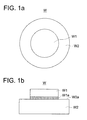
FIG. 1 shows one example of a workpiece used in a first embodiment of the present invention:FIG. 1A is a plan view of a workpiece andFIG. 1B is a side view of the workpiece; -
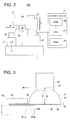
FIG. 2 is a conceptual view showing a schematic constitution of a shape measuring device in the first embodiment of the present invention; -
FIG. 3 is a view showing a shape measuring state of the surface of a workpiece in the first embodiment of the present invention; -
FIG. 4 is a block diagram showing a schematic control constitution used in the first embodiment ofthe present invention; -
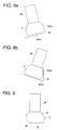
FIG. 5 contains views to illustrate the placement state of a probe and a probe support shaft in the first embodiment of the present invention; -
FIG. 6 is a conceptual view showing a schematic constitution of a shape measuring device in a second embodiment of the present invention; -
FIG. 7 is a block diagram showing a schematic control constitution used in the second embodiment of the present invention; -
FIG. 8 is a view showing a shape measuring state of the surface of a workpiece in the second embodiment of the present invention; -
FIG. 9 shows the shape of a probe as a modified example; -
FIG. 10 shows the shapes of probes as conventional examples; and -
FIG. 11 is a view showing the shape measuring state of the surface of a workpiece in a conventional example. - With reference to the drawings, the preferred embodiments of the present invention will now be described.
- In the present invention, the shape of the outer circumferential face W1a of a workpiece W as shown in
FIG. 1 can be preferably measured. Specifically, a workpiece W is formed by layering 2 cylinders W1 and W2 differing in size. In such a workpiece W, in the outer circumferential face of the cylinder W1 of the top side, an outer circumferential face W1a adjacent to the upper face W2a of the cylinder W2 of the bottom side can be preferably measured. Herein, the upper face W2a of the cylinder W2 is a face intersecting the outer circumferential face W1a of the cylinder W1. - As shown in
FIG. 2 , theshape measuring device 100 is provided with aprobe 3, aprobe support shaft 25 to pivotally support theprobe 3, and aprobe drive device 2, to which theprobe support shaft 25 is attached, to allow theprobe 3 to make contact with the measuring position of the outer circumferential face W1 a of a workpiece W and to move relatively the workpiece W and theprobe 3. - The
probe drive device 2 is provided with abase platform 1, abase 21 fixed on thebase platform 1, aY axis guide 22 fixed to thebase 21 extending in the Y direction, aY stage 23 supported by theY axis guide 22 moving in the Y direction (the Y direction vertical to the X direction), anX stage 24 provided for theY stage 23 to hold aprobe 3 and to allow theprobe 3 to move in the X direction, arotary stage 4 provided on thebase platform 1 to rotatably support a workpiece W, and acontrol device 5 to control the operation of theY stage 23, theX stage 24, and therotary stage 4. - A
probe support shaft 25 extending downward is attached to theX stage 24 and aprobe 3 is attached to the tip of theprobe support shaft 25. - As shown in
FIG. 4 , theX stage 24 has a movingamount displacement detector 241 to detect the moving amount of theX stage 24 in the X direction. The movingamount displacement detector 241 is connected to thecontrol device 5 to output a moving amount having been detected by the movingamount displacement detector 241 to thecontrol device 5. - As shown in
FIG. 3 , theprobe 3 is asphere 31 pivotally supported by theprobe support shaft 25 and has a cur face which is a shape cut so as to be nearly vertical to theprobe support shaft 25 in thesphere 31. - The cut face 32 of the
probe 3 is constituted in such a manner that distance M of the vertical direction between thecut face 32 and the top 33 of thesphere 31 opposed thereto across theequatorial plane 35 of thesphere 31 is at least radius R, and of the surface of thesphere 31, theequatorial position 34 of thesphere 31 is allowed to make contact with the measuring position of the outer circumferential face W1a of a workpiece W. - Further, distance N of the direction nearly vertical to the cut face 32 between the contact position (equatorial position 34) and the
cut face 32 is preferably 10 µm - 60 µm. When distance N is 10 µm - 60 µm, even in the case where, for example, as shown inFIG. 5B , aprobe 5 has some placement shift with respect to theprobe support shaft 25, the placement shift can be absorbed by distance N. Incidentally,FIG. 5A shows an ideal state in placement of theprobe 3 and theprobe support shaft 25. Herein, when distance N is allowed to be less than 10 µm, the above placement shift cannot be absorbed. In the case of more than 60 µm, thecut face 32 is brought into contact with a face (the upper face W2a of the cylinder W2) intersecting a face (the outer circumferential face W1 a) containing the measuring position, whereby interference may occur. - The shape measurement of the outer circumferential face W1a of a workpiece W is carried out while the cut face 32 of a
probe 3 is allowed to face a face (the upper face W2a of the cylinder W2a) intersecting a face containing the measuring position of the outer circumferential face W1 a of a workpiece W and also theequatorial position 34 of thesphere 31 is pressed to and brought into contact with the measuring position of the workpiece W. - The
rotary stage 4 rotates around the rotation axis h passing nearly through the center of a workpiece W (refer toFIG. 2 ), having, as shown inFIG. 4 , anangle displacement detector 41 to detect the angle moving amount oftherotary stage 4. Theangle displacement detector 41 connects to thecontrol device 5 and outputs a moving amount having been detected by theangle displacement detector 41 to thecontrol device 5. - On the
rotary stage 4, a workpiece W to be measured is placed. - As shown in
FIG. 4 , thecontrol device 5 is connected to theX stage 24, theY stage 23, therotary stage 4, the movingamount displacement detector 241, and theangle displacement detector 41. Thecontrol device 5 is provided with a CPU (Central Processing Unit) 51, a RAM (Random Access Memory) 52, and a ROM (Read Only Memory) 53 (refer toFIG. 2 ) to control the operation of theX stage 24, theY stage 23, and therotary stage 4. In thecontrol device 5, a program specified from various kinds of programs stored in theROM 53 is developed on theRAM 52. Then, the thus-developed program cooperates with theCPU 51 to carry out various processings. - Next, a method to measure the shape of the outer circumferential face W1 a of a workpiece W using the
shape measuring device 100 will be described. - Initially, the cut face 32 of a
probe 3 is allowed to face with a face (the upper face W2a of the cylinder W2a) intersecting a face containing the measuring position of the outer circumferential face W1a of a workpiece W, and also in order for theequatorial position 34 of theprobe 3 to make contact with the measuring position of the outer circumferential face W1 a of the workpiece W, theY stage 23 and theX stage 24 are moved. At this moment, theX stage 24 is controlled so that theprobe 3 has constant pressing power to the workpiece W. - Then, the rotary stage is allowed to rotate at least one revolution and at a predetermined interval, the angle displacement amount of the
rotary stage 4 and the movement displacement amount of theX stage 24 are synchronized. Then, the angle displacement amount and the movement displacement amount of theX stage 24 at this moment are detected by theangle displacement detector 41 and the movingamount displacement detector 241, respectively, and the thus-detected values are output to theCPU 51. The detected values having been output to theCPU 51 are stored in theRAM 52 as measurement data. - Since such measurement data is a value offset by a value of radius R of the
sphere 31 of theprobe 3 with respect to the actual outer shape value of the workpiece W, using measurement data stored in theRAM 52, a value of radius R is offset in the normal direction to obtain the actual value of the workpiece W. For details, since in theROM 53, data of the XY coordinate of the center of theprobe 3 in the initial stage is previously stored, using the XY coordinate of the center of theprobe 3 at the initial stage, as well as the movement displacement amount of theX stage 24 and the angle displacement amount of therotary stage 4 at each contact point detected by the movingamount displacement detector 41 and theangle displacement detector 241, the XY coordinate of the center of theprobe 3 in the measuring position is calculated. Then, with respect to this calculated measurement data, a value of radius R in the contact position (equatorial position 34) of theprobe 3 is offSet. Via such measurement, outer circumferential shape data of a desired position of the workpiece W is obtained. - As described above, the
shape measuring device 100 is provided with aprobe 3, aprobe support shaft 25, and a provedrive device 2. Theprobe 3 is asphere 31 pivotally supported by theprobe support shaft 25, having acut face 32 which is a shape cut so as to be nearly vertical to theprobe support shaft 25 in thesphere 31, whereby theprobe 3 is used in such a manner that thecut face 32 is allowed to face a face (the upper face W2a of the cylinder W2) intersecting the outer circumferential face W1a containing the measuring position of a workpiece W and also the surface of thesphere 31 is allowed to make contact with the measuring position of the workpiece W. Namely, thecut face 32 makes it possible to prevent physical interference with the face (the upper face W2a of the cylinder W2) which results in interference in measurement. Thereby, highly precise measurement can be carried out. - Further, as compared in the conventional manner, to prevent physical interference with a face (the upper face W2a of the cylinder W2) which results in interference in measurement, the R of the
sphere 31 needs not to be small and thereby asphere 31 having larger size can be used. Thereby, the accuracy of rolling friction of thesphere 31 is increased and then a true sphere of further high precision can be produced. Still further, since the size of thesphere 31 can be increased, the attachment area with respect to theprobe support shaft 25 can be increased and then the bonding power between theprobe 3 and theprobe support shaft 25 is enhanced, resulting in easy handling. Furthermore, since theprobe support shaft 25 can be thickened, theprobe support shaft 25 can be prevented from bending and then measurement error due to bending is prevented, whereby highly precise measurement can be carried out - Further, the cut face 32 of the
probe 3 is constituted in such a manner that distance M of the vertical direction between thecut face 32 and the top 33 of thesphere 31 opposed thereto across theequatorial plane 35 of thesphere 31 is at least radius R of thesphere 31, and of the surface ofsphere 31, theequatorial position 34 of thesphere 31 is allowed to make contact with the measuring position of the outer circumferential face W1a of workpiece W, leading to further highly precise measurement - Still further, the
probe drive device 2 is provided with anX stage 24, aY stage 23, arotary stage 4 to rotate a workpiece W, and acontrol device 5 to control the operation thereof. Therefore, as theprobe 3 is moved in the XY directions, the workpiece W is rotated and thereby theprobe 3 can be accurately and assuredly brought into contact with the measuring position of the outer circumferential face W I of the workpiece W. Thereby also in this respect, highly precise measurement can be carried out. - In a second embodiment, a device differing from the
shape measuring device 100 of the first embodiment is employed in which aprobe 3 can be moved in the Z direction with respect to a workpiece W and the inclination of aprobe support shaft 25 can be adjusted. - As shown in
FIG. 6 , theshape measuring device 600 is provided with aprobe 3, aprobe support shaft 25 to pivotally support theprobe 3, and a probe drive device 7, to which theprobe support shaft 25 is attached, to allow theprobe 3 to make contact with the measuring position of the outer circumferential face W3a (refer toFIG. 8 ) of a workpiece W and to move relatively the workpiece W and theprobe 3. - The probe drive device 7 is provided with a
base platform 6, aZ stage 71 provided on thebase platform 6 moving in the Z direction (the Z direction vertical to the X direction and the Y direction), anX stage 72 provided on theZ stage 71 moving in the X direction, aY axis guide 73 fixed on theX stage 72 extending in the Y direction, and aY stage 74 supported by theY axis guide 73 moving in the Y direction (the Y direction vertical to the X direction). - Further, the probe drive device 7 is provided with a
rotary stage 76 attached to theY stage 74 via anattachment member 75, a tiltingstage 77 attached to the bottom face of therotary stage 76, and acontrol device 9 to control the operation of theX stage 72, theY stage 74, theZ stage 71, therotary stage 76, and the tiltingstage 77. - The
rotary stage 76 rotates around the vertical axis k. The tiltingstage 77 moves in an arc manner around the rotational center i arranged on theprobe support shaft 25 to adjust the inclination of theprobe 3. To the bottom face of the tiltingstage 77, acontact displacement sensor 78 is attached. - The
contact displacement sensor 78 detects a contact position when theprobe 3 has made contact with the measuring position of a workpiece W and then outputs the contact position to thecontrol device 9. To the bottom face of thecontact displacement sensor 78, aprobe support shaft 25 extending downward is attached, and further to the lower end of theprobe support shaft 25, theprobe 3 is attached. - As shown in
FIG. 7 , theX stage 72, theY stage 74, and theZ stage 71 each have a movingamount displacement detectors 721, 741,711 to detect each moving amount. These moving amount displacement detectors 721,741,711 are connected to thecontrol device 9, and moving displacement amounts having been detected by the moving amount displacement detectors 721,741,711 are output to thecontrol device 9. - The
rotary stage 76 and the tiltingstage 77 each haveangle displacement detectors rotary stage 76 and the tiltingstage 77. Theangle displacement detectors control device 9 to output angle displacement amounts having been detected by theangle displacement detectors - As a
probe 3, the same one as theprobe 3 in the first embodiment is usable, which is asphere 31 pivotally supported by theprobe support shaft 25, having acut face 32 which is a shape cut so as to be nearly vertical to theprobe support shaft 25 in thesphere 31. Further, a workpiece W to be measured includes those in which, for example, as shown inFIG. 8 , a face W3b intersecting the outer circumferential face W3a containing a measuring position is inclined against the outer circumferential face W3a. - On the
support platform 8, a workpiece W to be measured is placed. - As shown in
FIG. 7 , thecontrol device 9 is connected to anX stage 72, aY stage 74, aZ stage 71, arotary stage 76, a tiltingstage 77, moving amount displacement detectors 721,741, and 711,angle displacement detectors contact displacement sensor 78. Thecontrol device 9 is provided with a CPU (Central Processing Unit) 91, a RAM (Random Access Memory) 92, and a ROM (Read Only Memory) 93 (refer toFIG. 6 ) to control the operation of theX stage 72, theY stage 74, theZ stage 71, therotary stage 76, and the tiltingstage 77. In thecontrol device 9, a program specified from various kinds of programs stored in theROM 93 is developed on theRAM 92. Then, the thus-developed program cooperates with theCPU 91 to carry out various processings. - Next, a method to measure the shape of the outer circumferential face W3a of a workpiece W using the
shape measuring device 600 will be described. - Initially, using numerical data of the shape of a workpiece W previously input in the
ROM 93, the cut face 32 of aprobe 3 is allowed to face a face W3b intersecting a face containing the measuring position of the outer circumferential face W3a of a workpiece W, and also in order for theequatorial position 34 of theprobe 3 to make contact with the measuring position of the outer circumferential face W3a of the workpiece W, theX stage 72, theY stage 74, theZ stage 71, therotary stage 76, and the tiltingstage 77 are moved. At this moment, for example, as shown inFIGS. 8A and 8B , theprobe 3 is brought into contact so that the face W3b intersecting the outer circumferential face W3a containing the measuring position is avoided by the cut face 32 of theprobe 3. - Contact position is detected by the
contact displacement sensor 78, and at the position, theprobe support shaft 25 is stopped. The angle displacement amounts oftherotary stage 76 and the tiltingstage 77 at this moment each are detected by theangle displacement detectors X stage 72, theY stage 74, and theZ stage 71 are detected by the moving amount displacement detectors 721,741, and 711 to output the thus-detected values to theCPU 91. - The detected values having been output to the
CPU 91 are stored in theRAM 92 as measurement data. This operation is repeated to obtain measurement data of a desired position of the workpiece W. - Since such measurement data is a value offset by a value of radius R of the
sphere 31 of theprobe 3 with respect to the actual outer shape value of the workpiece W, using measurement data stored in theRAM 52, a value of radius R is offset in the normal direction to obtain the actual value of the workpiece W. - As described above, also in the second embodiment, in the same manner as in the first embodiment, a
probe 3, aprobe support shaft 25, and a probe drive device 7 are provided. Theprobe 3 is asphere 31 pivotally supported by theprobe support shaft 25 and has acut face 32 which is a shape cut so as to be nearly vertical to theprobe support shaft 25 in thesphere 31. Thereby, the same effects as in the first embodiment can be produced. - Further, especially, the prove drive device 7 in the second embodiment is provided with an
X stage 72, aY stage 74, aZ stage 71, arotary stage 76, a tiltingstage 77, and acontrol device 9. Thereby, when aprobe 3 is moved in the XYZ directions and then rotation or inclination is adjusted, even a workpiece W having a complex shape and a face resulting in interference in measurement can be easily allowed to correspond to the measuring position. As a result, theprobe 3 is assuredly brought into contact and thereby further highly precise measurement can be carried out. - The present invention is not limited to the above embodiments and can be appropriately modified without departing from the gist of the present invention.
- For example, as shown in
FIG. 9 , theprobe 3 may be provided with a cut face forinterference 36 formed by cutting a part except the cut face 32 of the surface ofsphere 31. When such a cut face forinterference 36 is provided, in addition to the faces W2a and W3a resulting in interference in measurement, another face resulting in interference can be avoided. Thereby, smooth and highly precise measurement can be carried out Further, such a cut face forinterference 36 may be plurally provided depending to the shape of a workpiece W. - Further, as the workpieces W used in the above embodiments, those shown in
FIG. 1 andFIG. 8 have been cited with no limitation thereto. A workpiece W having a curved surface is employable and modifications can be appropriately made. -
- 2:
- probe drive device
- 3:
- probe
- 5, 9:
- control device
- 23, 74:
- Y stage (Y axis moving mechanism)
- 24, 72:
- X stage (X axis moving mechanism)
- 25:
- probe support shaft
- 31:
- sphere
- 32:
- cut face
- 33:
- top
- 34:
- equatorial position
- 35:
- equatorial plane
- 36:
- cut face for interference
- 76:
- rotary stage (rotary mechanism)
- 77:
- tilting stage (tilting mechanism)
- 71:
- Z stage (Z axis moving mechanism)
- 100, 600:
- shape measuring device
- W:
- workpiece
- M, N:
- distance
Claims (6)
- A shape measuring device to measure a surface shape of a workpiece based on a moving amount of a probe by contacting or moving while in contact the probe with a surface of the workpiece, wherein the shape measuring device comprises:the probe;a probe support shaft to pivotally support the probe; anda probe drive device to which the probe support shaft is attached to contact the probe with a measuring position of the surface of the workpiece and to move relatively the workpiece and the probe;wherein the probe is a sphere pivotally supported by the probe support shaft and has a cut face which is a shape cut so as to be nearly vertical to the probe support shaft in the sphere; anda shape measurement of the surface of the workpiece is carried out in such a manner that the cut face of the probe is faced with a face intersecting a face containing the measuring position of the surface of the workpiece, and a surface of the sphere is contacted with the measuring position ofthe workpiece.
- The shape measuring device of claim 1,
wherein a distance of the vertical direction between the cut face and the top of the sphere opposed thereto across a plane of an equator ofthe sphere is at least radius R of the sphere; and
a position of the equator of the surface of the sphere is made contact with the measuring position of the workpiece. - The shape measuring device of claim 2,
wherein a distance of the direction nearly vertical to the cut face between a position which contacted a position of the equator of the sphere for the measuring position of the workpiece and the cut face is 0 µm - 60 µm. - The shape measuring device of the Claims 1 to 3,
wherein the probe further comprises at least one of a cut face for interference formed by cutting a part of the sphere except the cut face of the sphere. - The shape measuring device in any one of the Claims 1 to 4,
wherein the probe drive device further comprises:a X-axis move section to move the probe in a direction of X to the workpiece;a Y-axis move section to move the probe in a direction ofY which is vertical to the direction of X to the workpiece;a rotary section supporting the workpiece and rotating the workpiece centering on a rotation axis passing through nearly center of the workpiece;a control device to controll start and stop of the X-axis move section, the Y-axis move section, and the rotary section so as to contacts the probe to a predetermined position of the workpiece. - The shape measuring device in any one of the Claims 1 to 4,
wherein the probe drive device further comprises:a X-axis move section to move the probe in a direction of X to the workpiece;a Y-axis move section to move the probe in a direction ofY which is vertical to the direction of X to the workpiece;a Z-axis move section move the probe in a direction ofZ which is vertical to the direction of X and the direction of Y to the workpiece;a rotary section to rotate the probe centering on the probe support shaft;a tilting section adjusting an inclination of the probea control device control start and stop of the X-axis move section, the Y-axis move section, Z-axis move section, the rotary section and the tilting section so as to contact the probe to a measureing position of the workpiece.
Applications Claiming Priority (2)
| Application Number | Priority Date | Filing Date | Title |
|---|---|---|---|
| JP2009071420 | 2009-03-24 | ||
| PCT/JP2010/052162 WO2010109975A1 (en) | 2009-03-24 | 2010-02-15 | Shape measuring device |
Publications (3)
| Publication Number | Publication Date |
|---|---|
| EP2413090A1 true EP2413090A1 (en) | 2012-02-01 |
| EP2413090A4 EP2413090A4 (en) | 2015-04-15 |
| EP2413090B1 EP2413090B1 (en) | 2018-06-06 |
Family
ID=42780671
Family Applications (1)
| Application Number | Title | Priority Date | Filing Date |
|---|---|---|---|
| EP10755776.1A Not-in-force EP2413090B1 (en) | 2009-03-24 | 2010-02-15 | Shape measuring device |
Country Status (7)
| Country | Link |
|---|---|
| US (1) | US8561309B2 (en) |
| EP (1) | EP2413090B1 (en) |
| JP (1) | JP4748287B2 (en) |
| KR (1) | KR20120006979A (en) |
| CN (1) | CN102362143B (en) |
| TW (1) | TWI473967B (en) |
| WO (1) | WO2010109975A1 (en) |
Families Citing this family (9)
| Publication number | Priority date | Publication date | Assignee | Title |
|---|---|---|---|---|
| CN103455045A (en) * | 2012-05-30 | 2013-12-18 | 鸿富锦精密工业(深圳)有限公司 | Touch movement control system and touch movement control method |
| JP6169339B2 (en) * | 2012-10-04 | 2017-07-26 | 株式会社日立製作所 | Shape measuring method and apparatus |
| GB201311600D0 (en) * | 2013-06-28 | 2013-08-14 | Renishaw Plc | Calibration of a contact probe |
| CN104316547B (en) * | 2014-11-05 | 2017-04-19 | 同方威视技术股份有限公司 | Rotary arc detector box for X-ray testing device |
| KR101915948B1 (en) * | 2016-10-31 | 2019-01-30 | 창원대학교 산학협력단 | A compound profile meter |
| US10969760B2 (en) | 2018-04-12 | 2021-04-06 | Faro Technologies, Inc. | Coordinate measurement system with auxiliary axis |
| US11874101B2 (en) | 2018-04-12 | 2024-01-16 | Faro Technologies, Inc | Modular servo cartridges for precision metrology |
| JP7471485B1 (en) * | 2023-03-01 | 2024-04-19 | 株式会社牧野フライス製作所 | Touch probe |
| CN119826751A (en) * | 2024-12-31 | 2025-04-15 | 东莞市鑫焱精密刀具有限公司 | Probe and detection device |
Family Cites Families (22)
| Publication number | Priority date | Publication date | Assignee | Title |
|---|---|---|---|---|
| JPS507458A (en) * | 1973-05-18 | 1975-01-25 | ||
| JPS507458U (en) * | 1973-05-21 | 1975-01-25 | ||
| DE3678961D1 (en) * | 1986-12-09 | 1991-05-29 | Erowa Ag | MEASURING DEVICE FOR DETERMINING THE DIMENSIONS OF AN OBJECT IN THREE DIMENSIONS. |
| GB8629437D0 (en) * | 1986-12-09 | 1987-01-21 | Reinshaw Plc | Displacement-sensing probe |
| GB8815984D0 (en) * | 1988-07-05 | 1988-08-10 | Univ Brunel | Probes |
| GB8906287D0 (en) * | 1989-03-18 | 1989-05-04 | Renishaw Plc | Probe calibration |
| JPH06288704A (en) * | 1993-04-06 | 1994-10-18 | Toshiba Ceramics Co Ltd | Inner diameter measuring device |
| JPH09133512A (en) * | 1995-11-07 | 1997-05-20 | Sanyo Mach Works Ltd | Optical three-dimensional measurement method |
| JP3602310B2 (en) * | 1997-10-21 | 2004-12-15 | 松下電器産業株式会社 | Flatness measurement device |
| JP2000304529A (en) * | 1999-04-22 | 2000-11-02 | Ricoh Co Ltd | Probe device and shape measuring device |
| JP3516630B2 (en) | 2000-03-29 | 2004-04-05 | 株式会社ミツトヨ | Shape measuring machine and shape measuring method |
| JP3784273B2 (en) * | 2000-05-01 | 2006-06-07 | 株式会社ミツトヨ | Work shape measuring sensor and work shape measuring device |
| JP4794753B2 (en) | 2001-06-04 | 2011-10-19 | パナソニック株式会社 | Shape measurement method |
| GB0126232D0 (en) * | 2001-11-01 | 2002-01-02 | Renishaw Plc | Calibration of an analogue probe |
| JP2005147673A (en) * | 2003-11-11 | 2005-06-09 | Nissan Motor Co Ltd | Three-dimensional coordinate measuring probe and three-dimensional coordinate measuring apparatus using the probe |
| JP2006125934A (en) | 2004-10-27 | 2006-05-18 | Matsushita Electric Ind Co Ltd | Measuring probe and measuring method |
| GB0608235D0 (en) * | 2006-04-26 | 2006-06-07 | Renishaw Plc | Differential calibration |
| JP5221004B2 (en) * | 2006-05-25 | 2013-06-26 | 株式会社ミツトヨ | Measuring device, surface texture measuring method, and surface texture measuring program |
| DE102007051054A1 (en) * | 2007-10-19 | 2009-04-30 | Carl Zeiss Industrielle Messtechnik Gmbh | Method for correcting the measured values of a coordinate measuring machine and coordinate measuring machine |
| DE102009049534A1 (en) * | 2009-10-06 | 2011-04-07 | Carl Zeiss Industrielle Messtechnik Gmbh | Coordinate measuring machine with position change sensors |
| EP2385339A1 (en) * | 2010-05-05 | 2011-11-09 | Leica Geosystems AG | Surface sensing device with optical monitoring system |
| JP5612386B2 (en) * | 2010-07-23 | 2014-10-22 | 株式会社ミツトヨ | Shape measuring device |
-
2010
- 2010-02-15 JP JP2011505927A patent/JP4748287B2/en active Active
- 2010-02-15 KR KR1020117021920A patent/KR20120006979A/en not_active Withdrawn
- 2010-02-15 CN CN2010800129756A patent/CN102362143B/en not_active Expired - Fee Related
- 2010-02-15 US US13/258,255 patent/US8561309B2/en active Active
- 2010-02-15 WO PCT/JP2010/052162 patent/WO2010109975A1/en not_active Ceased
- 2010-02-15 EP EP10755776.1A patent/EP2413090B1/en not_active Not-in-force
- 2010-03-18 TW TW99108006A patent/TWI473967B/en not_active IP Right Cessation
Also Published As
| Publication number | Publication date |
|---|---|
| US8561309B2 (en) | 2013-10-22 |
| EP2413090B1 (en) | 2018-06-06 |
| CN102362143B (en) | 2013-11-13 |
| TWI473967B (en) | 2015-02-21 |
| US20120017455A1 (en) | 2012-01-26 |
| CN102362143A (en) | 2012-02-22 |
| TW201105927A (en) | 2011-02-16 |
| KR20120006979A (en) | 2012-01-19 |
| WO2010109975A1 (en) | 2010-09-30 |
| EP2413090A4 (en) | 2015-04-15 |
| JP4748287B2 (en) | 2011-08-17 |
| JPWO2010109975A1 (en) | 2012-09-27 |
Similar Documents
| Publication | Publication Date | Title |
|---|---|---|
| EP2413090A1 (en) | Shape measuring device | |
| US6327788B1 (en) | Surface form measurement | |
| US9151602B2 (en) | Corrected ball diameter calculating method and form measuring instrument | |
| CN103759941B (en) | A kind of Measuring of Axis Rotating Accuracy detection method | |
| US6460261B1 (en) | V-groove shape measuring method and apparatus by using rotary table | |
| JP4459264B2 (en) | Three-dimensional shape measurement method | |
| US11592278B2 (en) | Method and apparatus for determining a relative position of an axis of rotation of a rotary table for a coordinate measuring machine | |
| JP2012159499A (en) | Measuring apparatus and measuring method for ball screw | |
| JP3433710B2 (en) | V-groove shape measuring method and apparatus | |
| JP2751483B2 (en) | Groove or ridge accuracy measurement method and accuracy measurement device and accuracy evaluation method | |
| JP2002005653A (en) | Method and apparatus for measurement of screw dimension | |
| JP2001264048A (en) | Method and device for measuring shape of v-groove | |
| JP7681822B2 (en) | Calibration unit and calibration method | |
| JP3748866B2 (en) | Tool measuring apparatus and method | |
| JP5218957B2 (en) | Shape measuring device, shape measuring method, and shape measuring program | |
| JP4704932B2 (en) | Stylus type shape measuring device and method and rotation restricting air cylinder suitable for the same | |
| JP7553052B2 (en) | Cutting circumferential surface measuring device and cutting workpiece measuring method | |
| CN116164693A (en) | Gear profile measuring system and method | |
| JP2004012430A (en) | Non-contact measurement method and measurement device | |
| JP5332010B2 (en) | Shape measuring apparatus, shape measuring method, and shape measuring program | |
| JP3937669B2 (en) | Spherical measurement method | |
| JPH10286745A (en) | Work measurement method for nc machine tool | |
| JP2004012431A (en) | Non-contact measurement method and measurement device | |
| JPH08141886A (en) | Drill runout measuring device | |
| JPH03118412A (en) | Measuring method by shape measuring apparatus |
Legal Events
| Date | Code | Title | Description |
|---|---|---|---|
| PUAI | Public reference made under article 153(3) epc to a published international application that has entered the european phase |
Free format text: ORIGINAL CODE: 0009012 |
|
| 17P | Request for examination filed |
Effective date: 20110921 |
|
| AK | Designated contracting states |
Kind code of ref document: A1 Designated state(s): AT BE BG CH CY CZ DE DK EE ES FI FR GB GR HR HU IE IS IT LI LT LU LV MC MK MT NL NO PL PT RO SE SI SK SM TR |
|
| DAX | Request for extension of the european patent (deleted) | ||
| RA4 | Supplementary search report drawn up and despatched (corrected) |
Effective date: 20150312 |
|
| RIC1 | Information provided on ipc code assigned before grant |
Ipc: G01B 5/016 20060101ALI20150306BHEP Ipc: G01B 5/20 20060101AFI20150306BHEP Ipc: G01B 5/012 20060101ALI20150306BHEP |
|
| GRAP | Despatch of communication of intention to grant a patent |
Free format text: ORIGINAL CODE: EPIDOSNIGR1 |
|
| STAA | Information on the status of an ep patent application or granted ep patent |
Free format text: STATUS: GRANT OF PATENT IS INTENDED |
|
| INTG | Intention to grant announced |
Effective date: 20180119 |
|
| GRAS | Grant fee paid |
Free format text: ORIGINAL CODE: EPIDOSNIGR3 |
|
| GRAA | (expected) grant |
Free format text: ORIGINAL CODE: 0009210 |
|
| STAA | Information on the status of an ep patent application or granted ep patent |
Free format text: STATUS: THE PATENT HAS BEEN GRANTED |
|
| AK | Designated contracting states |
Kind code of ref document: B1 Designated state(s): AT BE BG CH CY CZ DE DK EE ES FI FR GB GR HR HU IE IS IT LI LT LU LV MC MK MT NL NO PL PT RO SE SI SK SM TR |
|
| REG | Reference to a national code |
Ref country code: GB Ref legal event code: FG4D |
|
| REG | Reference to a national code |
Ref country code: CH Ref legal event code: EP Ref country code: AT Ref legal event code: REF Ref document number: 1006592 Country of ref document: AT Kind code of ref document: T Effective date: 20180615 |
|
| REG | Reference to a national code |
Ref country code: IE Ref legal event code: FG4D |
|
| REG | Reference to a national code |
Ref country code: DE Ref legal event code: R096 Ref document number: 602010051121 Country of ref document: DE |
|
| REG | Reference to a national code |
Ref country code: NL Ref legal event code: MP Effective date: 20180606 |
|
| REG | Reference to a national code |
Ref country code: LT Ref legal event code: MG4D |
|
| PG25 | Lapsed in a contracting state [announced via postgrant information from national office to epo] |
Ref country code: CY Free format text: LAPSE BECAUSE OF FAILURE TO SUBMIT A TRANSLATION OF THE DESCRIPTION OR TO PAY THE FEE WITHIN THE PRESCRIBED TIME-LIMIT Effective date: 20180606 Ref country code: LT Free format text: LAPSE BECAUSE OF FAILURE TO SUBMIT A TRANSLATION OF THE DESCRIPTION OR TO PAY THE FEE WITHIN THE PRESCRIBED TIME-LIMIT Effective date: 20180606 Ref country code: SE Free format text: LAPSE BECAUSE OF FAILURE TO SUBMIT A TRANSLATION OF THE DESCRIPTION OR TO PAY THE FEE WITHIN THE PRESCRIBED TIME-LIMIT Effective date: 20180606 Ref country code: NO Free format text: LAPSE BECAUSE OF FAILURE TO SUBMIT A TRANSLATION OF THE DESCRIPTION OR TO PAY THE FEE WITHIN THE PRESCRIBED TIME-LIMIT Effective date: 20180906 Ref country code: BG Free format text: LAPSE BECAUSE OF FAILURE TO SUBMIT A TRANSLATION OF THE DESCRIPTION OR TO PAY THE FEE WITHIN THE PRESCRIBED TIME-LIMIT Effective date: 20180906 Ref country code: FI Free format text: LAPSE BECAUSE OF FAILURE TO SUBMIT A TRANSLATION OF THE DESCRIPTION OR TO PAY THE FEE WITHIN THE PRESCRIBED TIME-LIMIT Effective date: 20180606 Ref country code: ES Free format text: LAPSE BECAUSE OF FAILURE TO SUBMIT A TRANSLATION OF THE DESCRIPTION OR TO PAY THE FEE WITHIN THE PRESCRIBED TIME-LIMIT Effective date: 20180606 |
|
| PG25 | Lapsed in a contracting state [announced via postgrant information from national office to epo] |
Ref country code: HR Free format text: LAPSE BECAUSE OF FAILURE TO SUBMIT A TRANSLATION OF THE DESCRIPTION OR TO PAY THE FEE WITHIN THE PRESCRIBED TIME-LIMIT Effective date: 20180606 Ref country code: GR Free format text: LAPSE BECAUSE OF FAILURE TO SUBMIT A TRANSLATION OF THE DESCRIPTION OR TO PAY THE FEE WITHIN THE PRESCRIBED TIME-LIMIT Effective date: 20180907 Ref country code: LV Free format text: LAPSE BECAUSE OF FAILURE TO SUBMIT A TRANSLATION OF THE DESCRIPTION OR TO PAY THE FEE WITHIN THE PRESCRIBED TIME-LIMIT Effective date: 20180606 |
|
| REG | Reference to a national code |
Ref country code: AT Ref legal event code: MK05 Ref document number: 1006592 Country of ref document: AT Kind code of ref document: T Effective date: 20180606 |
|
| PG25 | Lapsed in a contracting state [announced via postgrant information from national office to epo] |
Ref country code: NL Free format text: LAPSE BECAUSE OF FAILURE TO SUBMIT A TRANSLATION OF THE DESCRIPTION OR TO PAY THE FEE WITHIN THE PRESCRIBED TIME-LIMIT Effective date: 20180606 |
|
| PG25 | Lapsed in a contracting state [announced via postgrant information from national office to epo] |
Ref country code: AT Free format text: LAPSE BECAUSE OF FAILURE TO SUBMIT A TRANSLATION OF THE DESCRIPTION OR TO PAY THE FEE WITHIN THE PRESCRIBED TIME-LIMIT Effective date: 20180606 Ref country code: IS Free format text: LAPSE BECAUSE OF FAILURE TO SUBMIT A TRANSLATION OF THE DESCRIPTION OR TO PAY THE FEE WITHIN THE PRESCRIBED TIME-LIMIT Effective date: 20181006 Ref country code: EE Free format text: LAPSE BECAUSE OF FAILURE TO SUBMIT A TRANSLATION OF THE DESCRIPTION OR TO PAY THE FEE WITHIN THE PRESCRIBED TIME-LIMIT Effective date: 20180606 Ref country code: CZ Free format text: LAPSE BECAUSE OF FAILURE TO SUBMIT A TRANSLATION OF THE DESCRIPTION OR TO PAY THE FEE WITHIN THE PRESCRIBED TIME-LIMIT Effective date: 20180606 Ref country code: RO Free format text: LAPSE BECAUSE OF FAILURE TO SUBMIT A TRANSLATION OF THE DESCRIPTION OR TO PAY THE FEE WITHIN THE PRESCRIBED TIME-LIMIT Effective date: 20180606 Ref country code: SK Free format text: LAPSE BECAUSE OF FAILURE TO SUBMIT A TRANSLATION OF THE DESCRIPTION OR TO PAY THE FEE WITHIN THE PRESCRIBED TIME-LIMIT Effective date: 20180606 Ref country code: PL Free format text: LAPSE BECAUSE OF FAILURE TO SUBMIT A TRANSLATION OF THE DESCRIPTION OR TO PAY THE FEE WITHIN THE PRESCRIBED TIME-LIMIT Effective date: 20180606 |
|
| PG25 | Lapsed in a contracting state [announced via postgrant information from national office to epo] |
Ref country code: IT Free format text: LAPSE BECAUSE OF FAILURE TO SUBMIT A TRANSLATION OF THE DESCRIPTION OR TO PAY THE FEE WITHIN THE PRESCRIBED TIME-LIMIT Effective date: 20180606 Ref country code: SM Free format text: LAPSE BECAUSE OF FAILURE TO SUBMIT A TRANSLATION OF THE DESCRIPTION OR TO PAY THE FEE WITHIN THE PRESCRIBED TIME-LIMIT Effective date: 20180606 |
|
| REG | Reference to a national code |
Ref country code: DE Ref legal event code: R097 Ref document number: 602010051121 Country of ref document: DE |
|
| PLBE | No opposition filed within time limit |
Free format text: ORIGINAL CODE: 0009261 |
|
| STAA | Information on the status of an ep patent application or granted ep patent |
Free format text: STATUS: NO OPPOSITION FILED WITHIN TIME LIMIT |
|
| 26N | No opposition filed |
Effective date: 20190307 |
|
| PG25 | Lapsed in a contracting state [announced via postgrant information from national office to epo] |
Ref country code: SI Free format text: LAPSE BECAUSE OF FAILURE TO SUBMIT A TRANSLATION OF THE DESCRIPTION OR TO PAY THE FEE WITHIN THE PRESCRIBED TIME-LIMIT Effective date: 20180606 Ref country code: DK Free format text: LAPSE BECAUSE OF FAILURE TO SUBMIT A TRANSLATION OF THE DESCRIPTION OR TO PAY THE FEE WITHIN THE PRESCRIBED TIME-LIMIT Effective date: 20180606 |
|
| REG | Reference to a national code |
Ref country code: CH Ref legal event code: PL |
|
| PG25 | Lapsed in a contracting state [announced via postgrant information from national office to epo] |
Ref country code: LU Free format text: LAPSE BECAUSE OF NON-PAYMENT OF DUE FEES Effective date: 20190215 Ref country code: MC Free format text: LAPSE BECAUSE OF FAILURE TO SUBMIT A TRANSLATION OF THE DESCRIPTION OR TO PAY THE FEE WITHIN THE PRESCRIBED TIME-LIMIT Effective date: 20180606 |
|
| REG | Reference to a national code |
Ref country code: BE Ref legal event code: MM Effective date: 20190228 |
|
| REG | Reference to a national code |
Ref country code: IE Ref legal event code: MM4A |
|
| PG25 | Lapsed in a contracting state [announced via postgrant information from national office to epo] |
Ref country code: LI Free format text: LAPSE BECAUSE OF NON-PAYMENT OF DUE FEES Effective date: 20190228 Ref country code: CH Free format text: LAPSE BECAUSE OF NON-PAYMENT OF DUE FEES Effective date: 20190228 |
|
| PG25 | Lapsed in a contracting state [announced via postgrant information from national office to epo] |
Ref country code: IE Free format text: LAPSE BECAUSE OF NON-PAYMENT OF DUE FEES Effective date: 20190215 |
|
| PG25 | Lapsed in a contracting state [announced via postgrant information from national office to epo] |
Ref country code: BE Free format text: LAPSE BECAUSE OF NON-PAYMENT OF DUE FEES Effective date: 20190228 Ref country code: FR Free format text: LAPSE BECAUSE OF NON-PAYMENT OF DUE FEES Effective date: 20190228 |
|
| PG25 | Lapsed in a contracting state [announced via postgrant information from national office to epo] |
Ref country code: TR Free format text: LAPSE BECAUSE OF FAILURE TO SUBMIT A TRANSLATION OF THE DESCRIPTION OR TO PAY THE FEE WITHIN THE PRESCRIBED TIME-LIMIT Effective date: 20180606 |
|
| PG25 | Lapsed in a contracting state [announced via postgrant information from national office to epo] |
Ref country code: MT Free format text: LAPSE BECAUSE OF NON-PAYMENT OF DUE FEES Effective date: 20190215 Ref country code: PT Free format text: LAPSE BECAUSE OF FAILURE TO SUBMIT A TRANSLATION OF THE DESCRIPTION OR TO PAY THE FEE WITHIN THE PRESCRIBED TIME-LIMIT Effective date: 20181008 |
|
| PGFP | Annual fee paid to national office [announced via postgrant information from national office to epo] |
Ref country code: DE Payment date: 20210202 Year of fee payment: 12 Ref country code: GB Payment date: 20210203 Year of fee payment: 12 |
|
| PG25 | Lapsed in a contracting state [announced via postgrant information from national office to epo] |
Ref country code: HU Free format text: LAPSE BECAUSE OF FAILURE TO SUBMIT A TRANSLATION OF THE DESCRIPTION OR TO PAY THE FEE WITHIN THE PRESCRIBED TIME-LIMIT; INVALID AB INITIO Effective date: 20100215 |
|
| PG25 | Lapsed in a contracting state [announced via postgrant information from national office to epo] |
Ref country code: MK Free format text: LAPSE BECAUSE OF FAILURE TO SUBMIT A TRANSLATION OF THE DESCRIPTION OR TO PAY THE FEE WITHIN THE PRESCRIBED TIME-LIMIT Effective date: 20180606 |
|
| REG | Reference to a national code |
Ref country code: DE Ref legal event code: R119 Ref document number: 602010051121 Country of ref document: DE |
|
| GBPC | Gb: european patent ceased through non-payment of renewal fee |
Effective date: 20220215 |
|
| PG25 | Lapsed in a contracting state [announced via postgrant information from national office to epo] |
Ref country code: GB Free format text: LAPSE BECAUSE OF NON-PAYMENT OF DUE FEES Effective date: 20220215 Ref country code: DE Free format text: LAPSE BECAUSE OF NON-PAYMENT OF DUE FEES Effective date: 20220901 |