EP2413077A1 - Control method for an air-cooled condenser of an electric power generation plant with automatic selection of state and electric power generation plant - Google Patents
Control method for an air-cooled condenser of an electric power generation plant with automatic selection of state and electric power generation plant Download PDFInfo
- Publication number
- EP2413077A1 EP2413077A1 EP11175886A EP11175886A EP2413077A1 EP 2413077 A1 EP2413077 A1 EP 2413077A1 EP 11175886 A EP11175886 A EP 11175886A EP 11175886 A EP11175886 A EP 11175886A EP 2413077 A1 EP2413077 A1 EP 2413077A1
- Authority
- EP
- European Patent Office
- Prior art keywords
- control quantity
- condition
- condenser
- state
- reference value
- Prior art date
- Legal status (The legal status is an assumption and is not a legal conclusion. Google has not performed a legal analysis and makes no representation as to the accuracy of the status listed.)
- Granted
Links
Images




Classifications
-
- F—MECHANICAL ENGINEERING; LIGHTING; HEATING; WEAPONS; BLASTING
- F28—HEAT EXCHANGE IN GENERAL
- F28B—STEAM OR VAPOUR CONDENSERS
- F28B1/00—Condensers in which the steam or vapour is separate from the cooling medium by walls, e.g. surface condenser
-
- F—MECHANICAL ENGINEERING; LIGHTING; HEATING; WEAPONS; BLASTING
- F28—HEAT EXCHANGE IN GENERAL
- F28B—STEAM OR VAPOUR CONDENSERS
- F28B1/00—Condensers in which the steam or vapour is separate from the cooling medium by walls, e.g. surface condenser
- F28B1/06—Condensers in which the steam or vapour is separate from the cooling medium by walls, e.g. surface condenser using air or other gas as the cooling medium
Definitions
- the present invention relates to a control method for an air-cooled condenser of an electric power generation plant with automatic selection of state and to an electric power generation plant.
- a combined cycle plant comprises at least one gas turbine and a steam turbine, one or more electric generators, a recovery boiler and a condenser.
- the recovery boiler receives hot exhaust gases from the gas turbine and utilizes them for producing steam in appropriate conditions to be supplied to different sections (high, medium and low pressure) of the steam turbine.
- the condenser is generally of the air type (ACC, Air-Cooled Condenser) and condenses the steam deriving from the steam turbine or from by-pass systems with which steam turbines are normally provided, transferring the residual heat into the atmosphere.
- ACC Air-Cooled Condenser
- An air-cooled condenser typically comprises a plurality of tube bundle lines, in which the steam flows, and a plurality of fans, organized as a matrix in rows and columns and arranged so as to cool the steam flowing through the tube bundles.
- the major fraction (about 90%) of the steam is condensed into tube bundles thus condensed by means of fans belonging to primary modules and therefore collected, by gravity, into a collection tank.
- the condensate will then be taken from the collection tank by means of extraction pumps and sent to the recovery boiler.
- the remaining fraction (about 10%) of the steam is condensed in tube bundles cooled by fans belonging to sub modules and the residual air (non-condensable gases) is conveyed to an air extraction system, to be evacuated into the atmosphere.
- the cooling action required of the condenser naturally varies depending both on the power supplied by the plant (load), and the environmental conditions (pressure and temperature).
- the intensity of the cooling depends on the number of fans and by their speed, which must be properly controlled.
- the fans in particular, can be switched off or operated at constant speed, selected in a set of values.
- the monitoring operations are critical, however, due to the high power absorbed by each fan (often several tens of kilowatts). Turning on a fan, for example, involves the absorption of a high current peak, as well as, although to a lesser extent, the increase in speed. It is possible therefore that overloads may occur for the medium/low voltage transformers that power the motors of the fans. Even when the fan speed is reduced, it is necessary to ensure proper motor demagnetization. The speed variations lead to greater wear on mechanical parts.
- the aim of the present invention is therefore to provide a control method for an air-cooled condenser of an electric power generation plant and an electric power generation plant that allows to avoid unnecessary state transitions, without compromising the performance of the condenser.
- Implemented according to the present invention are a method for controlling an air-cooled condenser of an electric power generation plant and an electric power generation plant as defined respectively in claims 1 and 12.
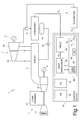
- a combined cycle plant for generating electric power comprises a gas turbine group 2, a steam turbine 3, two alternators, 4, 5, respectively, coupled to the gas turbine 2 and the steam turbine 3, a recovery boiler 7, which operates as a steam generator, a condenser 8, an acquisition module 9 and a control device 10.
- the gas turbine group 2 comprises a compressor 11, which draws a flow rate of air from outside through a suction duct not shown, a combustion chamber 12 and a gas turbine 13, coupled to the combustion chamber 12 to receive and expand a flow rate of exhaust gas.
- the exhaust gas of gas turbine 2 are conveyed towards the recovery boiler 7 and are used for producing steam.
- the steam turbine 3 which in the described example comprises a high pressure section 3a and a medium-low pressure section 3b, receives high pressure steam and low-medium pressure flow rates from the recovery boiler 7 and provides a flow rate of steam to the condenser 8 through the exhaust of medium-low pressure section 3b and through a by-pass system of a known type and not shown here for simplicity.
- the condenser 8 is of the air type (forced ventilation). Through a controlled flow of forced cooling air, the condenser 8 cools the steam received by the steam turbine, causing condensation. The flow of cooling air is determined by the control device 10.
- the condensed steam is conveyed to a storage tank 15 and then withdrawn by condensate extraction pumps 16 to be fed again to the recovery boiler 7.
- the control device 10 has a plurality of processing units, assigned respectively, to the gas turbine control group 2, to the steam turbine 3, and to the condenser 8 and cooperating with each other to regulate the power delivered by the plant 1.
- the processing units 18, 19 for the control of the gas turbine 2 and of the steam turbine 3 is of a known type and will not be described in detail.
- a further processing unit 20, in charge of the control of the condenser 8, receives from the acquisition module 9 a pressure signal P A , indicative of the absolute pressure at the inlet of the condenser 8 and uses it to determine and set appropriate conditions for the condenser 8.
- P A indicative of the absolute pressure at the inlet of the condenser 8 and uses it to determine and set appropriate conditions for the condenser 8.
- the structure of the processing unit 20 and the methods of management of the operating conditions of the condenser 8 will be later described in detail.
- FIGS 2-4 illustrate in simplified form the condenser 8, which comprises a base 21 and a plurality of fans F 11 , F 12 , ..., F 1N , F 21 , F 22 , ..., F 2N , F M1 , F M2 , ..., F MN (designated in synthesis for this purpose by way of the symbol F IJ ), supported by the base 21.
- the fans F IJ are disposed as a matrix and are grouped into M side by side lines, also known as "paths" ST 1 , ST 2 , ..., ST M , of each N fans (for example 7 paths of 6 fans).
- Tube bundles 22 (which are shown in Figure 4 are only hatch indicated, for simplicity), are traversed by the steam coming from the steam turbine 3 and are arranged along respective paths ST 1 , ST 2 , ..., ST M , in order to receive air from the fans F IJ .
- the fans F IJ are driven by respective motors M 11 , M 12 , ..., M 1N , M 21 , M 22 , ..., M 2N , M M1 , M M2 , ..., M MN (schematically illustrated in Figure 5 and designated in synthesis for this purpose by way of the symbol M IJ ), which are in turn fed by transformers of medium voltage/low voltage.
- M IJ there are two transformers 24, 25.
- the motors M IJ of fans F IJ in odd-positions in respective paths S I are fed by the transformer 24; and the motors M IJ of fans F IJ in even-positions in respective paths are fed by the transformer 25.
- the processing unit 20 assigned to the control of the condenser 8 comprises a reference generator module 26, a subtractor node 27, a state management module 28, a memory module 29 and a drive module 30.
- the reference generator module 26 is programmable in order to provide a reference pressure value P R , indicative of a target steam pressure obtainable at entrance to the condenser 8.
- the pressure error E P is supplied to the state management module 28 and used here for determining and changing the operating conditions of the fans F IJ .
- the operating conditions of the fans F IJ are encoded using a table 31 contained in the memory module 29 and illustrated by way of example in Figure 6 .
- the table 31 has P rows and MxN columns. Each row of the table 31 defines one of H available states S 1 , ..., S P (in synthesis S K ) of the condenser 8, i.e. a particular configuration of operating conditions of the fans F IJ . Whereas the columns of table 31 define the operating conditions of respective fans F IJ in each state. Therefore, each cell defines the operating conditions of a specific fan F IJ in a specific state of the condenser 8.
- Each fan F IJ can be selectively placed in one of a plurality of operating conditions, which comprise a state of isolation (wherein the fan stopped and the line of tube bundles is intercepted by specific isolation valves, in order to reduce the heat-exchange surface in winter conditions and to avoid, therefore, the formation of ice in the tubes), a condition of natural convection (fan stopped) and a plurality of speed values R 1 , ..., R Q (for example, expressed in revolutions per minute).
- the fans F IJ are operable at a low speed R 1 and at a high speed R 2 .
- the low speed R 1 is equal to 75% of the high speed R 2 .
- the state management module 28 determines in which state S K the condenser 8 must be reached or maintained.
- a signal indicative of the selected state S K is sent to the drive module 30, which controls the motors M IJ of the fans F IJ accordingly.
- the drive module 30 manages the transition to the state S K in order to avoid overloading for the transformers 24, 25 and problems connected with demagnetization of motors M IJ .
- the procedure performed by the state management module 28 is based on the verification of conditions on the pressure error value E P , on its integral I and on the derivative of the absolute pressure P A (represented by way of example in Figure 8 ). If neither of the conditions are verified, the state management module 28 determines a state change in order to increase or decrease the cooling action of the condenser 8.
- the parameters ⁇ L1 , ⁇ H1 respectively negative and positive, define in practice a dead band B E around the value zero for the pressure error E P (or, in a completely equivalent way, around the reference pressure value P R for the absolute pressure P A ) and are preferably programmable.
- the integration constant K I determines the rapidity of response of the state management module 28 and is calibratable, while the parameters TH L and TH H are respectively a negative threshold and a positive threshold and set a dead band B I around the value zero for the integral I.
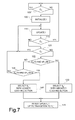
- a current state S K is selected and the state management module 28 performs a test on the condition C 1 until this is verified (block 100, silicon exit).
- the state control module 28 initializes an integrator ( Figure 7 , block 105 ) which calculates the integral I (block 110).
- the test on the condition C 1 (block 115) is then executed once again. If the condition C 1 is verified (block 115, exit YES), the procedure starts again from block 100, otherwise (block 115, exit NO) the state management module 28 performs a test on the condition C 2 , to check if the integral I is comprised between the negative threshold TH L and the positive threshold TH H ( Figure 7 , block 120, Figure 8 ). If affirmative ( Figure 7 , block 120, exit YES), the value of the integral I is updated (block 110) and the test on the condition C 1 (block 115) is repeated.
- the state control module 28 performs a test on the concordance between the sign of the error of pressure E P and the sign of the derivative of the absolute pressure P A (block 125). If the error of pressure E P and the derivative of the absolute pressure P A are both positive (block 125, exit YES), the state control module 28 selects a new state S K ', to which corresponds a higher cooling action of the condenser 8 compared to the current status S K (block 130). In this case, in fact, the absolute pressure P A is greater than the reference pressure P R and is increasing (positive derivative). Therefore, also the magnitude of the error of pressure E P grows and it is necessary to increase heat dispersion by way of increased ventilation. The magnitude of the cooling action is determined by the number of active fans F IJ and their speed.
- the state control module 28 performs an additional test on the concordance between the sign of the error of pressure E P and the sign of the derivative of the absolute pressure P A (block 135).
- the state control module 28 selects a new state S K ', which corresponds to a lower cooling action of the condenser 8 (block 140).
- the absolute pressure P A is in fact lesser than the reference pressure P R and is also diminishing (negative derivative). Therefore, the amplitude (absolute value) of the error of pressure E P grows and is necessary to reduce the heat dispersion by way of lesser ventilation.
- the state management module 28 inhibits the updating of the integral until the transition to the new state S K ' is completed (block 145). Therefore, the updating of the integral I is once again permitted, and the procedure ends.
- the drive module 30 receives a request to modify the state of the condenser 8 switching to state S K ', to which corresponds a different cooling action, and acts upon the fans F IJ in order to bring them under the operating conditions corresponding to the state S K '.
- the procedure to actuate the change of state is performed as shown in Figure 9 .
- the drive module 30 Upon receipt of the request to bring the condenser 8 from the current state S K to the new state S K ' (block 200), the drive module 30 selects the fans F IJ whose operating conditions must be modified (block 205) and determines the order for intervention upon the selected fans F IJ (block 210).
- the selection can be simply made by comparing the rows of the table 31 of Figure 6 corresponding to the states S K and S K '. Similarly, the final operating conditions are determined for each fan that has to change modes.
- the order of intervention upon the fans F IJ is however preferably determined so as to turn on the first fans belonging to the secondary modules ("dephlegmators") of the condenser 8 with respect to those belonging to primary modules and in general maintaining as much as possible the heat exchange conditions uniform throughout the entire condenser 8.
- first to be modified is the speed of fans F IJ placed in even positions in the central paths ST 1 , ST 2 , ..., ST M and gradually the others.
- the drive module 30 puts them in function in sequence according to the speed shown in Table 31. More specifically, the drive module 30 simultaneously starts groups of no more than N MAX of fans F IJ and interpose a start-up time range T S between the start of a group of fans F IJ and the next (N MAX is the maximum number of fans F IJ that can be started at the same time without overloading the transformers 24, 25).
- the drive module 30 then intervenes upon the already active fans F IJ , of which speed R 1 , ..., R L needs to be changed.
- a number of fans F IJ not greater than N MAX are stopped (block 220), while the others remain functioning in unchanged operating conditions.
- the stopped fans F IJ are reactivated at a speed R 1 , ..., R L required in the new state S K ' (block 230).
- the rest time T R can be shorter when a transition of a fan F IJ is required at a higher speed R 1 , ..., R L than a transition at a lower speed R 1 , ..., R L .
- the rest time is related to the demagnetization time of motors M IJ , so as to allow the correct demagnetization.
- the drive module 30 notifies the state management module 28 that the transition to the new state S K ' has been completed (block 240).
- block 235, exit NO a new group of no more than N MAX fans F IJ and is stopped (block 220) to be restarted at a speed R 1 , ..., R L provided for the new state S K ' (block 230), after the rest time T R (block 225) elapses.
- Figure 10 shows a procedure used by the state management module 28 in an alternative embodiment of the invention.
- a safety band B S is defined around the value of the reference pressure P R , comprising and being wider than the dead band B E (see also Figure 8 ).
- the state management module 28 cyclically monitors the condition C 1 (block 100).
- the control module 28 initializes the integrator (block 105) and performs a test on the condition C 0 (block 150).
- the value of the integration constant K I is determined by the outcome of the test.
- assigned to the integration constant K I is an initial value of integration K IL (block 155), if the condition C 0 is verified (block 150, exit YES), and a second value of integration K IH (block 160), greater than the first value of integration K IL , on the contrary (block 150, exit NO).
- Figure 11 illustrates a procedure performed by the state management module 28 in a further embodiment of the invention. Also in this case, a test is executed on the condition C 0 as defined above (block 175), after the integrator is initialized (block 105). If the absolute pressure P A is within the safety band B S (block 175, exit YES), the procedure continues as described with reference to Figure 9 , with the tests on conditions C1, C2 and on the concordance of sign of the error of pressure E P and derivative of the absolute pressure P A (blocks 115, 120, 125, 135). If, on the contrary, the absolute pressure P A exceeds the security band B S (Block 175, exit NO), a new state S K ' is immediately selected, depending on whether the error of pressure E P is positive or negative.
- the state control module 28 selects a new state S K ', which corresponds to a higher cooling action of the condenser 8 (block 130). If instead the error of pressure E P is negative (block 180, exit NO), the state control module 28 selects a new state S K ', which corresponds to a lower cooling action of the condenser 8 (block 140).
- the invention can be advantageously applied to any type of plant based on a steam turbine, such as plants in a "single-shaft” configuration (with gas turbine and steam turbine coupled to the same shaft), and in a "2+1" configuration (with two gas turbines).
- the steam turbine may have medium pressure and low pressure separated sections.
Landscapes
- Engineering & Computer Science (AREA)
- Mechanical Engineering (AREA)
- General Engineering & Computer Science (AREA)
- Engine Equipment That Uses Special Cycles (AREA)
- Separation By Low-Temperature Treatments (AREA)
Abstract
Description
- The present invention relates to a control method for an air-cooled condenser of an electric power generation plant with automatic selection of state and to an electric power generation plant.
- As known, the combined cycle plants for generating electric power can have different configurations, according to project needs. In any case, a combined cycle plant comprises at least one gas turbine and a steam turbine, one or more electric generators, a recovery boiler and a condenser.
- The recovery boiler receives hot exhaust gases from the gas turbine and utilizes them for producing steam in appropriate conditions to be supplied to different sections (high, medium and low pressure) of the steam turbine.
- The condenser is generally of the air type (ACC, Air-Cooled Condenser) and condenses the steam deriving from the steam turbine or from by-pass systems with which steam turbines are normally provided, transferring the residual heat into the atmosphere.
- An air-cooled condenser typically comprises a plurality of tube bundle lines, in which the steam flows, and a plurality of fans, organized as a matrix in rows and columns and arranged so as to cool the steam flowing through the tube bundles.
- The major fraction (about 90%) of the steam is condensed into tube bundles thus condensed by means of fans belonging to primary modules and therefore collected, by gravity, into a collection tank. The condensate will then be taken from the collection tank by means of extraction pumps and sent to the recovery boiler. The remaining fraction (about 10%) of the steam is condensed in tube bundles cooled by fans belonging to sub modules and the residual air (non-condensable gases) is conveyed to an air extraction system, to be evacuated into the atmosphere.
- The cooling action required of the condenser naturally varies depending both on the power supplied by the plant (load), and the environmental conditions (pressure and temperature). The intensity of the cooling depends on the number of fans and by their speed, which must be properly controlled. The fans, in particular, can be switched off or operated at constant speed, selected in a set of values.
- The monitoring operations are critical, however, due to the high power absorbed by each fan (often several tens of kilowatts). Turning on a fan, for example, involves the absorption of a high current peak, as well as, although to a lesser extent, the increase in speed. It is possible therefore that overloads may occur for the medium/low voltage transformers that power the motors of the fans. Even when the fan speed is reduced, it is necessary to ensure proper motor demagnetization. The speed variations lead to greater wear on mechanical parts.
- In particular, a problem which affects known control systems is caused by control strategies, that do not adequately account for the evolution of steam conditions and generate requests for speed change too frequently. The critical issues related to the change in operating conditions of the fans reoccur more often than would be effectively needed, increasing the risk of malfunction or breakage.
- The aim of the present invention is therefore to provide a control method for an air-cooled condenser of an electric power generation plant and an electric power generation plant that allows to avoid unnecessary state transitions, without compromising the performance of the condenser.
- Implemented according to the present invention are a method for controlling an air-cooled condenser of an electric power generation plant and an electric power generation plant as defined respectively in
claims - The present invention will now be described with reference to the annexed drawings, which illustrate a non limitative example of an embodiment, in which:
-
Figure 1 is a simplified block diagram of an electric power generation plant incorporating a condenser according to an embodiment of the present invention; -
Figure 2 is a simplified front view of a part of the condenser ofFigure 1 sectioned along the traced plane II-II offigure 4 ; -
Figure 3 is a simplified side view of a part of the condenser ofFigure 1 sectioned along the traced plane III-III offigure 4 ; -
Figure 4 is a simplified plan view from above of part of the condenser offigure 1 ; -
Figure 5 is a simplified block diagram relative to a portion of the condenser offigure 1 ; -
Figure 6 illustrates a table relative to the operation of the condenser offigure 1 ; -
Figure 7 is a flowchart relative to the method steps for controlling an air condenser according to an embodiment of the present invention; -
Figure 8 is a graph that represents magnitudes used in the method steps illustrated inFigure 7 ; -
Figure 9 is a flowchart concerning further method steps offigure 1 ; -
Figure 10 is a flowchart relative to the method steps for controlling an air condenser according to a different embodiment of the present invention; and -
Figure 11 is a flowchart relative to the method steps for controlling an air condenser according to a further embodiment of the present invention. - As shown in
Figure 1 , a combined cycle plant for generating electric power comprises a gas turbine group 2, asteam turbine 3, two alternators, 4, 5, respectively, coupled to the gas turbine 2 and thesteam turbine 3, a recovery boiler 7, which operates as a steam generator, acondenser 8, anacquisition module 9 and acontrol device 10. - The gas turbine group 2 comprises a
compressor 11, which draws a flow rate of air from outside through a suction duct not shown, acombustion chamber 12 and agas turbine 13, coupled to thecombustion chamber 12 to receive and expand a flow rate of exhaust gas. The exhaust gas of gas turbine 2 are conveyed towards the recovery boiler 7 and are used for producing steam. - The
steam turbine 3, which in the described example comprises ahigh pressure section 3a and a medium-low pressure section 3b, receives high pressure steam and low-medium pressure flow rates from the recovery boiler 7 and provides a flow rate of steam to thecondenser 8 through the exhaust of medium-low pressure section 3b and through a by-pass system of a known type and not shown here for simplicity. - The
condenser 8 is of the air type (forced ventilation). Through a controlled flow of forced cooling air, thecondenser 8 cools the steam received by the steam turbine, causing condensation. The flow of cooling air is determined by thecontrol device 10. - The condensed steam is conveyed to a
storage tank 15 and then withdrawn bycondensate extraction pumps 16 to be fed again to the recovery boiler 7. - The
control device 10 has a plurality of processing units, assigned respectively, to the gas turbine control group 2, to thesteam turbine 3, and to thecondenser 8 and cooperating with each other to regulate the power delivered by theplant 1. In particular theprocessing units steam turbine 3 is of a known type and will not be described in detail. Afurther processing unit 20, in charge of the control of thecondenser 8, receives from the acquisition module 9 a pressure signal PA, indicative of the absolute pressure at the inlet of thecondenser 8 and uses it to determine and set appropriate conditions for thecondenser 8. The structure of theprocessing unit 20 and the methods of management of the operating conditions of thecondenser 8 will be later described in detail. -
Figures 2-4 illustrate in simplified form thecondenser 8, which comprises abase 21 and a plurality of fans F11, F12, ..., F1N, F21, F22, ..., F2N, FM1, FM2, ..., FMN (designated in synthesis for this purpose by way of the symbol FIJ), supported by thebase 21. The fans FIJ are disposed as a matrix and are grouped into M side by side lines, also known as "paths" ST1, ST2, ..., STM, of each N fans (for example 7 paths of 6 fans). - Tube bundles 22 (which are shown in
Figure 4 are only hatch indicated, for simplicity), are traversed by the steam coming from thesteam turbine 3 and are arranged along respective paths ST1, ST2, ..., STM, in order to receive air from the fans FIJ. - The fans FIJ are driven by respective motors M11, M12, ..., M1N, M21, M22, ..., M2N, MM1, MM2, ..., MMN (schematically illustrated in
Figure 5 and designated in synthesis for this purpose by way of the symbol MIJ), which are in turn fed by transformers of medium voltage/low voltage. In the non-limitative example here described, there are twotransformers transformer 24; and the motors MIJ of fans FIJ in even-positions in respective paths are fed by thetransformer 25. - With reference once again to
Figure 1 , theprocessing unit 20 assigned to the control of thecondenser 8 comprises areference generator module 26, asubtractor node 27, astate management module 28, amemory module 29 and adrive module 30. - The
reference generator module 26 is programmable in order to provide a reference pressure value PR, indicative of a target steam pressure obtainable at entrance to thecondenser 8. - The
subtractor node 27 determines a pressure error EP on the basis of the difference between the pressure signal PA and the value of reference pressure PR (i.e. EP = PA - PR or, alternatively, EP = K(PA - PR), where K is a constant). The pressure error EP is supplied to thestate management module 28 and used here for determining and changing the operating conditions of the fans FIJ. - The operating conditions of the fans FIJ are encoded using a table 31 contained in the
memory module 29 and illustrated by way of example inFigure 6 . The table 31 has P rows and MxN columns. Each row of the table 31 defines one of H available states S1, ..., SP (in synthesis SK) of thecondenser 8, i.e. a particular configuration of operating conditions of the fans FIJ. Whereas the columns of table 31 define the operating conditions of respective fans FIJ in each state. Therefore, each cell defines the operating conditions of a specific fan FIJ in a specific state of thecondenser 8. - Each fan FIJ can be selectively placed in one of a plurality of operating conditions, which comprise a state of isolation (wherein the fan stopped and the line of tube bundles is intercepted by specific isolation valves, in order to reduce the heat-exchange surface in winter conditions and to avoid, therefore, the formation of ice in the tubes), a condition of natural convection (fan stopped) and a plurality of speed values R1, ..., RQ (for example, expressed in revolutions per minute). In the embodiment described, the fans FIJ are operable at a low speed R1 and at a high speed R2 . For example, the low speed R1 is equal to 75% of the high speed R2.
- In
Figure 6 , the possible operating conditions of the fans FIJ are represented as follows: - N: natural convection (fan stopped)
- R1 : low speed
- R2 : high speed.
- The procedure used by the
state management module 28 will be later described in detail. Practically, thestate management module 28 determines in which state SK thecondenser 8 must be reached or maintained. - A signal indicative of the selected state SK is sent to the
drive module 30, which controls the motors MIJ of the fans FIJ accordingly. In particular, if thestate management module 28 requires a change of state, thedrive module 30 manages the transition to the state SK in order to avoid overloading for thetransformers - With reference to
Figure 7 , the procedure performed by thestate management module 28 is based on the verification of conditions on the pressure error value EP, on its integral I and on the derivative of the absolute pressure PA (represented by way of example inFigure 8 ). If neither of the conditions are verified, thestate management module 28 determines a state change in order to increase or decrease the cooling action of thecondenser 8. - In one embodiment, the following conditions are verified:



- In addition, a further condition is verified relative to the concordance between the sign of the pressure error EP as defined in (EP = PA - PR or EP = K (PA - PR) ) and the sign of the derivative of the absolute pressure PA.
- The parameters αL1, αH1, respectively negative and positive, define in practice a dead band BE around the value zero for the pressure error EP (or, in a completely equivalent way, around the reference pressure value PR for the absolute pressure PA) and are preferably programmable.
- In the expression relative to the condition C2, the integration constant KI determines the rapidity of response of the
state management module 28 and is calibratable, while the parameters THL and THH are respectively a negative threshold and a positive threshold and set a dead band BI around the value zero for the integral I. - Evidently, the above expressed conditions can be explicitly formulated in terms of absolute pressure PA and of the reference pressure value PR:


- Even in this case a further condition is verified relative to the concordance between the sign of the error in pressure EP as defined in (EP = PA - PR or EP = K(PA - PR) ) and the sign of the derivative of the absolute pressure PA.
- Initially (
Figure 7 block 100), a current state SK is selected and thestate management module 28 performs a test on the condition C1 until this is verified (block 100, silicon exit). When the condition C1 is no longer verified, i.e. when the absolute pressure PA exits the dead band BE (Figure 7 , block 100, exit NO,Figure 8 ), thestate control module 28 initializes an integrator (Figure 7 , block 105 ) which calculates the integral I (block 110). - The test on the condition C1 (block 115) is then executed once again. If the condition C1 is verified (block 115, exit YES), the procedure starts again from
block 100, otherwise (block 115, exit NO) thestate management module 28 performs a test on the condition C2, to check if the integral I is comprised between the negative threshold THL and the positive threshold THH (Figure 7 , block 120,Figure 8 ). If affirmative (Figure 7 , block 120, exit YES), the value of the integral I is updated (block 110) and the test on the condition C1 (block 115) is repeated. If the integral I is out of the dead band BI between the negative threshold THL and the positive threshold THH (Figure 7 , block 120, exit NO,Figure 8 ), thestate control module 28 performs a test on the concordance between the sign of the error of pressure EP and the sign of the derivative of the absolute pressure PA (block 125). If the error of pressure EP and the derivative of the absolute pressure PA are both positive (block 125, exit YES), thestate control module 28 selects a new state SK', to which corresponds a higher cooling action of thecondenser 8 compared to the current status SK (block 130). In this case, in fact, the absolute pressure PA is greater than the reference pressure PR and is increasing (positive derivative). Therefore, also the magnitude of the error of pressure EP grows and it is necessary to increase heat dispersion by way of increased ventilation. The magnitude of the cooling action is determined by the number of active fans FIJ and their speed. - On the contrary (block 125, exit NO), the
state control module 28 performs an additional test on the concordance between the sign of the error of pressure EP and the sign of the derivative of the absolute pressure PA (block 135). - In particular, if the error of pressure EP as defined and the derivative of the absolute pressure PA are both negative (block 135, exit YES), the
state control module 28 selects a new state SK', which corresponds to a lower cooling action of the condenser 8 (block 140). The absolute pressure PA is in fact lesser than the reference pressure PR and is also diminishing (negative derivative). Therefore, the amplitude (absolute value) of the error of pressure EP grows and is necessary to reduce the heat dispersion by way of lesser ventilation. - On the contrary (block 135, exit NO), the amplitude (absolute value) error of pressure EP is reducing, since the sign of the error of pressure EP and the sign of the derivative of the absolute pressure PA are not in accordance. In this case, the procedure continues from
block 110, i.e. a new value of the integral I is calculated and the test is repeated on the condition C1 (block 115). - Once the new state SK' is selected, the
state management module 28 inhibits the updating of the integral until the transition to the new state SK' is completed (block 145). Therefore, the updating of the integral I is once again permitted, and the procedure ends. - As mentioned above, the
drive module 30 receives a request to modify the state of thecondenser 8 switching to state SK', to which corresponds a different cooling action, and acts upon the fans FIJ in order to bring them under the operating conditions corresponding to the state SK'. - In one embodiment, the procedure to actuate the change of state is performed as shown in
Figure 9 . - Upon receipt of the request to bring the
condenser 8 from the current state SK to the new state SK' (block 200), thedrive module 30 selects the fans FIJ whose operating conditions must be modified (block 205) and determines the order for intervention upon the selected fans FIJ (block 210). - The selection can be simply made by comparing the rows of the table 31 of
Figure 6 corresponding to the states SK and SK'. Similarly, the final operating conditions are determined for each fan that has to change modes. - The order of intervention upon the fans FIJ is however preferably determined so as to turn on the first fans belonging to the secondary modules ("dephlegmators") of the
condenser 8 with respect to those belonging to primary modules and in general maintaining as much as possible the heat exchange conditions uniform throughout theentire condenser 8. For example, first to be modified is the speed of fans FIJ placed in even positions in the central paths ST1, ST2, ..., STM and gradually the others. - Therefore, if there are fans FIJ that need to be brought to a stopped condition, they are stopped at the same time (block 215). Oppositely, if at this step there are fans FIJ that need to be started from the stopped condition, the
drive module 30 puts them in function in sequence according to the speed shown in Table 31. More specifically, thedrive module 30 simultaneously starts groups of no more than NMAX of fans FIJ and interpose a start-up time range TS between the start of a group of fans FIJ and the next (NMAX is the maximum number of fans FIJ that can be started at the same time without overloading thetransformers 24, 25). - The
drive module 30 then intervenes upon the already active fans FIJ, of which speed R1, ..., RL needs to be changed. A number of fans FIJ not greater than NMAX are stopped (block 220), while the others remain functioning in unchanged operating conditions. After a minimum rest time TR has elapsed (block 225), the stopped fans FIJ are reactivated at a speed R1, ..., RL required in the new state SK' (block 230). The rest time TR can be shorter when a transition of a fan FIJ is required at a higher speed R1, ..., RL than a transition at a lower speed R1, ..., RL. In addition, the rest time is related to the demagnetization time of motors MIJ, so as to allow the correct demagnetization. - If all of the fans FIJ are driven at the expected speed for the new state SK' (block 235, exit YES), the
drive module 30 notifies thestate management module 28 that the transition to the new state SK' has been completed (block 240). On the contrary (block 235, exit NO), a new group of no more than NMAX fans FIJ and is stopped (block 220) to be restarted at a speed R1, ..., RL provided for the new state SK' (block 230), after the rest time TR (block 225) elapses. In this way, practically, while a group of fans FIJ are started at a predefined speed, another group of fans FIJ are stopped. The start-up and shutdown steps of these groups of fans FIJ may be substantially simultaneous. - In this way, it is possible to make a transition between states in reduced time, avoiding however critical situations due to high inrush power absorbed by the fans. In particular, by limiting the number of fans started simultaneously the
transformers -
Figure 10 , wherein equal steps to those already described above are indicated with the same reference numbers, shows a procedure used by thestate management module 28 in an alternative embodiment of the invention. - In this case, in addition to conditions C1, C2 and the concordance condition of sign of error of pressure EP and of the derivative of the absolute pressure PA above indicated, the
state management module 28 utilizes a further condition C0 on the error, defined as follows:
where αL2 ∈ [- 1, αL1] and αH2 ∈ [αH1, 1] (e.g., αL1 = -0.4 and αH1 = 0.4). Practically therefore, a safety band BS is defined around the value of the reference pressure PR, comprising and being wider than the dead band BE (see alsoFigure 8 ). - In the embodiment of
figure 10 , thestate management module 28 cyclically monitors the condition C1 (block 100). When the condition C1 ceases to be verified, thecontrol module 28 initializes the integrator (block 105) and performs a test on the condition C0 (block 150). The value of the integration constant KI is determined by the outcome of the test. In particular, assigned to the integration constant KI is an initial value of integration KIL (block 155), if the condition C0 is verified (block 150, exit YES), and a second value of integration KIH (block 160), greater than the first value of integration KIL, on the contrary (block 150, exit NO). - Practically, if the absolute pressure PA exceeds the safety band BS, the responsiveness of
state management module 28 is increased, so as to promptly cause a change of state. - The procedure then continues as described above, besides the fact that the test on the condition C0 (block 150) and the assignment of the constant of integration (
blocks 155 and 160) are repeated until the situation persists in which the condition C1 is not verified, while the condition C2 and conditions concerning the concordance of sign of the error of pressure EP and of the derivative of the absolute pressure PA are verified. -
Figure 11 illustrates a procedure performed by thestate management module 28 in a further embodiment of the invention. Also in this case, a test is executed on the condition C0 as defined above (block 175), after the integrator is initialized (block 105). If the absolute pressure PA is within the safety band BS (block 175, exit YES), the procedure continues as described with reference toFigure 9 , with the tests on conditions C1, C2 and on the concordance of sign of the error of pressure EP and derivative of the absolute pressure PA (blocks 115, 120, 125, 135). If, on the contrary, the absolute pressure PA exceeds the security band BS (Block 175, exit NO), a new state SK' is immediately selected, depending on whether the error of pressure EP is positive or negative. More precisely, if the error of pressure EP is positive (block 180, exit YES), thestate control module 28 selects a new state SK', which corresponds to a higher cooling action of the condenser 8 (block 130). If instead the error of pressure EP is negative (block 180, exit NO), thestate control module 28 selects a new state SK', which corresponds to a lower cooling action of the condenser 8 (block 140). - It is finally clear that modifications and variations can be made to the method and plant described, without going beyond the scope of the present invention, as defined in the appended claims.
- In particular, the invention can be advantageously applied to any type of plant based on a steam turbine, such as plants in a "single-shaft" configuration (with gas turbine and steam turbine coupled to the same shaft), and in a "2+1" configuration (with two gas turbines).
- In addition, the steam turbine may have medium pressure and low pressure separated sections.
Claims (20)
- Method for controlling an air-cooled condenser of an electric power generation plant, comprising:detecting a control quantity (PA) indicative of conditions of a steam flow supplied to the condenser (8); andon the basis of the detected control quantity (PA) and of a reference value (PR), selecting a state (SK, SK') of the condenser from among a plurality of available states (S1, ..., SP), which correspond to respective modes of a cooling action of the condenser (8);wherein selecting a state (SK, SK') comprises:verifying a first condition (C1), concerning the control quantity (PA) in relation to the reference value (PR);verifying a second condition (C2), concerning an integral of the control quantity (PA) in relation to the reference value (PR);verifying a third condition, concerning a derivative of the control quantity (PA); anddeciding whether to change the selected state (SK, SK') on the basis of the first condition (C1), of the second condition (C2) and of the third condition (C3).
- Method according to claim 1, wherein the first condition (C1) concerns an error (EP) given by a difference between the control quantity (PA) and the reference value (PR).
- Method according to claim 2, wherein the second condition (C2) concerns is an integral of the error (EP).
- Method according to claim 3, wherein the third condition concerns a relation between a sign of the error (EP) and a sign of the derivative of the control quantity (PA).
- Method according to claim 4, wherein deciding whether to change the state (SK, SK') comprises selecting a new state (SK') if:the error (EP) is outside a first dead band (BE), defined by a first proportionality parameter (αL1) and by a second proportionality parameter (αH1); andthe integral of the error (EP) is outside second dead band (BI), defined by a negative threshold (THL) and by a positive threshold (THH);and if, moreover, the control quantity (PA) is greater than the reference value (PR) and the derivative of the control quantity (PA) is positive or else the control quantity (PA) is lower than the reference value (PR) and the derivative of the control quantity (PA) is negative.
- Method according to claim 5, wherein a greater cooling action of the condenser (8) corresponds to the new selected state (SK'), if the control quantity (PA) is greater than the reference value (PR), and a lower cooling action of the condenser (8) corresponds to the new selected state (SK'), if the control quantity (PA) is lower than the reference value (PR).
- Method according to any one of claims from 2 to 6, wherein selecting a state (SK, SK') comprises verifying a fourth condition (C0), concerning the control quantity (PA) in relation to the reference value (PR).
- Method according to claim 7, wherein the integral of the error (EP) is calculated using an integration constant (KI) which is assigned a first integration value (KIL), if the control quantity (PA) is inside a safety band (BS), which includes the first dead band (BE), and a second integration value (KIH), greater than the first integration value (KIL), if the control quantity (PA) is outside the safety band (BS).
- Method according to claim 7, wherein deciding whether to change the state (SK, SK') comprises selecting a new state (SK'), if the control quantity (PA) is outside a safety band (BS), which includes the first dead band (BE).
- Method according to any one of the foregoing claims, wherein the condenser (8) comprises a plurality of fans (FIJ) and wherein the states (SK, SK') of the condenser (8) are defined by sets of speed values (R1, ..., RQ) of the fans (FIJ).
- Method according to claims 5 and 10, wherein selecting a new state (SK') comprises modifying the speed (R1, ..., RQ) of at least on of the fans (FIJ).
- Electric power generation plant comprising:a steam turbine (3);an air-cooled condenser (8), coupled to the steam turbine (3),for receiving steam coming from the steam turbine (3); anda detecting interface (9), configured to detect a control quantity (PA) indicative of conditions of a steam flow supplied to the condenser (8);characterized by a control device (10) configured to:on the basis of the detected control quantity (PA) and of a reference value (PR) , selecting a state (SK, SK') of the condenser form among a plurality of available states (S1, ..., SP), which correspond to respective modes of a cooling action of the condenser (8);verifying a first condition (C1), concerning the control quantity (PA) in relation to the reference value (PR);verifying a second condition (C2), concerning an integral of the control quantity (PA) in relation to the reference value (PR);verifying a third condition, concerning a derivative of the control quantity (PA); anddeciding whether to change the selected state (SK, SK') on the basis of the first condition (C1), of the second condition (C2) and of the third condition (C3).
- Plant according to claim 12, wherein the first condition (C1) concerns an error (EP) given by a difference between the control quantity (PA) and the reference value (PR).
- Plant according to claim 13, wherein the second condition (C2) concerns is an integral of the error (EP).
- Plant according to claim 14, wherein the third condition concerns a relation between a sign of the error (EP) and a sign of the derivative of the control quantity (PA).
- Plant according to claim 15, wherein the control device (10) is further configured to select a new state (SK') if:the error (EP) is outside a first dead band (BE), defined by a first proportionality parameter (αL1) and by a second proportionality parameter (αH1); andthe integral of the error (EP) is outside a second dead band (BI), defined by a negative threshold (THL) and by a positive threshold (THH);and if, moreover, the control quantity (PA) is greater than the reference value (PR) and the derivative of the control quantity (PA) is positive or else the control quantity (PA) is lower than the reference value (PR) and the derivative of the control quantity (PA) is negative.
- Plant according to any one of claims from 12 to 16, wherein the control device (10) is further configured to check a fourth condition (C0), concerning the control quantity (PA) in relation to the reference value (PR).
- Plant according to claim 17, wherein the control device (10) is further configured to calculate the integral of the error (EP) using an integration constant (KI) and assign the integration constant (KI) a first integration value (KIL), if the control quantity (PA) is inside a safety band (BS), which includes the first dead band (BE), and a second integration value (KIH), greater than the first integration value (KIL), if the control quantity (PA) is outside the safety band (BS).
- Plant according to claim 17, wherein the control device (10) is further configured to select a new state (SK'), if the control quantity (PA) is outside a safety band (BS), which includes the first dead band (BE).
- Plant according to any one of claims from 12 to 19, wherein the condenser (8) comprises a plurality of fans (FIJ) and wherein the states (SK, SK') of the condenser (8) are defined by set of speed values (R1, ..., RQ) of the fans (FIJ).
Priority Applications (1)
| Application Number | Priority Date | Filing Date | Title |
|---|---|---|---|
| PL11175886T PL2413077T3 (en) | 2010-07-28 | 2011-07-28 | Control method for an air-cooled condenser of an electric power generation plant with automatic selection of state and electric power generation plant |
Applications Claiming Priority (1)
| Application Number | Priority Date | Filing Date | Title |
|---|---|---|---|
| ITMI2010A001395A IT1401150B1 (en) | 2010-07-28 | 2010-07-28 | METHOD FOR THE CONTROL OF AN AIR CONDENSER OF A PLANT FOR THE PRODUCTION OF ELECTRICITY WITH AUTOMATIC SELECTION OF THE STATE AND PLANT FOR THE PRODUCTION OF ELECTRICITY |
Publications (2)
| Publication Number | Publication Date |
|---|---|
| EP2413077A1 true EP2413077A1 (en) | 2012-02-01 |
| EP2413077B1 EP2413077B1 (en) | 2013-07-03 |
Family
ID=43737745
Family Applications (1)
| Application Number | Title | Priority Date | Filing Date |
|---|---|---|---|
| EP11175886.8A Active EP2413077B1 (en) | 2010-07-28 | 2011-07-28 | Control method for an air-cooled condenser of an electric power generation plant with automatic selection of state and electric power generation plant |
Country Status (3)
| Country | Link |
|---|---|
| EP (1) | EP2413077B1 (en) |
| IT (1) | IT1401150B1 (en) |
| PL (1) | PL2413077T3 (en) |
Citations (5)
| Publication number | Priority date | Publication date | Assignee | Title |
|---|---|---|---|---|
| US4045961A (en) * | 1974-09-09 | 1977-09-06 | The Lummus Company | Control of freezing in air-cooled steam condensers |
| GB2135206A (en) * | 1983-02-14 | 1984-08-30 | Hudson Products Corp | Steam condenser |
| WO1998002701A1 (en) * | 1996-07-17 | 1998-01-22 | Energiagazdálkodási Részvénytársaság | Natural-draught air condenser apparatus and method of operation thereof |
| EP1557622A2 (en) * | 2004-01-22 | 2005-07-27 | Hussmann Corporation | Microchannel condenser assembly |
| EP1624269A2 (en) * | 2003-10-02 | 2006-02-08 | HONDA MOTOR CO., Ltd. | Cooling control device for condenser |
-
2010
- 2010-07-28 IT ITMI2010A001395A patent/IT1401150B1/en active
-
2011
- 2011-07-28 PL PL11175886T patent/PL2413077T3/en unknown
- 2011-07-28 EP EP11175886.8A patent/EP2413077B1/en active Active
Patent Citations (5)
| Publication number | Priority date | Publication date | Assignee | Title |
|---|---|---|---|---|
| US4045961A (en) * | 1974-09-09 | 1977-09-06 | The Lummus Company | Control of freezing in air-cooled steam condensers |
| GB2135206A (en) * | 1983-02-14 | 1984-08-30 | Hudson Products Corp | Steam condenser |
| WO1998002701A1 (en) * | 1996-07-17 | 1998-01-22 | Energiagazdálkodási Részvénytársaság | Natural-draught air condenser apparatus and method of operation thereof |
| EP1624269A2 (en) * | 2003-10-02 | 2006-02-08 | HONDA MOTOR CO., Ltd. | Cooling control device for condenser |
| EP1557622A2 (en) * | 2004-01-22 | 2005-07-27 | Hussmann Corporation | Microchannel condenser assembly |
Also Published As
| Publication number | Publication date |
|---|---|
| ITMI20101395A1 (en) | 2012-01-29 |
| IT1401150B1 (en) | 2013-07-12 |
| PL2413077T3 (en) | 2014-02-28 |
| EP2413077B1 (en) | 2013-07-03 |
Similar Documents
| Publication | Publication Date | Title |
|---|---|---|
| DK2196667T3 (en) | Cooling system for wind turbine components | |
| AU2015258171B2 (en) | Solar thermal power generation system | |
| US20110005225A1 (en) | Electric Power Plant, and Method for Running Electric Power Plant | |
| US20170298866A1 (en) | Method and apparatus for cogeneration power plant waste heat source utilization by incorporated water source high temperature heat pump | |
| KR20120040648A (en) | Heat recovery system | |
| US20160376932A1 (en) | Orc stack-system control | |
| CN102032105A (en) | Method for controlling a wind turbine at high thermal loads | |
| CN106855365A (en) | The air cooling tubes condenser unit of running optimizatin | |
| JP5201183B2 (en) | Air conditioner and method of operating refrigerator | |
| US9453428B2 (en) | Water/steam cycle and method for operating the same | |
| JP2003343211A (en) | Condenser system | |
| EP2413078B1 (en) | Method for controlling an air-cooled condenser of an electric power generation plant with optimized management of state transitions and electric power generation plant | |
| EP2413077B1 (en) | Control method for an air-cooled condenser of an electric power generation plant with automatic selection of state and electric power generation plant | |
| CN205591971U (en) | Air cooling system | |
| US6502401B1 (en) | High pressure bypass sliding setpoint for steam-cooled turbine | |
| JP5790793B2 (en) | Air-cooled condenser and power generator equipped with the same | |
| JP2005273655A (en) | Power generation control method and apparatus | |
| US20100072292A1 (en) | Indoor Space Heating Apparatus | |
| CN205445693U (en) | Steam turbine cooling device and turbo generator unit | |
| CN113062845A (en) | Energy-saving vacuum unit for improving vacuum degree of condenser of thermal power plant | |
| CN119492237B (en) | A method for analyzing energy-saving operation scheme of refrigeration system | |
| RU2458256C2 (en) | Automatic control method of air cooling devices | |
| CN117287375B (en) | Optimized configuration of air compressor unit and compressed air energy storage system | |
| CN105822363A (en) | Air cooling system and control method for air cooling system | |
| CN111831025B (en) | Oil temperature control method of transformer and transformer using same |
Legal Events
| Date | Code | Title | Description |
|---|---|---|---|
| AK | Designated contracting states |
Kind code of ref document: A1 Designated state(s): AL AT BE BG CH CY CZ DE DK EE ES FI FR GB GR HR HU IE IS IT LI LT LU LV MC MK MT NL NO PL PT RO RS SE SI SK SM TR |
|
| AX | Request for extension of the european patent |
Extension state: BA ME |
|
| PUAI | Public reference made under article 153(3) epc to a published international application that has entered the european phase |
Free format text: ORIGINAL CODE: 0009012 |
|
| 17P | Request for examination filed |
Effective date: 20120801 |
|
| RIC1 | Information provided on ipc code assigned before grant |
Ipc: F28B 1/00 20060101AFI20121205BHEP Ipc: F28B 1/06 20060101ALI20121205BHEP |
|
| GRAP | Despatch of communication of intention to grant a patent |
Free format text: ORIGINAL CODE: EPIDOSNIGR1 |
|
| GRAS | Grant fee paid |
Free format text: ORIGINAL CODE: EPIDOSNIGR3 |
|
| GRAA | (expected) grant |
Free format text: ORIGINAL CODE: 0009210 |
|
| AK | Designated contracting states |
Kind code of ref document: B1 Designated state(s): AL AT BE BG CH CY CZ DE DK EE ES FI FR GB GR HR HU IE IS IT LI LT LU LV MC MK MT NL NO PL PT RO RS SE SI SK SM TR |
|
| REG | Reference to a national code |
Ref country code: GB Ref legal event code: FG4D |
|
| REG | Reference to a national code |
Ref country code: AT Ref legal event code: REF Ref document number: 620017 Country of ref document: AT Kind code of ref document: T Effective date: 20130715 Ref country code: CH Ref legal event code: EP |
|
| REG | Reference to a national code |
Ref country code: IE Ref legal event code: FG4D |
|
| REG | Reference to a national code |
Ref country code: DE Ref legal event code: R096 Ref document number: 602011002200 Country of ref document: DE Effective date: 20130829 |
|
| PG25 | Lapsed in a contracting state [announced via postgrant information from national office to epo] |
Ref country code: SI Free format text: LAPSE BECAUSE OF FAILURE TO SUBMIT A TRANSLATION OF THE DESCRIPTION OR TO PAY THE FEE WITHIN THE PRESCRIBED TIME-LIMIT Effective date: 20130703 |
|
| REG | Reference to a national code |
Ref country code: AT Ref legal event code: MK05 Ref document number: 620017 Country of ref document: AT Kind code of ref document: T Effective date: 20130703 |
|
| REG | Reference to a national code |
Ref country code: NL Ref legal event code: VDEP Effective date: 20130703 |
|
| REG | Reference to a national code |
Ref country code: LT Ref legal event code: MG4D |
|
| PG25 | Lapsed in a contracting state [announced via postgrant information from national office to epo] |
Ref country code: NO Free format text: LAPSE BECAUSE OF FAILURE TO SUBMIT A TRANSLATION OF THE DESCRIPTION OR TO PAY THE FEE WITHIN THE PRESCRIBED TIME-LIMIT Effective date: 20131003 Ref country code: SE Free format text: LAPSE BECAUSE OF FAILURE TO SUBMIT A TRANSLATION OF THE DESCRIPTION OR TO PAY THE FEE WITHIN THE PRESCRIBED TIME-LIMIT Effective date: 20130703 Ref country code: BE Free format text: LAPSE BECAUSE OF FAILURE TO SUBMIT A TRANSLATION OF THE DESCRIPTION OR TO PAY THE FEE WITHIN THE PRESCRIBED TIME-LIMIT Effective date: 20130703 Ref country code: AT Free format text: LAPSE BECAUSE OF FAILURE TO SUBMIT A TRANSLATION OF THE DESCRIPTION OR TO PAY THE FEE WITHIN THE PRESCRIBED TIME-LIMIT Effective date: 20130703 Ref country code: HR Free format text: LAPSE BECAUSE OF FAILURE TO SUBMIT A TRANSLATION OF THE DESCRIPTION OR TO PAY THE FEE WITHIN THE PRESCRIBED TIME-LIMIT Effective date: 20130703 Ref country code: IS Free format text: LAPSE BECAUSE OF FAILURE TO SUBMIT A TRANSLATION OF THE DESCRIPTION OR TO PAY THE FEE WITHIN THE PRESCRIBED TIME-LIMIT Effective date: 20131103 Ref country code: LT Free format text: LAPSE BECAUSE OF FAILURE TO SUBMIT A TRANSLATION OF THE DESCRIPTION OR TO PAY THE FEE WITHIN THE PRESCRIBED TIME-LIMIT Effective date: 20130703 Ref country code: PT Free format text: LAPSE BECAUSE OF FAILURE TO SUBMIT A TRANSLATION OF THE DESCRIPTION OR TO PAY THE FEE WITHIN THE PRESCRIBED TIME-LIMIT Effective date: 20131104 Ref country code: CY Free format text: LAPSE BECAUSE OF FAILURE TO SUBMIT A TRANSLATION OF THE DESCRIPTION OR TO PAY THE FEE WITHIN THE PRESCRIBED TIME-LIMIT Effective date: 20130807 |
|
| PG25 | Lapsed in a contracting state [announced via postgrant information from national office to epo] |
Ref country code: ES Free format text: LAPSE BECAUSE OF FAILURE TO SUBMIT A TRANSLATION OF THE DESCRIPTION OR TO PAY THE FEE WITHIN THE PRESCRIBED TIME-LIMIT Effective date: 20131014 Ref country code: GR Free format text: LAPSE BECAUSE OF FAILURE TO SUBMIT A TRANSLATION OF THE DESCRIPTION OR TO PAY THE FEE WITHIN THE PRESCRIBED TIME-LIMIT Effective date: 20131004 Ref country code: LV Free format text: LAPSE BECAUSE OF FAILURE TO SUBMIT A TRANSLATION OF THE DESCRIPTION OR TO PAY THE FEE WITHIN THE PRESCRIBED TIME-LIMIT Effective date: 20130703 Ref country code: FI Free format text: LAPSE BECAUSE OF FAILURE TO SUBMIT A TRANSLATION OF THE DESCRIPTION OR TO PAY THE FEE WITHIN THE PRESCRIBED TIME-LIMIT Effective date: 20130703 Ref country code: NL Free format text: LAPSE BECAUSE OF FAILURE TO SUBMIT A TRANSLATION OF THE DESCRIPTION OR TO PAY THE FEE WITHIN THE PRESCRIBED TIME-LIMIT Effective date: 20130703 |
|
| REG | Reference to a national code |
Ref country code: PL Ref legal event code: T3 |
|
| PG25 | Lapsed in a contracting state [announced via postgrant information from national office to epo] |
Ref country code: CY Free format text: LAPSE BECAUSE OF FAILURE TO SUBMIT A TRANSLATION OF THE DESCRIPTION OR TO PAY THE FEE WITHIN THE PRESCRIBED TIME-LIMIT Effective date: 20130703 |
|
| REG | Reference to a national code |
Ref country code: IE Ref legal event code: MM4A |
|
| REG | Reference to a national code |
Ref country code: DE Ref legal event code: R119 Ref document number: 602011002200 Country of ref document: DE Effective date: 20140201 |
|
| PG25 | Lapsed in a contracting state [announced via postgrant information from national office to epo] |
Ref country code: DE Free format text: LAPSE BECAUSE OF NON-PAYMENT OF DUE FEES Effective date: 20140201 Ref country code: RO Free format text: LAPSE BECAUSE OF FAILURE TO SUBMIT A TRANSLATION OF THE DESCRIPTION OR TO PAY THE FEE WITHIN THE PRESCRIBED TIME-LIMIT Effective date: 20130703 Ref country code: CZ Free format text: LAPSE BECAUSE OF FAILURE TO SUBMIT A TRANSLATION OF THE DESCRIPTION OR TO PAY THE FEE WITHIN THE PRESCRIBED TIME-LIMIT Effective date: 20130703 Ref country code: SK Free format text: LAPSE BECAUSE OF FAILURE TO SUBMIT A TRANSLATION OF THE DESCRIPTION OR TO PAY THE FEE WITHIN THE PRESCRIBED TIME-LIMIT Effective date: 20130703 Ref country code: EE Free format text: LAPSE BECAUSE OF FAILURE TO SUBMIT A TRANSLATION OF THE DESCRIPTION OR TO PAY THE FEE WITHIN THE PRESCRIBED TIME-LIMIT Effective date: 20130703 Ref country code: DK Free format text: LAPSE BECAUSE OF FAILURE TO SUBMIT A TRANSLATION OF THE DESCRIPTION OR TO PAY THE FEE WITHIN THE PRESCRIBED TIME-LIMIT Effective date: 20130703 Ref country code: MC Free format text: LAPSE BECAUSE OF FAILURE TO SUBMIT A TRANSLATION OF THE DESCRIPTION OR TO PAY THE FEE WITHIN THE PRESCRIBED TIME-LIMIT Effective date: 20130703 |
|
| PLBE | No opposition filed within time limit |
Free format text: ORIGINAL CODE: 0009261 |
|
| STAA | Information on the status of an ep patent application or granted ep patent |
Free format text: STATUS: NO OPPOSITION FILED WITHIN TIME LIMIT |
|
| PG25 | Lapsed in a contracting state [announced via postgrant information from national office to epo] |
Ref country code: IT Free format text: LAPSE BECAUSE OF FAILURE TO SUBMIT A TRANSLATION OF THE DESCRIPTION OR TO PAY THE FEE WITHIN THE PRESCRIBED TIME-LIMIT Effective date: 20130703 |
|
| 26N | No opposition filed |
Effective date: 20140404 |
|
| REG | Reference to a national code |
Ref country code: FR Ref legal event code: ST Effective date: 20140509 |
|
| PG25 | Lapsed in a contracting state [announced via postgrant information from national office to epo] |
Ref country code: IE Free format text: LAPSE BECAUSE OF NON-PAYMENT OF DUE FEES Effective date: 20130728 |
|
| PG25 | Lapsed in a contracting state [announced via postgrant information from national office to epo] |
Ref country code: FR Free format text: LAPSE BECAUSE OF NON-PAYMENT OF DUE FEES Effective date: 20130903 |
|
| REG | Reference to a national code |
Ref country code: CH Ref legal event code: PL |
|
| PG25 | Lapsed in a contracting state [announced via postgrant information from national office to epo] |
Ref country code: CH Free format text: LAPSE BECAUSE OF NON-PAYMENT OF DUE FEES Effective date: 20140731 Ref country code: LI Free format text: LAPSE BECAUSE OF NON-PAYMENT OF DUE FEES Effective date: 20140731 |
|
| PG25 | Lapsed in a contracting state [announced via postgrant information from national office to epo] |
Ref country code: SM Free format text: LAPSE BECAUSE OF FAILURE TO SUBMIT A TRANSLATION OF THE DESCRIPTION OR TO PAY THE FEE WITHIN THE PRESCRIBED TIME-LIMIT Effective date: 20130703 |
|
| PG25 | Lapsed in a contracting state [announced via postgrant information from national office to epo] |
Ref country code: MT Free format text: LAPSE BECAUSE OF FAILURE TO SUBMIT A TRANSLATION OF THE DESCRIPTION OR TO PAY THE FEE WITHIN THE PRESCRIBED TIME-LIMIT Effective date: 20130703 |
|
| PG25 | Lapsed in a contracting state [announced via postgrant information from national office to epo] |
Ref country code: HU Free format text: LAPSE BECAUSE OF FAILURE TO SUBMIT A TRANSLATION OF THE DESCRIPTION OR TO PAY THE FEE WITHIN THE PRESCRIBED TIME-LIMIT; INVALID AB INITIO Effective date: 20110728 Ref country code: LU Free format text: LAPSE BECAUSE OF NON-PAYMENT OF DUE FEES Effective date: 20130728 Ref country code: BG Free format text: LAPSE BECAUSE OF FAILURE TO SUBMIT A TRANSLATION OF THE DESCRIPTION OR TO PAY THE FEE WITHIN THE PRESCRIBED TIME-LIMIT Effective date: 20130703 Ref country code: MK Free format text: LAPSE BECAUSE OF FAILURE TO SUBMIT A TRANSLATION OF THE DESCRIPTION OR TO PAY THE FEE WITHIN THE PRESCRIBED TIME-LIMIT Effective date: 20130703 Ref country code: RS Free format text: LAPSE BECAUSE OF FAILURE TO SUBMIT A TRANSLATION OF THE DESCRIPTION OR TO PAY THE FEE WITHIN THE PRESCRIBED TIME-LIMIT Effective date: 20131003 |
|
| GBPC | Gb: european patent ceased through non-payment of renewal fee |
Effective date: 20150728 |
|
| PG25 | Lapsed in a contracting state [announced via postgrant information from national office to epo] |
Ref country code: GB Free format text: LAPSE BECAUSE OF NON-PAYMENT OF DUE FEES Effective date: 20150728 |
|
| PGFP | Annual fee paid to national office [announced via postgrant information from national office to epo] |
Ref country code: PL Payment date: 20160530 Year of fee payment: 6 |
|
| PG25 | Lapsed in a contracting state [announced via postgrant information from national office to epo] |
Ref country code: AL Free format text: LAPSE BECAUSE OF FAILURE TO SUBMIT A TRANSLATION OF THE DESCRIPTION OR TO PAY THE FEE WITHIN THE PRESCRIBED TIME-LIMIT Effective date: 20130703 |
|
| PG25 | Lapsed in a contracting state [announced via postgrant information from national office to epo] |
Ref country code: PL Free format text: LAPSE BECAUSE OF NON-PAYMENT OF DUE FEES Effective date: 20170728 |
|
| P01 | Opt-out of the competence of the unified patent court (upc) registered |
Effective date: 20240430 |
|
| PGFP | Annual fee paid to national office [announced via postgrant information from national office to epo] |
Ref country code: TR Payment date: 20250724 Year of fee payment: 15 |