EP2413072A2 - Method of manufacturing damper assembly of refrigerator - Google Patents
Method of manufacturing damper assembly of refrigerator Download PDFInfo
- Publication number
- EP2413072A2 EP2413072A2 EP11174717A EP11174717A EP2413072A2 EP 2413072 A2 EP2413072 A2 EP 2413072A2 EP 11174717 A EP11174717 A EP 11174717A EP 11174717 A EP11174717 A EP 11174717A EP 2413072 A2 EP2413072 A2 EP 2413072A2
- Authority
- EP
- European Patent Office
- Prior art keywords
- case
- closing plate
- thermal insulating
- insulating material
- damper assembly
- Prior art date
- Legal status (The legal status is an assumption and is not a legal conclusion. Google has not performed a legal analysis and makes no representation as to the accuracy of the status listed.)
- Granted
Links
Images



Classifications
-
- F—MECHANICAL ENGINEERING; LIGHTING; HEATING; WEAPONS; BLASTING
- F25—REFRIGERATION OR COOLING; COMBINED HEATING AND REFRIGERATION SYSTEMS; HEAT PUMP SYSTEMS; MANUFACTURE OR STORAGE OF ICE; LIQUEFACTION SOLIDIFICATION OF GASES
- F25D—REFRIGERATORS; COLD ROOMS; ICE-BOXES; COOLING OR FREEZING APPARATUS NOT OTHERWISE PROVIDED FOR
- F25D17/00—Arrangements for circulating cooling fluids; Arrangements for circulating gas, e.g. air, within refrigerated spaces
- F25D17/04—Arrangements for circulating cooling fluids; Arrangements for circulating gas, e.g. air, within refrigerated spaces for circulating air, e.g. by convection
- F25D17/06—Arrangements for circulating cooling fluids; Arrangements for circulating gas, e.g. air, within refrigerated spaces for circulating air, e.g. by convection by forced circulation
- F25D17/08—Arrangements for circulating cooling fluids; Arrangements for circulating gas, e.g. air, within refrigerated spaces for circulating air, e.g. by convection by forced circulation using ducts
-
- B—PERFORMING OPERATIONS; TRANSPORTING
- B29—WORKING OF PLASTICS; WORKING OF SUBSTANCES IN A PLASTIC STATE IN GENERAL
- B29C—SHAPING OR JOINING OF PLASTICS; SHAPING OF MATERIAL IN A PLASTIC STATE, NOT OTHERWISE PROVIDED FOR; AFTER-TREATMENT OF THE SHAPED PRODUCTS, e.g. REPAIRING
- B29C44/00—Shaping by internal pressure generated in the material, e.g. swelling or foaming ; Producing porous or cellular expanded plastics articles
- B29C44/02—Shaping by internal pressure generated in the material, e.g. swelling or foaming ; Producing porous or cellular expanded plastics articles for articles of definite length, i.e. discrete articles
- B29C44/12—Incorporating or moulding on preformed parts, e.g. inserts or reinforcements
- B29C44/18—Filling preformed cavities
-
- F—MECHANICAL ENGINEERING; LIGHTING; HEATING; WEAPONS; BLASTING
- F25—REFRIGERATION OR COOLING; COMBINED HEATING AND REFRIGERATION SYSTEMS; HEAT PUMP SYSTEMS; MANUFACTURE OR STORAGE OF ICE; LIQUEFACTION SOLIDIFICATION OF GASES
- F25C—PRODUCING, WORKING OR HANDLING ICE
- F25C5/00—Working or handling ice
- F25C5/20—Distributing ice
- F25C5/22—Distributing ice particularly adapted for household refrigerators
-
- F—MECHANICAL ENGINEERING; LIGHTING; HEATING; WEAPONS; BLASTING
- F25—REFRIGERATION OR COOLING; COMBINED HEATING AND REFRIGERATION SYSTEMS; HEAT PUMP SYSTEMS; MANUFACTURE OR STORAGE OF ICE; LIQUEFACTION SOLIDIFICATION OF GASES
- F25D—REFRIGERATORS; COLD ROOMS; ICE-BOXES; COOLING OR FREEZING APPARATUS NOT OTHERWISE PROVIDED FOR
- F25D23/00—General constructional features
- F25D23/06—Walls
-
- F—MECHANICAL ENGINEERING; LIGHTING; HEATING; WEAPONS; BLASTING
- F25—REFRIGERATION OR COOLING; COMBINED HEATING AND REFRIGERATION SYSTEMS; HEAT PUMP SYSTEMS; MANUFACTURE OR STORAGE OF ICE; LIQUEFACTION SOLIDIFICATION OF GASES
- F25D—REFRIGERATORS; COLD ROOMS; ICE-BOXES; COOLING OR FREEZING APPARATUS NOT OTHERWISE PROVIDED FOR
- F25D23/00—General constructional features
- F25D23/06—Walls
- F25D23/061—Walls with conduit means
-
- F—MECHANICAL ENGINEERING; LIGHTING; HEATING; WEAPONS; BLASTING
- F25—REFRIGERATION OR COOLING; COMBINED HEATING AND REFRIGERATION SYSTEMS; HEAT PUMP SYSTEMS; MANUFACTURE OR STORAGE OF ICE; LIQUEFACTION SOLIDIFICATION OF GASES
- F25D—REFRIGERATORS; COLD ROOMS; ICE-BOXES; COOLING OR FREEZING APPARATUS NOT OTHERWISE PROVIDED FOR
- F25D23/00—General constructional features
- F25D23/06—Walls
- F25D23/062—Walls defining a cabinet
- F25D23/064—Walls defining a cabinet formed by moulding, e.g. moulding in situ
-
- F—MECHANICAL ENGINEERING; LIGHTING; HEATING; WEAPONS; BLASTING
- F25—REFRIGERATION OR COOLING; COMBINED HEATING AND REFRIGERATION SYSTEMS; HEAT PUMP SYSTEMS; MANUFACTURE OR STORAGE OF ICE; LIQUEFACTION SOLIDIFICATION OF GASES
- F25D—REFRIGERATORS; COLD ROOMS; ICE-BOXES; COOLING OR FREEZING APPARATUS NOT OTHERWISE PROVIDED FOR
- F25D2317/00—Details or arrangements for circulating cooling fluids; Details or arrangements for circulating gas, e.g. air, within refrigerated spaces, not provided for in other groups of this subclass
- F25D2317/06—Details or arrangements for circulating cooling fluids; Details or arrangements for circulating gas, e.g. air, within refrigerated spaces, not provided for in other groups of this subclass with forced air circulation
- F25D2317/061—Details or arrangements for circulating cooling fluids; Details or arrangements for circulating gas, e.g. air, within refrigerated spaces, not provided for in other groups of this subclass with forced air circulation through special compartments
-
- F—MECHANICAL ENGINEERING; LIGHTING; HEATING; WEAPONS; BLASTING
- F25—REFRIGERATION OR COOLING; COMBINED HEATING AND REFRIGERATION SYSTEMS; HEAT PUMP SYSTEMS; MANUFACTURE OR STORAGE OF ICE; LIQUEFACTION SOLIDIFICATION OF GASES
- F25D—REFRIGERATORS; COLD ROOMS; ICE-BOXES; COOLING OR FREEZING APPARATUS NOT OTHERWISE PROVIDED FOR
- F25D2317/00—Details or arrangements for circulating cooling fluids; Details or arrangements for circulating gas, e.g. air, within refrigerated spaces, not provided for in other groups of this subclass
- F25D2317/06—Details or arrangements for circulating cooling fluids; Details or arrangements for circulating gas, e.g. air, within refrigerated spaces, not provided for in other groups of this subclass with forced air circulation
- F25D2317/066—Details or arrangements for circulating cooling fluids; Details or arrangements for circulating gas, e.g. air, within refrigerated spaces, not provided for in other groups of this subclass with forced air circulation characterised by the air supply
- F25D2317/0666—Details or arrangements for circulating cooling fluids; Details or arrangements for circulating gas, e.g. air, within refrigerated spaces, not provided for in other groups of this subclass with forced air circulation characterised by the air supply from the freezer
Definitions
- the present disclosure relates to the field of refrigerators.
- An embodiment relates to a method of manufacturing a damper assembly that constitutes a refrigerator and that opens and closes a water or ice dispensing hole to prevent the leakage of cool air.
- Refrigerators are electric appliances for storage at low temperature in a storing space closed by a door. Refrigerators may store different types of things, but for convenience the stored items will be referred to herein as "food"
- the storing space is cooled with cool air that exchanges heat with refrigerant circulating in refrigeration cycles, thereby optimally storing food.
- a refrigerator may include a dispenser for dispensing ice made by an ice maker, without opening a door of the refrigerator.
- Such a dispenser is installed on an exterior part of a refrigerator door, and dispenses ice made by an ice maker in a refrigerator, according to a user's operation.
- the dispenser includes a recess recessed inward from the front surface of the refrigerator door.
- a container for receiving ice is placed in the recess, and an ice dispensing button or lever is manipulated to dispense the ice.
- Ice made by the ice maker is stored in an ice bank, and the ice is dispensed through a discharge duct communicating with the ice bank and the dispenser, when the ice dispensing button or lever is manipulated.
- a damper assembly is installed on an end of the discharge duct near the dispenser to selectively open the end when the ice dispensing button or lever is manipulated.
- the damper assembly Since the damper assembly is connected to the ice bank through the discharge duct, the damper assembly is required to have sealing and insulating performances, thereby preventing ice from being molten in the ice bank and preventing cool air from leaking out of a freezing compartment.
- a method of manufacturing a damper assembly of a refrigerator and configured to open and close a discharge duct for discharging ice from a dispenser of a refrigerator door includes: molding a case forming the appearance of the damper assembly and having an open surface; inserting the case in a jig and filling the case with a thermal insulating material to blow and mold the thermal insulating material; and coupling a closing plate to the case to cover the open surface of the case, the closing plate contacting the discharge duct when the damper assembly closes the discharge duct.
- the thermal insulating material may include polyurethane.
- the thermal insulating material may be blown and entirely fill an inside of the case such that the thermal insulating material is flush with the open surface of the case.
- the closing plate may include a thermoplastic elastomer (TPE).
- TPE thermoplastic elastomer
- the closing plate may include an elastic deformable material.
- the coupling of the closing plate may include fixing the molded closing plate to the open surface of the case filled with the blown thermal insulating material.
- the closing plate may be fixed using an adhesive fixes to an end of the thermal insulating material and the case.
- the closing plate may be press-fit coupled in a fixing recess disposed along a front end of the case.
- the coupling of the closing plate may include inserting the case filled with the blown thermal insulating material into a mold to integrally form the closing plate with the case through insert injection molding.
- the closing plate may be closely fixed to both a front surface of the thermal insulating material and a front end of the case.
- a fixing recess may be recessed in a front end of the case, an insertion part may be disposed on a rear surface of the closing plate to correspond to the fixing recess, and the insertion part may be inserted in the fixing recess.
- a sealing part protruding forward may surround the closing plate.
- Fig. 1 is a perspective view illustrating a refrigerator door including a dispenser according to an embodiment.
- Fig. 2 is a cut-away perspective view taken along line I-I' of Fig. 1 .
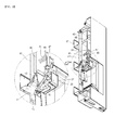
- Fig. 3 is a perspective view illustrating a state in which a damper assembly opens an outlet end of a discharge duct according to an embodiment.
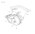
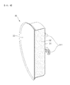
- Fig. 4 is a perspective view illustrating a damper assembly according to an embodiment.
- Fig. 5 is an exploded perspective view illustrating the damper assembly of Fig. 4 .
- Fig. 6 is a cut-away perspective view taken along line II-II' of Fig. 4 .
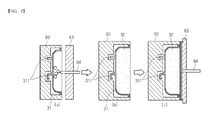
- Figs. 7A to 7C are cross-sectional views illustrating a process of manufacturing the damper assembly of Fig. 4 .
- Fig. 1 is a perspective view illustrating a refrigerator door including a dispenser according to an embodiment.
- a door 10 includes: an outer cover 11 constituting an appearance of the door 10; a door liner 12 coupled to the rear portion of the outer cover 11, and a thermal insulating member (not shown) filling a space between the outer cover 11 and the door liner 12.
- a recess is recessed a predetermined depth in the front surface of the door 10.
- a dispenser 20 is disposed in the recess.
- the dispenser 20 is recessed rearward to form a space receiving a container that contains ice or water.
- the dispenser 20 includes a housing 21 disposed in the recess of the door 10.
- the housing 21 may include a bottom surface, a wall including left, right, and rear surfaces extending upward from the bottom surface, and a top surface connecting top ends of the wall to one another.
- the dispenser 20 may include: a tray 26 that is removably coupled to or is drawable from the bottom surface of the housing 21; an ice dispensing button 25 that is installed on the rear surface of the housing 21; an ice chute 24 that extends downward from the top surface of the housing 21; and a water dispensing button 23 disposed in front of the ice chute 24.
- a water dispensing hole (not shown) is disposed in the top surface of the housing 21, particularly, in the top surface in front of the water dispensing button 23, and is connected to a water supply pipe (not shown) that is inserted in the door 10.
- the dispenser 20 is provided with a control panel 22 to manipulate the dispenser 20 and check an operation of the dispenser 20. Dispensing of ice from a freezing compartment by the dispenser 20 will be described later.
- Fig. 2 is a cut-away perspective view taken along line I-I' of Fig. 1 .
- the rear portion of the door 10 is provided with an ice making compartment 48.
- an ice maker 43 and an ice bank 44 are disposed in the ice making compartment 48.
- the ice maker 43 makes ice from water supplied to the ice making compartment 48.
- the ice bank 44 is disposed under the ice maker 43 to store the ice made by the ice maker 43.
- An ice making assembly includes the ice making compartment 48, the ice maker 43, and the ice bank 44.
- a first end of the discharge duct 50 communicates with the ice bank 44, and a second end thereof communicates with the top surface of the housing 21 and is exposed to the outside. Ice in the ice bank 44 may be molten by external air introduced to the ice bank 44 through the second end of the discharge duct 50 or by heat transfer due to a temperature difference between the inside and outside of the discharge duct 50.
- a damper assembly 30 closes the second end of the discharge duct 50 to prevent the ice from being molten. The damper assembly 30 opens and closes the second end of the discharge duct 50 to selectively discharge ice from the ice bank 44.
- the ice bank 44 is provided with a mechanism for transferring and/or crushing ice.
- the mechanism includes an auger 45 pressing ice from the ice bank 44 to the discharge duct 50, and a motor 47 driving the auger 45.
- the motor 47 rotates the auger 45 to supply ice to the discharge duct 50.
- the damper assembly 30 selectively opening and closing the second end of the discharge duct 50, and a method of manufacturing the damper assembly 30 will now be described with reference to the accompanying drawings.
- Fig. 3 is a perspective view illustrating a state in which a damper assembly opens an outlet end of a discharge duct according to an embodiment.
- the damper assembly 30 closing the second end (also called an outlet end) of the discharge duct 50 may rotate about a rotation shaft 52 connected to the damper assembly 30, to open the outlet end.
- Fig. 4 is a perspective view illustrating a damper assembly according to an embodiment.
- Fig. 5 is an exploded perspective view illustrating the damper assembly of Fig. 4 .
- Fig. 6 is a cut-away perspective view taken along line II-II' of Fig. 4 .
- the damper assembly 30 includes a closing plate 33, a thermal insulating member 32, and a case 31.
- the closing plate 33 closes the outlet end of the discharge duct 50 to prevent ice from being discharged.
- the closing plate 33 is inserted in the discharge duct 50 such that the outer surface of the closing plate 33 closely contacts the inner surface of the discharge duct 50 to close the discharge duct 50. Accordingly, the inside of the discharge duct 50 can be reliably maintained at low temperature.
- the closing plate 33 may be formed of a deformable soft material such as silicone, rubber, or synthetic resin.
- the closing plate 33 may have a larger area than that of the thermal insulating member 32 or the case 31 to more reliably contact the discharge duct 50. Accordingly, when the discharge duct 50 is closed, cool air is prevented from leaking out of the discharge duct 50. Since the closing plate 33 is formed of a deformable soft material, when the ice dispensing button 25 is manipulated to dispense ice, the closing plate 33 smoothly slides along the inner surface of the discharge duct 50, thereby facilitating opening and closing of the discharge duct 50.
- a sealing part 331 surrounds the closing plate 33.
- the sealing part 331 entirely surrounds the closing plate 33, and is inclined forward (to the left side of Fig. 6 ).
- the sealing part 331 may be larger than an opening of the discharge duct 50 to closely contact the discharge duct 50.
- the closing plate 33 may include an insertion part 332 on the rear surface thereof.
- the insertion part 332 may be disposed at a position to correspond to a fixing recess 312 to be described later, and may protrude to be inserted in the fixing recess 312. Accordingly, the closing plate 33 can be fixed to the front end of the case 31.
- the contact area between the closing plate 33 and the case 31 may be increased to more stably fix the closing plate 33 to the case 31.
- a surface of the closing plate 33 is provided with the case 31 that includes support protrusions 311 to receive the rotation shaft 52.
- the support protrusions 311 are disposed on an exposed surface of the case 31, and thus, can be coupled to the rotation shaft 52 that is rotated according to a user's manipulation.
- driving force is transmitted to the rotation shaft 52 to open and close the discharge duct 50.
- the fixing recess 312 is disposed along an open boundary surface of the case 31, that is, along the front end of the case 31.
- the fixing recess 312 is recessed inward, and has a size to receive the insertion part 332.
- the thermal insulating member 32 is disposed between the closing plate 33 and the case 31.
- the thermal insulating member 32 is formed by filling a foam material the space between the closing plate 33 and the case 31 to prevent heat transfer due to a temperature difference between the inside and outside of the discharge duct 50, thereby maintaining the inside of the discharge duct 50 at low temperature.
- the thermal insulating member 32 may be formed of a material having low thermal conductivity, such as polyurethane foam.
- Figs. 7A to 7C are cross-sectional views illustrating a process of manufacturing the damper assembly of Fig. 4 .
- the case 31 including the support protrusions 311 may be is inserted into a first mold 60, and liquid or gel of an insulating material having low thermal conductivity, such as polyurethane foam, may be injected into the case 31 by an injector 64, and be blown. Accordingly, the case 31 is integrally formed with the thermal insulating member 32.
- an insulating material having low thermal conductivity such as polyurethane foam
- the closing plate 33 which is separately manufactured, is coupled to a surface of the thermal insulating member 32.
- any coupling member such as an adhesive, a rivet, or a bolt may be used. Accordingly, the damper assembly 30 including the case 31, the thermal insulating member 32, and the closing plate 33 is manufactured.
- the closing plate 33 may be integrally formed with the case 31 and the thermal insulating member 32.
- the case 31 integrally formed with the thermal insulating member 32 is inserted into a third mold 62, and then, a soft material such as silicone, rubber, or synthetic resin, used to form the closing plate 33 is injected between the third mold 62 and a fourth mold 63.
- a soft material such as silicone, rubber, or synthetic resin, used to form the closing plate 33 is injected between the third mold 62 and a fourth mold 63.
- the closing plate 33 can be integrally formed with the case 31 and the thermal insulating member 32, without separately manufacturing the closing plate 33.
- a material used to form the closing plate 33 is not limited to the above-described materials.
- thermal insulating member is blown in the case and is integrally formed with the case, or the thermal insulating member integrally formed with the case is integrally formed with the closing plate, dimension stability thereof can be further improved than that of a method of separately forming a thermal insulating member, a case, and a closing plate, and assembling them.
- sealing and insulating performances of the damper assembly are improved to increase the efficiency of a refrigerator, thereby saving power consumption.
Landscapes
- Engineering & Computer Science (AREA)
- Physics & Mathematics (AREA)
- Mechanical Engineering (AREA)
- Thermal Sciences (AREA)
- General Engineering & Computer Science (AREA)
- Chemical & Material Sciences (AREA)
- Combustion & Propulsion (AREA)
- Cold Air Circulating Systems And Constructional Details In Refrigerators (AREA)
- Refrigerator Housings (AREA)
Abstract
Description
- The present disclosure relates to the field of refrigerators. An embodiment relates to a method of manufacturing a damper assembly that constitutes a refrigerator and that opens and closes a water or ice dispensing hole to prevent the leakage of cool air.
- Refrigerators are electric appliances for storage at low temperature in a storing space closed by a door. Refrigerators may store different types of things, but for convenience the stored items will be referred to herein as "food" The storing space is cooled with cool air that exchanges heat with refrigerant circulating in refrigeration cycles, thereby optimally storing food.
- Along with the change of people's eating patterns and preferences, large and multifunctional refrigerators have been introduced, and various comfortable structures have been added to refrigerators. For example, a refrigerator may include a dispenser for dispensing ice made by an ice maker, without opening a door of the refrigerator.
- Such a dispenser is installed on an exterior part of a refrigerator door, and dispenses ice made by an ice maker in a refrigerator, according to a user's operation. The dispenser includes a recess recessed inward from the front surface of the refrigerator door. A container for receiving ice is placed in the recess, and an ice dispensing button or lever is manipulated to dispense the ice.
- Ice made by the ice maker is stored in an ice bank, and the ice is dispensed through a discharge duct communicating with the ice bank and the dispenser, when the ice dispensing button or lever is manipulated. A damper assembly is installed on an end of the discharge duct near the dispenser to selectively open the end when the ice dispensing button or lever is manipulated.
- Since the damper assembly is connected to the ice bank through the discharge duct, the damper assembly is required to have sealing and insulating performances, thereby preventing ice from being molten in the ice bank and preventing cool air from leaking out of a freezing compartment.
- In one embodiment, a method of manufacturing a damper assembly of a refrigerator and configured to open and close a discharge duct for discharging ice from a dispenser of a refrigerator door includes: molding a case forming the appearance of the damper assembly and having an open surface; inserting the case in a jig and filling the case with a thermal insulating material to blow and mold the thermal insulating material; and coupling a closing plate to the case to cover the open surface of the case, the closing plate contacting the discharge duct when the damper assembly closes the discharge duct.
- The thermal insulating material may include polyurethane.
- The thermal insulating material may be blown and entirely fill an inside of the case such that the thermal insulating material is flush with the open surface of the case.
- The closing plate may include a thermoplastic elastomer (TPE).
- The closing plate may include an elastic deformable material.
- The coupling of the closing plate may include fixing the molded closing plate to the open surface of the case filled with the blown thermal insulating material.
- The closing plate may be fixed using an adhesive fixes to an end of the thermal insulating material and the case.
- The closing plate may be press-fit coupled in a fixing recess disposed along a front end of the case.
- The coupling of the closing plate may include inserting the case filled with the blown thermal insulating material into a mold to integrally form the closing plate with the case through insert injection molding.
- The closing plate may be closely fixed to both a front surface of the thermal insulating material and a front end of the case.
- A fixing recess may be recessed in a front end of the case, an insertion part may be disposed on a rear surface of the closing plate to correspond to the fixing recess, and the insertion part may be inserted in the fixing recess.
- A sealing part protruding forward may surround the closing plate.
- Details of one or more embodiments are set forth in the accompanying drawings and the description below. Other features will be apparent from the description and drawings, and from the claims.
-
Fig. 1 is a perspective view illustrating a refrigerator door including a dispenser according to an embodiment. -
Fig. 2 is a cut-away perspective view taken along line I-I' ofFig. 1 . -
Fig. 3 is a perspective view illustrating a state in which a damper assembly opens an outlet end of a discharge duct according to an embodiment. -
Fig. 4 is a perspective view illustrating a damper assembly according to an embodiment. -
Fig. 5 is an exploded perspective view illustrating the damper assembly ofFig. 4 . -
Fig. 6 is a cut-away perspective view taken along line II-II' ofFig. 4 . -
Figs. 7A to 7C are cross-sectional views illustrating a process of manufacturing the damper assembly ofFig. 4 . - Reference will now be made in detail to the preferred embodiments of the present disclosure, examples of which are illustrated in the accompanying drawings.
-
Fig. 1 is a perspective view illustrating a refrigerator door including a dispenser according to an embodiment. - Referring to
Fig. 1 , adoor 10 according to the current embodiment includes: anouter cover 11 constituting an appearance of thedoor 10; adoor liner 12 coupled to the rear portion of theouter cover 11, and a thermal insulating member (not shown) filling a space between theouter cover 11 and thedoor liner 12. - A recess is recessed a predetermined depth in the front surface of the
door 10. Adispenser 20 is disposed in the recess. Thedispenser 20 is recessed rearward to form a space receiving a container that contains ice or water. In detail, thedispenser 20 includes ahousing 21 disposed in the recess of thedoor 10. Thehousing 21 may include a bottom surface, a wall including left, right, and rear surfaces extending upward from the bottom surface, and a top surface connecting top ends of the wall to one another. - The
dispenser 20 may include: atray 26 that is removably coupled to or is drawable from the bottom surface of thehousing 21; anice dispensing button 25 that is installed on the rear surface of thehousing 21; anice chute 24 that extends downward from the top surface of thehousing 21; and awater dispensing button 23 disposed in front of theice chute 24. A water dispensing hole (not shown) is disposed in the top surface of thehousing 21, particularly, in the top surface in front of thewater dispensing button 23, and is connected to a water supply pipe (not shown) that is inserted in thedoor 10. - When the ice dispensing
button 25 is pressed, ice is dispensed from theice chute 24. Thedispenser 20 is provided with acontrol panel 22 to manipulate thedispenser 20 and check an operation of thedispenser 20. Dispensing of ice from a freezing compartment by thedispenser 20 will be described later. -
Fig. 2 is a cut-away perspective view taken along line I-I' ofFig. 1 . - Referring to
Fig. 2 , the rear portion of thedoor 10 is provided with anice making compartment 48. In detail, anice maker 43 and anice bank 44 are disposed in theice making compartment 48. Theice maker 43 makes ice from water supplied to theice making compartment 48. Theice bank 44 is disposed under theice maker 43 to store the ice made by theice maker 43. An ice making assembly includes theice making compartment 48, theice maker 43, and theice bank 44. When theice dispensing button 25 provided to thedispenser 20 is pressed, ice is discharged through adischarge duct 50 communicating with theice bank 44. - A first end of the
discharge duct 50 communicates with theice bank 44, and a second end thereof communicates with the top surface of thehousing 21 and is exposed to the outside. Ice in theice bank 44 may be molten by external air introduced to theice bank 44 through the second end of thedischarge duct 50 or by heat transfer due to a temperature difference between the inside and outside of thedischarge duct 50. Adamper assembly 30 closes the second end of thedischarge duct 50 to prevent the ice from being molten. Thedamper assembly 30 opens and closes the second end of thedischarge duct 50 to selectively discharge ice from theice bank 44. - The
ice bank 44 is provided with a mechanism for transferring and/or crushing ice. The mechanism includes anauger 45 pressing ice from theice bank 44 to thedischarge duct 50, and amotor 47 driving theauger 45. Themotor 47 rotates theauger 45 to supply ice to thedischarge duct 50. - The
damper assembly 30 selectively opening and closing the second end of thedischarge duct 50, and a method of manufacturing thedamper assembly 30 will now be described with reference to the accompanying drawings. -
Fig. 3 is a perspective view illustrating a state in which a damper assembly opens an outlet end of a discharge duct according to an embodiment. - Referring to
Fig. 3 , when theice dispensing button 25 is pressed, thedamper assembly 30 closing the second end (also called an outlet end) of thedischarge duct 50 may rotate about arotation shaft 52 connected to thedamper assembly 30, to open the outlet end. -
Fig. 4 is a perspective view illustrating a damper assembly according to an embodiment.Fig. 5 is an exploded perspective view illustrating the damper assembly ofFig. 4 .Fig. 6 is a cut-away perspective view taken along line II-II' ofFig. 4 . - Referring to
Figs. 4 and6 , thedamper assembly 30 includes aclosing plate 33, a thermal insulatingmember 32, and acase 31. - The closing
plate 33 closes the outlet end of thedischarge duct 50 to prevent ice from being discharged. The closingplate 33 is inserted in thedischarge duct 50 such that the outer surface of theclosing plate 33 closely contacts the inner surface of thedischarge duct 50 to close thedischarge duct 50. Accordingly, the inside of thedischarge duct 50 can be reliably maintained at low temperature. To this end, the closingplate 33 may be formed of a deformable soft material such as silicone, rubber, or synthetic resin. - Referring to
Fig. 4 , the closingplate 33 may have a larger area than that of the thermal insulatingmember 32 or thecase 31 to more reliably contact thedischarge duct 50. Accordingly, when thedischarge duct 50 is closed, cool air is prevented from leaking out of thedischarge duct 50. Since theclosing plate 33 is formed of a deformable soft material, when theice dispensing button 25 is manipulated to dispense ice, the closingplate 33 smoothly slides along the inner surface of thedischarge duct 50, thereby facilitating opening and closing of thedischarge duct 50. - A sealing part 331 surrounds the
closing plate 33. The sealing part 331 entirely surrounds theclosing plate 33, and is inclined forward (to the left side ofFig. 6 ). The sealing part 331 may be larger than an opening of thedischarge duct 50 to closely contact thedischarge duct 50. - The closing
plate 33 may include an insertion part 332 on the rear surface thereof. The insertion part 332 may be disposed at a position to correspond to a fixing recess 312 to be described later, and may protrude to be inserted in the fixing recess 312. Accordingly, the closingplate 33 can be fixed to the front end of thecase 31. The contact area between the closingplate 33 and thecase 31 may be increased to more stably fix theclosing plate 33 to thecase 31. - A surface of the
closing plate 33 is provided with thecase 31 that includessupport protrusions 311 to receive therotation shaft 52. The support protrusions 311 are disposed on an exposed surface of thecase 31, and thus, can be coupled to therotation shaft 52 that is rotated according to a user's manipulation. When theice dispensing button 25 is pressed, driving force is transmitted to therotation shaft 52 to open and close thedischarge duct 50. - The fixing recess 312 is disposed along an open boundary surface of the
case 31, that is, along the front end of thecase 31. The fixing recess 312 is recessed inward, and has a size to receive the insertion part 332. - The thermal insulating
member 32 is disposed between the closingplate 33 and thecase 31. The thermal insulatingmember 32 is formed by filling a foam material the space between the closingplate 33 and thecase 31 to prevent heat transfer due to a temperature difference between the inside and outside of thedischarge duct 50, thereby maintaining the inside of thedischarge duct 50 at low temperature. The thermal insulatingmember 32 may be formed of a material having low thermal conductivity, such as polyurethane foam. -
Figs. 7A to 7C are cross-sectional views illustrating a process of manufacturing the damper assembly ofFig. 4 . - The
case 31 including thesupport protrusions 311 may be is inserted into afirst mold 60, and liquid or gel of an insulating material having low thermal conductivity, such as polyurethane foam, may be injected into thecase 31 by aninjector 64, and be blown. Accordingly, thecase 31 is integrally formed with the thermal insulatingmember 32. - Then, the closing
plate 33, which is separately manufactured, is coupled to a surface of the thermal insulatingmember 32. To this end, any coupling member such as an adhesive, a rivet, or a bolt may be used. Accordingly, thedamper assembly 30 including thecase 31, the thermal insulatingmember 32, and theclosing plate 33 is manufactured. - Instead of separately manufacturing the
closing plate 33, the closingplate 33 may be integrally formed with thecase 31 and the thermal insulatingmember 32. To this end, thecase 31 integrally formed with the thermal insulatingmember 32 is inserted into athird mold 62, and then, a soft material such as silicone, rubber, or synthetic resin, used to form theclosing plate 33 is injected between thethird mold 62 and a fourth mold 63. Thus, the closingplate 33 can be integrally formed with thecase 31 and the thermal insulatingmember 32, without separately manufacturing theclosing plate 33. A material used to form theclosing plate 33 is not limited to the above-described materials. - The following effects can be obtained using the method of manufacturing the damper assembly according to the above embodiments.
- Firstly, since the thermal insulating member is blown in the case and is integrally formed with the case, or the thermal insulating member integrally formed with the case is integrally formed with the closing plate, dimension stability thereof can be further improved than that of a method of separately forming a thermal insulating member, a case, and a closing plate, and assembling them.
- Secondly, sealing and insulating performances of the damper assembly are improved to increase the efficiency of a refrigerator, thereby saving power consumption.
- Thirdly, since the parts constituting the damper assembly are integrally formed, a process of assembling the damper assembly can be simplified.
- Although embodiments have been described with reference to a number of illustrative embodiments thereof, it should be understood that numerous other modifications and embodiments can be devised by those skilled in the art that will fall within the scope of the appended claims.
Claims (12)
- A method of manufacturing a damper assembly constituting a refrigerator and configured to open and close a discharge duct for discharging ice from a dispenser of a refrigerator door, the method comprising:molding a case constituting an appearance of the damper assembly and having an open surface;inserting the case in a jig and filling the case with a thermal insulating material to blow and mold the thermal insulating material; andcoupling a closing plate to the case to cover the open surface of the case, the closing plate contacting the discharge duct when the damper assembly closes the discharge duct.
- The method according to claim 1, wherein the thermal insulating material comprises polyurethane.
- The method according to claim 1, wherein the thermal insulating material is blown and entirely fills an inside of the case such that the thermal insulating material is flush with the open surface of the case.
- The method according to claim 1, wherein the closing plate comprises a thermoplastic elastomer (TPE).
- The method according to claim 1, wherein the closing plate comprises an elastic deformable material.
- The method according to claim 1, wherein the coupling of the closing plate comprises fixing the molded closing plate to the open surface of the case filled with the blown thermal insulating material.
- The method according to claim 6, wherein the closing plate is fixed using an adhesive fixes to an end of the thermal insulating material and the case.
- The method according to claim 6, wherein the closing plate is press-fit coupled in a fixing recess disposed along a front end of the case.
- The method according to claim 1, wherein the coupling of the closing plate comprises inserting the case filled with the blown thermal insulating material into a mold to integrally form the closing plate with the case through insert injection molding.
- The method according to claim 9, wherein the closing plate is closely fixed to both a front surface of the thermal insulating material and a front end of the case.
- The method according to claim 9, wherein a fixing recess is recessed in a front end of the case,
an insertion part is disposed on a rear surface of the closing plate to correspond to the fixing recess, and
the insertion part is inserted in the fixing recess. - The method according to claim 9, wherein a sealing part protruding forward surrounds the closing plate.
Applications Claiming Priority (1)
| Application Number | Priority Date | Filing Date | Title |
|---|---|---|---|
| KR1020100073774A KR101794346B1 (en) | 2010-07-30 | 2010-07-30 | Method for manufacturing damper assembly |
Publications (3)
| Publication Number | Publication Date |
|---|---|
| EP2413072A2 true EP2413072A2 (en) | 2012-02-01 |
| EP2413072A3 EP2413072A3 (en) | 2018-01-24 |
| EP2413072B1 EP2413072B1 (en) | 2022-10-26 |
Family
ID=44582257
Family Applications (1)
| Application Number | Title | Priority Date | Filing Date |
|---|---|---|---|
| EP11174717.6A Active EP2413072B1 (en) | 2010-07-30 | 2011-07-20 | Method of manufacturing a damper assembly of a refrigerator |
Country Status (4)
| Country | Link |
|---|---|
| US (1) | US8808599B2 (en) |
| EP (1) | EP2413072B1 (en) |
| KR (1) | KR101794346B1 (en) |
| CN (1) | CN102441995A (en) |
Families Citing this family (12)
| Publication number | Priority date | Publication date | Assignee | Title |
|---|---|---|---|---|
| EP2788695B1 (en) | 2011-12-09 | 2019-09-18 | Electrolux Home Products, Inc. | Single paddle ice and water dispenser |
| KR101966043B1 (en) * | 2012-06-12 | 2019-04-05 | 엘지전자 주식회사 | Refrigerator |
| US9169652B2 (en) * | 2012-10-24 | 2015-10-27 | Certainteed Corporation | System, method and apparatus for manufactured building panel |
| USD809671S1 (en) | 2013-10-22 | 2018-02-06 | Certainteed Corporation | Manufactured siding panel with frame |
| US20160350669A1 (en) * | 2015-06-01 | 2016-12-01 | Linkedin Corporation | Blending content pools into content feeds |
| EP3690366B1 (en) | 2015-08-31 | 2022-06-08 | LG Electronics Inc. | Refrigerator |
| KR20170119864A (en) * | 2016-04-20 | 2017-10-30 | 동부대우전자 주식회사 | Dispenser module and refrigerator including the same |
| KR102473297B1 (en) * | 2016-05-04 | 2022-12-01 | 엘지전자 주식회사 | A cap for ice extracting duct, a module thereof and a refrigerator having the same |
| CN112129035B (en) * | 2019-06-25 | 2022-07-26 | 青岛海尔电冰箱有限公司 | Ice discharging device and refrigerator with same |
| US20220113075A1 (en) * | 2020-10-13 | 2022-04-14 | Haier Us Appliance Solutions, Inc. | Ice dispensing motor assembly with separate enclosures with minimized internal volume |
| CN115854620A (en) * | 2021-09-23 | 2023-03-28 | 青岛海尔电冰箱有限公司 | Ice outlet device, refrigerator door body assembly and refrigerator |
| KR20240051627A (en) * | 2022-10-13 | 2024-04-22 | 엘지전자 주식회사 | Refrigerator |
Family Cites Families (12)
| Publication number | Priority date | Publication date | Assignee | Title |
|---|---|---|---|---|
| US3420729A (en) * | 1965-05-14 | 1969-01-07 | Arthur H Roberts | Molded hollow plastic articles of manufacture rigidified with rigid resinous compositions and process for their manufacture |
| US4209999A (en) * | 1978-06-12 | 1980-07-01 | General Electric Company | Household refrigerator with through-the-door ice service |
| US5074770A (en) * | 1989-08-30 | 1991-12-24 | Intellex Corporation | Integrated vacuum forming/reaction injection molding apparatus for manufacturing a shaped polymeric laminate article |
| CN2091283U (en) | 1991-03-11 | 1991-12-25 | 天津市第八塑料制品厂 | Full plastics incubator |
| IT1252217B (en) * | 1991-12-16 | 1995-06-05 | Devi Spa | PROCEDURE AND MACHINE FOR THE MOLDING OF COUPLED PLASTIC MATERIAL. |
| JP3284001B2 (en) * | 1994-06-10 | 2002-05-20 | 株式会社イノアックコーポレーション | Method for producing plastic molded article having foam with skin on surface |
| JP3734587B2 (en) * | 1997-03-14 | 2006-01-11 | 本田技研工業株式会社 | Polypropylene resin outer plate and method for producing the same |
| KR100565622B1 (en) | 2003-09-19 | 2006-03-30 | 엘지전자 주식회사 | Refrigerator |
| CN1663769A (en) | 2004-03-04 | 2005-09-07 | 德洋产业株式会社 | Joint structure for partial foaming part of instrument panel |
| DE202006013708U1 (en) * | 2006-09-07 | 2006-11-09 | BSH Bosch und Siemens Hausgeräte GmbH | Cooling appliance such as an ice or cold water dispenser having a dispensing niche illuminated by a light emitting diode |
| KR20080043598A (en) * | 2006-11-14 | 2008-05-19 | 엘지전자 주식회사 | Ice Extractor for Refrigerator |
| DE202007010238U1 (en) * | 2007-07-24 | 2007-09-20 | BSH Bosch und Siemens Hausgeräte GmbH | Refrigeration device with output flap |
-
2010
- 2010-07-30 KR KR1020100073774A patent/KR101794346B1/en not_active Expired - Fee Related
-
2011
- 2011-07-20 EP EP11174717.6A patent/EP2413072B1/en active Active
- 2011-07-25 US US13/189,717 patent/US8808599B2/en active Active
- 2011-07-29 CN CN2011102648706A patent/CN102441995A/en active Pending
Non-Patent Citations (1)
| Title |
|---|
| None |
Also Published As
| Publication number | Publication date |
|---|---|
| KR20120011997A (en) | 2012-02-09 |
| EP2413072A3 (en) | 2018-01-24 |
| KR101794346B1 (en) | 2017-11-06 |
| EP2413072B1 (en) | 2022-10-26 |
| US20120025418A1 (en) | 2012-02-02 |
| US8808599B2 (en) | 2014-08-19 |
| CN102441995A (en) | 2012-05-09 |
Similar Documents
| Publication | Publication Date | Title |
|---|---|---|
| US8808599B2 (en) | Method of manufacturing damper assembly of refrigerator | |
| US8042353B2 (en) | Refrigerator door having a splash guide | |
| CN102933925B (en) | refrigerator with ice maker | |
| US8844311B2 (en) | Refrigerator with a water and ice dispenser having an improved ice chute air seal | |
| US8434318B2 (en) | Refrigerator | |
| AU2013206714B2 (en) | Refrigerator | |
| US8353179B2 (en) | Refrigerator | |
| KR101997259B1 (en) | Refrigerator | |
| CN103245160B (en) | For refrigerator door and there is this refrigerator | |
| KR102615047B1 (en) | Refrigerator | |
| KR20180007450A (en) | Refrigerator | |
| CN101231084B (en) | Installation structure for ice maker of refrigerator door | |
| US20260002721A1 (en) | Refrigerator comprising fixing part | |
| KR100743748B1 (en) | Ice Maker Installation Structure of Refrigerator Door | |
| JP2005180908A (en) | Refrigerator with automatic ice maker | |
| US20250230963A1 (en) | Ice maker and refrigerator | |
| EP4603770A1 (en) | Refrigerator | |
| KR20070093611A (en) | Refrigerator dispenser | |
| KR20230053108A (en) | Ice maker and refrigerator including the same | |
| KR20210029498A (en) | Ice maker |
Legal Events
| Date | Code | Title | Description |
|---|---|---|---|
| 17P | Request for examination filed |
Effective date: 20110720 |
|
| AK | Designated contracting states |
Kind code of ref document: A2 Designated state(s): AL AT BE BG CH CY CZ DE DK EE ES FI FR GB GR HR HU IE IS IT LI LT LU LV MC MK MT NL NO PL PT RO RS SE SI SK SM TR |
|
| AX | Request for extension of the european patent |
Extension state: BA ME |
|
| PUAI | Public reference made under article 153(3) epc to a published international application that has entered the european phase |
Free format text: ORIGINAL CODE: 0009012 |
|
| RAP1 | Party data changed (applicant data changed or rights of an application transferred) |
Owner name: LG ELECTRONICS INC. |
|
| PUAL | Search report despatched |
Free format text: ORIGINAL CODE: 0009013 |
|
| AK | Designated contracting states |
Kind code of ref document: A3 Designated state(s): AL AT BE BG CH CY CZ DE DK EE ES FI FR GB GR HR HU IE IS IT LI LT LU LV MC MK MT NL NO PL PT RO RS SE SI SK SM TR |
|
| AX | Request for extension of the european patent |
Extension state: BA ME |
|
| RIC1 | Information provided on ipc code assigned before grant |
Ipc: B29C 44/18 20060101ALI20171219BHEP Ipc: F25C 5/00 20180101AFI20171219BHEP |
|
| STAA | Information on the status of an ep patent application or granted ep patent |
Free format text: STATUS: EXAMINATION IS IN PROGRESS |
|
| 17Q | First examination report despatched |
Effective date: 20200312 |
|
| GRAP | Despatch of communication of intention to grant a patent |
Free format text: ORIGINAL CODE: EPIDOSNIGR1 |
|
| STAA | Information on the status of an ep patent application or granted ep patent |
Free format text: STATUS: GRANT OF PATENT IS INTENDED |
|
| INTG | Intention to grant announced |
Effective date: 20220525 |
|
| GRAS | Grant fee paid |
Free format text: ORIGINAL CODE: EPIDOSNIGR3 |
|
| GRAA | (expected) grant |
Free format text: ORIGINAL CODE: 0009210 |
|
| STAA | Information on the status of an ep patent application or granted ep patent |
Free format text: STATUS: THE PATENT HAS BEEN GRANTED |
|
| AK | Designated contracting states |
Kind code of ref document: B1 Designated state(s): AL AT BE BG CH CY CZ DE DK EE ES FI FR GB GR HR HU IE IS IT LI LT LU LV MC MK MT NL NO PL PT RO RS SE SI SK SM TR |
|
| REG | Reference to a national code |
Ref country code: GB Ref legal event code: FG4D |
|
| REG | Reference to a national code |
Ref country code: CH Ref legal event code: EP |
|
| REG | Reference to a national code |
Ref country code: DE Ref legal event code: R096 Ref document number: 602011073390 Country of ref document: DE |
|
| REG | Reference to a national code |
Ref country code: AT Ref legal event code: REF Ref document number: 1527293 Country of ref document: AT Kind code of ref document: T Effective date: 20221115 |
|
| REG | Reference to a national code |
Ref country code: IE Ref legal event code: FG4D |
|
| REG | Reference to a national code |
Ref country code: LT Ref legal event code: MG9D |
|
| REG | Reference to a national code |
Ref country code: NL Ref legal event code: MP Effective date: 20221026 |
|
| REG | Reference to a national code |
Ref country code: AT Ref legal event code: MK05 Ref document number: 1527293 Country of ref document: AT Kind code of ref document: T Effective date: 20221026 |
|
| PG25 | Lapsed in a contracting state [announced via postgrant information from national office to epo] |
Ref country code: NL Free format text: LAPSE BECAUSE OF FAILURE TO SUBMIT A TRANSLATION OF THE DESCRIPTION OR TO PAY THE FEE WITHIN THE PRESCRIBED TIME-LIMIT Effective date: 20221026 |
|
| PG25 | Lapsed in a contracting state [announced via postgrant information from national office to epo] |
Ref country code: SE Free format text: LAPSE BECAUSE OF FAILURE TO SUBMIT A TRANSLATION OF THE DESCRIPTION OR TO PAY THE FEE WITHIN THE PRESCRIBED TIME-LIMIT Effective date: 20221026 Ref country code: PT Free format text: LAPSE BECAUSE OF FAILURE TO SUBMIT A TRANSLATION OF THE DESCRIPTION OR TO PAY THE FEE WITHIN THE PRESCRIBED TIME-LIMIT Effective date: 20230227 Ref country code: NO Free format text: LAPSE BECAUSE OF FAILURE TO SUBMIT A TRANSLATION OF THE DESCRIPTION OR TO PAY THE FEE WITHIN THE PRESCRIBED TIME-LIMIT Effective date: 20230126 Ref country code: LT Free format text: LAPSE BECAUSE OF FAILURE TO SUBMIT A TRANSLATION OF THE DESCRIPTION OR TO PAY THE FEE WITHIN THE PRESCRIBED TIME-LIMIT Effective date: 20221026 Ref country code: FI Free format text: LAPSE BECAUSE OF FAILURE TO SUBMIT A TRANSLATION OF THE DESCRIPTION OR TO PAY THE FEE WITHIN THE PRESCRIBED TIME-LIMIT Effective date: 20221026 Ref country code: ES Free format text: LAPSE BECAUSE OF FAILURE TO SUBMIT A TRANSLATION OF THE DESCRIPTION OR TO PAY THE FEE WITHIN THE PRESCRIBED TIME-LIMIT Effective date: 20221026 Ref country code: AT Free format text: LAPSE BECAUSE OF FAILURE TO SUBMIT A TRANSLATION OF THE DESCRIPTION OR TO PAY THE FEE WITHIN THE PRESCRIBED TIME-LIMIT Effective date: 20221026 |
|
| PG25 | Lapsed in a contracting state [announced via postgrant information from national office to epo] |
Ref country code: RS Free format text: LAPSE BECAUSE OF FAILURE TO SUBMIT A TRANSLATION OF THE DESCRIPTION OR TO PAY THE FEE WITHIN THE PRESCRIBED TIME-LIMIT Effective date: 20221026 Ref country code: PL Free format text: LAPSE BECAUSE OF FAILURE TO SUBMIT A TRANSLATION OF THE DESCRIPTION OR TO PAY THE FEE WITHIN THE PRESCRIBED TIME-LIMIT Effective date: 20221026 Ref country code: LV Free format text: LAPSE BECAUSE OF FAILURE TO SUBMIT A TRANSLATION OF THE DESCRIPTION OR TO PAY THE FEE WITHIN THE PRESCRIBED TIME-LIMIT Effective date: 20221026 Ref country code: IS Free format text: LAPSE BECAUSE OF FAILURE TO SUBMIT A TRANSLATION OF THE DESCRIPTION OR TO PAY THE FEE WITHIN THE PRESCRIBED TIME-LIMIT Effective date: 20230226 Ref country code: HR Free format text: LAPSE BECAUSE OF FAILURE TO SUBMIT A TRANSLATION OF THE DESCRIPTION OR TO PAY THE FEE WITHIN THE PRESCRIBED TIME-LIMIT Effective date: 20221026 Ref country code: GR Free format text: LAPSE BECAUSE OF FAILURE TO SUBMIT A TRANSLATION OF THE DESCRIPTION OR TO PAY THE FEE WITHIN THE PRESCRIBED TIME-LIMIT Effective date: 20230127 |
|
| REG | Reference to a national code |
Ref country code: DE Ref legal event code: R097 Ref document number: 602011073390 Country of ref document: DE |
|
| PG25 | Lapsed in a contracting state [announced via postgrant information from national office to epo] |
Ref country code: SM Free format text: LAPSE BECAUSE OF FAILURE TO SUBMIT A TRANSLATION OF THE DESCRIPTION OR TO PAY THE FEE WITHIN THE PRESCRIBED TIME-LIMIT Effective date: 20221026 Ref country code: RO Free format text: LAPSE BECAUSE OF FAILURE TO SUBMIT A TRANSLATION OF THE DESCRIPTION OR TO PAY THE FEE WITHIN THE PRESCRIBED TIME-LIMIT Effective date: 20221026 Ref country code: EE Free format text: LAPSE BECAUSE OF FAILURE TO SUBMIT A TRANSLATION OF THE DESCRIPTION OR TO PAY THE FEE WITHIN THE PRESCRIBED TIME-LIMIT Effective date: 20221026 Ref country code: DK Free format text: LAPSE BECAUSE OF FAILURE TO SUBMIT A TRANSLATION OF THE DESCRIPTION OR TO PAY THE FEE WITHIN THE PRESCRIBED TIME-LIMIT Effective date: 20221026 Ref country code: CZ Free format text: LAPSE BECAUSE OF FAILURE TO SUBMIT A TRANSLATION OF THE DESCRIPTION OR TO PAY THE FEE WITHIN THE PRESCRIBED TIME-LIMIT Effective date: 20221026 |
|
| PG25 | Lapsed in a contracting state [announced via postgrant information from national office to epo] |
Ref country code: SK Free format text: LAPSE BECAUSE OF FAILURE TO SUBMIT A TRANSLATION OF THE DESCRIPTION OR TO PAY THE FEE WITHIN THE PRESCRIBED TIME-LIMIT Effective date: 20221026 Ref country code: AL Free format text: LAPSE BECAUSE OF FAILURE TO SUBMIT A TRANSLATION OF THE DESCRIPTION OR TO PAY THE FEE WITHIN THE PRESCRIBED TIME-LIMIT Effective date: 20221026 |
|
| PLBE | No opposition filed within time limit |
Free format text: ORIGINAL CODE: 0009261 |
|
| STAA | Information on the status of an ep patent application or granted ep patent |
Free format text: STATUS: NO OPPOSITION FILED WITHIN TIME LIMIT |
|
| 26N | No opposition filed |
Effective date: 20230727 |
|
| PG25 | Lapsed in a contracting state [announced via postgrant information from national office to epo] |
Ref country code: SI Free format text: LAPSE BECAUSE OF FAILURE TO SUBMIT A TRANSLATION OF THE DESCRIPTION OR TO PAY THE FEE WITHIN THE PRESCRIBED TIME-LIMIT Effective date: 20221026 |
|
| PG25 | Lapsed in a contracting state [announced via postgrant information from national office to epo] |
Ref country code: MC Free format text: LAPSE BECAUSE OF FAILURE TO SUBMIT A TRANSLATION OF THE DESCRIPTION OR TO PAY THE FEE WITHIN THE PRESCRIBED TIME-LIMIT Effective date: 20221026 |
|
| PG25 | Lapsed in a contracting state [announced via postgrant information from national office to epo] |
Ref country code: MC Free format text: LAPSE BECAUSE OF FAILURE TO SUBMIT A TRANSLATION OF THE DESCRIPTION OR TO PAY THE FEE WITHIN THE PRESCRIBED TIME-LIMIT Effective date: 20221026 |
|
| REG | Reference to a national code |
Ref country code: CH Ref legal event code: PL |
|
| REG | Reference to a national code |
Ref country code: BE Ref legal event code: MM Effective date: 20230731 |
|
| PG25 | Lapsed in a contracting state [announced via postgrant information from national office to epo] |
Ref country code: LU Free format text: LAPSE BECAUSE OF NON-PAYMENT OF DUE FEES Effective date: 20230720 |
|
| GBPC | Gb: european patent ceased through non-payment of renewal fee |
Effective date: 20230720 |
|
| PG25 | Lapsed in a contracting state [announced via postgrant information from national office to epo] |
Ref country code: LU Free format text: LAPSE BECAUSE OF NON-PAYMENT OF DUE FEES Effective date: 20230720 |
|
| REG | Reference to a national code |
Ref country code: IE Ref legal event code: MM4A |
|
| PG25 | Lapsed in a contracting state [announced via postgrant information from national office to epo] |
Ref country code: CH Free format text: LAPSE BECAUSE OF NON-PAYMENT OF DUE FEES Effective date: 20230731 Ref country code: GB Free format text: LAPSE BECAUSE OF NON-PAYMENT OF DUE FEES Effective date: 20230720 |
|
| PG25 | Lapsed in a contracting state [announced via postgrant information from national office to epo] |
Ref country code: IT Free format text: LAPSE BECAUSE OF FAILURE TO SUBMIT A TRANSLATION OF THE DESCRIPTION OR TO PAY THE FEE WITHIN THE PRESCRIBED TIME-LIMIT Effective date: 20221026 Ref country code: FR Free format text: LAPSE BECAUSE OF NON-PAYMENT OF DUE FEES Effective date: 20230731 Ref country code: BE Free format text: LAPSE BECAUSE OF NON-PAYMENT OF DUE FEES Effective date: 20230731 |
|
| PG25 | Lapsed in a contracting state [announced via postgrant information from national office to epo] |
Ref country code: IE Free format text: LAPSE BECAUSE OF NON-PAYMENT OF DUE FEES Effective date: 20230720 |
|
| PG25 | Lapsed in a contracting state [announced via postgrant information from national office to epo] |
Ref country code: IE Free format text: LAPSE BECAUSE OF NON-PAYMENT OF DUE FEES Effective date: 20230720 |
|
| PG25 | Lapsed in a contracting state [announced via postgrant information from national office to epo] |
Ref country code: BG Free format text: LAPSE BECAUSE OF FAILURE TO SUBMIT A TRANSLATION OF THE DESCRIPTION OR TO PAY THE FEE WITHIN THE PRESCRIBED TIME-LIMIT Effective date: 20221026 |
|
| PG25 | Lapsed in a contracting state [announced via postgrant information from national office to epo] |
Ref country code: BG Free format text: LAPSE BECAUSE OF FAILURE TO SUBMIT A TRANSLATION OF THE DESCRIPTION OR TO PAY THE FEE WITHIN THE PRESCRIBED TIME-LIMIT Effective date: 20221026 |
|
| PG25 | Lapsed in a contracting state [announced via postgrant information from national office to epo] |
Ref country code: CY Free format text: LAPSE BECAUSE OF FAILURE TO SUBMIT A TRANSLATION OF THE DESCRIPTION OR TO PAY THE FEE WITHIN THE PRESCRIBED TIME-LIMIT; INVALID AB INITIO Effective date: 20110720 |
|
| PG25 | Lapsed in a contracting state [announced via postgrant information from national office to epo] |
Ref country code: HU Free format text: LAPSE BECAUSE OF FAILURE TO SUBMIT A TRANSLATION OF THE DESCRIPTION OR TO PAY THE FEE WITHIN THE PRESCRIBED TIME-LIMIT; INVALID AB INITIO Effective date: 20110720 |
|
| PGFP | Annual fee paid to national office [announced via postgrant information from national office to epo] |
Ref country code: DE Payment date: 20250609 Year of fee payment: 15 |
|
| PG25 | Lapsed in a contracting state [announced via postgrant information from national office to epo] |
Ref country code: TR Free format text: LAPSE BECAUSE OF FAILURE TO SUBMIT A TRANSLATION OF THE DESCRIPTION OR TO PAY THE FEE WITHIN THE PRESCRIBED TIME-LIMIT Effective date: 20221026 |