EP2413028A2 - Joint for elongated lighting apparatus - Google Patents
Joint for elongated lighting apparatus Download PDFInfo
- Publication number
- EP2413028A2 EP2413028A2 EP11161760A EP11161760A EP2413028A2 EP 2413028 A2 EP2413028 A2 EP 2413028A2 EP 11161760 A EP11161760 A EP 11161760A EP 11161760 A EP11161760 A EP 11161760A EP 2413028 A2 EP2413028 A2 EP 2413028A2
- Authority
- EP
- European Patent Office
- Prior art keywords
- joint
- lighting apparatus
- connection
- flange
- track
- Prior art date
- Legal status (The legal status is an assumption and is not a legal conclusion. Google has not performed a legal analysis and makes no representation as to the accuracy of the status listed.)
- Withdrawn
Links
Images




Classifications
-
- F—MECHANICAL ENGINEERING; LIGHTING; HEATING; WEAPONS; BLASTING
- F21—LIGHTING
- F21V—FUNCTIONAL FEATURES OR DETAILS OF LIGHTING DEVICES OR SYSTEMS THEREOF; STRUCTURAL COMBINATIONS OF LIGHTING DEVICES WITH OTHER ARTICLES, NOT OTHERWISE PROVIDED FOR
- F21V21/00—Supporting, suspending, or attaching arrangements for lighting devices; Hand grips
- F21V21/14—Adjustable mountings
- F21V21/26—Pivoted arms
- F21V21/28—Pivoted arms adjustable in more than one plane
-
- F—MECHANICAL ENGINEERING; LIGHTING; HEATING; WEAPONS; BLASTING
- F21—LIGHTING
- F21V—FUNCTIONAL FEATURES OR DETAILS OF LIGHTING DEVICES OR SYSTEMS THEREOF; STRUCTURAL COMBINATIONS OF LIGHTING DEVICES WITH OTHER ARTICLES, NOT OTHERWISE PROVIDED FOR
- F21V21/00—Supporting, suspending, or attaching arrangements for lighting devices; Hand grips
- F21V21/14—Adjustable mountings
- F21V21/30—Pivoted housings or frames
-
- F—MECHANICAL ENGINEERING; LIGHTING; HEATING; WEAPONS; BLASTING
- F21—LIGHTING
- F21V—FUNCTIONAL FEATURES OR DETAILS OF LIGHTING DEVICES OR SYSTEMS THEREOF; STRUCTURAL COMBINATIONS OF LIGHTING DEVICES WITH OTHER ARTICLES, NOT OTHERWISE PROVIDED FOR
- F21V21/00—Supporting, suspending, or attaching arrangements for lighting devices; Hand grips
- F21V21/34—Supporting elements displaceable along a guiding element
-
- F—MECHANICAL ENGINEERING; LIGHTING; HEATING; WEAPONS; BLASTING
- F21—LIGHTING
- F21V—FUNCTIONAL FEATURES OR DETAILS OF LIGHTING DEVICES OR SYSTEMS THEREOF; STRUCTURAL COMBINATIONS OF LIGHTING DEVICES WITH OTHER ARTICLES, NOT OTHERWISE PROVIDED FOR
- F21V21/00—Supporting, suspending, or attaching arrangements for lighting devices; Hand grips
- F21V21/34—Supporting elements displaceable along a guiding element
- F21V21/35—Supporting elements displaceable along a guiding element with direct electrical contact between the supporting element and electric conductors running along the guiding element
-
- F—MECHANICAL ENGINEERING; LIGHTING; HEATING; WEAPONS; BLASTING
- F21—LIGHTING
- F21Y—INDEXING SCHEME ASSOCIATED WITH SUBCLASSES F21K, F21L, F21S and F21V, RELATING TO THE FORM OR THE KIND OF THE LIGHT SOURCES OR OF THE COLOUR OF THE LIGHT EMITTED
- F21Y2103/00—Elongate light sources, e.g. fluorescent tubes
Definitions
- the present invention relates to a joint for an elongated lighting apparatus.
- a joint for at least one lighting apparatus with elongated lamp which is hookable to a fixed straight track with respect to a wall/ceiling, characterized in that it comprises at least one first element adapted to integrally hook one lighting apparatus and connected by means of hinges to a second element pivotally hinged with a pin to a connection associated with said track.
- the lamp may be fluorescent (model T5) or LED.
- two joints 1' and 1" are present (whose differences will be explained later) for allowing a tilting/rotating movement of a lighting apparatus 2 for elongated fluorescent lamp 3, of the type obtainable with lamps called T5, with respect to a straight fastening track 4 for the lighting apparatus 2.
- Track 4 is fixed with respect to a wall/ceiling (not represented).
- Joints 1' and 1" provide a first element 5 ( figure 1 ) adapted to integrally hook the lighting apparatus 2 and hinged with at least one hinge 6 to a second element 7' and 7".
- a first joint 1' provides a first element 5 ( figures 1 , 4-6 ) hinged to a second element 7' having single connection.
- a second joint 1" provides a pair of hooking elements 5 integral with two lampholders 2 hinged to a single second element 7" having double connection.
- element 7' (figures from 11 to 15) is built to be connected, by means of hinges 6, to a single first element 5, and hence to a single lighting apparatus 2, while element 7" (figures from 7 to 10) is built to be connected, by means of hinges 6, to two first elements 5, and hence to two lighting apparatuses 2.
- the first element 5 is adapted to allow a tilting movement of the lighting apparatus 2 by means of the hinges 6 with respect to the second element 7', 7", and the second element 7', 7" is pivotally hinged with a pin 8 ( figure 2 ) to a connection 9 associated with track 4.
- Connection 9 has an engagement profile suitable for being inserted into the respective profile of track 4, and here is fixed by the persons skilled in the art.
- the axis of the hinges 6 is perpendicular to the axis of pin 8, which is in turn perpendicular to the axis of track 4, and the first element 5 has a shaped section 10 ( figure 4 ) for a reciprocal engagement with the lighting apparatus 2 and at least one flange 11 for the hinges 6.
- the lighting apparatus 2 may slide horizontally with respect to said shaped section 10 so as to allow an optimal centring of lamp 3.
- the second element 7', 7" also respectively has flanges 11 for the hinges 6.
- Joint 1' comprises a single first element 5 and one second element 7'.
- the second element 7' is therefore single, i.e. it only holds one single first element 5 ( figure 3 ).
- joint 1 comprises two first elements 5 and one single second element 7".
- the second element 7" is double, i.e. it holds two first elements 5 ( figure 2 ).
- the second element 7', 7" further comprises a flat section 12 ( figure 7 ) abutting with connection 9 to allow stable resting and reciprocal sliding during the rotation between the second element 7', 7" and connection 9 about pin 8.
- the flat section 12 in turn has a stop 13 to prevent a reciprocal rotation exceeding 360° between second element 7', 7" and connection 9 about the axis of pin 8.
- At least one flange 11 of the first elements 5 has, on the surface facing flange 11 of the second element 7', 7", some projecting elements 15 ( figures 4 , 9 , 14 ) which are respectively engaged with grooves 16 on the facing surface of flange 11 of the second element 7', 7" (or vice versa, i.e. projections 15 on the second element 7', 7" and grooves 16 on the first element 5).
- flanges 11 of the second element 7', 7" have a plurality of radial grooves 16 covering the entire contact surface of flange 11 with the respective surface of flange 11 of the first element 5, which are equidistant from each other, to define equal sections on flange 11.
- the grooves 16 engage with two radial projections 15 arranged on the first conforming element 5 suitable for the temporary engagement with grooves 16, causing projections 15 to run free into successive grooves 16. This arrangement is useful during assembly, as will become increasingly apparent later, since it partializes the reciprocal tilting movement between first element 5 and second element 7', 7".
- FIG. 14 An assembly of lighting apparatuses 14 is shown in figure 2 and partially shown in figure 1 , comprising one track 4, two lighting apparatuses 2 with respective fluorescent lamps 3 of T5 type and one connection 9 according to what described above, comprising a double joint 7" for the lighting apparatus 2 according to what described above.
- a first element 5 is assembled to a second single element 7' or two first elements 5 are assembled to a second double element 7", with an assembly which comprises pins 60 ( figure 1 , 2 ) in holes 70 ( figures 4, 6 , 7, 10 , 11, 15 ) of the flanges 11 of both the first elements 5 and the second elements 7' and 7", said holes 70 being aligned to create hinge 6, as shown in figure 1 .
- a single first element 5 may be fixed to a second single element 7', or two first elements 5 to a second double element 7", also with reciprocal, different inclinations between first elements 5 and second element 7".
- the second element 7', 7" is then hinged by means of pin 8 to connection 9 by causing the flat section 12 of the second element abutting with the flat section 22 of connection 9.
- Pin 8 engages with through hole 80 ( figures 7 , 11, 12, 15 ) of the second element 7', 7" and through hole 90 of connection 9, which is aligned with hole 80.
- connection 9 which is fixed to track 4 which in turn is fixed to the wall/ceiling.
- the reciprocal rotation of the first element 5 and of connection 9 generates a reciprocal rotation between the axis of track 4 and the lighting apparatus 2, once it is assembled on the first element 5 as seen in figure 3 only if the second element 7' is single. Rotation is fixed with means known by the person skilled in the art.
- First element 5 is coupled with the lighting apparatus 2 by engaging the shaped portion 10 thereof on a respective shaped part 100 of the lighting apparatus 2 ( figure 1 ) which has a complementary profile.
- the lighting apparatus 2 is integral with the first element 5.
- the lighting apparatus 2 is thus tilting and rotating in assembly step with respect to track 4.
- the lighting apparatus 2 may carry a LED lamp instead of a fluorescent lamp, the type of joint 1', 1" being the same.
Landscapes
- Engineering & Computer Science (AREA)
- General Engineering & Computer Science (AREA)
- Non-Portable Lighting Devices Or Systems Thereof (AREA)
- Fastening Of Light Sources Or Lamp Holders (AREA)
Abstract
Description
- The present invention relates to a joint for an elongated lighting apparatus.
- Reference is herein made to the kind of indoor lights accommodated on electrified tracks, in particular reference is made to lighting apparatuses with elongated, fluorescent lamps such as for example that called T5, or LED lamps, which are often found in office environments. Such apparatuses are generally fixed with respect to the ceiling or to the walls, typically in parallel arrays; hence said apparatuses are swivelling with respect to the fixed structure of the ceiling/walls.
- There is a need to be able to guide said apparatuses, also individually and independently in case of lighting assemblies with several apparatuses, in order to be able to provide lighting which is more suitable for the environment and hence to provide swivelling lights with respect to their supports. In particular, the movement required is tilting and rotating with respect to the fixed electrified track.
- It is hence the object of the present invention to propose a joint for allowing a tilting and rotating movement of a lighting apparatus with elongated lamp.
- In accordance with the invention such an object is reached with a joint for at least one lighting apparatus with elongated lamp which is hookable to a fixed straight track with respect to a wall/ceiling, characterized in that it comprises at least one first element adapted to integrally hook one lighting apparatus and connected by means of hinges to a second element pivotally hinged with a pin to a connection associated with said track.
- The lamp may be fluorescent (model T5) or LED.
- These and other features of the present invention will become increasingly apparent from the following detailed description of two of its non-limiting practical embodiment examples disclosed in the accompanying drawings, in which:
-
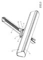
figure 1 shows a perspective view of a single and double joint comprised within one lighting assembly; -
figure 2 shows a side view of the double joint infigure 1 ; -
figure 3 shows a perspective view from below, of a single joint with lighting assembly rotated with respect to a track; -
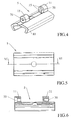
figure 4 shows a perspective view from above, of a first element of a joint according to the invention; -
figure 5 shows a bottom view offigure 4 ; -
figure 6 shows a section view according to the line VI-VI infigure 5 ; -
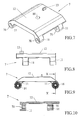
figure 7 shows a perspective view from above, of a second element of a joint with double connection for said first element; -
figure 8 shows a side view offigure 7 ; -
figure 9 shows a back view offigure 7 ; -
figure 10 shows a section view according to the line X-X infigure 9 ; -
figure 11 shows a perspective view from above, of a third element of a joint with single connection for said first element; -
figure 12 shows a top view offigure 11 ; -
figure 13 shows a side view offigure 11 ; -
figure 14 shows a back view offigure 11 ; -
figure 15 shows a section view according to the line XV-XV offigure 12 ; -
figure 16 shows a perspective view from above, of a connection for support track; -
figure 17 shows a perspective view from below, of the connection infigure 16 . - With reference to the accompanying figures, and in particular to
figure 1 , twojoints 1' and 1" are present (whose differences will be explained later) for allowing a tilting/rotating movement of alighting apparatus 2 for elongatedfluorescent lamp 3, of the type obtainable with lamps called T5, with respect to astraight fastening track 4 for thelighting apparatus 2.Track 4 is fixed with respect to a wall/ceiling (not represented). -
Joints 1' and 1" provide a first element 5 (figure 1 ) adapted to integrally hook thelighting apparatus 2 and hinged with at least onehinge 6 to asecond element 7' and 7". - In particular, a first joint 1' provides a first element 5 (
figures 1 ,4-6 ) hinged to a second element 7' having single connection. - Instead, a
second joint 1" provides a pair of hookingelements 5 integral with twolampholders 2 hinged to asingle second element 7" having double connection. Hence, as will be increasingly apparent later, element 7' (figures from 11 to 15) is built to be connected, by means ofhinges 6, to a singlefirst element 5, and hence to asingle lighting apparatus 2, whileelement 7" (figures from 7 to 10) is built to be connected, by means ofhinges 6, to twofirst elements 5, and hence to twolighting apparatuses 2. - The
first element 5 is adapted to allow a tilting movement of thelighting apparatus 2 by means of thehinges 6 with respect to thesecond element 7', 7", and thesecond element 7', 7" is pivotally hinged with a pin 8 (figure 2 ) to aconnection 9 associated withtrack 4.Connection 9 has an engagement profile suitable for being inserted into the respective profile oftrack 4, and here is fixed by the persons skilled in the art. - The axis of the
hinges 6 is perpendicular to the axis of pin 8, which is in turn perpendicular to the axis oftrack 4, and thefirst element 5 has a shaped section 10 (figure 4 ) for a reciprocal engagement with thelighting apparatus 2 and at least oneflange 11 for thehinges 6. Thelighting apparatus 2 may slide horizontally with respect to saidshaped section 10 so as to allow an optimal centring oflamp 3. - The
second element 7', 7" also respectively hasflanges 11 for thehinges 6. - The
flanges 11 of thefirst element 5 and theflanges 11 of thesecond element 7', 7" cooperate by facing each other to form thehinges 6 with pins 60 (for example infigure 1 ), as will become increasingly apparent later. Joint 1' comprises a singlefirst element 5 and one second element 7'. The second element 7' is therefore single, i.e. it only holds one single first element 5 (figure 3 ). - Instead,
joint 1" comprises twofirst elements 5 and one singlesecond element 7". Thesecond element 7" is double, i.e. it holds two first elements 5 (figure 2 ). - The
second element 7', 7" further comprises a flat section 12 (figure 7 ) abutting withconnection 9 to allow stable resting and reciprocal sliding during the rotation between thesecond element 7', 7" andconnection 9 about pin 8. Theflat section 12 in turn has astop 13 to prevent a reciprocal rotation exceeding 360° betweensecond element 7', 7" andconnection 9 about the axis of pin 8. - At least one
flange 11 of thefirst elements 5 has, on thesurface facing flange 11 of thesecond element 7', 7", some projecting elements 15 (figures 4 ,9 ,14 ) which are respectively engaged withgrooves 16 on the facing surface offlange 11 of thesecond element 7', 7" (or vice versa,i.e. projections 15 on thesecond element 7', 7" andgrooves 16 on the first element 5). - For example,
flanges 11 of thesecond element 7', 7" have a plurality ofradial grooves 16 covering the entire contact surface offlange 11 with the respective surface offlange 11 of thefirst element 5, which are equidistant from each other, to define equal sections onflange 11. Thegrooves 16 engage with tworadial projections 15 arranged on the first conformingelement 5 suitable for the temporary engagement withgrooves 16, causingprojections 15 to run free intosuccessive grooves 16. This arrangement is useful during assembly, as will become increasingly apparent later, since it partializes the reciprocal tilting movement betweenfirst element 5 andsecond element 7', 7". - An assembly of
lighting apparatuses 14 is shown infigure 2 and partially shown infigure 1 , comprising onetrack 4, twolighting apparatuses 2 with respectivefluorescent lamps 3 of T5 type and oneconnection 9 according to what described above, comprising adouble joint 7" for thelighting apparatus 2 according to what described above. - In order to obtain the functionalities wanted from the
joints 1', 1" the process is as follows: afirst element 5 is assembled to a second single element 7' or twofirst elements 5 are assembled to a seconddouble element 7", with an assembly which comprises pins 60 (figure 1 ,2 ) in holes 70 (figures 4, 6 ,7, 10 ,11, 15 ) of theflanges 11 of both thefirst elements 5 and thesecond elements 7' and 7", saidholes 70 being aligned to createhinge 6, as shown infigure 1 . - When assembling the
first element 5 to thesecond element 7' or 7", it is possible to control the reciprocal position of thefirst element 5 with respect to thesecond element 7', 7" by rotating theflanges 11 about the axis ofhinge 6 thus taking advantage of the partialization bygrooves 16 and byprojections 15, and by controlling the reciprocal angle with respect to the hinging angle to then fasten it with means known by the person skilled in the art. - A single
first element 5 may be fixed to a second single element 7', or twofirst elements 5 to a seconddouble element 7", also with reciprocal, different inclinations betweenfirst elements 5 andsecond element 7". - The
second element 7', 7" is then hinged by means of pin 8 toconnection 9 by causing theflat section 12 of the second element abutting with theflat section 22 ofconnection 9. Pin 8 engages with through hole 80 (figures 7 ,11, 12, 15 ) of thesecond element 7', 7" and throughhole 90 ofconnection 9, which is aligned withhole 80. - Thereby the
second element 7', 7" rotates about the axis of pin 8 with respect toconnection 9, which is fixed totrack 4 which in turn is fixed to the wall/ceiling. - The reciprocal rotation of the
first element 5 and ofconnection 9 generates a reciprocal rotation between the axis oftrack 4 and thelighting apparatus 2, once it is assembled on thefirst element 5 as seen infigure 3 only if the second element 7' is single. Rotation is fixed with means known by the person skilled in the art. -
First element 5 is coupled with thelighting apparatus 2 by engaging theshaped portion 10 thereof on a respectiveshaped part 100 of the lighting apparatus 2 (figure 1 ) which has a complementary profile. Thus the result is that thelighting apparatus 2 is integral with thefirst element 5. - The
lighting apparatus 2 is thus tilting and rotating in assembly step with respect totrack 4. - The
lighting apparatus 2 may carry a LED lamp instead of a fluorescent lamp, the type ofjoint 1', 1" being the same.
Claims (9)
- A joint (1', 1") for at least one lighting apparatus (2) with elongated lamp (3) which is hookable to a fixed straight track (4) with respect to a wall/ceiling, characterized in that it comprises at least one first element (5) adapted to integrally hook one lighting apparatus (2) and connected by means of hinges (6) to a second element (7', 7") pivotally hinged with a pin (8) to a connection (9) associated with said track (4).
- A joint (1', 1") according to claim 1, characterized in that the axis of the hinges (6) is perpendicular to the axis of the pin (8) which is in turn perpendicular to the axis of the track (4).
- A joint (1', 1") according to claim 2, characterized in that the lighting apparatus (2) is slidingly associated with a shaped section (10) of the first element (5) which also provides at least one flange (11) for the hinges (6).
- A joint (1', 1") according to claim 3, characterized in that the second element (7', 7") has at least one flange (11) for the hinges (6).
- A joint (1', 1") according to claim 4, characterized in that the second element (7', 7") has a flat section (12) abutting with the connection (9) to allow stable resting and reciprocal sliding during the rotation between second element (7', 7") and connection (9).
- A joint (1') according to any one of the preceding claims, characterized in that the second element (7') has flanges (11) for the association with one single first element (5).
- A joint (1") according to any one of the preceding claims from 1 to 5, characterized in that the second element (7") has flanges (11) for the association with two first elements (5).
- A joint (1', 1") according to any one of the preceding claims, characterized in that one flange (11) of the first element (5) has, on the surface facing the flange (11) of the second element (7', 7"), a number of projecting elements (15) or grooves (16) which are respectively engaged with grooves (16) or projecting elements (15) on the facing surface of flange (11) of the second element (7', 7").
- A joint (1', 1") according to any one of the preceding claims, characterized in that it is for fluorescent lamps, preferably of T5 type, or for LED lamps.
Applications Claiming Priority (1)
| Application Number | Priority Date | Filing Date | Title |
|---|---|---|---|
| IT000260U ITMI20100260U1 (en) | 2010-07-29 | 2010-07-29 | JOINT FOR EQUIPMENT D ILLUMINATED SHAPE LIGHTS. |
Publications (2)
| Publication Number | Publication Date |
|---|---|
| EP2413028A2 true EP2413028A2 (en) | 2012-02-01 |
| EP2413028A3 EP2413028A3 (en) | 2013-11-20 |
Family
ID=43740167
Family Applications (1)
| Application Number | Title | Priority Date | Filing Date |
|---|---|---|---|
| EP11161760.1A Withdrawn EP2413028A3 (en) | 2010-07-29 | 2011-04-08 | Joint for elongated lighting apparatus |
Country Status (2)
| Country | Link |
|---|---|
| EP (1) | EP2413028A3 (en) |
| IT (1) | ITMI20100260U1 (en) |
Cited By (14)
| Publication number | Priority date | Publication date | Assignee | Title |
|---|---|---|---|---|
| EP2813753A1 (en) * | 2013-06-11 | 2014-12-17 | Ruco-Licht GmbH | Lamp |
| EP2821695A1 (en) * | 2013-07-01 | 2015-01-07 | Flowmagic Holding B.V. | Assembly of voltage rail, adapter and led-tube, adapter suitable for the assembly and method of mounting lighting elements |
| CN104696783A (en) * | 2013-12-06 | 2015-06-10 | 广东凯西欧照明有限公司 | Guide rail lamp liable to be replaced and installed |
| CN104696912A (en) * | 2013-12-06 | 2015-06-10 | 广东凯西欧照明有限公司 | Track lamp convenient to mount and replace |
| CN104696910A (en) * | 2013-12-06 | 2015-06-10 | 广东凯西欧照明有限公司 | Guide rail lamp convenient for installation and replacement |
| CN104696788A (en) * | 2013-12-06 | 2015-06-10 | 广东凯西欧照明有限公司 | Guide rail lamp convenient for replacement and installation |
| CN104696790A (en) * | 2013-12-06 | 2015-06-10 | 广东凯西欧照明有限公司 | Guide rail lamp convenient for installation and replacement |
| CN104696909A (en) * | 2013-12-06 | 2015-06-10 | 广东凯西欧照明有限公司 | Guide rail lamp convenient to mount |
| CN104696802A (en) * | 2013-12-06 | 2015-06-10 | 广东凯西欧照明有限公司 | Guide rail lamp liable to be installed and replaced |
| CN104696797A (en) * | 2013-12-06 | 2015-06-10 | 广东凯西欧照明有限公司 | Track lamp convenient to mount |
| US20170082270A1 (en) * | 2014-07-01 | 2017-03-23 | Fluence Bioengineering | Systems and methods for a dynamic light fixture |
| WO2019081131A1 (en) * | 2017-10-26 | 2019-05-02 | Zumtobel Lighting Gmbh | MOUNTING UNIT FOR MOUNTING A LIGHT ON A TRACKING ELEMENT |
| WO2023143998A1 (en) * | 2022-01-27 | 2023-08-03 | Signify Holding B.V. | Track lighting system |
| DE102023132212B3 (en) | 2023-11-20 | 2025-01-16 | Rzb Rudolf Zimmermann, Bamberg Gmbh | Multi-part housing body |
Family Cites Families (2)
| Publication number | Priority date | Publication date | Assignee | Title |
|---|---|---|---|---|
| US5655833A (en) * | 1995-06-07 | 1997-08-12 | Control Alt Design Ltd. | Free-standing task lighting fixture |
| US5593224A (en) * | 1995-09-22 | 1997-01-14 | Thomas Industries | Field-adjustable internal pivot tension device |
-
2010
- 2010-07-29 IT IT000260U patent/ITMI20100260U1/en unknown
-
2011
- 2011-04-08 EP EP11161760.1A patent/EP2413028A3/en not_active Withdrawn
Non-Patent Citations (1)
| Title |
|---|
| None |
Cited By (21)
| Publication number | Priority date | Publication date | Assignee | Title |
|---|---|---|---|---|
| EP2813753A1 (en) * | 2013-06-11 | 2014-12-17 | Ruco-Licht GmbH | Lamp |
| EP2821695A1 (en) * | 2013-07-01 | 2015-01-07 | Flowmagic Holding B.V. | Assembly of voltage rail, adapter and led-tube, adapter suitable for the assembly and method of mounting lighting elements |
| CN104696797B (en) * | 2013-12-06 | 2017-01-18 | 广东凯西欧照明有限公司 | Track lamp convenient to mount |
| CN104696790B (en) * | 2013-12-06 | 2017-01-25 | 广东凯西欧照明有限公司 | Guide rail lamp convenient for installation and replacement |
| CN104696910A (en) * | 2013-12-06 | 2015-06-10 | 广东凯西欧照明有限公司 | Guide rail lamp convenient for installation and replacement |
| CN104696788A (en) * | 2013-12-06 | 2015-06-10 | 广东凯西欧照明有限公司 | Guide rail lamp convenient for replacement and installation |
| CN104696790A (en) * | 2013-12-06 | 2015-06-10 | 广东凯西欧照明有限公司 | Guide rail lamp convenient for installation and replacement |
| CN104696909A (en) * | 2013-12-06 | 2015-06-10 | 广东凯西欧照明有限公司 | Guide rail lamp convenient to mount |
| CN104696802A (en) * | 2013-12-06 | 2015-06-10 | 广东凯西欧照明有限公司 | Guide rail lamp liable to be installed and replaced |
| CN104696797A (en) * | 2013-12-06 | 2015-06-10 | 广东凯西欧照明有限公司 | Track lamp convenient to mount |
| CN104696783A (en) * | 2013-12-06 | 2015-06-10 | 广东凯西欧照明有限公司 | Guide rail lamp liable to be replaced and installed |
| CN104696912A (en) * | 2013-12-06 | 2015-06-10 | 广东凯西欧照明有限公司 | Track lamp convenient to mount and replace |
| CN104696783B (en) * | 2013-12-06 | 2017-02-01 | 广东凯西欧照明有限公司 | Guide rail lamp liable to be replaced and installed |
| CN104696788B (en) * | 2013-12-06 | 2017-02-15 | 广东凯西欧照明有限公司 | Guide rail lamp convenient for replacement and installation |
| US20170082270A1 (en) * | 2014-07-01 | 2017-03-23 | Fluence Bioengineering | Systems and methods for a dynamic light fixture |
| WO2019081131A1 (en) * | 2017-10-26 | 2019-05-02 | Zumtobel Lighting Gmbh | MOUNTING UNIT FOR MOUNTING A LIGHT ON A TRACKING ELEMENT |
| CN111279126A (en) * | 2017-10-26 | 2020-06-12 | 宗拓贝尔照明器材有限公司 | Fastening unit for fixing the lamp to the support |
| CN111279126B (en) * | 2017-10-26 | 2022-05-27 | 宗拓贝尔照明器材有限公司 | Fastening unit for fixing the lamp to the support |
| WO2023143998A1 (en) * | 2022-01-27 | 2023-08-03 | Signify Holding B.V. | Track lighting system |
| US12345396B2 (en) | 2022-01-27 | 2025-07-01 | Signify Holding B.V. | Track lighting system |
| DE102023132212B3 (en) | 2023-11-20 | 2025-01-16 | Rzb Rudolf Zimmermann, Bamberg Gmbh | Multi-part housing body |
Also Published As
| Publication number | Publication date |
|---|---|
| ITMI20100260U1 (en) | 2012-01-30 |
| EP2413028A3 (en) | 2013-11-20 |
Similar Documents
| Publication | Publication Date | Title |
|---|---|---|
| US9696021B2 (en) | Hanger bar for recessed luminaires | |
| US8042977B1 (en) | Troffer luminaire | |
| US8240630B2 (en) | Hanger bar for recessed luminaires with integral nail | |
| ITMI20100260U1 (en) | JOINT FOR EQUIPMENT D ILLUMINATED SHAPE LIGHTS. | |
| US10247389B2 (en) | Light fixture assembly with pivoting reflector assembly and lens assembly | |
| US7055982B2 (en) | Linear fixture assembly | |
| US20110317435A1 (en) | Lighting system | |
| US6220721B1 (en) | Multi-lyte channel lighting system | |
| EP3067616B1 (en) | Recessed track lighting fixture | |
| US20240125121A1 (en) | Panel mounting system | |
| US20090213621A1 (en) | Luminaire profile | |
| KR200491881Y1 (en) | Sliding adapter for intuitive rail lights | |
| USRE50516E1 (en) | Lighting system for suspended ceiling | |
| US20210254815A1 (en) | Removable positioning of light fixtures | |
| US20180051854A1 (en) | Retrofit kit and methods for conversion of fluorescent light assemblies to led assemblies | |
| KR20130063142A (en) | Led line bar attachment device | |
| US10941569B2 (en) | Clip hanger and ceiling suspension system incorporating same | |
| KR200261004Y1 (en) | A type of fluorescent light for suspend on ceiling with fit structure | |
| US20080112172A1 (en) | Adjustment clip for a suspended light fixture | |
| US20260055862A1 (en) | Modular track lighting system | |
| CN203969701U (en) | A kind of cupboard | |
| US11867384B2 (en) | Removable positioning of light fixtures | |
| KR200448128Y1 (en) | Socket holder for downlights with adjustable rotation and angle | |
| KR20180094264A (en) | Module Bar and Ceiling Finish Installation Structure using such Module Bar | |
| KR20170103591A (en) | Lighting box installation equipment of ceiling |
Legal Events
| Date | Code | Title | Description |
|---|---|---|---|
| AK | Designated contracting states |
Kind code of ref document: A2 Designated state(s): AL AT BE BG CH CY CZ DE DK EE ES FI FR GB GR HR HU IE IS IT LI LT LU LV MC MK MT NL NO PL PT RO RS SE SI SK SM TR |
|
| AX | Request for extension of the european patent |
Extension state: BA ME |
|
| PUAI | Public reference made under article 153(3) epc to a published international application that has entered the european phase |
Free format text: ORIGINAL CODE: 0009012 |
|
| PUAL | Search report despatched |
Free format text: ORIGINAL CODE: 0009013 |
|
| AK | Designated contracting states |
Kind code of ref document: A3 Designated state(s): AL AT BE BG CH CY CZ DE DK EE ES FI FR GB GR HR HU IE IS IT LI LT LU LV MC MK MT NL NO PL PT RO RS SE SI SK SM TR |
|
| AX | Request for extension of the european patent |
Extension state: BA ME |
|
| RIC1 | Information provided on ipc code assigned before grant |
Ipc: F21Y 103/00 20060101ALN20131017BHEP Ipc: F21V 21/28 20060101AFI20131017BHEP Ipc: F21V 21/30 20060101ALI20131017BHEP Ipc: F21V 21/34 20060101ALI20131017BHEP |
|
| 17P | Request for examination filed |
Effective date: 20140519 |
|
| RBV | Designated contracting states (corrected) |
Designated state(s): AL AT BE BG CH CY CZ DE DK EE ES FI FR GB GR HR HU IE IS IT LI LT LU LV MC MK MT NL NO PL PT RO RS SE SI SK SM TR |
|
| RIC1 | Information provided on ipc code assigned before grant |
Ipc: F21Y 103/00 20060101ALN20181030BHEP Ipc: F21V 21/28 20060101AFI20181030BHEP Ipc: F21V 21/30 20060101ALI20181030BHEP Ipc: F21V 21/34 20060101ALI20181030BHEP |
|
| GRAP | Despatch of communication of intention to grant a patent |
Free format text: ORIGINAL CODE: EPIDOSNIGR1 |
|
| INTG | Intention to grant announced |
Effective date: 20181213 |
|
| STAA | Information on the status of an ep patent application or granted ep patent |
Free format text: STATUS: THE APPLICATION IS DEEMED TO BE WITHDRAWN |
|
| 18D | Application deemed to be withdrawn |
Effective date: 20190424 |