EP2412953A2 - Inorganic coke resistant coatings to prevent aircraft fuel system fouling - Google Patents
Inorganic coke resistant coatings to prevent aircraft fuel system fouling Download PDFInfo
- Publication number
- EP2412953A2 EP2412953A2 EP20110172127 EP11172127A EP2412953A2 EP 2412953 A2 EP2412953 A2 EP 2412953A2 EP 20110172127 EP20110172127 EP 20110172127 EP 11172127 A EP11172127 A EP 11172127A EP 2412953 A2 EP2412953 A2 EP 2412953A2
- Authority
- EP
- European Patent Office
- Prior art keywords
- fuel
- coating
- fuel system
- hot section
- titanium
- Prior art date
- Legal status (The legal status is an assumption and is not a legal conclusion. Google has not performed a legal analysis and makes no representation as to the accuracy of the status listed.)
- Withdrawn
Links
- 239000000446 fuel Substances 0.000 title claims abstract description 105
- 238000000576 coating method Methods 0.000 title claims description 44
- 239000000571 coke Substances 0.000 title description 2
- 238000005524 ceramic coating Methods 0.000 claims abstract description 12
- 238000004939 coking Methods 0.000 claims abstract description 11
- 239000002828 fuel tank Substances 0.000 claims abstract description 8
- 239000000203 mixture Substances 0.000 claims abstract description 6
- 238000002485 combustion reaction Methods 0.000 claims abstract description 5
- 238000004891 communication Methods 0.000 claims abstract description 5
- 239000012530 fluid Substances 0.000 claims abstract description 5
- 150000001247 metal acetylides Chemical class 0.000 claims abstract description 5
- 150000004767 nitrides Chemical class 0.000 claims abstract description 5
- 229910021332 silicide Inorganic materials 0.000 claims abstract description 5
- 239000011248 coating agent Substances 0.000 claims description 28
- 238000000034 method Methods 0.000 claims description 10
- UQZIWOQVLUASCR-UHFFFAOYSA-N alumane;titanium Chemical compound [AlH3].[Ti] UQZIWOQVLUASCR-UHFFFAOYSA-N 0.000 claims description 8
- 229910052580 B4C Inorganic materials 0.000 claims description 6
- NRTOMJZYCJJWKI-UHFFFAOYSA-N Titanium nitride Chemical compound [Ti]#N NRTOMJZYCJJWKI-UHFFFAOYSA-N 0.000 claims description 6
- SJKRCWUQJZIWQB-UHFFFAOYSA-N azane;chromium Chemical compound N.[Cr] SJKRCWUQJZIWQB-UHFFFAOYSA-N 0.000 claims description 6
- INAHAJYZKVIDIZ-UHFFFAOYSA-N boron carbide Chemical compound B12B3B4C32B41 INAHAJYZKVIDIZ-UHFFFAOYSA-N 0.000 claims description 6
- 229910052582 BN Inorganic materials 0.000 claims description 5
- PZNSFCLAULLKQX-UHFFFAOYSA-N Boron nitride Chemical compound N#B PZNSFCLAULLKQX-UHFFFAOYSA-N 0.000 claims description 5
- RTAQQCXQSZGOHL-UHFFFAOYSA-N Titanium Chemical compound [Ti] RTAQQCXQSZGOHL-UHFFFAOYSA-N 0.000 claims description 4
- 239000010936 titanium Substances 0.000 claims description 4
- 229910052719 titanium Inorganic materials 0.000 claims description 4
- -1 titanium aluminum silicon Chemical compound 0.000 claims description 4
- MTPVUVINMAGMJL-UHFFFAOYSA-N trimethyl(1,1,2,2,2-pentafluoroethyl)silane Chemical compound C[Si](C)(C)C(F)(F)C(F)(F)F MTPVUVINMAGMJL-UHFFFAOYSA-N 0.000 claims description 4
- 238000007740 vapor deposition Methods 0.000 claims description 4
- 239000003921 oil Substances 0.000 claims description 3
- 230000004888 barrier function Effects 0.000 claims description 2
- 150000001875 compounds Chemical class 0.000 claims 8
- 239000004215 Carbon black (E152) Substances 0.000 description 5
- 229930195733 hydrocarbon Natural products 0.000 description 5
- 150000002430 hydrocarbons Chemical class 0.000 description 5
- 238000004519 manufacturing process Methods 0.000 description 5
- CXOWYMLTGOFURZ-UHFFFAOYSA-N azanylidynechromium Chemical compound [Cr]#N CXOWYMLTGOFURZ-UHFFFAOYSA-N 0.000 description 4
- 239000003575 carbonaceous material Substances 0.000 description 4
- 230000007257 malfunction Effects 0.000 description 4
- 238000006243 chemical reaction Methods 0.000 description 3
- 239000000463 material Substances 0.000 description 3
- 239000000126 substance Substances 0.000 description 3
- 230000015572 biosynthetic process Effects 0.000 description 2
- 229910010293 ceramic material Inorganic materials 0.000 description 2
- 238000010586 diagram Methods 0.000 description 2
- 239000007769 metal material Substances 0.000 description 2
- 230000003746 surface roughness Effects 0.000 description 2
- RYGMFSIKBFXOCR-UHFFFAOYSA-N Copper Chemical compound [Cu] RYGMFSIKBFXOCR-UHFFFAOYSA-N 0.000 description 1
- 229920006362 Teflon® Polymers 0.000 description 1
- 238000009825 accumulation Methods 0.000 description 1
- 230000003373 anti-fouling effect Effects 0.000 description 1
- 239000010949 copper Substances 0.000 description 1
- 229910052802 copper Inorganic materials 0.000 description 1
- 230000003247 decreasing effect Effects 0.000 description 1
- 230000008021 deposition Effects 0.000 description 1
- 229910003460 diamond Inorganic materials 0.000 description 1
- 239000010432 diamond Substances 0.000 description 1
- 230000000694 effects Effects 0.000 description 1
- 238000009472 formulation Methods 0.000 description 1
- 230000005764 inhibitory process Effects 0.000 description 1
- 239000007788 liquid Substances 0.000 description 1
- 230000003137 locomotive effect Effects 0.000 description 1
- 238000012423 maintenance Methods 0.000 description 1
- 238000012986 modification Methods 0.000 description 1
- 230000004048 modification Effects 0.000 description 1
- 230000002265 prevention Effects 0.000 description 1
Images


Classifications
-
- F—MECHANICAL ENGINEERING; LIGHTING; HEATING; WEAPONS; BLASTING
- F02—COMBUSTION ENGINES; HOT-GAS OR COMBUSTION-PRODUCT ENGINE PLANTS
- F02C—GAS-TURBINE PLANTS; AIR INTAKES FOR JET-PROPULSION PLANTS; CONTROLLING FUEL SUPPLY IN AIR-BREATHING JET-PROPULSION PLANTS
- F02C7/00—Features, components parts, details or accessories, not provided for in, or of interest apart form groups F02C1/00 - F02C6/00; Air intakes for jet-propulsion plants
- F02C7/22—Fuel supply systems
- F02C7/222—Fuel flow conduits, e.g. manifolds
-
- F—MECHANICAL ENGINEERING; LIGHTING; HEATING; WEAPONS; BLASTING
- F05—INDEXING SCHEMES RELATING TO ENGINES OR PUMPS IN VARIOUS SUBCLASSES OF CLASSES F01-F04
- F05D—INDEXING SCHEME FOR ASPECTS RELATING TO NON-POSITIVE-DISPLACEMENT MACHINES OR ENGINES, GAS-TURBINES OR JET-PROPULSION PLANTS
- F05D2230/00—Manufacture
- F05D2230/30—Manufacture with deposition of material
- F05D2230/31—Layer deposition
- F05D2230/313—Layer deposition by physical vapour deposition
-
- F—MECHANICAL ENGINEERING; LIGHTING; HEATING; WEAPONS; BLASTING
- F05—INDEXING SCHEMES RELATING TO ENGINES OR PUMPS IN VARIOUS SUBCLASSES OF CLASSES F01-F04
- F05D—INDEXING SCHEME FOR ASPECTS RELATING TO NON-POSITIVE-DISPLACEMENT MACHINES OR ENGINES, GAS-TURBINES OR JET-PROPULSION PLANTS
- F05D2230/00—Manufacture
- F05D2230/30—Manufacture with deposition of material
- F05D2230/31—Layer deposition
- F05D2230/314—Layer deposition by chemical vapour deposition
-
- F—MECHANICAL ENGINEERING; LIGHTING; HEATING; WEAPONS; BLASTING
- F05—INDEXING SCHEMES RELATING TO ENGINES OR PUMPS IN VARIOUS SUBCLASSES OF CLASSES F01-F04
- F05D—INDEXING SCHEME FOR ASPECTS RELATING TO NON-POSITIVE-DISPLACEMENT MACHINES OR ENGINES, GAS-TURBINES OR JET-PROPULSION PLANTS
- F05D2230/00—Manufacture
- F05D2230/90—Coating; Surface treatment
-
- F—MECHANICAL ENGINEERING; LIGHTING; HEATING; WEAPONS; BLASTING
- F05—INDEXING SCHEMES RELATING TO ENGINES OR PUMPS IN VARIOUS SUBCLASSES OF CLASSES F01-F04
- F05D—INDEXING SCHEME FOR ASPECTS RELATING TO NON-POSITIVE-DISPLACEMENT MACHINES OR ENGINES, GAS-TURBINES OR JET-PROPULSION PLANTS
- F05D2300/00—Materials; Properties thereof
- F05D2300/20—Oxide or non-oxide ceramics
-
- F—MECHANICAL ENGINEERING; LIGHTING; HEATING; WEAPONS; BLASTING
- F05—INDEXING SCHEMES RELATING TO ENGINES OR PUMPS IN VARIOUS SUBCLASSES OF CLASSES F01-F04
- F05D—INDEXING SCHEME FOR ASPECTS RELATING TO NON-POSITIVE-DISPLACEMENT MACHINES OR ENGINES, GAS-TURBINES OR JET-PROPULSION PLANTS
- F05D2300/00—Materials; Properties thereof
- F05D2300/20—Oxide or non-oxide ceramics
- F05D2300/22—Non-oxide ceramics
-
- F—MECHANICAL ENGINEERING; LIGHTING; HEATING; WEAPONS; BLASTING
- F05—INDEXING SCHEMES RELATING TO ENGINES OR PUMPS IN VARIOUS SUBCLASSES OF CLASSES F01-F04
- F05D—INDEXING SCHEME FOR ASPECTS RELATING TO NON-POSITIVE-DISPLACEMENT MACHINES OR ENGINES, GAS-TURBINES OR JET-PROPULSION PLANTS
- F05D2300/00—Materials; Properties thereof
- F05D2300/20—Oxide or non-oxide ceramics
- F05D2300/22—Non-oxide ceramics
- F05D2300/226—Carbides
-
- F—MECHANICAL ENGINEERING; LIGHTING; HEATING; WEAPONS; BLASTING
- F05—INDEXING SCHEMES RELATING TO ENGINES OR PUMPS IN VARIOUS SUBCLASSES OF CLASSES F01-F04
- F05D—INDEXING SCHEME FOR ASPECTS RELATING TO NON-POSITIVE-DISPLACEMENT MACHINES OR ENGINES, GAS-TURBINES OR JET-PROPULSION PLANTS
- F05D2300/00—Materials; Properties thereof
- F05D2300/20—Oxide or non-oxide ceramics
- F05D2300/22—Non-oxide ceramics
- F05D2300/228—Nitrides
-
- F—MECHANICAL ENGINEERING; LIGHTING; HEATING; WEAPONS; BLASTING
- F05—INDEXING SCHEMES RELATING TO ENGINES OR PUMPS IN VARIOUS SUBCLASSES OF CLASSES F01-F04
- F05D—INDEXING SCHEME FOR ASPECTS RELATING TO NON-POSITIVE-DISPLACEMENT MACHINES OR ENGINES, GAS-TURBINES OR JET-PROPULSION PLANTS
- F05D2300/00—Materials; Properties thereof
- F05D2300/60—Properties or characteristics given to material by treatment or manufacturing
- F05D2300/611—Coating
-
- Y—GENERAL TAGGING OF NEW TECHNOLOGICAL DEVELOPMENTS; GENERAL TAGGING OF CROSS-SECTIONAL TECHNOLOGIES SPANNING OVER SEVERAL SECTIONS OF THE IPC; TECHNICAL SUBJECTS COVERED BY FORMER USPC CROSS-REFERENCE ART COLLECTIONS [XRACs] AND DIGESTS
- Y10—TECHNICAL SUBJECTS COVERED BY FORMER USPC
- Y10T—TECHNICAL SUBJECTS COVERED BY FORMER US CLASSIFICATION
- Y10T137/00—Fluid handling
- Y10T137/8593—Systems
Definitions
- the present invention relates to fuel systems and associated methods of manufacture, and more particularly to those suitable for use with gas turbine engines.
- Gas turbine engines such as those suitable for use with aircraft, generally use hydrocarbon-based fuels.
- Coking is often catalyzed by surfaces of fuel system components wetted by hydrocarbon-based fuel, and some materials (e.g., copper) are more likely than others to catalyze coking.
- carbonaceous materials can undesirably accumulate on fuel system components such as conduits, valve surfaces, filter screens, etc., and can lead to malfunctions, decreased fuel flow, binding system components and/or increased needs for repair or maintenance.
- a fuel system for delivering fuel to an engine includes a fuel tank, a hot section in fluid communication with the fuel tank for delivering fuel for combustion by the engine, and a coating applied to at least a portion of the hot section for reducing fuel coking.
- the coatings include ceramic materials such as carbides, nitrides, carbonitrides and silicides. Examples are boron carbide, titanium nitride, chromium nitride, titanium aluminum carbonitride, titanium aluminum silicon carbonitride, titanium carbide, titanium aluminum nitride, titanium carbonitride, chromium nitride and boron nitride.
- the coating may be applied by vapor deposition or other methods on discrete pieces of the fuel system prior to assembly.
- the coatings exhibit excellent adhesion to common fuel system surfaces. Since the coatings are thin, care should be taken to have smooth surfaces where the coatings are applied. Smoothness should be no more than 16 micro-inches (0.0004 mm) Surface Roughness RA and as low as 4 micro-inches (0.0001 mm) Surface Roughness RA.
- the coatings have a low coefficient of friction and mold release characteristics creating surfaces that diminish the adhesion of foreign substances.
- FIG. 1 is a block diagram of an aircraft having a fuel system according to the present invention.
- FIG. 2 is a cross-sectional view of a coated component of the fuel system.
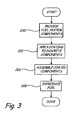
- FIG. 3 is a flow chart of a method of making the fuel system according to the present invention.
- the present invention provides a system and associated method of making a fuel system at least partially coated to reduce coking and fouling.
- the coating comprises a ceramic material that is deposited on the surface to be coated, such as boron carbide, titanium nitride, chromium nitride and boron nitride.
- the coatings reduce the formation and deposition of carbonaceous material in the fuel system, and can help enable elevated fuel system operating temperatures (e.g., at least approximately 135° C (275° F)).
- elevated fuel system operating temperatures e.g., at least approximately 135° C (275° F)
- the inhibition of undesirable chemical reactions and prevention of deposit adhesion provides a cleaner fuel system with less system fouling, fewer resulting malfunctions, and longer service intervals.
- the coating may be uniformly applied by vapor deposition (chemical or physical) on discrete pieces of the fuel system prior to assembly.
- discrete fuel system components are coated and then assembled together in the fuel system.
- the coatings of this invention are applied in a very thin layer.
- An example range of coating thickness is from about 1 micron to about 10 microns, with a further example range being about 1 micron to about 5 microns.
- This thin coating enables use of parts requiring very tight tolerances.
- the surfaces being coated should be smooth and not have imperfections or other matter that would interfere with the formation of these thin coatings.
- These ceramic coatings are very hard and possess a high durability relative to organic style coatings.
- FIG. 1 is a block diagram of an aircraft 10 that includes a gas turbine engine 12 and a fuel system 14.
- the gas turbine engine 12 includes a combustor 16 that accepts fuel delivered by the fuel system 14 for combustion, in order to power the aircraft 10.
- the aircraft 10 and the gas turbine engine 12 can include additional components not specifically shown.
- the fuel system 14 includes a fuel tank 18, a heat exchanger 20, one or more valves 22, one or more filters 24, and suitable conduits 26.
- the fuel tank 18 is carried on the aircraft 10, and can store a suitable hydrocarbon-based fuel for the gas turbine engine 12, such as known fuel formulations like Jet A and Jet A-1 (defined by industry specification ASTM D 1655) or JP-8 (defined by military specification MIL-DTL-83133).
- the heat exchanger 20 e.g., a fuel/oil heat exchanger
- the valves 22, the filters 24, and the conduits 26 are fluidically connected between the heat exchanger 20 and the combustor 16, in any suitable arrangement.
- the fuel system 14 illustrated in FIG. 1 is provided merely by way of example and not limitation.
- the fuel system 14 can include additional components not shown, such as a fuel pump and a fuel metering unit (FMU), and can have other configurations and arrangements as desired for particular applications.
- FMU fuel metering unit
- Fuel in the hot section 28 is generally at an elevated operating temperature, that is, it is at a temperature generally greater than room temperature or ambient temperature. In one embodiment, fuel in the hot section 28 has an operating temperature of at least approximately 135° C (275° F). In other embodiments, the fuel can have higher or lower operating temperatures.
- Portions of the fuel system 14 have a coating on selected surfaces exposed to fuel, which helps reduce a risk of coking by being relatively catalytically inactive with respect to typical hydrocarbon-based gas turbine engine fuels and also by reducing the ability of carbonaceous materials present in fuel from adhering to surfaces within the fuel system 14.
- the ceramic coating is generally fuel resistant, anti-fouling, thin, has relatively good adhesion properties, is thermally stable at or above elevated gas turbine engine fuel system operating temperatures, and is durable.
- FIG. 2 is a cross-sectional view of one of the conduits 26 of the fuel system 14 having a coating 30.
- a liquid, hydrocarbon-based fuel 32 is present within the conduit 26, which can be made of a metallic material.
- the coating 30 is located along interior surfaces of the conduit 26, and forms essentially a barrier between the fuel 32 and the metallic material of the conduit 26. It should be noted that FIG. 2 is not necessarily shown to scale.
- Coating 30 comprises a ceramic coating such as carbides, nitrides, carbonitrides and silicides. Examples are boron carbide, titanium nitride, chromium nitride, titanium aluminum carbonitride, titanium aluminum silicon carbonitride, titanium carbide, titanium aluminum nitride, titanium carbonitride, chromium nitride and boron nitride. Coating 30 has a thickness of from about 1 micron to about 10 microns and may be limited from about 1 micron to about 5 microns, as noted above. These coatings 30 exhibit excellent adhesion to common fuel system surfaces 26 that are smooth and do not contain imperfections.
- Coatings 30 will inhibit the adhesion of carbonaceous deposits of the fuel wetted surfaces of the fuel system 14. In addition, coatings 30 will insulate the fuel from the metallic surfaces of the fuel system 14 that might otherwise catalyze the chemical reactions that generate the coke.
- Examples of commercially available coatings are Diamond Black boron carbide, Ion Bond 7-22 titanium nitride and Ion bond 7-24 chromium nitride. These coatings have thermal capability well in excess of 275° F (135° C) and use in an aircraft fuel system would allow the aircraft to operate at fuel system temperatures that would otherwise generate an unacceptable level of carbonaceous deposits and foul the fuel system.
- FIG. 3 is a flow chart of a method of making the fuel system 14.
- components of the fuel system 14 are provided in at least partially unassembled state (step 200).
- the fuel system 14 is not fully assembled, but rather discrete components of the fuel system 14 are available essentially individually, though it is possible for some components to be assembled together (e.g., certain parts can be connected together).
- the coating 30 is applied to the discrete components of the fuel system 14 (step 202).
- Coating application at step 202 can be accomplished through vapor deposition (chemical or physical).
- the coating 30 can be applied to components of the fuel system 14 individually, or to a group of components essentially simultaneously.
- the coated components are assembled together to define the completed fuel system 14 (step 206), and the fuel 32 can be introduced to the fuel system 14 (step 208). Operation of the fuel system 14, the gas turbine engine 12 and the aircraft 10 can then begin. It should be noted that the method of making the fuel system 14 described with respect to FIG. 3 can optionally include additional steps not specifically mentioned.
- the present invention provides numerous technical effects.
- the present invention can help aircraft fuel systems achieve operating temperatures of at least approximately 135° C (275° F) while also helping to provide extended operating hour overhaul limits.
- a coated fuel system according to the present invention can help reduce undesirable coking, and can help permit fuel system operating temperatures that would otherwise generate an unacceptable level of carbonaceous deposits and fouling of the fuel system.
- use of a ceramic coating according to the present invention helps reduce any accumulation of carbonaceous materials on fuel system components, and allows for much thinner coating thicknesses than with other materials such as Teflon® brand coatings.
- the present invention can help enable the use of relatively small and light heat exchangers.
Landscapes
- Engineering & Computer Science (AREA)
- Chemical & Material Sciences (AREA)
- Combustion & Propulsion (AREA)
- Mechanical Engineering (AREA)
- General Engineering & Computer Science (AREA)
- Other Surface Treatments For Metallic Materials (AREA)
- Paints Or Removers (AREA)
Abstract
Description
- The present invention relates to fuel systems and associated methods of manufacture, and more particularly to those suitable for use with gas turbine engines.
- Gas turbine engines, such as those suitable for use with aircraft, generally use hydrocarbon-based fuels. The elevated temperatures at which prior art gas turbine engine fuel systems operate-up to approximately 121° C (250° F)-can cause chemical reactions to occur referred to in the art as fuel "coking". Coking is often catalyzed by surfaces of fuel system components wetted by hydrocarbon-based fuel, and some materials (e.g., copper) are more likely than others to catalyze coking. Once formed, carbonaceous materials can undesirably accumulate on fuel system components such as conduits, valve surfaces, filter screens, etc., and can lead to malfunctions, decreased fuel flow, binding system components and/or increased needs for repair or maintenance.
- These kinds of malfunctions have been observed in fuel systems that operate at a fuel temperature of approximately 250° F (121° C). As systems are developed and improved, it is expected that they will operate at a fuel temperature of approximately 275° F (135° C), which poses additional risks of system malfunctions due to fuel coking.
- A fuel system for delivering fuel to an engine according to the present invention includes a fuel tank, a hot section in fluid communication with the fuel tank for delivering fuel for combustion by the engine, and a coating applied to at least a portion of the hot section for reducing fuel coking. The coatings include ceramic materials such as carbides, nitrides, carbonitrides and silicides. Examples are boron carbide, titanium nitride, chromium nitride, titanium aluminum carbonitride, titanium aluminum silicon carbonitride, titanium carbide, titanium aluminum nitride, titanium carbonitride, chromium nitride and boron nitride.
- The coating may be applied by vapor deposition or other methods on discrete pieces of the fuel system prior to assembly. The coatings exhibit excellent adhesion to common fuel system surfaces. Since the coatings are thin, care should be taken to have smooth surfaces where the coatings are applied. Smoothness should be no more than 16 micro-inches (0.0004 mm) Surface Roughness RA and as low as 4 micro-inches (0.0001 mm) Surface Roughness RA. The coatings have a low coefficient of friction and mold release characteristics creating surfaces that diminish the adhesion of foreign substances.
-
FIG. 1 is a block diagram of an aircraft having a fuel system according to the present invention. -
FIG. 2 is a cross-sectional view of a coated component of the fuel system. -
FIG. 3 is a flow chart of a method of making the fuel system according to the present invention. - In general, the present invention provides a system and associated method of making a fuel system at least partially coated to reduce coking and fouling. In one embodiment, the coating comprises a ceramic material that is deposited on the surface to be coated, such as boron carbide, titanium nitride, chromium nitride and boron nitride. The coatings reduce the formation and deposition of carbonaceous material in the fuel system, and can help enable elevated fuel system operating temperatures (e.g., at least approximately 135° C (275° F)). The inhibition of undesirable chemical reactions and prevention of deposit adhesion provides a cleaner fuel system with less system fouling, fewer resulting malfunctions, and longer service intervals.
- The coating may be uniformly applied by vapor deposition (chemical or physical) on discrete pieces of the fuel system prior to assembly. In an exemplary embodiment, discrete fuel system components are coated and then assembled together in the fuel system.
- The coatings of this invention are applied in a very thin layer. An example range of coating thickness is from about 1 micron to about 10 microns, with a further example range being about 1 micron to about 5 microns. This thin coating enables use of parts requiring very tight tolerances. As noted above, the surfaces being coated should be smooth and not have imperfections or other matter that would interfere with the formation of these thin coatings. These ceramic coatings are very hard and possess a high durability relative to organic style coatings.
-
FIG. 1 is a block diagram of anaircraft 10 that includes agas turbine engine 12 and afuel system 14. Thegas turbine engine 12 includes acombustor 16 that accepts fuel delivered by thefuel system 14 for combustion, in order to power theaircraft 10. Theaircraft 10 and thegas turbine engine 12 can include additional components not specifically shown. - In the illustrated embodiment, the
fuel system 14 includes afuel tank 18, aheat exchanger 20, one ormore valves 22, one ormore filters 24, andsuitable conduits 26. Thefuel tank 18 is carried on theaircraft 10, and can store a suitable hydrocarbon-based fuel for thegas turbine engine 12, such as known fuel formulations like Jet A and Jet A-1 (defined by industry specification ASTM D 1655) or JP-8 (defined by military specification MIL-DTL-83133). The heat exchanger 20 (e.g., a fuel/oil heat exchanger) is fluidically connected to thefuel tank 18. Thevalves 22, thefilters 24, and theconduits 26 are fluidically connected between theheat exchanger 20 and thecombustor 16, in any suitable arrangement. It should be understood that thefuel system 14 illustrated inFIG. 1 is provided merely by way of example and not limitation. Thefuel system 14 can include additional components not shown, such as a fuel pump and a fuel metering unit (FMU), and can have other configurations and arrangements as desired for particular applications. - During operation, thermal energy is transferred to fuel passing through the
heat exchanger 20. Portions of thefuel system 14 from theheat exchanger 20 downstream to thecombustor 16 of thegas turbine engine 12 are generally referred to as ahot section 28, which is designated inFIG. 1 by dashed lines. Fuel in thehot section 28 is generally at an elevated operating temperature, that is, it is at a temperature generally greater than room temperature or ambient temperature. In one embodiment, fuel in thehot section 28 has an operating temperature of at least approximately 135° C (275° F). In other embodiments, the fuel can have higher or lower operating temperatures. - Portions of the
fuel system 14 have a coating on selected surfaces exposed to fuel, which helps reduce a risk of coking by being relatively catalytically inactive with respect to typical hydrocarbon-based gas turbine engine fuels and also by reducing the ability of carbonaceous materials present in fuel from adhering to surfaces within thefuel system 14. The ceramic coating is generally fuel resistant, anti-fouling, thin, has relatively good adhesion properties, is thermally stable at or above elevated gas turbine engine fuel system operating temperatures, and is durable. -
FIG. 2 is a cross-sectional view of one of theconduits 26 of thefuel system 14 having acoating 30. As shown inFIG. 2 , a liquid, hydrocarbon-basedfuel 32 is present within theconduit 26, which can be made of a metallic material. Thecoating 30 is located along interior surfaces of theconduit 26, and forms essentially a barrier between thefuel 32 and the metallic material of theconduit 26. It should be noted thatFIG. 2 is not necessarily shown to scale. -
Coating 30 comprises a ceramic coating such as carbides, nitrides, carbonitrides and silicides. Examples are boron carbide, titanium nitride, chromium nitride, titanium aluminum carbonitride, titanium aluminum silicon carbonitride, titanium carbide, titanium aluminum nitride, titanium carbonitride, chromium nitride and boron nitride.Coating 30 has a thickness of from about 1 micron to about 10 microns and may be limited from about 1 micron to about 5 microns, as noted above. Thesecoatings 30 exhibit excellent adhesion to commonfuel system surfaces 26 that are smooth and do not contain imperfections.Coatings 30 will inhibit the adhesion of carbonaceous deposits of the fuel wetted surfaces of thefuel system 14. In addition,coatings 30 will insulate the fuel from the metallic surfaces of thefuel system 14 that might otherwise catalyze the chemical reactions that generate the coke. - Examples of commercially available coatings are Diamond Black boron carbide, Ion Bond 7-22 titanium nitride and Ion bond 7-24 chromium nitride. These coatings have thermal capability well in excess of 275° F (135° C) and use in an aircraft fuel system would allow the aircraft to operate at fuel system temperatures that would otherwise generate an unacceptable level of carbonaceous deposits and foul the fuel system.
-
FIG. 3 is a flow chart of a method of making thefuel system 14. In this embodiment, components of thefuel system 14 are provided in at least partially unassembled state (step 200). In other words, thefuel system 14 is not fully assembled, but rather discrete components of thefuel system 14 are available essentially individually, though it is possible for some components to be assembled together (e.g., certain parts can be connected together). Next, thecoating 30 is applied to the discrete components of the fuel system 14 (step 202). Coating application atstep 202 can be accomplished through vapor deposition (chemical or physical). Thecoating 30 can be applied to components of thefuel system 14 individually, or to a group of components essentially simultaneously. Next the coated components are assembled together to define the completed fuel system 14 (step 206), and thefuel 32 can be introduced to the fuel system 14 (step 208). Operation of thefuel system 14, thegas turbine engine 12 and theaircraft 10 can then begin. It should be noted that the method of making thefuel system 14 described with respect toFIG. 3 can optionally include additional steps not specifically mentioned. - Those of ordinary skill in the art will appreciate that the present invention provides numerous technical effects. For example, the present invention can help aircraft fuel systems achieve operating temperatures of at least approximately 135° C (275° F) while also helping to provide extended operating hour overhaul limits. A coated fuel system according to the present invention can help reduce undesirable coking, and can help permit fuel system operating temperatures that would otherwise generate an unacceptable level of carbonaceous deposits and fouling of the fuel system. Moreover, use of a ceramic coating according to the present invention helps reduce any accumulation of carbonaceous materials on fuel system components, and allows for much thinner coating thicknesses than with other materials such as Teflon® brand coatings. Furthermore, the present invention can help enable the use of relatively small and light heat exchangers.
- While the invention has been described with reference to an exemplary embodiment(s), it will be understood by those skilled in the art that various changes may be made and equivalents may be substituted for elements thereof without departing from the scope of the invention. In addition, many modifications may be made to adapt a particular situation or material to the teachings of the invention without departing from the essential scope thereof. Therefore, it is intended that the invention not be limited to the particular embodiment(s) disclosed, but that the invention will include all embodiments falling within the scope of the appended claims. For example, the present invention can be applied to fuel systems of nearly any type of combustion engine, such as shipboard diesel engines for marine applications, automotive and locomotive applications and refinery applications.
Claims (15)
- A fuel system for delivering fuel (32) to an engine (12), the system comprising:a hot section (28) in fluid communication with a fuel tank (18) to deliver fuel for combustion by the engine; anda coating (30) applied to at least a portion of the hot section for reducing fuel coking, wherein the coating comprises:a ceramic coating selected from the group consisting of carbides, nitrides, carbonitrides, silicides and mixtures thereof.
- The system of claim 1, wherein the ceramic coating is selected from the group consisting of boron carbide, titanium nitride, chromium nitride, titanium aluminum carbonitride, titanium aluminum silicon carbonitride, titanium carbide, titanium aluminum nitride, titanium carbonitride, chromium nitride, boron nitride and mixtures thereof.
- The system of claim 1 or 2, wherein the thickness of the coating ranges from 1 micron to 10 microns.
- The system of claim 3, wherein the thickness of the coating ranges from 1 micron to 5 microns.
- The system of claim 1, 2, 3 or 4, wherein the portion of the hot section is smooth.
- The system of any preceding claim, wherein the hot section is configured to operate at 135°C (275°F) or hotter and the hot section comprises:a fuel/oil heat exchanger (20);a valve (22);a filter (24); anda conduit (26),wherein the fuel/oil heat exchanger, the valve and the filter are in fluid communication with each other.
- The system of any preceding claim, wherein the hot section includes a metallic component; and wherein the ceramic coating provides a barrier between the fuel and the metallic component in the hot section for reducing fuel coking.
- A method comprising:providing discrete fuel system components (20, 22, 24, 26) for a gas turbine engine (12);applying a ceramic coating (30) compound selected from the group consisting of carbides, nitrides, carbonitrides, silicides and mixtures thereof to at least a portion of each of the discrete fuel system components, wherein the ceramic coating compound attaches to exposed surfaces of each of the discrete fuel system components; andassembling the coated discrete fuel system components together in fluid communication with each other.
- The method of claim 8, wherein ceramic coating compound is selected from the group consisting of boron carbide, titanium nitride, chromium nitride, titanium aluminum carbonitride, titanium aluminum silicon carbonitride, titanium carbide, titanium aluminum nitride, titanium carbonitride, chromium nitride, boron nitride and mixtures thereof.
- The method of claim 8 or 9, wherein the coating thickness ranges from 1 micron to 10 microns, preferably wherein the coating thickness ranges form 1 micron to 5 microns.
- The method of claim 8, 9 or 10, wherein the step of applying a coating compound to at least a portion of each of the discrete fuel system components comprises vapor deposition on at least portions of the discrete fuel system components.
- The method of claim 8, 9, 10 or 11, wherein the coating compound is applied to discrete fuel system components of a hot section (28) of the fuel system.
- The method of claim 12, wherein the coating compound is applied to a filter (24) in the hot section; and/or
wherein the coating compound is applied to a valve (22) in the hot section; and/or
wherein the coating compound is applied to a conduit (26) in the hot section. - The method of claim 12 or 13, wherein the portion of each of the discrete fuel system components is free from imperfections capable of disrupting the coating prior to applying the coating.
- The method of claim 12, 13 or 14 and further comprising:after assembling the coated discrete fuel system components together, introducing fuel (32) into the coated assembled fuel system components; andoperating the fuel system at an operating temperature of at least about 135°C (275°F).
Applications Claiming Priority (1)
| Application Number | Priority Date | Filing Date | Title |
|---|---|---|---|
| US12/847,497 US20120024403A1 (en) | 2010-07-30 | 2010-07-30 | Inorganic coke resistant coatings to prevent aircraft fuel system fouling |
Publications (2)
| Publication Number | Publication Date |
|---|---|
| EP2412953A2 true EP2412953A2 (en) | 2012-02-01 |
| EP2412953A3 EP2412953A3 (en) | 2015-04-15 |
Family
ID=44510164
Family Applications (1)
| Application Number | Title | Priority Date | Filing Date |
|---|---|---|---|
| EP20110172127 Withdrawn EP2412953A3 (en) | 2010-07-30 | 2011-06-30 | Inorganic coke resistant coatings to prevent aircraft fuel system fouling |
Country Status (2)
| Country | Link |
|---|---|
| US (1) | US20120024403A1 (en) |
| EP (1) | EP2412953A3 (en) |
Cited By (1)
| Publication number | Priority date | Publication date | Assignee | Title |
|---|---|---|---|---|
| US10466123B2 (en) | 2017-06-20 | 2019-11-05 | United Technologies Corporation | Early coking detection in aircraft fuel |
Families Citing this family (14)
| Publication number | Priority date | Publication date | Assignee | Title |
|---|---|---|---|---|
| US10314932B2 (en) * | 2016-01-15 | 2019-06-11 | 2059492 Alberta Ltd. | Portable ozone generator |
| US10495002B2 (en) | 2016-07-14 | 2019-12-03 | Delavan Inc. | Filter screens and methods of making filter screens |
| US10276411B2 (en) | 2017-08-18 | 2019-04-30 | Applied Materials, Inc. | High pressure and high temperature anneal chamber |
| US11242800B2 (en) * | 2017-11-07 | 2022-02-08 | General Electric Company | Systems and methods for reducing coke formation of fuel supply systems |
| SG11202008268RA (en) | 2018-03-19 | 2020-10-29 | Applied Materials Inc | Methods for depositing coatings on aerospace components |
| EP3784815A4 (en) | 2018-04-27 | 2021-11-03 | Applied Materials, Inc. | PROTECTION OF COMPONENTS FROM CORROSION |
| US11009339B2 (en) | 2018-08-23 | 2021-05-18 | Applied Materials, Inc. | Measurement of thickness of thermal barrier coatings using 3D imaging and surface subtraction methods for objects with complex geometries |
| US11732353B2 (en) | 2019-04-26 | 2023-08-22 | Applied Materials, Inc. | Methods of protecting aerospace components against corrosion and oxidation |
| US11794382B2 (en) * | 2019-05-16 | 2023-10-24 | Applied Materials, Inc. | Methods for depositing anti-coking protective coatings on aerospace components |
| US11697879B2 (en) | 2019-06-14 | 2023-07-11 | Applied Materials, Inc. | Methods for depositing sacrificial coatings on aerospace components |
| US11466364B2 (en) | 2019-09-06 | 2022-10-11 | Applied Materials, Inc. | Methods for forming protective coatings containing crystallized aluminum oxide |
| US11519066B2 (en) | 2020-05-21 | 2022-12-06 | Applied Materials, Inc. | Nitride protective coatings on aerospace components and methods for making the same |
| EP4175772A4 (en) | 2020-07-03 | 2024-08-28 | Applied Materials, Inc. | Methods for refurbishing aerospace components |
| US11994071B2 (en) * | 2022-02-28 | 2024-05-28 | General Electric Company | Fuel system having a coke filtration system |
Family Cites Families (10)
| Publication number | Priority date | Publication date | Assignee | Title |
|---|---|---|---|---|
| US2925712A (en) * | 1952-12-12 | 1960-02-23 | Rolls Royce | Aircraft fuel system with fuel heating means |
| US3061482A (en) * | 1959-09-16 | 1962-10-30 | Nicholas J Grant | Ceramic coated metal bodies |
| HU213242B (en) * | 1995-07-17 | 1997-05-28 | Soos | Adiabatic, tangetial driving hydrogen engine |
| US5857950A (en) * | 1996-11-06 | 1999-01-12 | Pamarco Incorporated | Fluid metering roll |
| WO2001043965A1 (en) * | 1999-12-14 | 2001-06-21 | The Penn State Research Foundation | Thermal barrier coatings and electron-beam, physical vapor deposition for making same |
| US8631657B2 (en) * | 2003-01-22 | 2014-01-21 | Vast Power Portfolio, Llc | Thermodynamic cycles with thermal diluent |
| JP2006523294A (en) * | 2003-01-22 | 2006-10-12 | ヴァスト・パワー・システムズ・インコーポレーテッド | Reactor |
| US7422671B2 (en) * | 2004-08-09 | 2008-09-09 | United Technologies Corporation | Non-line-of-sight process for coating complexed shaped structures |
| AP2008004698A0 (en) * | 2006-06-05 | 2008-12-31 | Plascoenergy Ip Holdings S L | A gasifier comprising vertically successive processing regions |
| US9062563B2 (en) * | 2008-04-09 | 2015-06-23 | General Electric Company | Surface treatments for preventing hydrocarbon thermal degradation deposits on articles |
-
2010
- 2010-07-30 US US12/847,497 patent/US20120024403A1/en not_active Abandoned
-
2011
- 2011-06-30 EP EP20110172127 patent/EP2412953A3/en not_active Withdrawn
Non-Patent Citations (1)
| Title |
|---|
| None |
Cited By (1)
| Publication number | Priority date | Publication date | Assignee | Title |
|---|---|---|---|---|
| US10466123B2 (en) | 2017-06-20 | 2019-11-05 | United Technologies Corporation | Early coking detection in aircraft fuel |
Also Published As
| Publication number | Publication date |
|---|---|
| EP2412953A3 (en) | 2015-04-15 |
| US20120024403A1 (en) | 2012-02-02 |
Similar Documents
| Publication | Publication Date | Title |
|---|---|---|
| US20120024403A1 (en) | Inorganic coke resistant coatings to prevent aircraft fuel system fouling | |
| US9062563B2 (en) | Surface treatments for preventing hydrocarbon thermal degradation deposits on articles | |
| EP3105364B1 (en) | Anti-coking coatings, processes therefor, and hydrocarbon fluid passages provided therewith | |
| US7311979B2 (en) | Method and coating system for reducing carbonaceous deposits on surfaces exposed to hydrocarbon fuels at elevated temperatures | |
| US10495002B2 (en) | Filter screens and methods of making filter screens | |
| US20180290929A1 (en) | Thermal Barrier System with Thin Dense Columnar TBC Layer and Methods of Forming the Same | |
| US20100269504A1 (en) | Coating system and method for reducing coking and fuel system fouling | |
| CN104105846B (en) | There are the fluid machinery parts at junction surface and there is the steam turbine of fluid machinery parts | |
| EP1717342A2 (en) | Coating system | |
| AU661919B2 (en) | Coated article for hot hydrocarbon fluid and method of preventing fuel thermal degradation deposits | |
| JP2928063B2 (en) | Coated articles and methods for preventing fuel thermal degradation deposits | |
| US12188128B2 (en) | Coated article for hot hydrocarbon fluid and method of preventing fuel thermal degradation deposits | |
| JP2007203287A5 (en) | ||
| EP4407234B1 (en) | Systems and methods for coking mitigation in fuel supply systems | |
| US20070160759A1 (en) | Method for coating surfaces exposed to hydrocarbon fluids | |
| EP3382181B1 (en) | Fuel system comprising a frangible fluoropolymer coating | |
| WO2023094748A1 (en) | Part for a turbine engine, comprising a heat barrier coating made of geopolymer |
Legal Events
| Date | Code | Title | Description |
|---|---|---|---|
| AK | Designated contracting states |
Kind code of ref document: A2 Designated state(s): AL AT BE BG CH CY CZ DE DK EE ES FI FR GB GR HR HU IE IS IT LI LT LU LV MC MK MT NL NO PL PT RO RS SE SI SK SM TR |
|
| AX | Request for extension of the european patent |
Extension state: BA ME |
|
| PUAI | Public reference made under article 153(3) epc to a published international application that has entered the european phase |
Free format text: ORIGINAL CODE: 0009012 |
|
| PUAL | Search report despatched |
Free format text: ORIGINAL CODE: 0009013 |
|
| AK | Designated contracting states |
Kind code of ref document: A3 Designated state(s): AL AT BE BG CH CY CZ DE DK EE ES FI FR GB GR HR HU IE IS IT LI LT LU LV MC MK MT NL NO PL PT RO RS SE SI SK SM TR |
|
| AX | Request for extension of the european patent |
Extension state: BA ME |
|
| RIC1 | Information provided on ipc code assigned before grant |
Ipc: F02C 7/22 20060101AFI20150306BHEP |
|
| STAA | Information on the status of an ep patent application or granted ep patent |
Free format text: STATUS: THE APPLICATION IS DEEMED TO BE WITHDRAWN |
|
| 18D | Application deemed to be withdrawn |
Effective date: 20151016 |