EP2412940B1 - Rotatable component mount for a gas turbine engine - Google Patents
Rotatable component mount for a gas turbine engine Download PDFInfo
- Publication number
- EP2412940B1 EP2412940B1 EP11176060.9A EP11176060A EP2412940B1 EP 2412940 B1 EP2412940 B1 EP 2412940B1 EP 11176060 A EP11176060 A EP 11176060A EP 2412940 B1 EP2412940 B1 EP 2412940B1
- Authority
- EP
- European Patent Office
- Prior art keywords
- apertures
- component
- radius
- disposed
- base
- Prior art date
- Legal status (The legal status is an assumption and is not a legal conclusion. Google has not performed a legal analysis and makes no representation as to the accuracy of the status listed.)
- Active
Links
- 239000007789 gas Substances 0.000 description 9
- 239000012530 fluid Substances 0.000 description 6
- 238000004519 manufacturing process Methods 0.000 description 4
- 238000000034 method Methods 0.000 description 4
- 239000000446 fuel Substances 0.000 description 3
- 230000015572 biosynthetic process Effects 0.000 description 2
- 239000000284 extract Substances 0.000 description 2
- 238000010438 heat treatment Methods 0.000 description 2
- 239000000203 mixture Substances 0.000 description 2
- 238000005452 bending Methods 0.000 description 1
- 238000005219 brazing Methods 0.000 description 1
- 239000000567 combustion gas Substances 0.000 description 1
- 238000001816 cooling Methods 0.000 description 1
- 238000006073 displacement reaction Methods 0.000 description 1
- 230000008030 elimination Effects 0.000 description 1
- 238000003379 elimination reaction Methods 0.000 description 1
- 230000001939 inductive effect Effects 0.000 description 1
- 238000003780 insertion Methods 0.000 description 1
- 230000037431 insertion Effects 0.000 description 1
- 230000013011 mating Effects 0.000 description 1
- 238000012986 modification Methods 0.000 description 1
- 230000004048 modification Effects 0.000 description 1
- 238000003908 quality control method Methods 0.000 description 1
- 238000009877 rendering Methods 0.000 description 1
- 238000011144 upstream manufacturing Methods 0.000 description 1
- 238000003466 welding Methods 0.000 description 1
Images

Classifications
-
- F—MECHANICAL ENGINEERING; LIGHTING; HEATING; WEAPONS; BLASTING
- F01—MACHINES OR ENGINES IN GENERAL; ENGINE PLANTS IN GENERAL; STEAM ENGINES
- F01D—NON-POSITIVE DISPLACEMENT MACHINES OR ENGINES, e.g. STEAM TURBINES
- F01D5/00—Blades; Blade-carrying members; Heating, heat-insulating, cooling or antivibration means on the blades or the members
- F01D5/02—Blade-carrying members, e.g. rotors
- F01D5/06—Rotors for more than one axial stage, e.g. of drum or multiple disc type; Details thereof, e.g. shafts, shaft connections
- F01D5/066—Connecting means for joining rotor-discs or rotor-elements together, e.g. by a central bolt, by clamps
-
- F—MECHANICAL ENGINEERING; LIGHTING; HEATING; WEAPONS; BLASTING
- F01—MACHINES OR ENGINES IN GENERAL; ENGINE PLANTS IN GENERAL; STEAM ENGINES
- F01D—NON-POSITIVE DISPLACEMENT MACHINES OR ENGINES, e.g. STEAM TURBINES
- F01D5/00—Blades; Blade-carrying members; Heating, heat-insulating, cooling or antivibration means on the blades or the members
- F01D5/02—Blade-carrying members, e.g. rotors
- F01D5/025—Fixing blade carrying members on shafts
-
- F—MECHANICAL ENGINEERING; LIGHTING; HEATING; WEAPONS; BLASTING
- F01—MACHINES OR ENGINES IN GENERAL; ENGINE PLANTS IN GENERAL; STEAM ENGINES
- F01D—NON-POSITIVE DISPLACEMENT MACHINES OR ENGINES, e.g. STEAM TURBINES
- F01D5/00—Blades; Blade-carrying members; Heating, heat-insulating, cooling or antivibration means on the blades or the members
- F01D5/02—Blade-carrying members, e.g. rotors
- F01D5/027—Arrangements for balancing
-
- F—MECHANICAL ENGINEERING; LIGHTING; HEATING; WEAPONS; BLASTING
- F05—INDEXING SCHEMES RELATING TO ENGINES OR PUMPS IN VARIOUS SUBCLASSES OF CLASSES F01-F04
- F05D—INDEXING SCHEME FOR ASPECTS RELATING TO NON-POSITIVE-DISPLACEMENT MACHINES OR ENGINES, GAS-TURBINES OR JET-PROPULSION PLANTS
- F05D2230/00—Manufacture
- F05D2230/60—Assembly methods
-
- F—MECHANICAL ENGINEERING; LIGHTING; HEATING; WEAPONS; BLASTING
- F05—INDEXING SCHEMES RELATING TO ENGINES OR PUMPS IN VARIOUS SUBCLASSES OF CLASSES F01-F04
- F05D—INDEXING SCHEME FOR ASPECTS RELATING TO NON-POSITIVE-DISPLACEMENT MACHINES OR ENGINES, GAS-TURBINES OR JET-PROPULSION PLANTS
- F05D2260/00—Function
- F05D2260/30—Retaining components in desired mutual position
- F05D2260/31—Retaining bolts or nuts
-
- F—MECHANICAL ENGINEERING; LIGHTING; HEATING; WEAPONS; BLASTING
- F05—INDEXING SCHEMES RELATING TO ENGINES OR PUMPS IN VARIOUS SUBCLASSES OF CLASSES F01-F04
- F05D—INDEXING SCHEME FOR ASPECTS RELATING TO NON-POSITIVE-DISPLACEMENT MACHINES OR ENGINES, GAS-TURBINES OR JET-PROPULSION PLANTS
- F05D2260/00—Function
- F05D2260/96—Preventing, counteracting or reducing vibration or noise
Definitions
- This invention relates generally to gas turbine engines and particularly to an arrangement for mounting a rotatable component on the rotor of such a gas turbine engine.
- Gas turbine engines such as those which power aircraft, employ a stator which supports stationary components of the engine, such as vanes which direct the flow of air and combustion gases through the engine, and a rotor of the stator on which rotatable components such as fan, compressor and turbine blades are mounted.
- Such blades are ordinarily mounted on hubs therefor which are fixed to one or more rotor shafts which extend through the interior of the stator. It is a common practice to mount such hubs on mounting flanges or bases which are either fixed to the rotor shaft or integrally formed therewith.
- Such hubs are typically fixed to the associated mounting flanges or bases in arrangements wherein elongate fasteners such as bolts extend through overlying apertures in the hubs and associated mounting flanges.
- an arrangement for mounting a rotatable component on a gas turbine engine rotor which minimizes the risk of any radial imbalance of the rotor due to radial shifting of the component on a mounting flange or base therefor without requiring excessive precision in the formation of mounting apertures and increase costs associated with the assembly of such a mounting arrangement due to a lack of clearance between the mounting bolts and the apertures within which such bolts are received, is sought.
- a rotatable component such as blade hub is mounted on a mounting flange or base disposed on a rotor shaft of a gas turbine engine by elongate fasteners such as bolts received within an arrangement of overlying apertures in the component and base wherein the apertures in one of the component and base are slightly radially offset from the underlying apertures in the other of the component and base to partially radially close the underlying apertures in the other of the component and base (i.e., reduce the aligned area between the apertures in the component and those in the base) such that the fasteners are disposed in a radial interference fit within the apertures.
- radial interference fit shall mean that the radially inner and outer surfaces of the fasteners are disposed in generally surface-to-surface contact with the radially inner and outer interior surfaces of the apertures within which the fasteners are received to eliminate radial clearances between the fasteners and the apertures therefor. Since the radial clearances between the fasteners and apertures within which the fasteners are received are eliminated, radial shifting of the component in response to radially imbalanced loads on the engine's rotor blades due to, for example, engine surge, are minimized, thereby minimizing the risk of damage to the engine's rotor from such conditions.
- the apertures and one of the rotatable component and base are disposed in a circular array having a radius R 1 while the apertures in the other of said component and base are staggered around opposite sides of a circular line of radius R 1 such that a first set of apertures is disposed in a circular array disposed at a radius R 2 which is slightly less than R 1 and a second set of apertures in the other of said component and base are disposed in a circular array at a radius R 3 from the axis of rotation of the engine's rotor wherein R 3 is slightly greater than R 1 .
- the first set of apertures alternate circumferentially with the second set of apertures so that the radial loads on the fasteners received within the apertures are generally evenly distributed around the
- the rotatable component may comprise any of the components normally mounted on the engine's shaft such as any of various bladed hubs (either integrally bladed or with separate, attached blades) in the engine's fan compressor or turbine.
- the mounting arrangement of the present invention is conveniently implemented by aligning the rotatable component with the underlying mounting flange or base such that the mounting apertures are in radial alignment with one another, fixturing the rotatable component and then sequentially heating and cooling the rotatable component to achieve the radial offset of the apertures in that component with those in the underlying mounting flange or base.
- a turbofan gas turbine engine 5 has a longitudinal axis 7 about which the rotors 8 rotate within stator 9 which circumscribes the rotors.
- a fan 10 disposed at the engine inlet draws air into the engine.
- a low pressure compressor 15 located immediately downstream of fan 10 compresses air exhausted from fan 10 and a high pressure compressor 20 located immediately downstream of low pressure compressor 15, further compresses air received therefrom and exhausts such air to combustors 25 disposed immediately downstream of high pressure compressor 20.
- Combustors 25 receive fuel through fuel injectors 30 and ignite the fuel/air mixture.
- the burning fuel-air mixture flows axially to a high pressure turbine 35 which extracts energy from the working medium fluid and in so doing, rotates hollow shaft 37, thereby driving the rotor of high pressure compressor 20.
- the working medium fluid exiting the high pressure turbine 35 then enters low pressure turbine 40, which extracts further energy from the working medium fluid.
- the low pressure turbine 40 provides power to drive the fan 10 and low pressure compressor 15 through low pressure shaft 42, which is disposed interiorly of the hollow shaft 37, coaxial thereto.
- Working medium fluid exiting the low pressure turbine 40 provides axial thrust for powering an associated aircraft (not shown) or a free turbine (also not shown).
- Bearings 43, 45, 50 and 53 radially support the concentric high pressure and low pressure turbine shafts from separate frame structures 52, 54, 55 and 56 respectively, attached to engine case 57, which defines the outer boundary of the engine's stator 9 which circumscribes rotors 8.
- the present invention is also well suited for mid-turbine frame engine architectures wherein the upstream bearings for the low and high pressure turbines are mounted on a common frame structure disposed longitudinally (axially) between the high and low pressure turbines.
- a rotatable component 60 such as a hub for the engine's fan, compressor or turbine is disposed in overlying relationship to an underlying base or mounting flange 65 which is fixed to one of the engine's shafts (see FIG. 1 ) by any suitable technique such as welding or brazing or formed integrally therewith.
- Flange 65 is provided with a plurality of apertures 70 disposed in a circular array at a radius R 1 from an axis of rotation 7.
- Hub 60 is provided with an equal number of apertures 75 and 80 which are disposed in a generally circular array except that apertures 75 are disposed at a radius R 2 which is slightly less than radius R 1 and apertures 80 are located at a radius R 3 which is slightly greater than radius R 1 . Accordingly, it will be seen that apertures 75 and 80 alternate with one another and are staggered about a circular line of radius R 1 such that portions of hub 60 which surround apertures 75 and 80 partially radially close apertures 70 in mounting flange 65.
- portions of hub 60 which surround apertures 75 and 80 partially close apertures 70 in mounting flange 65 (i.e., reduce the aligned area between the apertures in the component and those in the base).
- a plurality of elongate fasteners such as bolts 85 extend through overlying pairs of apertures 70, 75 and 70, 80, and in conjunction with mating nuts (not shown) clamp hub 60 to mounting flange 65.
- Partially closing apertures 70 in mounting flange 65 in the manner described, allows bolts 85 to be maintained in radially interference fit with the overlying pairs of apertures in which they are received.
- interference fit shall mean that the bolts are placed in surface-to-surface contact with the radially inner and outer surfaces of apertures 70, 75 and 80 so that in the event of unbalanced radial loading of hub 60 due to for example an operational anomaly such as engine surge, hub 60 is prevented from radially shifting with respect to mounting flange 65. Since the bolts are received in the overlying apertures in the flange and hub in a radial interference fit, there is no need to machine apertures 70, 75 and 80 to a precision fit with bolts 85 to eliminate any clearance between the bolts and the apertures which would be required with prior art manufacturing techniques.
- the apertures 70, 75 and 80 may be machined in hub 60 and mounting flange 65 with normal tolerances thereby rendering the mounting arrangement herein implementable in a simple and cost-effective manner. That is, the radial displacement of apertures 75 and 80 with respect to aperture 70 is conveniently accomplished by providing apertures 70, 75 and 80 in hub 60 and flange 65 with normal manufacturing tolerances, inserting bolts 85 into the aligned apertures, fixturing one of the flange or hub and heating the other of the flange or hub to radially offset apertures 75 and 80 with respect to aperture 70 thereby placing bolts 85 in the above-described interference fit with the pairs of overlying apertures.
Landscapes
- Engineering & Computer Science (AREA)
- Mechanical Engineering (AREA)
- General Engineering & Computer Science (AREA)
- Structures Of Non-Positive Displacement Pumps (AREA)
Description
- This invention relates generally to gas turbine engines and particularly to an arrangement for mounting a rotatable component on the rotor of such a gas turbine engine.
- Gas turbine engines, such as those which power aircraft, employ a stator which supports stationary components of the engine, such as vanes which direct the flow of air and combustion gases through the engine, and a rotor of the stator on which rotatable components such as fan, compressor and turbine blades are mounted. Such blades are ordinarily mounted on hubs therefor which are fixed to one or more rotor shafts which extend through the interior of the stator. It is a common practice to mount such hubs on mounting flanges or bases which are either fixed to the rotor shaft or integrally formed therewith. Such hubs are typically fixed to the associated mounting flanges or bases in arrangements wherein elongate fasteners such as bolts extend through overlying apertures in the hubs and associated mounting flanges. Consistent with known manufacturing techniques, it is a common practice to provide the mounting holes in the hubs and flanges that are slightly larger than the cross-sectional areas of the bolts which extend therethrough to allow the bolts to be inserted in the apertures without binding thereon. This arrangement defines a clearance between the bolts and the mounting apertures. Under operating conditions such as surge events wherein the engine rotor experiences a radial imbalance of working fluid flow, the presence of such clearances between the bolts and mounting apertures allow a radial shift of the hub on the mounting flange, inducing a radial imbalance in the rotor, resulting in whirl which can damage the rotor by a bending of the shaft or a mechanical failure of the bearings on which the shaft is mounted. Accordingly, it is imperative that such radial imbalances in the rotor be avoided as much as possible. One known method for avoiding such radial imbalances caused by a shifting of the hub on the mounting flange is to entirely eliminate the clearances between the mounting bolts in the apertures and the hub and flange through which the bolts extend. Such clearances may be eliminated by forming the apertures with precisely the same area as the bolt shanks. However, such arrangements add substantially to engine rotor engine rotor manufacturing efforts quality control problems and therefore costs, requiring extreme precision in the formation of the mounting apertures and difficulty in insertion of the bolts into such apertures due to the bolts binding on the interior surfaces of the apertures when inserted therethrough. A mounting arrangement according to the prior art is known from the document
US3765795 . - Accordingly, an arrangement for mounting a rotatable component on a gas turbine engine rotor which minimizes the risk of any radial imbalance of the rotor due to radial shifting of the component on a mounting flange or base therefor without requiring excessive precision in the formation of mounting apertures and increase costs associated with the assembly of such a mounting arrangement due to a lack of clearance between the mounting bolts and the apertures within which such bolts are received, is sought.
- In accordance with the present invention, a rotatable component such a blade hub is mounted on a mounting flange or base disposed on a rotor shaft of a gas turbine engine by elongate fasteners such as bolts received within an arrangement of overlying apertures in the component and base wherein the apertures in one of the component and base are slightly radially offset from the underlying apertures in the other of the component and base to partially radially close the underlying apertures in the other of the component and base (i.e., reduce the aligned area between the apertures in the component and those in the base) such that the fasteners are disposed in a radial interference fit within the apertures. As used herein, "radial interference fit" shall mean that the radially inner and outer surfaces of the fasteners are disposed in generally surface-to-surface contact with the radially inner and outer interior surfaces of the apertures within which the fasteners are received to eliminate radial clearances between the fasteners and the apertures therefor. Since the radial clearances between the fasteners and apertures within which the fasteners are received are eliminated, radial shifting of the component in response to radially imbalanced loads on the engine's rotor blades due to, for example, engine surge, are minimized, thereby minimizing the risk of damage to the engine's rotor from such conditions. Elimination of the radial clearances between the fasteners and apertures is achieved by radially offsetting the apertures in the rotatable component from the apertures in the mounting flange or base therefor. The present invention provides a mounting arrangement as described in claim 1. In a preferred embodiment, the apertures and one of the rotatable component and base are disposed in a circular array having a radius R1 while the apertures in the other of said component and base are staggered around opposite sides of a circular line of radius R1 such that a first set of apertures is disposed in a circular array disposed at a radius R2 which is slightly less than R1 and a second set of apertures in the other of said component and base are disposed in a circular array at a radius R3 from the axis of rotation of the engine's rotor wherein R3 is slightly greater than R1. The first set of apertures alternate circumferentially with the second set of apertures so that the radial loads on the fasteners received within the apertures are generally evenly distributed around the circumference of the rotatable component and underlying flange.
- The rotatable component may comprise any of the components normally mounted on the engine's shaft such as any of various bladed hubs (either integrally bladed or with separate, attached blades) in the engine's fan compressor or turbine. The mounting arrangement of the present invention is conveniently implemented by aligning the rotatable component with the underlying mounting flange or base such that the mounting apertures are in radial alignment with one another, fixturing the rotatable component and then sequentially heating and cooling the rotatable component to achieve the radial offset of the apertures in that component with those in the underlying mounting flange or base.
-
-
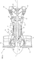
FIG. 1 is a schematic view of a turbofan gas turbine engine of a type employing the present invention; -
FIG. 2 is a schematic front sectional view of a rotatable component mounting arrangement of the present invention. - Referring to
FIG. 1 , a turbofangas turbine engine 5 has alongitudinal axis 7 about which therotors 8 rotate withinstator 9 which circumscribes the rotors. Afan 10 disposed at the engine inlet draws air into the engine. Alow pressure compressor 15 located immediately downstream offan 10 compresses air exhausted fromfan 10 and ahigh pressure compressor 20 located immediately downstream oflow pressure compressor 15, further compresses air received therefrom and exhausts such air tocombustors 25 disposed immediately downstream ofhigh pressure compressor 20. Combustors 25 receive fuel throughfuel injectors 30 and ignite the fuel/air mixture. The burning fuel-air mixture (working medium fluid) flows axially to ahigh pressure turbine 35 which extracts energy from the working medium fluid and in so doing, rotateshollow shaft 37, thereby driving the rotor ofhigh pressure compressor 20. The working medium fluid exiting thehigh pressure turbine 35 then enterslow pressure turbine 40, which extracts further energy from the working medium fluid. Thelow pressure turbine 40 provides power to drive thefan 10 andlow pressure compressor 15 throughlow pressure shaft 42, which is disposed interiorly of thehollow shaft 37, coaxial thereto. Working medium fluid exiting thelow pressure turbine 40 provides axial thrust for powering an associated aircraft (not shown) or a free turbine (also not shown). -
Bearings separate frame structures engine case 57, which defines the outer boundary of the engine'sstator 9 which circumscribesrotors 8. However, it will be appreciated that the present invention is also well suited for mid-turbine frame engine architectures wherein the upstream bearings for the low and high pressure turbines are mounted on a common frame structure disposed longitudinally (axially) between the high and low pressure turbines. - Referring to
FIGS. 1 and2 , a rotatable component 60 (shown inFIG. 1 ) such as a hub for the engine's fan, compressor or turbine is disposed in overlying relationship to an underlying base or mountingflange 65 which is fixed to one of the engine's shafts (seeFIG. 1 ) by any suitable technique such as welding or brazing or formed integrally therewith.Flange 65 is provided with a plurality ofapertures 70 disposed in a circular array at a radius R1 from an axis ofrotation 7.Hub 60 is provided with an equal number ofapertures apertures 75 are disposed at a radius R2 which is slightly less than radius R1 andapertures 80 are located at a radius R3 which is slightly greater than radius R1. Accordingly, it will be seen thatapertures hub 60 which surroundapertures close apertures 70 inmounting flange 65. By radially displacingapertures underlying apertures 70 in the manner described herein, portions ofhub 60 which surroundapertures apertures 70 in mounting flange 65 (i.e., reduce the aligned area between the apertures in the component and those in the base). A plurality of elongate fasteners such asbolts 85 extend through overlying pairs ofapertures clamp hub 60 to mountingflange 65. Partially closingapertures 70 inmounting flange 65 in the manner described, allowsbolts 85 to be maintained in radially interference fit with the overlying pairs of apertures in which they are received. As used herein, interference fit shall mean that the bolts are placed in surface-to-surface contact with the radially inner and outer surfaces ofapertures hub 60 due to for example an operational anomaly such as engine surge,hub 60 is prevented from radially shifting with respect to mountingflange 65. Since the bolts are received in the overlying apertures in the flange and hub in a radial interference fit, there is no need to machineapertures bolts 85 to eliminate any clearance between the bolts and the apertures which would be required with prior art manufacturing techniques. Accordingly, theapertures hub 60 and mountingflange 65 with normal tolerances thereby rendering the mounting arrangement herein implementable in a simple and cost-effective manner. That is, the radial displacement ofapertures aperture 70 is conveniently accomplished by providingapertures hub 60 andflange 65 with normal manufacturing tolerances, insertingbolts 85 into the aligned apertures, fixturing one of the flange or hub and heating the other of the flange or hub to radially offsetapertures aperture 70 thereby placingbolts 85 in the above-described interference fit with the pairs of overlying apertures. - While the present invention has been described within the context of mounting a bladed hub for a fan compressor or turbine stage on mounting flange disposed on gas turbine engine shaft, it will be appreciated that the present invention may be employed with equal efficacy for mounting any rotatable component on a gas turbine engine shaft. While the invention has been described and illustrated with twelve pairs of overlying apertures in the flange and hub, it will be appreciated that the exact number of apertures and size thereof will be determined by the size of the hub and mounting flange which will in turn be determined by the performance requirements of the engine in which the present invention is implemented. While the
elongate fasteners 85 have been described as bolts, it will be appreciated that equivalent fasteners, such as rivets, pins or other elongate fasteners, may be employed. Accordingly, it will be understood that various modifications to the preferred embodiment described herein may be made without departing from the present invention which is defined by the appended claims.
Claims (6)
- A mounting arrangement for a gas turbine engine (5), comprising:a rotatable base (65), fasteners (85) and a component (60) adapted to rotate about an axis of rotation of the gas turbine engine, the component being mounted on the rotatable base (65) by the fasteners extending through overlying apertures (70, 75, 80) in the component and the base, the overlying apertures including apertures (70) in the base being disposed at a radius R1 from the axis of rotation, the overlying apertures including apertures (75, 80) in the component being disposed at a radius R2 from the axis of rotation; and characterized by the overlying apertures including apertures in the component being disposed at a radius R3 from the axis of rotation, wherein one of the radii R2 and R3 is greater than the radius R1 and one of the radii R2 and R3 is less than the radius R1, thereby reducing an aligned area between the apertures in said component and said base such that said fasteners extending through the apertures are subjected to a radial interference fit within said overlying apertures in said component and base.
- The mounting arrangement of claim 1, wherein the component comprises a bladed hub (60).
- The mounting arrangement of claim 2, wherein the bladed hub comprises one of a fan hub, a compressor hub, and a turbine hub.
- The mounting arrangement of claim 1, wherein the base comprises a mounting flange (65).
- The mounting arrangement of claim 1, wherein one of the apertures in the base being disposed at the radius R1, the apertures in the component being disposed at the radius R2, and the apertures in the component being disposed at the radius R3, comprise a plurality of apertures disposed in a circular array.
- The mounting arrangement of claim 1, wherein the apertures in the component being disposed at the radius R2 and the apertures in the component being disposed at the radius R3 are staggered about a generally circular line having a radius from the axis of rotation that is equal to the radius R1.
Applications Claiming Priority (1)
| Application Number | Priority Date | Filing Date | Title |
|---|---|---|---|
| US12/846,371 US8668463B2 (en) | 2010-07-29 | 2010-07-29 | Rotatable component mount for a gas turbine engine |
Publications (3)
| Publication Number | Publication Date |
|---|---|
| EP2412940A2 EP2412940A2 (en) | 2012-02-01 |
| EP2412940A3 EP2412940A3 (en) | 2014-06-25 |
| EP2412940B1 true EP2412940B1 (en) | 2017-08-30 |
Family
ID=44510095
Family Applications (1)
| Application Number | Title | Priority Date | Filing Date |
|---|---|---|---|
| EP11176060.9A Active EP2412940B1 (en) | 2010-07-29 | 2011-07-29 | Rotatable component mount for a gas turbine engine |
Country Status (2)
| Country | Link |
|---|---|
| US (1) | US8668463B2 (en) |
| EP (1) | EP2412940B1 (en) |
Families Citing this family (6)
| Publication number | Priority date | Publication date | Assignee | Title |
|---|---|---|---|---|
| US9869190B2 (en) | 2014-05-30 | 2018-01-16 | General Electric Company | Variable-pitch rotor with remote counterweights |
| US10072510B2 (en) | 2014-11-21 | 2018-09-11 | General Electric Company | Variable pitch fan for gas turbine engine and method of assembling the same |
| US10502059B2 (en) | 2015-02-02 | 2019-12-10 | United Technologies Corporation | Alignment tie rod device and method of utilization |
| US10100653B2 (en) | 2015-10-08 | 2018-10-16 | General Electric Company | Variable pitch fan blade retention system |
| US11674435B2 (en) | 2021-06-29 | 2023-06-13 | General Electric Company | Levered counterweight feathering system |
| US11795964B2 (en) | 2021-07-16 | 2023-10-24 | General Electric Company | Levered counterweight feathering system |
Family Cites Families (15)
| Publication number | Priority date | Publication date | Assignee | Title |
|---|---|---|---|---|
| US3765795A (en) * | 1970-04-30 | 1973-10-16 | Gen Electric | Compositely formed rotors and their manufacture |
| US4304310A (en) | 1979-08-24 | 1981-12-08 | Smith International, Inc. | Drilling head |
| US5593277A (en) | 1995-06-06 | 1997-01-14 | General Electric Company | Smart turbine shroud |
| US6290442B1 (en) | 1997-09-18 | 2001-09-18 | Okabe Corporation, Inc. | Locking fastener assembly for threaded joint |
| US6148494A (en) | 1999-04-08 | 2000-11-21 | General Electric Company | Floating fastener tolerance method |
| KR20010007065A (en) | 1999-05-18 | 2001-01-26 | 제이 엘. 차스킨 | Inner shell radial pin geometry and mounting arrangement |
| DE10353376B4 (en) | 2003-11-14 | 2005-09-08 | Airbus Deutschland Gmbh | Device and method for the mechanical connection of two components |
| US8172512B2 (en) | 2008-04-23 | 2012-05-08 | Hamilton Sundstrand Corporation | Accessory gearbox system with compressor driven seal air supply |
| US8192143B2 (en) | 2008-05-21 | 2012-06-05 | United Technologies Corporation | Gearbox assembly |
| FR2931869B1 (en) * | 2008-05-29 | 2014-12-12 | Snecma | ANNULAR BRACKET FOR FIXING A ROTOR OR STATOR ELEMENT |
| US8210800B2 (en) | 2008-06-12 | 2012-07-03 | United Technologies Corporation | Integrated actuator module for gas turbine engine |
| US8113768B2 (en) | 2008-07-23 | 2012-02-14 | United Technologies Corporation | Actuated variable geometry mid-turbine frame design |
| DE102009013348A1 (en) * | 2009-03-16 | 2010-09-23 | Man Turbo Ag | Device and method for connecting a blade to a rotor shaft of a turbomachine |
| DE102010013551B4 (en) * | 2010-03-31 | 2016-12-08 | Dürr Systems Ag | Turbine rotor and drive turbine for a rotary atomizer and rotary atomizer |
| US20120126661A1 (en) * | 2010-11-18 | 2012-05-24 | Morgan Am&T | Replaceable Ground Ring For Slip Ring Assembly |
-
2010
- 2010-07-29 US US12/846,371 patent/US8668463B2/en active Active
-
2011
- 2011-07-29 EP EP11176060.9A patent/EP2412940B1/en active Active
Non-Patent Citations (1)
| Title |
|---|
| None * |
Also Published As
| Publication number | Publication date |
|---|---|
| US8668463B2 (en) | 2014-03-11 |
| EP2412940A3 (en) | 2014-06-25 |
| US20120027601A1 (en) | 2012-02-02 |
| EP2412940A2 (en) | 2012-02-01 |
Similar Documents
| Publication | Publication Date | Title |
|---|---|---|
| CN109538352B (en) | Outer drum rotor assembly and gas turbine engine | |
| EP2447472B1 (en) | Gas Turbine Engine Trim Balance | |
| EP1655457A1 (en) | Gas turbine engine and method of assembling same | |
| EP2971693B1 (en) | Gas turbine engine rotor disk-seal arrangement | |
| EP2412940B1 (en) | Rotatable component mount for a gas turbine engine | |
| EP3418610B1 (en) | Hydrostatic non-contact seal with weight reduction pocket | |
| CN108005786B (en) | Rotor shaft structure for gas turbine engine and method of assembling the same | |
| US10544793B2 (en) | Thermal isolation structure for rotating turbine frame | |
| EP3456916A1 (en) | Rotatable torque frame for gas turbine engine | |
| EP3181945B1 (en) | Damper seal installation features | |
| US10344622B2 (en) | Assembly with mistake proof bayoneted lug | |
| US5156525A (en) | Turbine assembly | |
| EP3179047B1 (en) | Method for reconfiguring a stator vane structure of a turbine engine | |
| EP2946117B1 (en) | Variable area vane arrangement with lever arm and turbine engine therewith | |
| US12000338B2 (en) | Electric machine within a turbine engine | |
| US11555408B2 (en) | Device for attaching blades in a contra-rotating turbine | |
| US12006834B1 (en) | Gas turbine engine having a tie rod |
Legal Events
| Date | Code | Title | Description |
|---|---|---|---|
| AK | Designated contracting states |
Kind code of ref document: A2 Designated state(s): AL AT BE BG CH CY CZ DE DK EE ES FI FR GB GR HR HU IE IS IT LI LT LU LV MC MK MT NL NO PL PT RO RS SE SI SK SM TR |
|
| AX | Request for extension of the european patent |
Extension state: BA ME |
|
| PUAI | Public reference made under article 153(3) epc to a published international application that has entered the european phase |
Free format text: ORIGINAL CODE: 0009012 |
|
| PUAL | Search report despatched |
Free format text: ORIGINAL CODE: 0009013 |
|
| AK | Designated contracting states |
Kind code of ref document: A3 Designated state(s): AL AT BE BG CH CY CZ DE DK EE ES FI FR GB GR HR HU IE IS IT LI LT LU LV MC MK MT NL NO PL PT RO RS SE SI SK SM TR |
|
| AX | Request for extension of the european patent |
Extension state: BA ME |
|
| RIC1 | Information provided on ipc code assigned before grant |
Ipc: F01D 5/02 20060101ALI20140516BHEP Ipc: F01D 25/28 20060101AFI20140516BHEP Ipc: F01D 5/06 20060101ALI20140516BHEP |
|
| 17P | Request for examination filed |
Effective date: 20141113 |
|
| RBV | Designated contracting states (corrected) |
Designated state(s): AL AT BE BG CH CY CZ DE DK EE ES FI FR GB GR HR HU IE IS IT LI LT LU LV MC MK MT NL NO PL PT RO RS SE SI SK SM TR |
|
| RAP1 | Party data changed (applicant data changed or rights of an application transferred) |
Owner name: UNITED TECHNOLOGIES CORPORATION |
|
| RIC1 | Information provided on ipc code assigned before grant |
Ipc: F01D 25/28 20060101AFI20170131BHEP Ipc: F01D 5/02 20060101ALI20170131BHEP Ipc: F01D 5/06 20060101ALI20170131BHEP |
|
| GRAP | Despatch of communication of intention to grant a patent |
Free format text: ORIGINAL CODE: EPIDOSNIGR1 |
|
| INTG | Intention to grant announced |
Effective date: 20170316 |
|
| GRAS | Grant fee paid |
Free format text: ORIGINAL CODE: EPIDOSNIGR3 |
|
| GRAA | (expected) grant |
Free format text: ORIGINAL CODE: 0009210 |
|
| AK | Designated contracting states |
Kind code of ref document: B1 Designated state(s): AL AT BE BG CH CY CZ DE DK EE ES FI FR GB GR HR HU IE IS IT LI LT LU LV MC MK MT NL NO PL PT RO RS SE SI SK SM TR |
|
| REG | Reference to a national code |
Ref country code: GB Ref legal event code: FG4D |
|
| REG | Reference to a national code |
Ref country code: CH Ref legal event code: EP |
|
| REG | Reference to a national code |
Ref country code: AT Ref legal event code: REF Ref document number: 923776 Country of ref document: AT Kind code of ref document: T Effective date: 20170915 |
|
| REG | Reference to a national code |
Ref country code: IE Ref legal event code: FG4D |
|
| REG | Reference to a national code |
Ref country code: DE Ref legal event code: R096 Ref document number: 602011041024 Country of ref document: DE |
|
| REG | Reference to a national code |
Ref country code: NL Ref legal event code: MP Effective date: 20170830 |
|
| REG | Reference to a national code |
Ref country code: LT Ref legal event code: MG4D |
|
| REG | Reference to a national code |
Ref country code: AT Ref legal event code: MK05 Ref document number: 923776 Country of ref document: AT Kind code of ref document: T Effective date: 20170830 |
|
| PG25 | Lapsed in a contracting state [announced via postgrant information from national office to epo] |
Ref country code: SE Free format text: LAPSE BECAUSE OF FAILURE TO SUBMIT A TRANSLATION OF THE DESCRIPTION OR TO PAY THE FEE WITHIN THE PRESCRIBED TIME-LIMIT Effective date: 20170830 Ref country code: LT Free format text: LAPSE BECAUSE OF FAILURE TO SUBMIT A TRANSLATION OF THE DESCRIPTION OR TO PAY THE FEE WITHIN THE PRESCRIBED TIME-LIMIT Effective date: 20170830 Ref country code: FI Free format text: LAPSE BECAUSE OF FAILURE TO SUBMIT A TRANSLATION OF THE DESCRIPTION OR TO PAY THE FEE WITHIN THE PRESCRIBED TIME-LIMIT Effective date: 20170830 Ref country code: NO Free format text: LAPSE BECAUSE OF FAILURE TO SUBMIT A TRANSLATION OF THE DESCRIPTION OR TO PAY THE FEE WITHIN THE PRESCRIBED TIME-LIMIT Effective date: 20171130 Ref country code: AT Free format text: LAPSE BECAUSE OF FAILURE TO SUBMIT A TRANSLATION OF THE DESCRIPTION OR TO PAY THE FEE WITHIN THE PRESCRIBED TIME-LIMIT Effective date: 20170830 Ref country code: HR Free format text: LAPSE BECAUSE OF FAILURE TO SUBMIT A TRANSLATION OF THE DESCRIPTION OR TO PAY THE FEE WITHIN THE PRESCRIBED TIME-LIMIT Effective date: 20170830 |
|
| PG25 | Lapsed in a contracting state [announced via postgrant information from national office to epo] |
Ref country code: GR Free format text: LAPSE BECAUSE OF FAILURE TO SUBMIT A TRANSLATION OF THE DESCRIPTION OR TO PAY THE FEE WITHIN THE PRESCRIBED TIME-LIMIT Effective date: 20171201 Ref country code: IS Free format text: LAPSE BECAUSE OF FAILURE TO SUBMIT A TRANSLATION OF THE DESCRIPTION OR TO PAY THE FEE WITHIN THE PRESCRIBED TIME-LIMIT Effective date: 20171230 Ref country code: RS Free format text: LAPSE BECAUSE OF FAILURE TO SUBMIT A TRANSLATION OF THE DESCRIPTION OR TO PAY THE FEE WITHIN THE PRESCRIBED TIME-LIMIT Effective date: 20170830 Ref country code: LV Free format text: LAPSE BECAUSE OF FAILURE TO SUBMIT A TRANSLATION OF THE DESCRIPTION OR TO PAY THE FEE WITHIN THE PRESCRIBED TIME-LIMIT Effective date: 20170830 Ref country code: ES Free format text: LAPSE BECAUSE OF FAILURE TO SUBMIT A TRANSLATION OF THE DESCRIPTION OR TO PAY THE FEE WITHIN THE PRESCRIBED TIME-LIMIT Effective date: 20170830 Ref country code: BG Free format text: LAPSE BECAUSE OF FAILURE TO SUBMIT A TRANSLATION OF THE DESCRIPTION OR TO PAY THE FEE WITHIN THE PRESCRIBED TIME-LIMIT Effective date: 20171130 |
|
| PG25 | Lapsed in a contracting state [announced via postgrant information from national office to epo] |
Ref country code: NL Free format text: LAPSE BECAUSE OF FAILURE TO SUBMIT A TRANSLATION OF THE DESCRIPTION OR TO PAY THE FEE WITHIN THE PRESCRIBED TIME-LIMIT Effective date: 20170830 |
|
| PG25 | Lapsed in a contracting state [announced via postgrant information from national office to epo] |
Ref country code: PL Free format text: LAPSE BECAUSE OF FAILURE TO SUBMIT A TRANSLATION OF THE DESCRIPTION OR TO PAY THE FEE WITHIN THE PRESCRIBED TIME-LIMIT Effective date: 20170830 Ref country code: RO Free format text: LAPSE BECAUSE OF FAILURE TO SUBMIT A TRANSLATION OF THE DESCRIPTION OR TO PAY THE FEE WITHIN THE PRESCRIBED TIME-LIMIT Effective date: 20170830 Ref country code: CZ Free format text: LAPSE BECAUSE OF FAILURE TO SUBMIT A TRANSLATION OF THE DESCRIPTION OR TO PAY THE FEE WITHIN THE PRESCRIBED TIME-LIMIT Effective date: 20170830 Ref country code: DK Free format text: LAPSE BECAUSE OF FAILURE TO SUBMIT A TRANSLATION OF THE DESCRIPTION OR TO PAY THE FEE WITHIN THE PRESCRIBED TIME-LIMIT Effective date: 20170830 |
|
| PG25 | Lapsed in a contracting state [announced via postgrant information from national office to epo] |
Ref country code: EE Free format text: LAPSE BECAUSE OF FAILURE TO SUBMIT A TRANSLATION OF THE DESCRIPTION OR TO PAY THE FEE WITHIN THE PRESCRIBED TIME-LIMIT Effective date: 20170830 Ref country code: SK Free format text: LAPSE BECAUSE OF FAILURE TO SUBMIT A TRANSLATION OF THE DESCRIPTION OR TO PAY THE FEE WITHIN THE PRESCRIBED TIME-LIMIT Effective date: 20170830 Ref country code: IT Free format text: LAPSE BECAUSE OF FAILURE TO SUBMIT A TRANSLATION OF THE DESCRIPTION OR TO PAY THE FEE WITHIN THE PRESCRIBED TIME-LIMIT Effective date: 20170830 Ref country code: SM Free format text: LAPSE BECAUSE OF FAILURE TO SUBMIT A TRANSLATION OF THE DESCRIPTION OR TO PAY THE FEE WITHIN THE PRESCRIBED TIME-LIMIT Effective date: 20170830 |
|
| REG | Reference to a national code |
Ref country code: DE Ref legal event code: R097 Ref document number: 602011041024 Country of ref document: DE |
|
| REG | Reference to a national code |
Ref country code: FR Ref legal event code: PLFP Year of fee payment: 8 |
|
| PLBE | No opposition filed within time limit |
Free format text: ORIGINAL CODE: 0009261 |
|
| STAA | Information on the status of an ep patent application or granted ep patent |
Free format text: STATUS: NO OPPOSITION FILED WITHIN TIME LIMIT |
|
| 26N | No opposition filed |
Effective date: 20180531 |
|
| PG25 | Lapsed in a contracting state [announced via postgrant information from national office to epo] |
Ref country code: SI Free format text: LAPSE BECAUSE OF FAILURE TO SUBMIT A TRANSLATION OF THE DESCRIPTION OR TO PAY THE FEE WITHIN THE PRESCRIBED TIME-LIMIT Effective date: 20170830 |
|
| REG | Reference to a national code |
Ref country code: CH Ref legal event code: PL |
|
| PG25 | Lapsed in a contracting state [announced via postgrant information from national office to epo] |
Ref country code: MC Free format text: LAPSE BECAUSE OF FAILURE TO SUBMIT A TRANSLATION OF THE DESCRIPTION OR TO PAY THE FEE WITHIN THE PRESCRIBED TIME-LIMIT Effective date: 20170830 Ref country code: LU Free format text: LAPSE BECAUSE OF NON-PAYMENT OF DUE FEES Effective date: 20180729 |
|
| REG | Reference to a national code |
Ref country code: BE Ref legal event code: MM Effective date: 20180731 |
|
| PG25 | Lapsed in a contracting state [announced via postgrant information from national office to epo] |
Ref country code: LI Free format text: LAPSE BECAUSE OF NON-PAYMENT OF DUE FEES Effective date: 20180731 Ref country code: CH Free format text: LAPSE BECAUSE OF NON-PAYMENT OF DUE FEES Effective date: 20180731 |
|
| REG | Reference to a national code |
Ref country code: IE Ref legal event code: MM4A |
|
| PG25 | Lapsed in a contracting state [announced via postgrant information from national office to epo] |
Ref country code: BE Free format text: LAPSE BECAUSE OF NON-PAYMENT OF DUE FEES Effective date: 20180731 |
|
| PG25 | Lapsed in a contracting state [announced via postgrant information from national office to epo] |
Ref country code: IE Free format text: LAPSE BECAUSE OF NON-PAYMENT OF DUE FEES Effective date: 20180729 |
|
| PG25 | Lapsed in a contracting state [announced via postgrant information from national office to epo] |
Ref country code: MT Free format text: LAPSE BECAUSE OF NON-PAYMENT OF DUE FEES Effective date: 20180729 |
|
| PG25 | Lapsed in a contracting state [announced via postgrant information from national office to epo] |
Ref country code: TR Free format text: LAPSE BECAUSE OF FAILURE TO SUBMIT A TRANSLATION OF THE DESCRIPTION OR TO PAY THE FEE WITHIN THE PRESCRIBED TIME-LIMIT Effective date: 20170830 |
|
| PG25 | Lapsed in a contracting state [announced via postgrant information from national office to epo] |
Ref country code: PT Free format text: LAPSE BECAUSE OF FAILURE TO SUBMIT A TRANSLATION OF THE DESCRIPTION OR TO PAY THE FEE WITHIN THE PRESCRIBED TIME-LIMIT Effective date: 20170830 Ref country code: HU Free format text: LAPSE BECAUSE OF FAILURE TO SUBMIT A TRANSLATION OF THE DESCRIPTION OR TO PAY THE FEE WITHIN THE PRESCRIBED TIME-LIMIT; INVALID AB INITIO Effective date: 20110729 |
|
| PG25 | Lapsed in a contracting state [announced via postgrant information from national office to epo] |
Ref country code: CY Free format text: LAPSE BECAUSE OF FAILURE TO SUBMIT A TRANSLATION OF THE DESCRIPTION OR TO PAY THE FEE WITHIN THE PRESCRIBED TIME-LIMIT Effective date: 20170830 Ref country code: MK Free format text: LAPSE BECAUSE OF NON-PAYMENT OF DUE FEES Effective date: 20170830 |
|
| PG25 | Lapsed in a contracting state [announced via postgrant information from national office to epo] |
Ref country code: AL Free format text: LAPSE BECAUSE OF FAILURE TO SUBMIT A TRANSLATION OF THE DESCRIPTION OR TO PAY THE FEE WITHIN THE PRESCRIBED TIME-LIMIT Effective date: 20170830 |
|
| REG | Reference to a national code |
Ref country code: DE Ref legal event code: R081 Ref document number: 602011041024 Country of ref document: DE Owner name: RAYTHEON TECHNOLOGIES CORPORATION (N.D.GES.D.S, US Free format text: FORMER OWNER: UNITED TECHNOLOGIES CORPORATION, FARMINGTON, CONN., US |
|
| P01 | Opt-out of the competence of the unified patent court (upc) registered |
Effective date: 20230519 |
|
| PGFP | Annual fee paid to national office [announced via postgrant information from national office to epo] |
Ref country code: DE Payment date: 20230620 Year of fee payment: 13 |
|
| PGFP | Annual fee paid to national office [announced via postgrant information from national office to epo] |
Ref country code: GB Payment date: 20240620 Year of fee payment: 14 |
|
| PGFP | Annual fee paid to national office [announced via postgrant information from national office to epo] |
Ref country code: FR Payment date: 20240619 Year of fee payment: 14 |