EP2412917A1 - Hydraulic bi-directional rotary isolation valve - Google Patents
Hydraulic bi-directional rotary isolation valve Download PDFInfo
- Publication number
- EP2412917A1 EP2412917A1 EP10177230A EP10177230A EP2412917A1 EP 2412917 A1 EP2412917 A1 EP 2412917A1 EP 10177230 A EP10177230 A EP 10177230A EP 10177230 A EP10177230 A EP 10177230A EP 2412917 A1 EP2412917 A1 EP 2412917A1
- Authority
- EP
- European Patent Office
- Prior art keywords
- valve
- wedgelock
- directional
- valve element
- seat
- Prior art date
- Legal status (The legal status is an assumption and is not a legal conclusion. Google has not performed a legal analysis and makes no representation as to the accuracy of the status listed.)
- Granted
Links
Images


Classifications
-
- E—FIXED CONSTRUCTIONS
- E21—EARTH DRILLING; MINING
- E21B—EARTH DRILLING, e.g. DEEP DRILLING; OBTAINING OIL, GAS, WATER, SOLUBLE OR MELTABLE MATERIALS OR A SLURRY OF MINERALS FROM WELLS
- E21B34/00—Valve arrangements for boreholes or wells
- E21B34/06—Valve arrangements for boreholes or wells in wells
- E21B34/10—Valve arrangements for boreholes or wells in wells operated by control fluid supplied from outside the borehole
- E21B34/102—Valve arrangements for boreholes or wells in wells operated by control fluid supplied from outside the borehole with means for locking the closing element in open or closed position
-
- E—FIXED CONSTRUCTIONS
- E21—EARTH DRILLING; MINING
- E21B—EARTH DRILLING, e.g. DEEP DRILLING; OBTAINING OIL, GAS, WATER, SOLUBLE OR MELTABLE MATERIALS OR A SLURRY OF MINERALS FROM WELLS
- E21B2200/00—Special features related to earth drilling for obtaining oil, gas or water
- E21B2200/04—Ball valves
Definitions
- This invention relates to a valve that may be used in wells during drilling operations or may be used in any application requiring a valve having a large bore compared with its outside diameter. More particularly, a hydraulically operated valve having a sleeve to protect the valve element when open and a mechanism for locking the valve closed is provided.
- Drilling of wells in an underbalanced or balanced pressure condition has well-known advantages.
- pressure in the formation being drilled is equal to or greater than pressure in the wellbore.
- pressure in the wellbore must be controlled to prevent influx of fluids from a formation into the wellbore.
- the usual remedy of preventing influx of fluid from a formation may negate the advantages of balanced or underbalanced drilling. Therefore, downhole valves have been developed to isolate fluid pressure below the valve. They have been variously called “Downhole Deployment Valves” (DDV) or “Downhole Isolation Valves” (DIV).
- DDV Downhole Deployment Valves
- DIV Downhole Isolation Valves
- a DCIV is placed in a casing at a selected depth, considering conditions that may be encountered in drilling the well.
- the valve is normally placed in an intermediate casing string, and the effective Outside Diameter (OD) of the valve is limited by the Inside Diameter (ID) of the surface casing through which it must pass.
- ID Inside Diameter
- the valve preferably will be a full-opening (have a bore at least equal to the ID of the 7-inch (178 mm) casing, about 6.276 inch (159 mm), or at least be as large as the drill bit to be used) and must pass through the drift diameter of the surface casing, which may be 8.5 inches (216 mm). Therefore, the valve must be designed to severely limit the thickness of the valve body while being large enough for a bit to pass through.
- a DCIV is disclosed in U.S. Pat. No. 6,209,663 .
- a flapper valve is illustrated, but other types of valves, such as ball valves or other rotary valves are disclosed.
- the valves may be operated hydraulically or by biasing means (e.g., springs).
- U.S. Pat. No. 6,167,974 discloses a flapper-type DCIV valve that is operated by a shifting device that is carried on a drill bit and deposited in the valve when the drill string is tripped out of the well.
- valves designed for downhole isolation may also be used for a variety of purposes.
- valves requiring a minimum of wall thickness between the interior passage through the valve and the exterior surface of the valve may be needed for a variety of applications, such as: conventional products pipelines; piping in plants such as power plants, refineries or chemical plants; marine installations; biomedical devices and other devices where a thin-wall, stemless valve that can be operated by remote hydraulic pressure is needed.
- the present invention provides a valve as set out in the accompanying claims.
- the present invention (at least in preferred embodiments) provides a hydraulically activated, bi-directional (will isolate fluid pressure in either direction), rotary- and linear-motion valve, referred to herein as the HBRL Valve.
- the valve element is mounted on trunnions. As the trunnions move along a track, the valve element is rotated from a position parallel to the axis of the bore of the valve (open) to a position perpendicular to the axis of the bore (closing). Further motion along the track seats the valve element.
- the trunnions are moved by force from a sleeve moving in response to hydraulic pressure. A second sleeve is moved to protect the valve mechanism when the valve is open. After closing, the valve is locked into position to isolate fluid pressure differential across the valve in either direction.
- FIG. 1 illustrates a well 10 that is being drilled.
- Surface casing 12 has been placed in the well.
- the inside diameter 21 of HBRL valve 20 must be large enough to allow passage of bit 16 on drill pipe 15.
- the HBRL valve disclosed here is adapted to allow less difference in diameter between the inside diameter of valve 20 and the inside diameter of casing 14 than is allowed by downhole isolation valves cited in the references disclosed above. Hydraulic lines in bundle 19 are connected between HBRL valve 20 and a hydraulic pressure control system at a selected location (not shown).
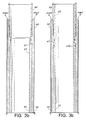
- the elongated HBRL valve assembly is illustrated in sectional views 2a - 2f and 3a - 3f.
- the valve In FIG. 2 , the valve is in the open position and in FIG. 3 it is in the closed position.
- Lines dividing the tools into segments from uphole to downhole are labelled as lines A to E at the bottom and top of each figure a to f. Because some parts of the valve assembly extend over multiple drawings, operation of the valve may be better understood if drawings of FIGS. 2a - f and FIGS. 3a - f are laid end-to-end according to the dividing lines.
- upper connection housing 40 is shown. Threads on upper connection housing 40 are adapted for joining to casing in which the HBRL valve 20 is to be employed.
- the top of protective sleeve 42 moves to within the upper connection housing, as shown in FIG. 3a .
- connection housing 40 is joined to hydraulic connection housing 44. This joining may be by a threaded connection, as shown.
- Hydraulic connection housing 44 contains port A and port B. These ports are adapted for connection to hydraulic lines shown bundled together as 19 in FIG. 1 .
- Protective sleeve 42 is disposed toward the lower or downhole end of the valve assembly in FIG. 2b .
- Protective sleeve 42 covers the "Wedgelock" valve element when in the open position, as will be shown in more detail below. (Wedgelock is used to identify the valve element. It may be formed by machining two curved surfaces from round stock, the surfaces being separated by the selected thickness of the valve element to form a "saddle-like" shape.
- protective sleeve 42 is disposed toward the uphole direction. Sleeve 42 may be moved downhole by application of hydraulic pressure through port B across o-ring seal 42A, as shown in FIG. 3b .
- FIGS. 2c and 3c the joining of hydraulic connection housing 44 and coupling housing 48 is shown. This joining may be by a threaded connection. Hydraulic conduits from port A and port B extend through these housings.
- FIG. 3c showing the valve in the closed position, protective sleeve 42 extends to just uphole from the Wedgelock assembly, which will be shown below, and in FIG. 2c protective sleeve 42 extends through the figure and into the lower segment of the tool, so as to cover the Wedgelock assembly when it is in the open position.
- coupling housing 48 is shown joined to valve seat housing 50.
- Valve seat housing 50 also provides hydraulic conduits connected to port A and port B.
- Relief valve 52 may be provided in valve seat housing 50. The function of relief valve 52 is to allow fluid to pass through HBRL valve 20 if pressure below the HBRL valve exceeds a selected value.
- Upper split ring 46 is also provided in coupling housing 48. The function of split ring 46 will be described below.
- FIGS. 2d and 3d the joining of valve seat housing 50 and Wedgelock assembly housing 54, the joining of Wedgelock assembly housing 54 and coupling housing 68, and the joining of coupling housing 68 and lower housing 72 are shown. These joinings may be by a threaded connection. Wedgelock assembly housing 54 and coupling housing 68 also provide hydraulic conduits through the housings, as shown.
- FIG. 2d shows that protective sleeve 42 extends through to a downhole location covering cam assembly 58 when the valve is in an open position. Protective sleeve 42 is displaced to an uphole position when the valve is closed, as shown by its absence in FIG. 3d .
- Valve seat 51 shown in FIG.
- Wedgelock locking sleeve 74 is displaced uphole in FIG. 3d , compared with FIG. 2d , by hydraulic pressure as described below.
- Cam locking fingers 67 are provided on cam assembly 58, which is engaged with cam finger unlocking grooves 55a on Wedgelock locking sleeve 74, as shown in FIG. 2d .
- Wedgelock locking sleeve 74 is displaced uphole in FIG..
- Lower split ring 66 is provided in a groove in locking coupling housing 68. The function of lower split ring 66 will be described below.
- Wedgelock locking sleeve 74 is driven uphole by hydraulic pressure across o-ring 75. Finger locking sleeve 70 is displaced with Wedgelock locking sleeve 74. Movement uphole continues until o-ring 75 reaches by-pass groove 76. At this time movement of Wedgelock locking sleeve 74 ceases and movement of finger locking sleeve 70 continues upward, driven by hydraulic pressure, until the uphole end of finger locking sleeve 70 locks over locking fingers 71 of coupling housing 68 as shown in FIG. 2e and 3e .
- the distance from the initial position of o-ring 75 to by-pass groove 76 may be the same as the distance from finger locking groove 77 on Wedgelock locking sleeve 74 to the lower end of locking fingers 71.
- FIGS. 2f and 3f show lower housing 72 with threads adapted to joining with the casing.
- Wedgelock locking sleeve 74 is shown in FIG. 2f in its downhole position when the valve assembly is open.
- FIG. 4 shows a detail drawing of cam assembly 58 when the valve is open.
- Cam assembly 58 comprises control arm 64, trunnions 62, guide rails 60 and pivot point 61.
- trunnion 62 is moved uphole by cam assembly 58, causing control arm 64 to pivot as trunnion 62 moves along guide rails 60.
- Wedgelock 56 is still in a completely open position, oriented parallel to the axis to the valve.
- trunnion 62 has moved along guide rails 60 to pivot point 61.
- Trunnion 62 is designed to interact with pivot point 61 so as to cause rotation of Wedgelock 56.
- FIG. 6 partial rotation of Wedgelock 56 has occurred and in FIG. 7 a 90° rotation of Wedgelock 56 has occurred and it is now in an orientation to seat on valve seat 51.
- Continued movement of Wedgelock 56 towards the seating position is made possible by linear movement of trunnion 62 along guide rails 60.
- FIG. 8 is a cross-section view of guide rail 60. It is adapted to be welded or otherwise fastened to the inside diameter of Wedgelock assembly housing 54. Alternately, guide rail 60 can be an intrinsic part of the Wedgelock assembly housing 54. Guide rails 60 are adapted to receive trunnions 62. One embodiment of interlocking surfaces is illustrated in FIG. 15 , which is the cross-section view identified in FIG. 3d . It should be understood that alternative guide rail and cam assemblies may be used. Trunnions 62 are attached to Wedgelock 56, which is the valve seating element as shown in FIG. 14 . When Wedgelock 56 is used in casing, it is preferably designed to withstand differential pressure expected in a well in both directions. Preferably the sealing surface of Wedgelock 56 is metal, but, alternatively, polymeric valve seats such as known in industry may be used.
- FIG. 8 shows a cross-section view of guide rails 60.
- FIG. 9 shows an elevation view of guide rails 60, which includes pivot point 61, adapted to interact with a trunnion to cause rotation.
- FIG. 10 shows a view of one embodiment of a trunnion and guide.
- FIG. 11 shows a side view of trunnion 62 and guide 63. The cross-section indicated in FIG. 11 is shown in FIG. 12 .
- Pivot point contact 63a on guide 63 is adapted to contact guide rail 60 at pivot point 61 so as to rotate Wedgelock 56 into an orientation for seating.
- FIG. 13 shows an isometric view of control arm 64, having opening 64a adapted to receive trunnion 62.
- FIG. 14 shows Wedgelock 56 having trunnions 62 and valve seating area 57.
- Wedgelock 56 can be comprised of one or multiple sectional parts mounted on a plurality of trunnions around the outer shell of the valve element. Such arrangement and others will not change the functionality of HBRL valve 20.
- FIG. 16 shows an isometric view of upper split ring 46.
- Upper and lower split rings are used for functions to be described below.
- HBRL valve 20 To move HBRL valve 20 from an open position to a closed position after drill bit 16 ( FIG. 1 ) is raised to a location above the valve, hydraulic pressure is applied to port A through a hydraulic line in bundle 19 as shown in FIG. 1 .
- the first operation in the sequence of closing is application of hydraulic pressure to port A, which shifts protective sleeve 42 until it shoulder limits on hydraulic connection housing 44 at shoulder 43. This movement of protective sleeve 42 causes engagement with upper split ring 46, which is positioned in a groove on coupling housing 48. Hydraulic pressure at port A is then further increased until it overcomes the force of lower split ring 66 in locking coupling housing 68. When lower split ring 66 disengages, Wedgelock locking sleeve 74 moves uphole.
- Wedgelock locking sleeve 74 engages cam assembly 58 at cam finger unlocking groove 55A with locking fingers 67.
- Cam assembly 58 moves Wedgelock 56 uphole until it has seated in valve seat 51. Rotation of Wedgelock 56 by 90° occurs as cam assembly 58 moves uphole, as described in FIGS. 4 to 7 . At this point the valve is seated but not locked in position.
- Hydraulic pressure is then increased again at port A and it begins to push Wedgelock locking sleeve 74 uphole locking finger 67 disengaging the cam finger unlocking groove 55A causing linear movement at the Wedgelock locking sleeve 74 until it is seated against the back side of Wedgelock 56, at which time locking fingers 67 engage cam finger locking groove 55B
- o-ring 75 on Wedgelock locking sleeve 74 will be located at fluid by-pass grooves 76 of lower housing 72. Fluid will flow around o-ring 75 and shift finger locking sleeve 70 onto locking fingers 71 of coupling housing 68. At this point the valve is fully seated and locked.
- HBRL valve 20 To operate HBRL valve 20 from a closed position to an open position, hydraulic pressure is applied to port B on hydraulic connection housing 44. Pressure is applied to the opposite side of finger locking sleeve 70 until it unlocks from coupling housing 68 and begins to move downhole. Finger locking sleeve 70 will continue movement until it has reached shoulder limit 78 on Wedgelock locking sleeve 74. Both pieces will then move simultaneously downhole. Still engaged with Wedgelock locking sleeve 74, cam assembly 58 disengages from its seated position and also moves downhole until cam assembly 58 reaches shoulder limit 69 on coupling housing 68. Lower snap ring 66 will reengage at this point. Pressure is increased further until protective sleeve 42 overcomes the force of upper split ring 46. Protective sleeve 42 then shifts downhole until it reaches shoulder limit 41 against the ID of coupling housing 48. At this time the valve is fully opened and Wedgelock 56 is covered by protective sleeve 42.
- the HBRL valve When used in other applications, it will normally be adapted to operate in confined spaces where the small difference between outside and inside dimensions of the valve is important. The difference achievable with the HBRL valve is dependent on pressure requirements for the valve.
- the valve When used as a DCIV, as shown in FIG. 1 , the valve may be constructed to withstand thousands of psi of differential pressure and still provide an inside diameter of 6.276 inches (159 mm) and an outside diameter of 8.5 inches (216 mm).
- a valve for operation in a tube comprising a housing adapted for joining to the tube, a valve element having a curved surface for sealing and a pair of trunnions on the valve element, each of the trunnions having a guiding element attached thereto, a pair of tracks adapted to receive the guiding element attached to the trunnions, each of the tracks having a pivot point for rotating the orientation of the valve element, a valve seating surface, a protective sleeve adapted to move over the valve element when it is in an open position, and a locking device for locking the valve element in a closed position.
- the tube may be a casing for placement in a well.
- the curved surface of the valve element may be formed from a metal or from a polymeric material.
- a bypass valve may vent excess pressure across the valve.
Abstract
Description
- This invention relates to a valve that may be used in wells during drilling operations or may be used in any application requiring a valve having a large bore compared with its outside diameter. More particularly, a hydraulically operated valve having a sleeve to protect the valve element when open and a mechanism for locking the valve closed is provided.
- Drilling of wells in an underbalanced or balanced pressure condition has well-known advantages. In this condition, pressure in the formation being drilled is equal to or greater than pressure in the wellbore. When there is a need to withdraw the drill pipe from the well, pressure in the wellbore must be controlled to prevent influx of fluids from a formation into the wellbore. The usual remedy of preventing influx of fluid from a formation---by increasing fluid density in the wellbore---may negate the advantages of balanced or underbalanced drilling. Therefore, downhole valves have been developed to isolate fluid pressure below the valve. They have been variously called "Downhole Deployment Valves" (DDV) or "Downhole Isolation Valves" (DIV). Technical literature includes reports of the usage of such valves in Under-Balanced Drilling (UBD) For example, SPE 77240-MS, "Downhole Deployment Valve Addresses Problems Associated with Tripping Drill Pipe During Underbalanced Drilling Operations," S. Herbal et al, 2002, described uses of such valves in industry. The DDV or DIV as a tool in the broad area of "Managed Pressure Drilling" can be generally surmised from the survey lecture "Managed Pressure Drilling," by D. Hannagan, SPE 112803, 2007. There it is listed under "Other Tools" and called a "Downhole Casing Isolation Valve - (DCIV)" or "Downhole Deployment Valve." Services and products for providing Managed Pressure Drilling have been commercialized by AtBalance of Houston, Texas, Weatherford International, Inc. of Houston, Texas and other companies.
- A DCIV is placed in a casing at a selected depth, considering conditions that may be encountered in drilling the well. The valve is normally placed in an intermediate casing string, and the effective Outside Diameter (OD) of the valve is limited by the Inside Diameter (ID) of the surface casing through which it must pass. For example, in a 7-inch (178 mm) intermediate casing, the valve preferably will be a full-opening (have a bore at least equal to the ID of the 7-inch (178 mm) casing, about 6.276 inch (159 mm), or at least be as large as the drill bit to be used) and must pass through the drift diameter of the surface casing, which may be 8.5 inches (216 mm). Therefore, the valve must be designed to severely limit the thickness of the valve body while being large enough for a bit to pass through.
- A DCIV is disclosed in
U.S. Pat. No. 6,209,663 . A flapper valve is illustrated, but other types of valves, such as ball valves or other rotary valves are disclosed. The valves may be operated hydraulically or by biasing means (e.g., springs).U.S. Pat. No. 6,167,974 discloses a flapper-type DCIV valve that is operated by a shifting device that is carried on a drill bit and deposited in the valve when the drill string is tripped out of the well. - Prior art valves relying on a flapper mechanism have been commercially successful, but improvements in reliability and absence of leakage are needed. A rotary valve having minimum difference between outside diameter and inside diameter is needed. The ability of the valve to seal with differential pressure in two directions is also preferred.
- It should be understood that valves designed for downhole isolation may also be used for a variety of purposes. In wells, there may be a need to open or close a valve to control pressure near the bottom of the well when the hydrostatic pressure of fluid in the well is higher than desired, or there may be a need to isolate pressure in a well bore drilled from another well bore. In industry, valves requiring a minimum of wall thickness between the interior passage through the valve and the exterior surface of the valve may be needed for a variety of applications, such as: conventional products pipelines; piping in plants such as power plants, refineries or chemical plants; marine installations; biomedical devices and other devices where a thin-wall, stemless valve that can be operated by remote hydraulic pressure is needed.
- The present invention provides a valve as set out in the accompanying claims.
- The present invention (at least in preferred embodiments) provides a hydraulically activated, bi-directional (will isolate fluid pressure in either direction), rotary- and linear-motion valve, referred to herein as the HBRL Valve. The valve element is mounted on trunnions. As the trunnions move along a track, the valve element is rotated from a position parallel to the axis of the bore of the valve (open) to a position perpendicular to the axis of the bore (closing). Further motion along the track seats the valve element. The trunnions are moved by force from a sleeve moving in response to hydraulic pressure. A second sleeve is moved to protect the valve mechanism when the valve is open. After closing, the valve is locked into position to isolate fluid pressure differential across the valve in either direction.
- Some preferred embodiments of the present invention will now be described by way of example only and with reference to the accompanying drawings, in which:
-
FIG. 1 is a sketch of a well having a hydraulically operated HBRL valve used as a DCIV in an intermediate casing; -
FIGS. 2a - 2f illustrate the valve in the open position; -
FIGS. 3a - 3f illustrate the valve in the closed position; -
FIG. 4 is a detailed view of a "Wedgelock" valve assembly in the open position; -
FIG. 5 is a detailed view of the Wedgelock valve assembly when the "Wedgelock" is moved toward the closed position but is not rotated; -
FIG. 6 is a detailed view of the Wedgelock assembly when the Wedgelock has partially rotated into a closing position; -
FIG. 7 is a detailed view of the Wedgelock assembly when the valve is in the closed position; -
FIG. 8 is an end-view of a guide rail for the trunnion of the Wedgelock; -
FIG. 9 is an elevation view of a guide rail for the trunnion of the Wedgelock; -
FIG. 10 is an elevation view of a trunnion for the valve from a first direction; -
FIG. 11 is a side view of a trunnion adapted to move in a guide rail; -
FIG. 12 is a cross-section view of a trunnion as indicated inFIG. 11 ; -
FIG. 13 is an isometric view of the control arm of the Wedgelock assembly; -
FIG. 14 is an elevation view of the Wedgelock with the trunnion; -
FIG. 15 is a cross-sectional view along the axis of the Wedgelock valve assembly as indicated inFIG. 3d ; and -
FIG. 16 is an isometric view of a split ring of the valve assembly. -
FIG. 1 illustrates a well 10 that is being drilled.Surface casing 12 has been placed in the well. Intermediate casing 14, containing a HBRL (Hydraulic Bidirectional Rotary-Linear)valve 20, used as a Downhole Casing Isolation Valve (DCIV), has also been placed in the well. Theinside diameter 21 ofHBRL valve 20 must be large enough to allow passage ofbit 16 ondrill pipe 15. The HBRL valve disclosed here is adapted to allow less difference in diameter between the inside diameter ofvalve 20 and the inside diameter of casing 14 than is allowed by downhole isolation valves cited in the references disclosed above. Hydraulic lines inbundle 19 are connected betweenHBRL valve 20 and a hydraulic pressure control system at a selected location (not shown). - The elongated HBRL valve assembly is illustrated in sectional views 2a - 2f and 3a - 3f. In
FIG. 2 , the valve is in the open position and inFIG. 3 it is in the closed position. Lines dividing the tools into segments from uphole to downhole are labelled as lines A to E at the bottom and top of each figure a to f. Because some parts of the valve assembly extend over multiple drawings, operation of the valve may be better understood if drawings ofFIGS. 2a - f and FIGS. 3a - f are laid end-to-end according to the dividing lines. - Referring to
FIG. 2a ,upper connection housing 40 is shown. Threads onupper connection housing 40 are adapted for joining to casing in which theHBRL valve 20 is to be employed. When theHBRL valve 20 is in a closed position, the top ofprotective sleeve 42 moves to within the upper connection housing, as shown inFIG. 3a . - In
FIGS 2b and. 3b ,upper connection housing 40 is joined tohydraulic connection housing 44. This joining may be by a threaded connection, as shown.Hydraulic connection housing 44 contains port A and port B. These ports are adapted for connection to hydraulic lines shown bundled together as 19 inFIG. 1 .Protective sleeve 42 is disposed toward the lower or downhole end of the valve assembly inFIG. 2b .Protective sleeve 42 covers the "Wedgelock" valve element when in the open position, as will be shown in more detail below. (Wedgelock is used to identify the valve element. It may be formed by machining two curved surfaces from round stock, the surfaces being separated by the selected thickness of the valve element to form a "saddle-like" shape. The thickness is selected according to differential pressure expected across the valve.) InFIG. 3b ,protective sleeve 42 is disposed toward the uphole direction.Sleeve 42 may be moved downhole by application of hydraulic pressure through port B across o-ring seal 42A, as shown inFIG. 3b . - Referring to
FIGS. 2c and 3c , the joining ofhydraulic connection housing 44 andcoupling housing 48 is shown. This joining may be by a threaded connection. Hydraulic conduits from port A and port B extend through these housings. InFIG. 3c , showing the valve in the closed position,protective sleeve 42 extends to just uphole from the Wedgelock assembly, which will be shown below, and inFIG. 2c protective sleeve 42 extends through the figure and into the lower segment of the tool, so as to cover the Wedgelock assembly when it is in the open position. Also inFIGS. 2c and 3c , couplinghousing 48 is shown joined tovalve seat housing 50.Valve seat housing 50 also provides hydraulic conduits connected to port A and portB. Relief valve 52 may be provided invalve seat housing 50. The function ofrelief valve 52 is to allow fluid to pass throughHBRL valve 20 if pressure below the HBRL valve exceeds a selected value. -
Upper split ring 46 is also provided incoupling housing 48. The function ofsplit ring 46 will be described below. - Referring to
FIGS. 2d and 3d , the joining ofvalve seat housing 50 andWedgelock assembly housing 54, the joining ofWedgelock assembly housing 54 andcoupling housing 68, and the joining of couplinghousing 68 andlower housing 72 are shown. These joinings may be by a threaded connection.Wedgelock assembly housing 54 andcoupling housing 68 also provide hydraulic conduits through the housings, as shown.FIG. 2d shows thatprotective sleeve 42 extends through to a downhole location coveringcam assembly 58 when the valve is in an open position.Protective sleeve 42 is displaced to an uphole position when the valve is closed, as shown by its absence inFIG. 3d .Valve seat 51, shown inFIG. 2d , is adapted for sealing on the Wedgelock valve element and may provide for a bi-directional metal-to-metal seal. Alternatively,valve seat 51 may provide polymeric sealing material, as is known in the art.Cam assembly 58 will be described in more detail below.Wedgelock locking sleeve 74 is displaced uphole inFIG. 3d , compared withFIG. 2d , by hydraulic pressure as described below.Cam locking fingers 67 are provided oncam assembly 58, which is engaged with camfinger unlocking grooves 55a onWedgelock locking sleeve 74, as shown inFIG. 2d .Wedgelock locking sleeve 74 is displaced uphole inFIG.. 3d by hydraulic pressure untilcam locking fingers 67 engage with camfinger locking groove 55b onWedgelock locking sleeve 74.Lower split ring 66 is provided in a groove in lockingcoupling housing 68. The function oflower split ring 66 will be described below. - Referring to
FIGS. 2e and 3e ,Wedgelock locking sleeve 74 is driven uphole by hydraulic pressure across o-ring 75.Finger locking sleeve 70 is displaced withWedgelock locking sleeve 74. Movement uphole continues until o-ring 75 reaches by-pass groove 76. At this time movement ofWedgelock locking sleeve 74 ceases and movement offinger locking sleeve 70 continues upward, driven by hydraulic pressure, until the uphole end offinger locking sleeve 70 locks over lockingfingers 71 ofcoupling housing 68 as shown inFIG. 2e and 3e . The distance from the initial position of o-ring 75 to by-pass groove 76 may be the same as the distance fromfinger locking groove 77 onWedgelock locking sleeve 74 to the lower end of lockingfingers 71. -
FIGS. 2f and 3f showlower housing 72 with threads adapted to joining with the casing.Wedgelock locking sleeve 74 is shown inFIG. 2f in its downhole position when the valve assembly is open. -
FIG. 4 shows a detail drawing ofcam assembly 58 when the valve is open.Cam assembly 58 comprisescontrol arm 64,trunnions 62,guide rails 60 andpivot point 61. To close the valve,trunnion 62 is moved uphole bycam assembly 58, causingcontrol arm 64 to pivot astrunnion 62 moves along guide rails 60.Wedgelock 56 is still in a completely open position, oriented parallel to the axis to the valve. InFIG. 5 ,trunnion 62 has moved alongguide rails 60 to pivotpoint 61.Trunnion 62 is designed to interact withpivot point 61 so as to cause rotation ofWedgelock 56. InFIG. 6 partial rotation ofWedgelock 56 has occurred and inFIG. 7 a 90° rotation ofWedgelock 56 has occurred and it is now in an orientation to seat onvalve seat 51. Continued movement ofWedgelock 56 towards the seating position is made possible by linear movement oftrunnion 62 along guide rails 60. -
FIG. 8 is a cross-section view ofguide rail 60. It is adapted to be welded or otherwise fastened to the inside diameter ofWedgelock assembly housing 54. Alternately,guide rail 60 can be an intrinsic part of theWedgelock assembly housing 54.Guide rails 60 are adapted to receivetrunnions 62. One embodiment of interlocking surfaces is illustrated inFIG. 15 , which is the cross-section view identified inFIG. 3d . It should be understood that alternative guide rail and cam assemblies may be used.Trunnions 62 are attached toWedgelock 56, which is the valve seating element as shown inFIG. 14 . WhenWedgelock 56 is used in casing, it is preferably designed to withstand differential pressure expected in a well in both directions. Preferably the sealing surface ofWedgelock 56 is metal, but, alternatively, polymeric valve seats such as known in industry may be used. -
FIG. 8 shows a cross-section view of guide rails 60.FIG. 9 shows an elevation view ofguide rails 60, which includespivot point 61, adapted to interact with a trunnion to cause rotation.FIG. 10 shows a view of one embodiment of a trunnion and guide.FIG. 11 shows a side view oftrunnion 62 andguide 63. The cross-section indicated inFIG. 11 is shown inFIG. 12 .Pivot point contact 63a onguide 63 is adapted to contactguide rail 60 atpivot point 61 so as to rotateWedgelock 56 into an orientation for seating. -
FIG. 13 shows an isometric view ofcontrol arm 64, having opening 64a adapted to receivetrunnion 62. -
FIG. 14 showsWedgelock 56 havingtrunnions 62 andvalve seating area 57. Alternatively,Wedgelock 56 can be comprised of one or multiple sectional parts mounted on a plurality of trunnions around the outer shell of the valve element. Such arrangement and others will not change the functionality ofHBRL valve 20. -
FIG. 16 shows an isometric view ofupper split ring 46. Upper and lower split rings are used for functions to be described below. - To move
HBRL valve 20 from an open position to a closed position after drill bit 16 (FIG. 1 ) is raised to a location above the valve, hydraulic pressure is applied to port A through a hydraulic line inbundle 19 as shown inFIG. 1 . The first operation in the sequence of closing is application of hydraulic pressure to port A, which shiftsprotective sleeve 42 until it shoulder limits onhydraulic connection housing 44 atshoulder 43. This movement ofprotective sleeve 42 causes engagement withupper split ring 46, which is positioned in a groove on couplinghousing 48. Hydraulic pressure at port A is then further increased until it overcomes the force oflower split ring 66 in lockingcoupling housing 68. Whenlower split ring 66 disengages,Wedgelock locking sleeve 74 moves uphole. Continuing uphole,Wedgelock locking sleeve 74 engagescam assembly 58 at cam finger unlocking groove 55A with lockingfingers 67.Cam assembly 58 movesWedgelock 56 uphole until it has seated invalve seat 51. Rotation ofWedgelock 56 by 90° occurs ascam assembly 58 moves uphole, as described inFIGS. 4 to 7 . At this point the valve is seated but not locked in position. Hydraulic pressure is then increased again at port A and it begins to pushWedgelock locking sleeve 74uphole locking finger 67 disengaging the cam finger unlocking groove 55A causing linear movement at theWedgelock locking sleeve 74 until it is seated against the back side ofWedgelock 56, at whichtime locking fingers 67 engage cam finger locking groove 55B At this location, o-ring 75 onWedgelock locking sleeve 74 will be located at fluid by-pass grooves 76 oflower housing 72. Fluid will flow around o-ring 75 and shiftfinger locking sleeve 70 onto lockingfingers 71 ofcoupling housing 68. At this point the valve is fully seated and locked. - To operate
HBRL valve 20 from a closed position to an open position, hydraulic pressure is applied to port B onhydraulic connection housing 44. Pressure is applied to the opposite side offinger locking sleeve 70 until it unlocks from couplinghousing 68 and begins to move downhole.Finger locking sleeve 70 will continue movement until it has reachedshoulder limit 78 onWedgelock locking sleeve 74. Both pieces will then move simultaneously downhole. Still engaged withWedgelock locking sleeve 74,cam assembly 58 disengages from its seated position and also moves downhole untilcam assembly 58 reachesshoulder limit 69 on couplinghousing 68.Lower snap ring 66 will reengage at this point. Pressure is increased further untilprotective sleeve 42 overcomes the force ofupper split ring 46.Protective sleeve 42 then shifts downhole until it reachesshoulder limit 41 against the ID of couplinghousing 48. At this time the valve is fully opened andWedgelock 56 is covered byprotective sleeve 42. - When the HBRL valve is used in other applications, it will normally be adapted to operate in confined spaces where the small difference between outside and inside dimensions of the valve is important. The difference achievable with the HBRL valve is dependent on pressure requirements for the valve. When used as a DCIV, as shown in
FIG. 1 , the valve may be constructed to withstand thousands of psi of differential pressure and still provide an inside diameter of 6.276 inches (159 mm) and an outside diameter of 8.5 inches (216 mm). - It will be appreciated that the above description provides a valve for operation in a tube, comprising a housing adapted for joining to the tube, a valve element having a curved surface for sealing and a pair of trunnions on the valve element, each of the trunnions having a guiding element attached thereto, a pair of tracks adapted to receive the guiding element attached to the trunnions, each of the tracks having a pivot point for rotating the orientation of the valve element, a valve seating surface, a protective sleeve adapted to move over the valve element when it is in an open position, and a locking device for locking the valve element in a closed position. The tube may be a casing for placement in a well. The curved surface of the valve element may be formed from a metal or from a polymeric material. A bypass valve may vent excess pressure across the valve.
- Although the present invention has been described with respect to specific details, it is not intended that such details should be regarded as limitations on the scope of the invention, except as and to the extent that they are included in the accompanying claims.
Claims (11)
- A bi-directional valve for use as a downhole casing isolation valve comprising:a housing having a fluid flow path and a valve seat, the valve seat having a valve seating surface; anda valve element having an outer cylindrical surface, the valve element having a valve seating area on the outer cylindrical surface adapted to engage the valve seating surface on the valve seat so as to seal the valve in both directions.
- The bi-directional valve of claim 1, further comprising a locking sleeve.
- The bi-directional valve of claim 1 or 2, further comprising a protective sleeve moveable to isolate the valve element from fluid flow when the valve is in the open position.
- The bi-directional valve of claim 1, 2 or 3, wherein the valve element is formed by machining two curved surfaces from a single piece stock, the surfaces being separated by the selected thickness of the valve element to form a saddle shape.
- The bi-directional valve of claim 4, wherein the single piece stock is round.
- The bi-directional valve of any one of claims 1 to 5, wherein the valve seat and valve element form a metal to metal seal.
- The bi-directional valve of any one of claims 1 to 5, wherein one of the valve seat and valve element includes a polymeric sealing material.
- The bi-directional valve of any one of claims 1 to 7, wherein the valve element has a curved outer sealing surface that engages a complimentary surface of the valve seat.
- The bi-directional valve of any one of claims 1 to 8, wherein the valve seating area on the valve element follows a curve on the cylindrical surface.
- The bi-directional valve of any one of claims 1 to 9, wherein the valve seat has a complementary cylindrical surface that cooperates with the outer cylindrical surface of the valve element to form a seal.
- A method of closing the valve of any preceding claim, comprising providing hydraulic pressure to bring the valve element into engagement with the valve seat such that the valve seating area engages with the valve seating surface.
Applications Claiming Priority (2)
| Application Number | Priority Date | Filing Date | Title |
|---|---|---|---|
| US12/049,765 US20090229829A1 (en) | 2008-03-17 | 2008-03-17 | Hydraulic Bi-Directional Rotary Isolation Valve |
| EP09722117 | 2009-03-17 |
Related Parent Applications (2)
| Application Number | Title | Priority Date | Filing Date |
|---|---|---|---|
| EP09722117.0 Division | 2009-03-17 | ||
| EP09722117 Division | 2008-03-17 | 2009-03-17 |
Publications (2)
| Publication Number | Publication Date |
|---|---|
| EP2412917A1 true EP2412917A1 (en) | 2012-02-01 |
| EP2412917B1 EP2412917B1 (en) | 2016-05-04 |
Family
ID=40725867
Family Applications (1)
| Application Number | Title | Priority Date | Filing Date |
|---|---|---|---|
| EP10177230.9A Not-in-force EP2412917B1 (en) | 2008-03-17 | 2009-03-17 | Hydraulic bi-directional rotary isolation valve |
Country Status (5)
| Country | Link |
|---|---|
| US (1) | US20090229829A1 (en) |
| EP (1) | EP2412917B1 (en) |
| AU (1) | AU2009227756B2 (en) |
| CA (2) | CA2718625C (en) |
| WO (1) | WO2009115839A1 (en) |
Families Citing this family (6)
| Publication number | Priority date | Publication date | Assignee | Title |
|---|---|---|---|---|
| GB0721746D0 (en) | 2007-11-06 | 2007-12-19 | Petrowell Ltd | Device |
| US8006772B2 (en) * | 2008-04-10 | 2011-08-30 | Baker Hughes Incorporated | Multi-cycle isolation valve and mechanical barrier |
| US9784057B2 (en) * | 2008-04-30 | 2017-10-10 | Weatherford Technology Holdings, Llc | Mechanical bi-directional isolation valve |
| US9410391B2 (en) | 2012-10-25 | 2016-08-09 | Schlumberger Technology Corporation | Valve system |
| US9518445B2 (en) | 2013-01-18 | 2016-12-13 | Weatherford Technology Holdings, Llc | Bidirectional downhole isolation valve |
| US10132137B2 (en) | 2013-06-26 | 2018-11-20 | Weatherford Technology Holdings, Llc | Bidirectional downhole isolation valve |
Citations (6)
| Publication number | Priority date | Publication date | Assignee | Title |
|---|---|---|---|---|
| US2812821A (en) * | 1954-12-02 | 1957-11-12 | Larkin Packer Company | Fill-up and cementing devices |
| US2998077A (en) * | 1957-12-23 | 1961-08-29 | Baker Oil Tools Inc | Subsurface safety shut-off valve apparatus |
| US4210207A (en) * | 1979-03-14 | 1980-07-01 | Baker International Corporation | Valve apparatus |
| US4293038A (en) * | 1979-05-24 | 1981-10-06 | Baker International Corporation | Ball valve assembly |
| US6167974B1 (en) | 1998-09-08 | 2001-01-02 | Halliburton Energy Services, Inc. | Method of underbalanced drilling |
| US6209663B1 (en) | 1998-05-18 | 2001-04-03 | David G. Hosie | Underbalanced drill string deployment valve method and apparatus |
Family Cites Families (37)
| Publication number | Priority date | Publication date | Assignee | Title |
|---|---|---|---|---|
| US3126908A (en) * | 1964-03-31 | figure | ||
| US3084904A (en) * | 1957-03-04 | 1963-04-09 | John B Mcgay | Swinging gate valves |
| US2873942A (en) * | 1958-04-02 | 1959-02-17 | Drane Phillips Brooks | Valve and actuating means |
| GB1597472A (en) * | 1977-08-12 | 1981-09-09 | Fmc Corp | Valve control circuits |
| US4287954A (en) * | 1979-08-20 | 1981-09-08 | Hydril Company | Subsurface safety valve |
| US4340088A (en) * | 1980-06-09 | 1982-07-20 | Daniel Industries, Inc. | Pressure balanced safety valve for wells and flow lines |
| US4377179A (en) * | 1980-10-28 | 1983-03-22 | Bernhardt & Frederick Co., Inc. | Pressure balanced ball valve device |
| US4531587A (en) * | 1984-02-22 | 1985-07-30 | Baker Oil Tools, Inc. | Downhole flapper valve |
| US4541484A (en) * | 1984-08-29 | 1985-09-17 | Baker Oil Tools, Inc. | Combination gravel packing device and method |
| EP0320490A3 (en) * | 1985-05-30 | 1991-08-28 | SCHMIDT, Fritz | Cut-off member |
| US4792116A (en) * | 1988-02-09 | 1988-12-20 | Huber Jr George H | Sandblasting nozzle and control valve assembly |
| US4854387A (en) * | 1988-10-11 | 1989-08-08 | Camco, Incorporated | Large bore retrievable well safety valve |
| US4983803A (en) * | 1989-09-07 | 1991-01-08 | Camco International Inc. | Method of making a subsurface well safety valve |
| US4926945A (en) * | 1989-09-07 | 1990-05-22 | Camco, Incorporated | Subsurface well safety valve with curved flapper and method of making |
| US4986358A (en) * | 1990-04-16 | 1991-01-22 | Camco International Inc. | Flapper mount for well safety valve |
| US5137089A (en) * | 1990-10-01 | 1992-08-11 | Otis Engineering Corporation | Streamlined flapper valve |
| US5145005A (en) * | 1991-04-26 | 1992-09-08 | Otis Engineering Corporation | Casing shut-in valve system |
| US5137090A (en) * | 1991-05-03 | 1992-08-11 | Ava International Corporation | Subsurface tubing safety valve |
| US5125457A (en) * | 1991-06-11 | 1992-06-30 | Otis Engineering Corporation | Resilient seal for curved flapper valve |
| US5263847A (en) * | 1992-05-01 | 1993-11-23 | Ava International Corporation | Subsurface tubing safety valve |
| US5285851A (en) * | 1992-08-12 | 1994-02-15 | Camco International Inc. | Coiled tubing safety valve and assembly |
| US5411085A (en) * | 1993-11-01 | 1995-05-02 | Camco International Inc. | Spoolable coiled tubing completion system |
| US6230808B1 (en) * | 1996-02-03 | 2001-05-15 | Ocre (Scotland) Limited | Downhole apparatus |
| US6237683B1 (en) * | 1996-04-26 | 2001-05-29 | Camco International Inc. | Wellbore flow control device |
| US5682921A (en) * | 1996-05-28 | 1997-11-04 | Baker Hughes Incorporated | Undulating transverse interface for curved flapper seal |
| US6152232A (en) * | 1998-09-08 | 2000-11-28 | Halliburton Energy Services, Inc. | Underbalanced well completion |
| US6289911B1 (en) * | 1999-04-16 | 2001-09-18 | Smith International, Inc. | Mud saver kelly valve |
| US6250383B1 (en) * | 1999-07-12 | 2001-06-26 | Schlumberger Technology Corp. | Lubricator for underbalanced drilling |
| GB2373802B (en) * | 1999-11-16 | 2004-03-17 | Schlumberger Technology Corp | Downhole valve and technique to seal a bore of a body |
| US6666271B2 (en) * | 2001-11-01 | 2003-12-23 | Weatherford/Lamb, Inc. | Curved flapper and seat for a subsurface saftey valve |
| GB2396168B (en) * | 2002-12-02 | 2006-01-25 | Smith International | Downhole deflector member and method of using same |
| US6962215B2 (en) * | 2003-04-30 | 2005-11-08 | Halliburton Energy Services, Inc. | Underbalanced well completion |
| GB0401440D0 (en) * | 2004-01-23 | 2004-02-25 | Enovate Systems Ltd | Completion suspension valve system |
| US7789156B2 (en) * | 2004-06-24 | 2010-09-07 | Renovus Limited | Flapper valve for use in downhole applications |
| US7665529B2 (en) * | 2005-04-06 | 2010-02-23 | Baker Hughes Incorporated | Lubricator valve with rotational flip-flap arm |
| US7537062B2 (en) * | 2006-08-14 | 2009-05-26 | Sunstone Corporation | Flapper valve and actuator |
| EP1980711B1 (en) * | 2007-04-04 | 2013-06-19 | Weatherford/Lamb, Inc. | Downhole deployment valves |
-
2008
- 2008-03-17 US US12/049,765 patent/US20090229829A1/en not_active Abandoned
-
2009
- 2009-03-17 EP EP10177230.9A patent/EP2412917B1/en not_active Not-in-force
- 2009-03-17 CA CA2718625A patent/CA2718625C/en not_active Expired - Fee Related
- 2009-03-17 WO PCT/GB2009/050254 patent/WO2009115839A1/en active Application Filing
- 2009-03-17 CA CA2843013A patent/CA2843013C/en not_active Expired - Fee Related
- 2009-03-17 AU AU2009227756A patent/AU2009227756B2/en not_active Ceased
Patent Citations (6)
| Publication number | Priority date | Publication date | Assignee | Title |
|---|---|---|---|---|
| US2812821A (en) * | 1954-12-02 | 1957-11-12 | Larkin Packer Company | Fill-up and cementing devices |
| US2998077A (en) * | 1957-12-23 | 1961-08-29 | Baker Oil Tools Inc | Subsurface safety shut-off valve apparatus |
| US4210207A (en) * | 1979-03-14 | 1980-07-01 | Baker International Corporation | Valve apparatus |
| US4293038A (en) * | 1979-05-24 | 1981-10-06 | Baker International Corporation | Ball valve assembly |
| US6209663B1 (en) | 1998-05-18 | 2001-04-03 | David G. Hosie | Underbalanced drill string deployment valve method and apparatus |
| US6167974B1 (en) | 1998-09-08 | 2001-01-02 | Halliburton Energy Services, Inc. | Method of underbalanced drilling |
Also Published As
| Publication number | Publication date |
|---|---|
| EP2412917B1 (en) | 2016-05-04 |
| CA2843013A1 (en) | 2009-09-24 |
| AU2009227756A1 (en) | 2009-09-24 |
| US20090229829A1 (en) | 2009-09-17 |
| CA2718625C (en) | 2014-05-06 |
| AU2009227756B2 (en) | 2012-12-13 |
| WO2009115839A1 (en) | 2009-09-24 |
| CA2843013C (en) | 2016-02-09 |
| CA2718625A1 (en) | 2009-09-24 |
Similar Documents
| Publication | Publication Date | Title |
|---|---|---|
| US9784057B2 (en) | Mechanical bi-directional isolation valve | |
| US7673689B2 (en) | Dual flapper barrier valve | |
| AU697126B2 (en) | Simplified xmas tree using sub-sea test tree | |
| US6227302B1 (en) | Apparatus and method for controlling fluid flow in a wellbore | |
| EP2412917B1 (en) | Hydraulic bi-directional rotary isolation valve | |
| US3971438A (en) | Wireline safety valve with split ball | |
| US5826657A (en) | Selectively locking open a downhole tester valve | |
| US20200080397A1 (en) | Valve assembly | |
| EP2834444B1 (en) | Actuator for dual drill string valve and rotary drill string valve configuration therefor | |
| EP2971477B1 (en) | Resettable ball seat for hydraulically actuating tools | |
| AU2012386592B2 (en) | Stacked piston safety valves and related methods | |
| US10954750B2 (en) | Subsurface safety valve with rotating disk | |
| WO2020117250A1 (en) | Equalizing device |
Legal Events
| Date | Code | Title | Description |
|---|---|---|---|
| AK | Designated contracting states |
Kind code of ref document: A1 Designated state(s): AT BE BG CH CY CZ DE DK EE ES FI FR GB GR HR HU IE IS IT LI LT LU LV MC MK MT NL NO PL PT RO SE SI SK TR |
|
| AX | Request for extension of the european patent |
Extension state: AL BA RS |
|
| PUAI | Public reference made under article 153(3) epc to a published international application that has entered the european phase |
Free format text: ORIGINAL CODE: 0009012 |
|
| 17P | Request for examination filed |
Effective date: 20120216 |
|
| 17Q | First examination report despatched |
Effective date: 20120827 |
|
| RAP1 | Party data changed (applicant data changed or rights of an application transferred) |
Owner name: WEATHERFORD/LAMB, INC. |
|
| RAP1 | Party data changed (applicant data changed or rights of an application transferred) |
Owner name: WEATHERFORD TECHNOLOGY HOLDINGS, LLC |
|
| GRAP | Despatch of communication of intention to grant a patent |
Free format text: ORIGINAL CODE: EPIDOSNIGR1 |
|
| INTG | Intention to grant announced |
Effective date: 20151124 |
|
| GRAS | Grant fee paid |
Free format text: ORIGINAL CODE: EPIDOSNIGR3 |
|
| GRAA | (expected) grant |
Free format text: ORIGINAL CODE: 0009210 |
|
| AK | Designated contracting states |
Kind code of ref document: B1 Designated state(s): AT BE BG CH CY CZ DE DK EE ES FI FR GB GR HR HU IE IS IT LI LT LU LV MC MK MT NL NO PL PT RO SE SI SK TR |
|
| REG | Reference to a national code |
Ref country code: GB Ref legal event code: FG4D |
|
| REG | Reference to a national code |
Ref country code: CH Ref legal event code: EP |
|
| REG | Reference to a national code |
Ref country code: AT Ref legal event code: REF Ref document number: 797092 Country of ref document: AT Kind code of ref document: T Effective date: 20160515 |
|
| REG | Reference to a national code |
Ref country code: IE Ref legal event code: FG4D |
|
| REG | Reference to a national code |
Ref country code: DE Ref legal event code: R096 Ref document number: 602009038537 Country of ref document: DE |
|
| REG | Reference to a national code |
Ref country code: NL Ref legal event code: MP Effective date: 20160504 |
|
| REG | Reference to a national code |
Ref country code: LT Ref legal event code: MG4D |
|
| PG25 | Lapsed in a contracting state [announced via postgrant information from national office to epo] |
Ref country code: NO Free format text: LAPSE BECAUSE OF FAILURE TO SUBMIT A TRANSLATION OF THE DESCRIPTION OR TO PAY THE FEE WITHIN THE PRESCRIBED TIME-LIMIT Effective date: 20160804 Ref country code: NL Free format text: LAPSE BECAUSE OF FAILURE TO SUBMIT A TRANSLATION OF THE DESCRIPTION OR TO PAY THE FEE WITHIN THE PRESCRIBED TIME-LIMIT Effective date: 20160504 Ref country code: FI Free format text: LAPSE BECAUSE OF FAILURE TO SUBMIT A TRANSLATION OF THE DESCRIPTION OR TO PAY THE FEE WITHIN THE PRESCRIBED TIME-LIMIT Effective date: 20160504 Ref country code: LT Free format text: LAPSE BECAUSE OF FAILURE TO SUBMIT A TRANSLATION OF THE DESCRIPTION OR TO PAY THE FEE WITHIN THE PRESCRIBED TIME-LIMIT Effective date: 20160504 |
|
| REG | Reference to a national code |
Ref country code: AT Ref legal event code: MK05 Ref document number: 797092 Country of ref document: AT Kind code of ref document: T Effective date: 20160504 |
|
| PG25 | Lapsed in a contracting state [announced via postgrant information from national office to epo] |
Ref country code: HR Free format text: LAPSE BECAUSE OF FAILURE TO SUBMIT A TRANSLATION OF THE DESCRIPTION OR TO PAY THE FEE WITHIN THE PRESCRIBED TIME-LIMIT Effective date: 20160504 Ref country code: LV Free format text: LAPSE BECAUSE OF FAILURE TO SUBMIT A TRANSLATION OF THE DESCRIPTION OR TO PAY THE FEE WITHIN THE PRESCRIBED TIME-LIMIT Effective date: 20160504 Ref country code: PT Free format text: LAPSE BECAUSE OF FAILURE TO SUBMIT A TRANSLATION OF THE DESCRIPTION OR TO PAY THE FEE WITHIN THE PRESCRIBED TIME-LIMIT Effective date: 20160905 Ref country code: GR Free format text: LAPSE BECAUSE OF FAILURE TO SUBMIT A TRANSLATION OF THE DESCRIPTION OR TO PAY THE FEE WITHIN THE PRESCRIBED TIME-LIMIT Effective date: 20160805 Ref country code: SE Free format text: LAPSE BECAUSE OF FAILURE TO SUBMIT A TRANSLATION OF THE DESCRIPTION OR TO PAY THE FEE WITHIN THE PRESCRIBED TIME-LIMIT Effective date: 20160504 Ref country code: ES Free format text: LAPSE BECAUSE OF FAILURE TO SUBMIT A TRANSLATION OF THE DESCRIPTION OR TO PAY THE FEE WITHIN THE PRESCRIBED TIME-LIMIT Effective date: 20160504 |
|
| PG25 | Lapsed in a contracting state [announced via postgrant information from national office to epo] |
Ref country code: IT Free format text: LAPSE BECAUSE OF FAILURE TO SUBMIT A TRANSLATION OF THE DESCRIPTION OR TO PAY THE FEE WITHIN THE PRESCRIBED TIME-LIMIT Effective date: 20160504 |
|
| PG25 | Lapsed in a contracting state [announced via postgrant information from national office to epo] |
Ref country code: EE Free format text: LAPSE BECAUSE OF FAILURE TO SUBMIT A TRANSLATION OF THE DESCRIPTION OR TO PAY THE FEE WITHIN THE PRESCRIBED TIME-LIMIT Effective date: 20160504 Ref country code: SK Free format text: LAPSE BECAUSE OF FAILURE TO SUBMIT A TRANSLATION OF THE DESCRIPTION OR TO PAY THE FEE WITHIN THE PRESCRIBED TIME-LIMIT Effective date: 20160504 Ref country code: CZ Free format text: LAPSE BECAUSE OF FAILURE TO SUBMIT A TRANSLATION OF THE DESCRIPTION OR TO PAY THE FEE WITHIN THE PRESCRIBED TIME-LIMIT Effective date: 20160504 Ref country code: DK Free format text: LAPSE BECAUSE OF FAILURE TO SUBMIT A TRANSLATION OF THE DESCRIPTION OR TO PAY THE FEE WITHIN THE PRESCRIBED TIME-LIMIT Effective date: 20160504 |
|
| REG | Reference to a national code |
Ref country code: DE Ref legal event code: R097 Ref document number: 602009038537 Country of ref document: DE |
|
| PG25 | Lapsed in a contracting state [announced via postgrant information from national office to epo] |
Ref country code: BE Free format text: LAPSE BECAUSE OF FAILURE TO SUBMIT A TRANSLATION OF THE DESCRIPTION OR TO PAY THE FEE WITHIN THE PRESCRIBED TIME-LIMIT Effective date: 20160504 Ref country code: AT Free format text: LAPSE BECAUSE OF FAILURE TO SUBMIT A TRANSLATION OF THE DESCRIPTION OR TO PAY THE FEE WITHIN THE PRESCRIBED TIME-LIMIT Effective date: 20160504 Ref country code: PL Free format text: LAPSE BECAUSE OF FAILURE TO SUBMIT A TRANSLATION OF THE DESCRIPTION OR TO PAY THE FEE WITHIN THE PRESCRIBED TIME-LIMIT Effective date: 20160504 |
|
| PLBE | No opposition filed within time limit |
Free format text: ORIGINAL CODE: 0009261 |
|
| STAA | Information on the status of an ep patent application or granted ep patent |
Free format text: STATUS: NO OPPOSITION FILED WITHIN TIME LIMIT |
|
| 26N | No opposition filed |
Effective date: 20170207 |
|
| PG25 | Lapsed in a contracting state [announced via postgrant information from national office to epo] |
Ref country code: SI Free format text: LAPSE BECAUSE OF FAILURE TO SUBMIT A TRANSLATION OF THE DESCRIPTION OR TO PAY THE FEE WITHIN THE PRESCRIBED TIME-LIMIT Effective date: 20160504 |
|
| REG | Reference to a national code |
Ref country code: DE Ref legal event code: R119 Ref document number: 602009038537 Country of ref document: DE |
|
| REG | Reference to a national code |
Ref country code: CH Ref legal event code: PL |
|
| GBPC | Gb: european patent ceased through non-payment of renewal fee |
Effective date: 20170317 |
|
| PG25 | Lapsed in a contracting state [announced via postgrant information from national office to epo] |
Ref country code: MC Free format text: LAPSE BECAUSE OF FAILURE TO SUBMIT A TRANSLATION OF THE DESCRIPTION OR TO PAY THE FEE WITHIN THE PRESCRIBED TIME-LIMIT Effective date: 20160504 |
|
| REG | Reference to a national code |
Ref country code: IE Ref legal event code: MM4A |
|
| REG | Reference to a national code |
Ref country code: FR Ref legal event code: ST Effective date: 20171130 |
|
| PG25 | Lapsed in a contracting state [announced via postgrant information from national office to epo] |
Ref country code: LU Free format text: LAPSE BECAUSE OF NON-PAYMENT OF DUE FEES Effective date: 20170317 Ref country code: FR Free format text: LAPSE BECAUSE OF NON-PAYMENT OF DUE FEES Effective date: 20170331 Ref country code: DE Free format text: LAPSE BECAUSE OF NON-PAYMENT OF DUE FEES Effective date: 20171003 |
|
| PG25 | Lapsed in a contracting state [announced via postgrant information from national office to epo] |
Ref country code: GB Free format text: LAPSE BECAUSE OF NON-PAYMENT OF DUE FEES Effective date: 20170317 Ref country code: LI Free format text: LAPSE BECAUSE OF NON-PAYMENT OF DUE FEES Effective date: 20170331 Ref country code: CH Free format text: LAPSE BECAUSE OF NON-PAYMENT OF DUE FEES Effective date: 20170331 Ref country code: IE Free format text: LAPSE BECAUSE OF NON-PAYMENT OF DUE FEES Effective date: 20170317 |
|
| PG25 | Lapsed in a contracting state [announced via postgrant information from national office to epo] |
Ref country code: MT Free format text: LAPSE BECAUSE OF NON-PAYMENT OF DUE FEES Effective date: 20170317 |
|
| PG25 | Lapsed in a contracting state [announced via postgrant information from national office to epo] |
Ref country code: HU Free format text: LAPSE BECAUSE OF FAILURE TO SUBMIT A TRANSLATION OF THE DESCRIPTION OR TO PAY THE FEE WITHIN THE PRESCRIBED TIME-LIMIT; INVALID AB INITIO Effective date: 20090317 |
|
| PG25 | Lapsed in a contracting state [announced via postgrant information from national office to epo] |
Ref country code: RO Free format text: LAPSE BECAUSE OF FAILURE TO SUBMIT A TRANSLATION OF THE DESCRIPTION OR TO PAY THE FEE WITHIN THE PRESCRIBED TIME-LIMIT Effective date: 20160504 Ref country code: BG Free format text: LAPSE BECAUSE OF FAILURE TO SUBMIT A TRANSLATION OF THE DESCRIPTION OR TO PAY THE FEE WITHIN THE PRESCRIBED TIME-LIMIT Effective date: 20160504 |
|
| PG25 | Lapsed in a contracting state [announced via postgrant information from national office to epo] |
Ref country code: CY Free format text: LAPSE BECAUSE OF NON-PAYMENT OF DUE FEES Effective date: 20160504 |
|
| PG25 | Lapsed in a contracting state [announced via postgrant information from national office to epo] |
Ref country code: MK Free format text: LAPSE BECAUSE OF FAILURE TO SUBMIT A TRANSLATION OF THE DESCRIPTION OR TO PAY THE FEE WITHIN THE PRESCRIBED TIME-LIMIT Effective date: 20160504 |
|
| PG25 | Lapsed in a contracting state [announced via postgrant information from national office to epo] |
Ref country code: TR Free format text: LAPSE BECAUSE OF FAILURE TO SUBMIT A TRANSLATION OF THE DESCRIPTION OR TO PAY THE FEE WITHIN THE PRESCRIBED TIME-LIMIT Effective date: 20160504 |
|
| PG25 | Lapsed in a contracting state [announced via postgrant information from national office to epo] |
Ref country code: IS Free format text: LAPSE BECAUSE OF FAILURE TO SUBMIT A TRANSLATION OF THE DESCRIPTION OR TO PAY THE FEE WITHIN THE PRESCRIBED TIME-LIMIT Effective date: 20160904 |