EP2412863A1 - Tank-basket group for a washing machine, washer dryer or dryer - Google Patents
Tank-basket group for a washing machine, washer dryer or dryer Download PDFInfo
- Publication number
- EP2412863A1 EP2412863A1 EP10425264A EP10425264A EP2412863A1 EP 2412863 A1 EP2412863 A1 EP 2412863A1 EP 10425264 A EP10425264 A EP 10425264A EP 10425264 A EP10425264 A EP 10425264A EP 2412863 A1 EP2412863 A1 EP 2412863A1
- Authority
- EP
- European Patent Office
- Prior art keywords
- tank
- basket
- bearing
- pulley
- shaft
- Prior art date
- Legal status (The legal status is an assumption and is not a legal conclusion. Google has not performed a legal analysis and makes no representation as to the accuracy of the status listed.)
- Granted
Links
- 238000005406 washing Methods 0.000 title claims abstract description 43
- 230000008878 coupling Effects 0.000 claims description 3
- 238000010168 coupling process Methods 0.000 claims description 3
- 238000005859 coupling reaction Methods 0.000 claims description 3
- 238000000605 extraction Methods 0.000 claims description 2
- 238000004873 anchoring Methods 0.000 description 2
- 238000007792 addition Methods 0.000 description 1
- 230000015572 biosynthetic process Effects 0.000 description 1
- 239000012535 impurity Substances 0.000 description 1
- 238000003780 insertion Methods 0.000 description 1
- 230000037431 insertion Effects 0.000 description 1
- 238000000465 moulding Methods 0.000 description 1
Images

Classifications
-
- D—TEXTILES; PAPER
- D06—TREATMENT OF TEXTILES OR THE LIKE; LAUNDERING; FLEXIBLE MATERIALS NOT OTHERWISE PROVIDED FOR
- D06F—LAUNDERING, DRYING, IRONING, PRESSING OR FOLDING TEXTILE ARTICLES
- D06F37/00—Details specific to washing machines covered by groups D06F21/00 - D06F25/00
- D06F37/20—Mountings, e.g. resilient mountings, for the rotary receptacle, motor, tub or casing; Preventing or damping vibrations
-
- D—TEXTILES; PAPER
- D06—TREATMENT OF TEXTILES OR THE LIKE; LAUNDERING; FLEXIBLE MATERIALS NOT OTHERWISE PROVIDED FOR
- D06F—LAUNDERING, DRYING, IRONING, PRESSING OR FOLDING TEXTILE ARTICLES
- D06F37/00—Details specific to washing machines covered by groups D06F21/00 - D06F25/00
- D06F37/26—Casings; Tubs
- D06F37/267—Tubs specially adapted for mounting thereto components or devices not provided for in preceding subgroups
- D06F37/269—Tubs specially adapted for mounting thereto components or devices not provided for in preceding subgroups for the bearing of the rotary receptacle
-
- D—TEXTILES; PAPER
- D06—TREATMENT OF TEXTILES OR THE LIKE; LAUNDERING; FLEXIBLE MATERIALS NOT OTHERWISE PROVIDED FOR
- D06F—LAUNDERING, DRYING, IRONING, PRESSING OR FOLDING TEXTILE ARTICLES
- D06F37/00—Details specific to washing machines covered by groups D06F21/00 - D06F25/00
- D06F37/30—Driving arrangements
Definitions
- the present invention refers to a tank-basket group for a washing machine, dryer or washer dryer.
- washing machines comprise an outer housing, a washing tank arranged inside the outer housing and suitable for containing the lye, as well as a perforated clothes basket, arranged rotatably inside the washing tank and defining inside a space for containing the clothes to be washed.
- the clothes basket is usually made up of a back wall through which the basket is rotatably fixed inside the tank, a front wall defining a loading opening through which it is possible to access the inside of the basket and a side wall that is perforated so as to allow the exchange of lye between the washing rank and the inside of the basket.
- the clothes basket is usually made up of a back wall and a front wall, through which the basket is rotatably fixed inside the tank, as well as a generally cylindrical and perforated side wall to allow the exchange of lye between the washing tank and the inside of the basket, in which the side wall defines a loading opening through which it is possible to access the inside of the basket.
- known washing machines comprise a motor and a belt drive that transmits the rotary motion of the motor to a pulley arranged outside the washing tank and that is connected so as to rotate as a unit with the clothes basket.
- the clothes are agitated and rolled around in the lye and the lye itself is pulled upwards in rotation by the basket from which it falls on the clothes which are completely soaked and softened, so as to transfer the impurities to the washing and rinsing lye.
- the purpose of the present invention is therefore that of proposing a tank-basket group for washing machines, washer dryers or dryers having characteristics such as to reduce the bulk that cannot be used for containing clothes.
- a particular purpose of the invention is that of proposing a tank-basket group having an overall depth that is smaller for the same depth of the clothes basket.
- tank-basket group for washing machines, washer dryers or dryers
- the tank - basket group comprising:
- figure 1 is a schematic view, in vertical section, of a washing machine according to an embodiment of the invention
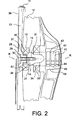
- figure 2 is a schematic view, in vertical section, of a detail of a tank-basket group of the washing machine in figure 1 ;
- figure 3 is a longitudinal section view of a portion of a support shaft of the tank-basket group according to an embodiment
- figure 4 is a front view of the support shaft in figure 3 ;
- figure 5 is a longitudinal section view of a connection portion of a pulley of the tank-basket group according to an embodiment
- figure 6 is a front view of the connection portion in figure 5 .
- the machine 1 comprises an outer housing 2, a washing tank 3 arranged inside the outer housing 2 and suitable for containing the lye, as well as a perforated clothes basket 4, arranged inside the washing tank 3 in a rotatable manner around a rotation axis R and defining a space 5, on the inside, for containing the clothes to be washed and/or dried.
- the clothes basket 4 can be made up of a back wall 6 through which the basket 4 is rotatably fixed to a support wall 12 of the tank 3, a front wall 7 defining a loading opening 9 through which it is possible to access the inside of the basket 4 and a side wall 8 that is perforated so as to allow the exchange of lye between the washing tank 3 and the inside of the basket 4 ( Figure 1 ).
- the clothes basket 4 is usually made up of a back wall 6 and a front wall 7, through which the basket is rotatably fixed to opposite support walls 12 of the tank 3, as well as a side wall 8 generally cylindrical and perforated so as to allow the exchange of lye between the washing tank and the inside of the basket, in which the side wall defines a loading opening (not illustrated) through which it is possible to access the inside of the basket.
- the machine 1 comprises a motor 10 and a drive 11, for example a belt drive, which transmits the rotary motion of the motor 10 to a pulley 13 arranged outside the washing tank 3 and connected so as to rotate as a unit with the clothes basket 4.
- a drive 11 for example a belt drive
- the tank 3 - basket 4 group also comprises a support shaft 14 that extends parallel to the rotation axis R and projects from the back wall 6 of the basket 4 towards the outside of the basket.
- the shaft 14 is rotatably received, through at least a first bearing 16, in a support seat 15 formed in the support wall 12 of the tank 3, and comprises a back end 17 facing outwards from the tank 3.
- the pulley 13 comprises a male fixing portion 18 extending parallel to the rotation axis R and projecting towards the tank 3 or, in other words, from outside of the tank towards the inside.
- the back end 17 of the shaft 14 forms a tubular wall 19 with a radially outer surface 20 (with reference to the rotation axis R) that forms a first bearing housing 21 that receives the first bearing and a radially inner surface 22 that defines a female pulley seat 23 formed inside the back end 17 of the shaft 14.
- the female pulley seat 23 receives the male fixing portion 18 of the pulley 13 axially in the thickness of the support wall 12 of the tank 3 ( Figure 2 ).
- the male fixing portion 18 of the pulley 13 extends axially in the area of the first bearing 16.
- the inner surface 22 of the pulley seat 23 can be profiled, for example notched through a plurality of longitudinal grooves 25 and even the male fixing portion 18 of the pulley 13 can form an outer surface 24 with a matching shape, for example notched and suitable for engaging the inner surface 22 through a shape coupling rotating as a unit around the rotation axis R.
- the profiling, for example notching 25 of the pulley seat 23 extends axially completely inside the axial extension of the first bearing 16.
- the male fixing portion 18 can also comprise an axial hole, preferably central, that receives a locking screw 27 and that opens into a back surface 28 opposite the tank 3, in a back cavity 29 having an axial with and depth such as to at least partially receive a nut or a head 30 of the locking screw 27.
- the back cavity 29 has an axial depth greater than 2/3 of the axial height of the head 30 or of the nut of the locking screw 27.
- the back cavity 29 completely receives the head 30 or the nut of the locking screw 27, so that the screw does not project axially out from the back cavity 29.
- the locking screw remains completely inside the axial bulk of the pulley and makes it possible to bring the tank-basket group, with the pulley, closer to the outer housing 2 of the washing machine 1.
- the locking screw 27 can be screwed in an internally threaded locking hole 31, formed in a bottom 32 of the pulley seat 23.
- the second bearing 33 fitted onto an annular surface 34 of the shaft 14 between the first bearing 16 and the back wall 6 of the basket 4 and, similarly to the first bearing 16, the second bearing 33 is also received in the support seat 15 of the tank 3, through an outer ring.
- the locking hole 31 extends axially up to inside the area of the second bearing 33.
- the shaft 14 can also comprise an outer shoulder 35 facing outwards from the tank 3 and preferably configured as a circumferential step that axially defines the first bearing housing 21 on a front side.
- the pulley 13 forms a clamping surface 36 that is preferably annular and substantially perpendicular to the rotation axis R, said clamping surface 36 facing towards the tank 3 and being suitable for engaging a back surface 37 of the first bearing 16 to clamp the first bearing 16 axially against the outer shoulder 36 of the shaft 14, when the male fixing portion 18 is locked in the female pulley seat 23.
- the first bearing 16 projects axially beyond the back end 17 of the shaft 14.
- the second bearing 33 preferably has an inner diameter that is greater with respect to the internal diameter of the first bearing 16, so that the outer shoulder 35 can be obtained through just the processing of the first bearing housing and without further reduction of diameter of the shaft at the annular surface 34.
- This configuration also makes it possible to have an easy assembly of the tank-basket group through the insertion of the shaft 14 from inside of the tank into the support seat 15 with the bearings 16, 33 already mounted.
- the axial depth D38 of the pulley seat 23 is greater than half of the axial distance D40 between a back edge 39 of the pulley 13 (meant as the furthest back surface or portion of the pulley) and its clamping surface 36 in contact with the first bearing 16.
- a frontal end 41 of the shaft 14 is anchored to the back wall 6 of the basket 4 so that the shaft 14 rotates with the basket 4.
- the front end 41 can comprise circumferential anti-extraction grooves 42 engaged by corresponding circumferential protuberances 43 of the back wall 6 and/or longitudinal anti-rotation grooves 44 engaged by corresponding longitudinal protuberances 45 of the back wall 6.
- the back wall 6 of the basket can comprise an anchoring body 46 and the front end 41 of the shaft is embedded in the anchoring body 46 during its formation through moulding.
Landscapes
- Engineering & Computer Science (AREA)
- Textile Engineering (AREA)
- Main Body Construction Of Washing Machines And Laundry Dryers (AREA)
Abstract
Description
- The present invention refers to a tank-basket group for a washing machine, dryer or washer dryer.
- Known washing machines comprise an outer housing, a washing tank arranged inside the outer housing and suitable for containing the lye, as well as a perforated clothes basket, arranged rotatably inside the washing tank and defining inside a space for containing the clothes to be washed. In front-loading washing machines and washes dryers, the clothes basket is usually made up of a back wall through which the basket is rotatably fixed inside the tank, a front wall defining a loading opening through which it is possible to access the inside of the basket and a side wall that is perforated so as to allow the exchange of lye between the washing rank and the inside of the basket.
- In top-loading washing machines, the clothes basket is usually made up of a back wall and a front wall, through which the basket is rotatably fixed inside the tank, as well as a generally cylindrical and perforated side wall to allow the exchange of lye between the washing tank and the inside of the basket, in which the side wall defines a loading opening through which it is possible to access the inside of the basket.
- In order to make the basket rotate inside the washing tank, known washing machines comprise a motor and a belt drive that transmits the rotary motion of the motor to a pulley arranged outside the washing tank and that is connected so as to rotate as a unit with the clothes basket.
- Thanks to the rotational movement of the basket, the clothes are agitated and rolled around in the lye and the lye itself is pulled upwards in rotation by the basket from which it falls on the clothes which are completely soaked and softened, so as to transfer the impurities to the washing and rinsing lye.
- However, in known washing machines and washer dryers, the rotary support of the clothes basket in the back wall of the washing tank, which must withstand high mechanical 1 stresses in particular during the centrifuging of the clothes, and the positioning and connection of the pulley in the same position are very bulky so that a part of the depth of the outer housing cannot be exploited to contain clothes to be washed and/or dried.
- The purpose of the present invention is therefore that of proposing a tank-basket group for washing machines, washer dryers or dryers having characteristics such as to reduce the bulk that cannot be used for containing clothes.
- Within the main purpose, a particular purpose of the invention is that of proposing a tank-basket group having an overall depth that is smaller for the same depth of the clothes basket.
- These and other purposes are achieved with a tank-basket group for washing machines, washer dryers or dryers, the tank - basket group comprising:
- a washing tank suitable for containing the lye and having a support wall,
- a clothes basket arranged inside the washing tank, the clothes basket having a back wall that is rotatably connected to the support wall of the washing tank,
- a driving pulley arranged outside the washing tank and connected so as to rotate together with the back wall of the clothes basket,
- a shaft projecting along a rotation axis from the back wall of the basket and rotatably received in a support seat formed in the support wall of the tank, said shaft having a back end facing outwards from the tank,
in which - the pulley comprises a male fixing portion projecting along a rotation axis towards the tank,
- the back end of the shaft forms a tubular wall with an outer surface that forms a first bearing housing that receives a first bearing and an inner surface defining a female pulley seat that receives the male fixing portion of the pulley axially in the thickness of the support wall of the tank.
- Thanks to the housing of the male fixing portion of the pulley in the thickness of the support wall of the tank, axial space is saved making it possible to increase the axial depth of the basket and therefore to increase the load of clothes for the same outer dimensions of the household appliance.
- In order to better understand the invention and to appreciate its advantages, hereafter, we shall describe some embodiments given as an example and not for limiting purposes, with reference to the attached figures, in which:
-
figure 1 is a schematic view, in vertical section, of a washing machine according to an embodiment of the invention; -
figure 2 is a schematic view, in vertical section, of a detail of a tank-basket group of the washing machine infigure 1 ; -
figure 3 is a longitudinal section view of a portion of a support shaft of the tank-basket group according to an embodiment; -
figure 4 is a front view of the support shaft infigure 3 ; -
figure 5 is a longitudinal section view of a connection portion of a pulley of the tank-basket group according to an embodiment; -
figure 6 is a front view of the connection portion infigure 5 . - With reference to the figures, a washing machine, washer dryer or dryer is wholly indicated with reference numeral The machine 1 comprises an
outer housing 2, awashing tank 3 arranged inside theouter housing 2 and suitable for containing the lye, as well as aperforated clothes basket 4, arranged inside thewashing tank 3 in a rotatable manner around a rotation axis R and defining aspace 5, on the inside, for containing the clothes to be washed and/or dried. Theclothes basket 4 can be made up of a back wall 6 through which thebasket 4 is rotatably fixed to asupport wall 12 of thetank 3, afront wall 7 defining a loading opening 9 through which it is possible to access the inside of thebasket 4 and a side wall 8 that is perforated so as to allow the exchange of lye between thewashing tank 3 and the inside of the basket 4 (Figure 1 ). - Alternatively, in top-loading washing machines, the
clothes basket 4 is usually made up of a back wall 6 and afront wall 7, through which the basket is rotatably fixed toopposite support walls 12 of thetank 3, as well as a side wall 8 generally cylindrical and perforated so as to allow the exchange of lye between the washing tank and the inside of the basket, in which the side wall defines a loading opening (not illustrated) through which it is possible to access the inside of the basket. - In order to make the
basket 4 rotate inside thewashing tank 3, the machine 1 comprises amotor 10 and adrive 11, for example a belt drive, which transmits the rotary motion of themotor 10 to apulley 13 arranged outside thewashing tank 3 and connected so as to rotate as a unit with theclothes basket 4. - The tank 3 -
basket 4 group also comprises asupport shaft 14 that extends parallel to the rotation axis R and projects from the back wall 6 of thebasket 4 towards the outside of the basket. Theshaft 14 is rotatably received, through at least a first bearing 16, in asupport seat 15 formed in thesupport wall 12 of thetank 3, and comprises aback end 17 facing outwards from thetank 3. - The
pulley 13 comprises amale fixing portion 18 extending parallel to the rotation axis R and projecting towards thetank 3 or, in other words, from outside of the tank towards the inside. Theback end 17 of theshaft 14 forms atubular wall 19 with a radially outer surface 20 (with reference to the rotation axis R) that forms a first bearinghousing 21 that receives the first bearing and a radiallyinner surface 22 that defines afemale pulley seat 23 formed inside theback end 17 of theshaft 14. - The
female pulley seat 23 receives themale fixing portion 18 of thepulley 13 axially in the thickness of thesupport wall 12 of the tank 3 (Figure 2 ). - Thanks to the housing of the male fixing portion of the pulley in the thickness of the support will of the tank, axial space is saved allowing the axial depth of the basket to be increased and therefore the clothes load is increased for the same outer dimensions of the household appliance.
- In accordance with an embodiment, the
male fixing portion 18 of thepulley 13 extends axially in the area of the first bearing 16. - The
inner surface 22 of thepulley seat 23 can be profiled, for example notched through a plurality oflongitudinal grooves 25 and even themale fixing portion 18 of thepulley 13 can form anouter surface 24 with a matching shape, for example notched and suitable for engaging theinner surface 22 through a shape coupling rotating as a unit around the rotation axis R. - In accordance with an embodiment, the profiling, for example notching 25 of the
pulley seat 23 extends axially completely inside the axial extension of the first bearing 16. - This advantageously makes it possible to use the same axial space both for the rotatable connection and the vertical support of the basket to the tank, as well as for the connection of the pulley so as to rotate as a unit with the clothes basket.
- The
male fixing portion 18 can also comprise an axial hole, preferably central, that receives alocking screw 27 and that opens into aback surface 28 opposite thetank 3, in aback cavity 29 having an axial with and depth such as to at least partially receive a nut or ahead 30 of thelocking screw 27. - In accordance with an embodiment, the
back cavity 29 has an axial depth greater than 2/3 of the axial height of thehead 30 or of the nut of thelocking screw 27. - Preferably, the
back cavity 29 completely receives thehead 30 or the nut of thelocking screw 27, so that the screw does not project axially out from theback cavity 29. - Thanks to this configuration, the locking screw remains completely inside the axial bulk of the pulley and makes it possible to bring the tank-basket group, with the pulley, closer to the
outer housing 2 of the washing machine 1. - The
locking screw 27 can be screwed in an internally threadedlocking hole 31, formed in abottom 32 of thepulley seat 23. - In accordance with an embodiment, it is foreseen for there to be a second bearing 33 fitted onto an
annular surface 34 of theshaft 14 between the first bearing 16 and the back wall 6 of thebasket 4 and, similarly to the first bearing 16, the second bearing 33 is also received in thesupport seat 15 of thetank 3, through an outer ring. Advantageously, thelocking hole 31 extends axially up to inside the area of the second bearing 33. - The
shaft 14 can also comprise anouter shoulder 35 facing outwards from thetank 3 and preferably configured as a circumferential step that axially defines the first bearinghousing 21 on a front side. On the other side, thepulley 13 forms aclamping surface 36 that is preferably annular and substantially perpendicular to the rotation axis R, saidclamping surface 36 facing towards thetank 3 and being suitable for engaging aback surface 37 of the first bearing 16 to clamp the first bearing 16 axially against theouter shoulder 36 of theshaft 14, when themale fixing portion 18 is locked in thefemale pulley seat 23. - In order to obtain a single support between the
clamping surface 36 and the first bearing 16 and in order to reduce the axial bulk of the pulley-shaft connection, the first bearing 16 projects axially beyond theback end 17 of theshaft 14. - The second bearing 33 preferably has an inner diameter that is greater with respect to the internal diameter of the first bearing 16, so that the
outer shoulder 35 can be obtained through just the processing of the first bearing housing and without further reduction of diameter of the shaft at theannular surface 34. This configuration also makes it possible to have an easy assembly of the tank-basket group through the insertion of theshaft 14 from inside of the tank into thesupport seat 15 with thebearings - In accordance with a preferred embodiment, the axial depth D38 of the
pulley seat 23 is greater than half of the axial distance D40 between aback edge 39 of the pulley 13 (meant as the furthest back surface or portion of the pulley) and itsclamping surface 36 in contact with the first bearing 16. - Even more preferably, the ratio between the axial depth D38 of the pulley seat and the aforementioned axial distance D40 is of between D38 / D40 = 0.75 to 1.25, obtaining an optimal exploitation of the available axial space, taking into account the vertical support requirements, the moments of cantilevered support of the basket, stress due to the centrifugal forces and the twisting coupling between the pulley and the basket.
- A
frontal end 41 of theshaft 14 is anchored to the back wall 6 of thebasket 4 so that theshaft 14 rotates with thebasket 4. In accordance with an embodiment, thefront end 41 can comprise circumferentialanti-extraction grooves 42 engaged by correspondingcircumferential protuberances 43 of the back wall 6 and/or longitudinalanti-rotation grooves 44 engaged by correspondinglongitudinal protuberances 45 of the back wall 6. For such a purpose, the back wall 6 of the basket can comprise ananchoring body 46 and thefront end 41 of the shaft is embedded in the anchoringbody 46 during its formation through moulding. - Further variants and/or additions are well within the capabilities of the man skilled in the art, without for this reason departing from the scope of protection defined in the attached claims.
Claims (15)
- A tank-basket group (3, 4, 13, 14) for a washing machine (1), washer dryer or dryer, the tank - basket group comprising:- a washing tank (3) suitable for containing the lye and having a support wall (12),- a clothes basket (4) arranged inside the washing tank (3), the clothes basket (4) having a back wall (6) that is rotatably connected to the support wall (12) of the washing tank (3),- a driving pulley (13) arranged outside the washing tank (3) and connected in a way such as to rotate with the back wall (6) of the clothes basket (4),- a shaft (14) parallel to the rotation axis (R) projecting from the back wall (6) of the basket (3) and rotatably received in a support seat (15) formed in the support wall (12) of the tank (3), said shaft (14) having a back end (17) facing outwards from the tank (3),characterised in that- the pulley (13) comprises a male fixing portion (18) extending parallel to the rotation axis (R) and projecting towards the tank (3),- the back end (17) of the shaft (14) forms a tubular wall (19) with an outer surface (20) that forms a first bearing housing (21) that receives a first bearing (16) and an inner surface (22) defining a female pulley seat (23) that receives the male fixing portion (18) of the pulley (13) axially in the thickness of the support wall (12) of the tank (3).
- Tank-basket group according to claim 1, wherein the male fixing portion (18) of the pulley (13) extends axially in the area of the first bearing (16).
- Tank-basket group according to any one of the previous claims, wherein the inner surface (22) of the pulley seat (23) is notched and the male fixing portion (18) forms an outer surface (24) that is notched and is suitable for engaging with the inner surface (22) through shape coupling rotating as a unit.
- Tank-basket group according to any one of the previous claims, wherein the notching (25) of the pulley seat (23) extends axially completely inside the axial extension of the first bearing (16).
- Tank-basket group according to any one of the previous claims, wherein the male fixing portion (18) comprises a hole (26) that receives a locking screw (27) and the pulley (13) forms, in a back surface (28) opposite the tank (3), a back cavity (29) for receiving a nut or a head (30) of the locking screw (27).
- Tank-basket group according to claim 5, wherein the back cavity (29) has an axial depth greater than 2/3 of the axial height of the head (30) or of the nut of the locking screw (27).
- Tank-basket group according to claim 5, wherein the back cavity (29) completely receives the head (30) or the nut of the locking screw (27), so that it does not axially protrude outside from the back cavity (29).
- Tank-basket group according to any one of the previous claims, wherein the shaft (14) comprises an internally threaded locking hole (31), said locking hole (31) being formed in a bottom (32) of the pulley seat (23) and being suitable for receiving a locking screw (27).
- Tank-basket group according to claim 8, comprising: a second bearing (33) fitted onto an annular surface (34) of the shaft between said first bearing (16) and the back wall (6) of the basket, wherein said locking hole (31) extends axially up to inside the area of the second bearing (33).
- Tank-basket group according to any one of the previous claims, wherein said shaft (14) comprises an outer shoulder (35) facing outwards from the tank (3) and axially defining the first bearing housing (21), wherein the pulley (13) forms an annular clamping surface (36) substantially perpendicular to the rotation axis (R) and facing towards the tank (3), said clamping surface (36) being suitable for engaging with a back surface (37) of the first bearing (16) to lock the first bearing (16) axially against the outer shoulder (35) of the shaft, when the male fixing portion (18) is locked in the female pulley seat (23).
- Tank-basket group according to any one of the previous claims, wherein said first bearing (16) projects axially beyond the back end (17) of the shaft (14).
- Tank-basket group according to any one of the previous claims, comprising a second bearing (33) fitted onto an annular surface (34) of the shaft (15) between said first bearing (16) and the back wall (6) of the basket (4), wherein said second bearing (33) has an internal diameter that is greater than the internal diameter of the first bearing (16).
- Tank-basket group according to any one of the previous claims, wherein an axial depth (D38) of the pulley seat (23) is greater than half of the axial distance (D40) between a back edge (39) of the pulley and its clamping surface (36) in contact with the first bearing (16), preferably the ratio (D38/D40) between the axial depth (D38) and the axial distance (D40) is of between 0.75 to 1.25.
- Tank-basket group according to any one of the previous claims, wherein said shaft (14) comprises a front end (41) anchored to the back wall (6) of the basket (4) so that the shaft rotates with the basket, said front end (41) comprising:- anti-extraction circumferential grooves (42) engaged by corresponding circumferential protuberances (43) of the back wall,- longitudinal anti-rotation grooves (44) engaged by corresponding longitudinal protuberances (45) of the back wall.
- Washing machine (1), washer dryer or dryer, comprising a tank basket group according to any one of the previous claims.
Priority Applications (2)
| Application Number | Priority Date | Filing Date | Title |
|---|---|---|---|
| ES10425264.8T ES2445142T3 (en) | 2010-07-30 | 2010-07-30 | Tank-basket group for a washing machine, a washer-dryer or a dryer |
| EP10425264.8A EP2412863B1 (en) | 2010-07-30 | 2010-07-30 | Tank-basket group for a washing machine, washer dryer or dryer |
Applications Claiming Priority (1)
| Application Number | Priority Date | Filing Date | Title |
|---|---|---|---|
| EP10425264.8A EP2412863B1 (en) | 2010-07-30 | 2010-07-30 | Tank-basket group for a washing machine, washer dryer or dryer |
Publications (2)
| Publication Number | Publication Date |
|---|---|
| EP2412863A1 true EP2412863A1 (en) | 2012-02-01 |
| EP2412863B1 EP2412863B1 (en) | 2013-11-06 |
Family
ID=43530997
Family Applications (1)
| Application Number | Title | Priority Date | Filing Date |
|---|---|---|---|
| EP10425264.8A Not-in-force EP2412863B1 (en) | 2010-07-30 | 2010-07-30 | Tank-basket group for a washing machine, washer dryer or dryer |
Country Status (2)
| Country | Link |
|---|---|
| EP (1) | EP2412863B1 (en) |
| ES (1) | ES2445142T3 (en) |
Citations (5)
| Publication number | Priority date | Publication date | Assignee | Title |
|---|---|---|---|---|
| GB1161214A (en) * | 1966-08-31 | 1969-08-13 | Philips Electronic Associated | Improvements in or relating to Domestic Washing Machines. |
| DE2410339A1 (en) * | 1973-03-07 | 1974-09-19 | Skf Kugellagerfabriken Gmbh | DRUM BEARING FOR WASHING MACHINES |
| FR2499112A1 (en) * | 1981-01-30 | 1982-08-06 | Thomson Brandt | Anti-friction bearing for washing machine drum - comprises compact, water-tight unit |
| EP1967636A1 (en) * | 2007-03-07 | 2008-09-10 | Electrolux Home Products Corporation N.V. | Household clothes washing machine with integrated drum spider |
| CN201236285Y (en) * | 2008-07-28 | 2009-05-13 | 南京乐金熊猫电器有限公司 | Water leakage proof apparatus of drum washing machine |
-
2010
- 2010-07-30 ES ES10425264.8T patent/ES2445142T3/en active Active
- 2010-07-30 EP EP10425264.8A patent/EP2412863B1/en not_active Not-in-force
Patent Citations (5)
| Publication number | Priority date | Publication date | Assignee | Title |
|---|---|---|---|---|
| GB1161214A (en) * | 1966-08-31 | 1969-08-13 | Philips Electronic Associated | Improvements in or relating to Domestic Washing Machines. |
| DE2410339A1 (en) * | 1973-03-07 | 1974-09-19 | Skf Kugellagerfabriken Gmbh | DRUM BEARING FOR WASHING MACHINES |
| FR2499112A1 (en) * | 1981-01-30 | 1982-08-06 | Thomson Brandt | Anti-friction bearing for washing machine drum - comprises compact, water-tight unit |
| EP1967636A1 (en) * | 2007-03-07 | 2008-09-10 | Electrolux Home Products Corporation N.V. | Household clothes washing machine with integrated drum spider |
| CN201236285Y (en) * | 2008-07-28 | 2009-05-13 | 南京乐金熊猫电器有限公司 | Water leakage proof apparatus of drum washing machine |
Also Published As
| Publication number | Publication date |
|---|---|
| EP2412863B1 (en) | 2013-11-06 |
| ES2445142T3 (en) | 2014-02-28 |
Similar Documents
| Publication | Publication Date | Title |
|---|---|---|
| US9284676B2 (en) | Drum type washing machine | |
| US20130276483A1 (en) | Washing machine | |
| CN101608389B (en) | Drum washing machine | |
| CN101994230B (en) | Washing machine, connection of inner tub of washing machine and balancer, and assembling method thereof | |
| KR101061127B1 (en) | Washing machine tub with inserted bearing housing | |
| CN107075773B (en) | drum washing machine | |
| CN108193435B (en) | Drum set washing machine and working method thereof | |
| KR20100045316A (en) | Washing machine | |
| KR200444489Y1 (en) | Sealing structure for drum washing machine, spider for drum washing machine and drum washing machine using same | |
| US8336341B2 (en) | Tub for a washing machine with a bearing housing | |
| US20160194801A1 (en) | Washing machine | |
| EP2412863B1 (en) | Tank-basket group for a washing machine, washer dryer or dryer | |
| CN112609393A (en) | Washing machine | |
| EP2270273A1 (en) | Washing machine | |
| US20200190719A1 (en) | Pulsator device for washing machine and washing machine including same | |
| KR20170040303A (en) | Drum washing machine | |
| KR20050006328A (en) | Drum Type Washer | |
| US20040103698A1 (en) | Drum assembly of washing machine | |
| CN114808371B (en) | Drum assembly and washing machine | |
| US11346035B2 (en) | Washing machine | |
| KR20080106477A (en) | washer | |
| EP4172398B1 (en) | Washing machine | |
| KR101730316B1 (en) | Top loading type washing machine | |
| KR20080040338A (en) | Drum washing machine | |
| JP7325013B2 (en) | washing machine |
Legal Events
| Date | Code | Title | Description |
|---|---|---|---|
| AK | Designated contracting states |
Kind code of ref document: A1 Designated state(s): AL AT BE BG CH CY CZ DE DK EE ES FI FR GB GR HR HU IE IS IT LI LT LU LV MC MK MT NL NO PL PT RO SE SI SK SM TR |
|
| AX | Request for extension of the european patent |
Extension state: BA ME RS |
|
| PUAI | Public reference made under article 153(3) epc to a published international application that has entered the european phase |
Free format text: ORIGINAL CODE: 0009012 |
|
| 17P | Request for examination filed |
Effective date: 20120327 |
|
| GRAP | Despatch of communication of intention to grant a patent |
Free format text: ORIGINAL CODE: EPIDOSNIGR1 |
|
| INTG | Intention to grant announced |
Effective date: 20130726 |
|
| GRAS | Grant fee paid |
Free format text: ORIGINAL CODE: EPIDOSNIGR3 |
|
| GRAA | (expected) grant |
Free format text: ORIGINAL CODE: 0009210 |
|
| AK | Designated contracting states |
Kind code of ref document: B1 Designated state(s): AL AT BE BG CH CY CZ DE DK EE ES FI FR GB GR HR HU IE IS IT LI LT LU LV MC MK MT NL NO PL PT RO SE SI SK SM TR |
|
| REG | Reference to a national code |
Ref country code: GB Ref legal event code: FG4D |
|
| REG | Reference to a national code |
Ref country code: CH Ref legal event code: EP |
|
| REG | Reference to a national code |
Ref country code: AT Ref legal event code: REF Ref document number: 639576 Country of ref document: AT Kind code of ref document: T Effective date: 20131215 |
|
| REG | Reference to a national code |
Ref country code: IE Ref legal event code: FG4D |
|
| REG | Reference to a national code |
Ref country code: DE Ref legal event code: R096 Ref document number: 602010011465 Country of ref document: DE Effective date: 20140109 |
|
| REG | Reference to a national code |
Ref country code: ES Ref legal event code: FG2A Ref document number: 2445142 Country of ref document: ES Kind code of ref document: T3 Effective date: 20140228 |
|
| REG | Reference to a national code |
Ref country code: NL Ref legal event code: VDEP Effective date: 20131106 |
|
| REG | Reference to a national code |
Ref country code: AT Ref legal event code: MK05 Ref document number: 639576 Country of ref document: AT Kind code of ref document: T Effective date: 20131106 |
|
| REG | Reference to a national code |
Ref country code: LT Ref legal event code: MG4D |
|
| PG25 | Lapsed in a contracting state [announced via postgrant information from national office to epo] |
Ref country code: NL Free format text: LAPSE BECAUSE OF FAILURE TO SUBMIT A TRANSLATION OF THE DESCRIPTION OR TO PAY THE FEE WITHIN THE PRESCRIBED TIME-LIMIT Effective date: 20131106 Ref country code: IS Free format text: LAPSE BECAUSE OF FAILURE TO SUBMIT A TRANSLATION OF THE DESCRIPTION OR TO PAY THE FEE WITHIN THE PRESCRIBED TIME-LIMIT Effective date: 20140306 Ref country code: HR Free format text: LAPSE BECAUSE OF FAILURE TO SUBMIT A TRANSLATION OF THE DESCRIPTION OR TO PAY THE FEE WITHIN THE PRESCRIBED TIME-LIMIT Effective date: 20131106 Ref country code: FI Free format text: LAPSE BECAUSE OF FAILURE TO SUBMIT A TRANSLATION OF THE DESCRIPTION OR TO PAY THE FEE WITHIN THE PRESCRIBED TIME-LIMIT Effective date: 20131106 Ref country code: SE Free format text: LAPSE BECAUSE OF FAILURE TO SUBMIT A TRANSLATION OF THE DESCRIPTION OR TO PAY THE FEE WITHIN THE PRESCRIBED TIME-LIMIT Effective date: 20131106 Ref country code: NO Free format text: LAPSE BECAUSE OF FAILURE TO SUBMIT A TRANSLATION OF THE DESCRIPTION OR TO PAY THE FEE WITHIN THE PRESCRIBED TIME-LIMIT Effective date: 20140206 Ref country code: LT Free format text: LAPSE BECAUSE OF FAILURE TO SUBMIT A TRANSLATION OF THE DESCRIPTION OR TO PAY THE FEE WITHIN THE PRESCRIBED TIME-LIMIT Effective date: 20131106 |
|
| PG25 | Lapsed in a contracting state [announced via postgrant information from national office to epo] |
Ref country code: AT Free format text: LAPSE BECAUSE OF FAILURE TO SUBMIT A TRANSLATION OF THE DESCRIPTION OR TO PAY THE FEE WITHIN THE PRESCRIBED TIME-LIMIT Effective date: 20131106 Ref country code: BE Free format text: LAPSE BECAUSE OF FAILURE TO SUBMIT A TRANSLATION OF THE DESCRIPTION OR TO PAY THE FEE WITHIN THE PRESCRIBED TIME-LIMIT Effective date: 20131106 Ref country code: LV Free format text: LAPSE BECAUSE OF FAILURE TO SUBMIT A TRANSLATION OF THE DESCRIPTION OR TO PAY THE FEE WITHIN THE PRESCRIBED TIME-LIMIT Effective date: 20131106 |
|
| PG25 | Lapsed in a contracting state [announced via postgrant information from national office to epo] |
Ref country code: PT Free format text: LAPSE BECAUSE OF FAILURE TO SUBMIT A TRANSLATION OF THE DESCRIPTION OR TO PAY THE FEE WITHIN THE PRESCRIBED TIME-LIMIT Effective date: 20140306 |
|
| PG25 | Lapsed in a contracting state [announced via postgrant information from national office to epo] |
Ref country code: EE Free format text: LAPSE BECAUSE OF FAILURE TO SUBMIT A TRANSLATION OF THE DESCRIPTION OR TO PAY THE FEE WITHIN THE PRESCRIBED TIME-LIMIT Effective date: 20131106 |
|
| REG | Reference to a national code |
Ref country code: DE Ref legal event code: R097 Ref document number: 602010011465 Country of ref document: DE |
|
| PG25 | Lapsed in a contracting state [announced via postgrant information from national office to epo] |
Ref country code: PL Free format text: LAPSE BECAUSE OF FAILURE TO SUBMIT A TRANSLATION OF THE DESCRIPTION OR TO PAY THE FEE WITHIN THE PRESCRIBED TIME-LIMIT Effective date: 20131106 Ref country code: SK Free format text: LAPSE BECAUSE OF FAILURE TO SUBMIT A TRANSLATION OF THE DESCRIPTION OR TO PAY THE FEE WITHIN THE PRESCRIBED TIME-LIMIT Effective date: 20131106 Ref country code: RO Free format text: LAPSE BECAUSE OF FAILURE TO SUBMIT A TRANSLATION OF THE DESCRIPTION OR TO PAY THE FEE WITHIN THE PRESCRIBED TIME-LIMIT Effective date: 20131106 Ref country code: CZ Free format text: LAPSE BECAUSE OF FAILURE TO SUBMIT A TRANSLATION OF THE DESCRIPTION OR TO PAY THE FEE WITHIN THE PRESCRIBED TIME-LIMIT Effective date: 20131106 |
|
| PLBE | No opposition filed within time limit |
Free format text: ORIGINAL CODE: 0009261 |
|
| STAA | Information on the status of an ep patent application or granted ep patent |
Free format text: STATUS: NO OPPOSITION FILED WITHIN TIME LIMIT |
|
| PG25 | Lapsed in a contracting state [announced via postgrant information from national office to epo] |
Ref country code: DK Free format text: LAPSE BECAUSE OF FAILURE TO SUBMIT A TRANSLATION OF THE DESCRIPTION OR TO PAY THE FEE WITHIN THE PRESCRIBED TIME-LIMIT Effective date: 20131106 |
|
| 26N | No opposition filed |
Effective date: 20140807 |
|
| REG | Reference to a national code |
Ref country code: DE Ref legal event code: R097 Ref document number: 602010011465 Country of ref document: DE Effective date: 20140807 |
|
| REG | Reference to a national code |
Ref country code: DE Ref legal event code: R119 Ref document number: 602010011465 Country of ref document: DE |
|
| PG25 | Lapsed in a contracting state [announced via postgrant information from national office to epo] |
Ref country code: LU Free format text: LAPSE BECAUSE OF FAILURE TO SUBMIT A TRANSLATION OF THE DESCRIPTION OR TO PAY THE FEE WITHIN THE PRESCRIBED TIME-LIMIT Effective date: 20140730 Ref country code: SI Free format text: LAPSE BECAUSE OF FAILURE TO SUBMIT A TRANSLATION OF THE DESCRIPTION OR TO PAY THE FEE WITHIN THE PRESCRIBED TIME-LIMIT Effective date: 20131106 |
|
| REG | Reference to a national code |
Ref country code: CH Ref legal event code: PL |
|
| GBPC | Gb: european patent ceased through non-payment of renewal fee |
Effective date: 20140730 |
|
| REG | Reference to a national code |
Ref country code: IE Ref legal event code: MM4A |
|
| REG | Reference to a national code |
Ref country code: DE Ref legal event code: R119 Ref document number: 602010011465 Country of ref document: DE Effective date: 20150203 |
|
| PG25 | Lapsed in a contracting state [announced via postgrant information from national office to epo] |
Ref country code: CH Free format text: LAPSE BECAUSE OF NON-PAYMENT OF DUE FEES Effective date: 20140731 Ref country code: DE Free format text: LAPSE BECAUSE OF NON-PAYMENT OF DUE FEES Effective date: 20150203 Ref country code: LI Free format text: LAPSE BECAUSE OF NON-PAYMENT OF DUE FEES Effective date: 20140731 |
|
| PG25 | Lapsed in a contracting state [announced via postgrant information from national office to epo] |
Ref country code: GB Free format text: LAPSE BECAUSE OF NON-PAYMENT OF DUE FEES Effective date: 20140730 |
|
| PG25 | Lapsed in a contracting state [announced via postgrant information from national office to epo] |
Ref country code: IE Free format text: LAPSE BECAUSE OF NON-PAYMENT OF DUE FEES Effective date: 20140730 |
|
| PG25 | Lapsed in a contracting state [announced via postgrant information from national office to epo] |
Ref country code: SM Free format text: LAPSE BECAUSE OF FAILURE TO SUBMIT A TRANSLATION OF THE DESCRIPTION OR TO PAY THE FEE WITHIN THE PRESCRIBED TIME-LIMIT Effective date: 20131106 Ref country code: MC Free format text: LAPSE BECAUSE OF FAILURE TO SUBMIT A TRANSLATION OF THE DESCRIPTION OR TO PAY THE FEE WITHIN THE PRESCRIBED TIME-LIMIT Effective date: 20131106 |
|
| PG25 | Lapsed in a contracting state [announced via postgrant information from national office to epo] |
Ref country code: MT Free format text: LAPSE BECAUSE OF FAILURE TO SUBMIT A TRANSLATION OF THE DESCRIPTION OR TO PAY THE FEE WITHIN THE PRESCRIBED TIME-LIMIT Effective date: 20131106 Ref country code: GR Free format text: LAPSE BECAUSE OF FAILURE TO SUBMIT A TRANSLATION OF THE DESCRIPTION OR TO PAY THE FEE WITHIN THE PRESCRIBED TIME-LIMIT Effective date: 20140207 Ref country code: BG Free format text: LAPSE BECAUSE OF FAILURE TO SUBMIT A TRANSLATION OF THE DESCRIPTION OR TO PAY THE FEE WITHIN THE PRESCRIBED TIME-LIMIT Effective date: 20131106 Ref country code: CY Free format text: LAPSE BECAUSE OF FAILURE TO SUBMIT A TRANSLATION OF THE DESCRIPTION OR TO PAY THE FEE WITHIN THE PRESCRIBED TIME-LIMIT Effective date: 20131106 |
|
| REG | Reference to a national code |
Ref country code: FR Ref legal event code: PLFP Year of fee payment: 7 |
|
| PG25 | Lapsed in a contracting state [announced via postgrant information from national office to epo] |
Ref country code: HU Free format text: LAPSE BECAUSE OF FAILURE TO SUBMIT A TRANSLATION OF THE DESCRIPTION OR TO PAY THE FEE WITHIN THE PRESCRIBED TIME-LIMIT; INVALID AB INITIO Effective date: 20100730 Ref country code: TR Free format text: LAPSE BECAUSE OF FAILURE TO SUBMIT A TRANSLATION OF THE DESCRIPTION OR TO PAY THE FEE WITHIN THE PRESCRIBED TIME-LIMIT Effective date: 20131106 |
|
| REG | Reference to a national code |
Ref country code: FR Ref legal event code: PLFP Year of fee payment: 8 |
|
| PG25 | Lapsed in a contracting state [announced via postgrant information from national office to epo] |
Ref country code: MK Free format text: LAPSE BECAUSE OF FAILURE TO SUBMIT A TRANSLATION OF THE DESCRIPTION OR TO PAY THE FEE WITHIN THE PRESCRIBED TIME-LIMIT Effective date: 20131106 |
|
| REG | Reference to a national code |
Ref country code: FR Ref legal event code: PLFP Year of fee payment: 9 |
|
| PG25 | Lapsed in a contracting state [announced via postgrant information from national office to epo] |
Ref country code: AL Free format text: LAPSE BECAUSE OF FAILURE TO SUBMIT A TRANSLATION OF THE DESCRIPTION OR TO PAY THE FEE WITHIN THE PRESCRIBED TIME-LIMIT Effective date: 20131106 |
|
| PGFP | Annual fee paid to national office [announced via postgrant information from national office to epo] |
Ref country code: IT Payment date: 20220726 Year of fee payment: 13 Ref country code: ES Payment date: 20220801 Year of fee payment: 13 |
|
| PGFP | Annual fee paid to national office [announced via postgrant information from national office to epo] |
Ref country code: FR Payment date: 20220726 Year of fee payment: 13 |
|
| PG25 | Lapsed in a contracting state [announced via postgrant information from national office to epo] |
Ref country code: FR Free format text: LAPSE BECAUSE OF NON-PAYMENT OF DUE FEES Effective date: 20230731 |
|
| PG25 | Lapsed in a contracting state [announced via postgrant information from national office to epo] |
Ref country code: IT Free format text: LAPSE BECAUSE OF NON-PAYMENT OF DUE FEES Effective date: 20230730 |
|
| REG | Reference to a national code |
Ref country code: ES Ref legal event code: FD2A Effective date: 20240904 |
|
| PG25 | Lapsed in a contracting state [announced via postgrant information from national office to epo] |
Ref country code: ES Free format text: LAPSE BECAUSE OF NON-PAYMENT OF DUE FEES Effective date: 20230731 |
|
| PG25 | Lapsed in a contracting state [announced via postgrant information from national office to epo] |
Ref country code: ES Free format text: LAPSE BECAUSE OF NON-PAYMENT OF DUE FEES Effective date: 20230731 |