EP2412624A1 - Cargo tank for liquefied gas carrier ship - Google Patents
Cargo tank for liquefied gas carrier ship Download PDFInfo
- Publication number
- EP2412624A1 EP2412624A1 EP11175494A EP11175494A EP2412624A1 EP 2412624 A1 EP2412624 A1 EP 2412624A1 EP 11175494 A EP11175494 A EP 11175494A EP 11175494 A EP11175494 A EP 11175494A EP 2412624 A1 EP2412624 A1 EP 2412624A1
- Authority
- EP
- European Patent Office
- Prior art keywords
- thermal insulating
- auxiliary
- wall
- bridge pad
- cargo tank
- Prior art date
- Legal status (The legal status is an assumption and is not a legal conclusion. Google has not performed a legal analysis and makes no representation as to the accuracy of the status listed.)
- Granted
Links
Images

Classifications
-
- B—PERFORMING OPERATIONS; TRANSPORTING
- B63—SHIPS OR OTHER WATERBORNE VESSELS; RELATED EQUIPMENT
- B63B—SHIPS OR OTHER WATERBORNE VESSELS; EQUIPMENT FOR SHIPPING
- B63B25/00—Load-accommodating arrangements, e.g. stowing, trimming; Vessels characterised thereby
- B63B25/02—Load-accommodating arrangements, e.g. stowing, trimming; Vessels characterised thereby for bulk goods
- B63B25/08—Load-accommodating arrangements, e.g. stowing, trimming; Vessels characterised thereby for bulk goods fluid
- B63B25/12—Load-accommodating arrangements, e.g. stowing, trimming; Vessels characterised thereby for bulk goods fluid closed
- B63B25/16—Load-accommodating arrangements, e.g. stowing, trimming; Vessels characterised thereby for bulk goods fluid closed heat-insulated
-
- B—PERFORMING OPERATIONS; TRANSPORTING
- B63—SHIPS OR OTHER WATERBORNE VESSELS; RELATED EQUIPMENT
- B63B—SHIPS OR OTHER WATERBORNE VESSELS; EQUIPMENT FOR SHIPPING
- B63B3/00—Hulls characterised by their structure or component parts
- B63B3/14—Hull parts
- B63B3/68—Panellings; Linings, e.g. for insulating purposes
-
- F—MECHANICAL ENGINEERING; LIGHTING; HEATING; WEAPONS; BLASTING
- F17—STORING OR DISTRIBUTING GASES OR LIQUIDS
- F17C—VESSELS FOR CONTAINING OR STORING COMPRESSED, LIQUEFIED OR SOLIDIFIED GASES; FIXED-CAPACITY GAS-HOLDERS; FILLING VESSELS WITH, OR DISCHARGING FROM VESSELS, COMPRESSED, LIQUEFIED, OR SOLIDIFIED GASES
- F17C3/00—Vessels not under pressure
- F17C3/02—Vessels not under pressure with provision for thermal insulation
- F17C3/04—Vessels not under pressure with provision for thermal insulation by insulating layers
Definitions
- the present invention relates to a cargo tank for liquefied gas carrier ship, and more particularly, to a cargo tank for liquefied gas carrier ship which includes a plurality of thermal insulating panels.
- Liquefied gas such as liquefied natural gas (LNG) is obtained by liquefying a gas that is in a vapor state at a room temperature at an extremely low temperature that is lower than a saturation temperature, and is carried by a conveying unit such as ship.
- LNG liquefied natural gas
- a cargo tank for receiving the liquefied gas is provided in the ship.
- the cargo tank has various types of thermal insulating structures in order to maintain the liquefied state of the liquefied gas at the extremely low temperature, for example, -163°C or less, from departure place where the liquefied gas is injected into the cargo tank to destination where the liquefied gas is unloaded from the cargo tank.
- the cargo tank includes a liquefied gas leakage prevention structure for preventing the liquefied gas from leaking out of the cargo tank.
- the cargo tank may be manufactured in various types, for example, a MOSS type of independence tank that is formed as a spherical metal structure or a membrane tank type formed to have a plurality of cell structures, according a shape and a structure of the cargo tank.
- a MOSS type of independence tank that is formed as a spherical metal structure or a membrane tank type formed to have a plurality of cell structures, according a shape and a structure of the cargo tank.
- the cargo tank manufactured as the membrane tank type includes a main wall formed of stainless steel for surrounding a receiving space that is formed in the cargo tank to receive the liquefied gas, a thermal insulating panel assembly surrounding the main wall, and an outer wall surrounding the thermal insulating panel assembly.
- the thermal insulating panel assembly is formed of a thermal insulating material such as polyurethane foams, and includes a plurality of first thermal insulating panels and a plurality of second thermal panels respectively disposed in two-layered structures, and auxiliary walls disposed between the first thermal insulating panels and the second thermal insulating panels and formed of a triplex material having a plurality of layers formed of, for example, aluminum and fiber glass.
- a thermal insulating material such as polyurethane foams
- the plurality of first thermal insulating panels and the plurality of second thermal insulating panels are disposed alternately with each other.
- bridge pad is disposed between the plurality of second thermal insulating panels for filling separate spaces between the second thermal insulating panels.
- auxiliary walls disposed between the plurality of first thermal insulating panels, the plurality of second thermal insulating panels, and the plurality of bridge pad are fixed on the panels or the pads via an attachment method.
- the plurality of first thermal insulating panels disposed in a first layer of the thermal panel assembly and the plurality of second thermal insulating panels and the bridge pad disposed in a second layer of the thermal panel assembly overlap each other to certain regions.
- the main wall and the thermal insulating panel assembly that are adjacent to the receiving space are exposed to the extremely low temperature, in a state where the liquefied gas is received in the receiving space of the cargo tank.
- the plurality of panels and the plurality of bridge pad forming the thermal insulating panel assembly are thermally contracted.
- stress caused by the thermal contraction of the panels and the bridge pad is applied on the auxiliary walls fixed between the plurality of panels and the plurality of bridge pad.
- the auxiliary walls may be broken by the concentrated stress, and thus, a sealing state of the liquefied gas may be damaged.
- the present invention provides a cargo tank for liquefied gas carrier ship which prevents auxiliary walls from being damaged due to stress caused by thermal contraction of a plurality of panels and a bridge pad included in a thermal insulating panel assembly.
- a cargo tank for a liquefied gas carrier ship comprising: a main wall surrounding a receiving space in which the liquefied gas is received; a panel assembly surrounding the main wall; and an outer wall surrounding the panel assembly, wherein the panel assembly comprises: a plurality of first thermal insulating panels arranged to be separate first distances from each other; a plurality of first auxiliary walls, first surfaces of which are fixed on the first thermal insulating panels, separate from each other; a plurality of second thermal insulating panels fixed on second surfaces of the first auxiliary walls and arranged with second distances; bridge pad disposed between the second thermal insulating panels and separate from the second thermal insulating panels; and a second auxiliary wall located between the bridge pad and the first auxiliary walls, having first surfaces fixed on the bridge pad, and second surfaces, a part of which are fixed on the first auxiliary walls, wherein between each of the first thermal insulating panel and each of the first auxiliary walls fixed on the first thermal insulating panel
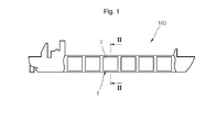
- FIG. 1 is a cross-sectional view of a liquefied gas carrier ship 100 according to an embodiment of the present invention
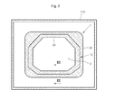
- FIG. 2 is a cross-sectional view of a cargo tank 1 taken along a line II-II of FIG. 1 .
- the liquefied gas carrier ship 100 is a ship for carrying liquefied gas that is liquefied at an extremely low temperature, for example, liquefied natural gas (LNG), and includes a cargo tank 1 for receiving the liquefied gas.
- LNG liquefied natural gas
- the cargo tank 1 may be manufactured in various types, for example, a MOSS type of independent tank, in which a part of the cargo tank that is formed as a spherical metal structure protrudes out of the ship, and a membrane tank type formed to have a membrane type cargo tank.
- a MOSS type of independent tank in which a part of the cargo tank that is formed as a spherical metal structure protrudes out of the ship
- a membrane tank type formed to have a membrane type cargo tank.
- the cargo tank 1 of the present embodiment is formed as the membrane tank type.
- the cargo tank 1 is disposed on the liquefied gas carrier ship 100 in a state of being surrounded by an outer wall 110 of the ship 100.
- a ballast tank may be disposed between the cargo tank 1 and the outer wall 110 of the ship for adjusting buoyancy of the ship 100.
- the cargo tank 1 includes a receiving space 2 formed in the cargo tank 1 for receiving the liquefied gas, a main wall 20 surrounding the receiving space 2, a panel assembly 10 surrounding the main wall 20, and an outer wall 30 surrounding the panel assembly 10.
- the receiving space 2 is sealed by the main wall 20 so as to prevent the liquefied gas received in the receiving space 2 from leaking out of the receiving space 2.
- the receiving space 2 is partitioned into a plurality of spaces in the liquefied gas carrier ship 100. Therefore, even if one of the partitions of the receiving space 2 is damaged, sealing states of the other partitions of the receiving space 2 may be maintained.
- the main wall 20 surrounds the receiving space 2 and may be formed of, for example, a stainless steel material having a high rigidity. In addition, the main wall 20 performs a primary blocking for preventing the liquefied gas from leaking out of the receiving space 2.
- the panel assembly 10 thermally insulates the receiving space 2 from an outer portion of the cargo tank 1 such that a temperature of the liquefied gas received in the receiving space 2 may be maintained at the extremely low temperature.
- auxiliary walls 14 and 15 shown in FIG. 3 ) that are continuously succeeded are disposed in the panel assembly 10, and the auxiliary walls 14 and 15 perform a secondary blocking for preventing the liquefied gas from leaking out of the receiving space 2.
- the outer wall 30 forms an outer appearance of the cargo tank 1, and surrounds the panel assembly 10.
- the outer wall 30 is formed of a metal material of high rigidity to prevent the main wall 20 and the panel assembly 10 from being damaged and the shape of the cargo tank 1 from deforming due to external shocks.
- the panel assembly 10 of the present embodiment includes a plurality of panels, a plurality of pads, and a plurality of walls for thermally insulating the receiving space 2 and for preventing the liquefied gas received in the receiving space 2 from leaking out of the receiving space 2.
- FIG. 3 is a cross-sectional view of the panel assembly 10 taken along a line III-III of FIG. 2
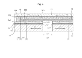
- FIG. 4 is an expanded view of part IV shown in FIG. 3 .
- the panel assembly 10 of the present embodiment is located between the main wall 20 surrounding the receiving space 2 and the outer wall 30 forming the outer appearance of the cargo tank 1.
- an attaching member 31 is disposed on a side of the panel assembly 10, which is adjacent to the outer wall 30, so that the panel assembly 10 may be fixed on the outer wall 30 in a state of being separated a predetermined gap from the outer wall 30.
- the attaching member 31 such as Mastic is disposed in the space between the outer wall 30 and the panel assembly 10, and the attaching member 31 is hardened so as to firmly fix the outer wall 30 and the panel assembly 10 to each other.
- the main wall 20 may include a plurality of metal plates, and the plurality of metal plates are fixed to each other by welding.
- the panel assembly10 includes a plurality of first thermal insulating panels 11, a plurality of second thermal insulating panels 12, a plurality of bridge pad 13, a plurality of first auxiliary walls 14, and a second auxiliary wall 15.
- the components in the panel assembly 10 are fixed to each other by a plurality of fixing regions 161, 162, 163, and 164 on which an adhesive is applied.
- the first thermal insulating panels 11, the second thermal insulating panels 12, and the bridge pad 13 are arranged in a plurality of layered structures in the panel assembly, and may be formed of a thermal insulating member such as rigid polyurethane foam (RPUF).
- RPUF rigid polyurethane foam
- the first thermal insulating panels 11 are arranged in a first layer that is adjacent to the outer wall 30 to be separate a first distance d1 from each other.
- a filling material such as glass wool may be filled in the first distance d1.
- the second thermal insulating panels 12 are arranged in a second layer that is adjacent to the main wall 20 to be separate a second distance d2 that is greater than the first distance d1 from each other.
- the bridge pad 13 is arranged in the second layer, like the second thermal insulating panels 12, between the second thermal insulating panels 12 that are separate from each other.
- the bridge pad 13 is arranged to be separate a third distance d3 from the adjacent second thermal insulating panels 12.
- Some parts of the first thermal insulating panels 11 disposed in the first layer and some parts of the bridge pad 13 disposed in the second layer may overlap each other.
- the auxiliary walls 14 and 15 are disposed between the first layer, in which the first thermal insulating panels 11 are arranged, and the second layer, in which the second thermal insulating panels 12 and the bridge pad 13 are arranged, for additionally maintaining the sealing state of the receiving space 2.
- the auxiliary walls 14 and 15 may be formed of a triplex material which is fabricated by adhering fiber glasses on both surfaces of an aluminum thin plate.
- the auxiliary walls 14 and 15 include a plurality of first auxiliary walls 14 and a plurality of second auxiliary walls 15.
- the first thermal insulating panel 11 is fixed on a surface(first surface) in each of the first auxiliary walls 14, and the second thermal insulating panel 12 is fixed on the other surface(second surface) in each of the first auxiliary walls 14.
- each of the second thermal insulating walls 15 is disposed between the bridge pad 13 and the first thermal insulating panels 11 overlapping the bridge pad 13.
- the bridge pad 13 is fixed on a surface of the second auxiliary wall 15, and a part of the other surface in the second auxiliary wall 15 is fixed on a part of the surface of the first auxiliary wall 14.
- first auxiliary walls 14 and the second auxiliary walls 15 are arranged successively and fixed to each other so as to perform the secondary blocking of the receiving space 2.
- the fixing regions 161, 162, 163, and 164 for fixing the panels, the bridge pad, and the auxiliary walls to each other include first fixing regions 161, second fixing regions 162, third fixing regions 163, and fourth fixing regions 164.
- Each of the first fixing regions 161 is disposed between each of the first thermal insulating panels 11 and each of the first auxiliary walls 14, and the adhesive is applied onto the first fixing region 161 to fix the first thermal insulating panel 11 and the first auxiliary wall 14 to each other.
- each of the second fixing regions 162 is disposed between each of the first auxiliary walls 14 and the second auxiliary wall 15, and the adhesive is applied onto the second fixing region 162 to fix the first and second auxiliary walls 14 and 15 to each other.
- each of the third fixing regions 163 is disposed between the second auxiliary wall 15 and the bridge pad 13, and the adhesive is applied onto the third fixing region 163 to fix the second auxiliary wall 15 and the bridge pad 13 to each other.
- the adhesive is applied to the third fixing region 163 to a thickness that is greater than thicknesses of the first auxiliary wall 14 and the second auxiliary wall 15.
- the fourth fixing region 164 is succeeded to the third fixing region 163, and the first auxiliary wall 14 is located at a side of the fourth fixing region 164 and the bridge pad 13 is disposed at the other side of the fourth fixing region 164. That is, the fourth fixing region 164 is disposed along with boundaries of the second fixing region 162, the third fixing region 163, and the second auxiliary wall 15.
- the second auxiliary wall 15 is surrounded by the adhesive applied on the second, third, and fourth fixing regions 162, 163, and 164.
- some of the adhesive applied on the third fixing region 163 may be injected into the fourth fixing region 164 by the force applied from the bridge pad 13 toward the first thermal insulating panel 11.
- contraction forces are applied to the first thermal insulating panels 11 arranged in the first layer and the bridge pad 13 arranged in the second layer and overlapping the first thermal insulating panels 11 in opposite directions, that is, in a direction P1 and a direction P2. Therefore, stress is generated on the first auxiliary walls 14 and the second auxiliary wall 15 disposed between the first thermal insulating panels 11 and the bridge pad 13 due to the contraction forces applied in the opposite directions.
- the concentration of stress is maximized on a portion where a pair of first and second auxiliary walls 14 and 15 that are adjacent to each other, that is, the first distance d1.
- the concentration of the stress is maximized and the stress exceeds a threshold stress of one of the first and second auxiliary walls 14 and 15, the first or second auxiliary wall 14 or 15 is damaged and the sealing state of the receiving space 2 is damaged.
- first stress dispersion regions 171 on which the adhesive is not applied are formed between the first thermal insulating panels 11 and the first auxiliary walls 14 fixed on the first thermal insulating walls 11.
- the adhesive is not applied on the first stress dispersion region 171, and the first thermal insulating panel 11 and the first auxiliary wall 14 are not fixed to each other on the portion where the first stress dispersion region 171 is formed.
- the first stress dispersion region 171 is located on a circumferential portion 141 on a surface of the first auxiliary wall 14, and the first fixing region 161 for fixing the first thermal insulating panel 11 and the first auxiliary wall 14 to each other is located on an inner portion 142 of the first auxiliary wall 14, which is classified based on the first stress dispersion region 171
- a first stress dispersion distance d4 that is greater than the first distance d1 is formed by one pair of first stress dispersion regions 171 formed between one pair of first thermal insulating panels 11 and the first auxiliary walls 14 that are separate the first distance d1 from each other.
- the stress is concentrated on the distance between the circumferences of a pair of first auxiliary walls 14, that is, the first distance d1.
- the stress is dispersed to the distance between a pair of first fixing regions 161, that is, the first stress dispersion distance d4, and thereby preventing the stress that is generated due to the thermal contraction of the first thermal insulating panel 11 and the bridge pad 13 from excessively concentrating on a certain region.
- first fixing distance d5 and a second fixing distance d6 are formed adjacent to the first stress dispersion distance d4 in a direction apart from the first stress dispersion distance d4.
- first fixing distance d5 means a portion where the first thermal insulating panel 11, the first fixing region 161, the first auxiliary wall 14, the second fixing region 162, the second auxiliary wall 15, the third fixing region 163, and the bridge pad 13 overlap each other.
- second fixing distance d6 means a portion where the first thermal insulating panel 11, the first fixing region 161, the first auxiliary wall 14, the fourth fixing region 164, and the bridge pad 13 overlap each other.
- a part of the first fixing region 161 that is disposed between each of the first thermal insulating panels 11 and the first auxiliary wall 14 fixed on the first thermal insulating panel 11 may overlap a part of the second fixing region 162 that is disposed between each of the first auxiliary walls 14 and the second auxiliary wall 15 fixed on the first auxiliary wall 14.
- the stress applied between the first and second auxiliary walls 14 and 15 may be dispersed to the portion where the first and second fixing regions 161 and 162 overlap each other.
- some parts of the first fixing region 161 and the second fixing region 162 overlap each other, and thus, the fixed adhesion between the first thermal insulating panel 11, the first auxiliary wall 14, and the second auxiliary wall 15 performed by the first and second fixing regions 161 and 162 may be firmly performed, and strength may be increased.
- the first auxiliary wall 14 has an area corresponding to that of the first thermal insulating panel 11, and the second auxiliary wall 15 has an area that is smaller than that of the bridge pad 13.
- a part of the surface of the bridge pad 13, on which a surface of the second auxiliary wall 15 is fixed corresponds to the second auxiliary wall 15 and the other part of the surface of the bridge pad 13 corresponds to the first auxiliary wall 14.
- an additional fixed element is not formed between the first auxiliary wall 14 and the surface of the bridge pad 13, which directly faces the first auxiliary wall 14, and instead, a second stress dispersion region 172 having a second stress dispersion distance d7 is formed.
- the second stress dispersion region 172 is disposed along with an outer circumference of the fourth fixing region 164.
- the stress generated due to the first thermal insulating panel 11 and the bridge pad 13 which are contracted in opposite directions to each other may not be transferred to each other on the portion where the second stress dispersion region 172 is formed.
- the panel assembly 10 comprises one bridge pad 13 and one second auxiliary wall.
- the panel assembly 10 comprises a plurality of bridge pad and a plurality of second auxiliary walls.
- the stress caused by the contractions of the first thermal insulating panel and the bridge pad and applied between the first and second auxiliary walls is dispersed by the stress dispersion region, and thus, the damages of the auxiliary walls due to the excessive concentration of the stress may be prevented.
Landscapes
- Engineering & Computer Science (AREA)
- Mechanical Engineering (AREA)
- Chemical & Material Sciences (AREA)
- Combustion & Propulsion (AREA)
- Ocean & Marine Engineering (AREA)
- Physics & Mathematics (AREA)
- Thermal Sciences (AREA)
- General Engineering & Computer Science (AREA)
- Filling Or Discharging Of Gas Storage Vessels (AREA)
Abstract
Description
- This application claims the benefit of Korean Patent Application No.
10-2010-0074389, filed on July 30th, 2010 - The present invention relates to a cargo tank for liquefied gas carrier ship, and more particularly, to a cargo tank for liquefied gas carrier ship which includes a plurality of thermal insulating panels.
- Liquefied gas such as liquefied natural gas (LNG) is obtained by liquefying a gas that is in a vapor state at a room temperature at an extremely low temperature that is lower than a saturation temperature, and is carried by a conveying unit such as ship.
- In addition, a cargo tank for receiving the liquefied gas is provided in the ship.
- The cargo tank has various types of thermal insulating structures in order to maintain the liquefied state of the liquefied gas at the extremely low temperature, for example, -163°C or less, from departure place where the liquefied gas is injected into the cargo tank to destination where the liquefied gas is unloaded from the cargo tank. In addition, the cargo tank includes a liquefied gas leakage prevention structure for preventing the liquefied gas from leaking out of the cargo tank.
- The cargo tank may be manufactured in various types, for example, a MOSS type of independence tank that is formed as a spherical metal structure or a membrane tank type formed to have a plurality of cell structures, according a shape and a structure of the cargo tank.
- In particular, the cargo tank manufactured as the membrane tank type includes a main wall formed of stainless steel for surrounding a receiving space that is formed in the cargo tank to receive the liquefied gas, a thermal insulating panel assembly surrounding the main wall, and an outer wall surrounding the thermal insulating panel assembly.
- In addition, the thermal insulating panel assembly is formed of a thermal insulating material such as polyurethane foams, and includes a plurality of first thermal insulating panels and a plurality of second thermal panels respectively disposed in two-layered structures, and auxiliary walls disposed between the first thermal insulating panels and the second thermal insulating panels and formed of a triplex material having a plurality of layers formed of, for example, aluminum and fiber glass.
- Here, the plurality of first thermal insulating panels and the plurality of second thermal insulating panels are disposed alternately with each other. In addition, bridge pad is disposed between the plurality of second thermal insulating panels for filling separate spaces between the second thermal insulating panels.
- In addition, the auxiliary walls disposed between the plurality of first thermal insulating panels, the plurality of second thermal insulating panels, and the plurality of bridge pad are fixed on the panels or the pads via an attachment method.
- Here, the plurality of first thermal insulating panels disposed in a first layer of the thermal panel assembly and the plurality of second thermal insulating panels and the bridge pad disposed in a second layer of the thermal panel assembly overlap each other to certain regions.
- On the other hand, the main wall and the thermal insulating panel assembly that are adjacent to the receiving space are exposed to the extremely low temperature, in a state where the liquefied gas is received in the receiving space of the cargo tank.
- Therefore, the plurality of panels and the plurality of bridge pad forming the thermal insulating panel assembly are thermally contracted. Here, when the plurality of panels and the plurality of bridge pad are contracted in a state of overlapping each other to a predetermined degree, stress caused by the thermal contraction of the panels and the bridge pad is applied on the auxiliary walls fixed between the plurality of panels and the plurality of bridge pad.
- In addition, since the stress is concentrated on boundaries of the panels and the bridge pad, the auxiliary walls may be broken by the concentrated stress, and thus, a sealing state of the liquefied gas may be damaged.
- The present invention provides a cargo tank for liquefied gas carrier ship which prevents auxiliary walls from being damaged due to stress caused by thermal contraction of a plurality of panels and a bridge pad included in a thermal insulating panel assembly.
- According to an aspect of the present invention, there is provided a cargo tank for a liquefied gas carrier ship, the cargo tank comprising: a main wall surrounding a receiving space in which the liquefied gas is received; a panel assembly surrounding the main wall; and an outer wall surrounding the panel assembly, wherein the panel assembly comprises: a plurality of first thermal insulating panels arranged to be separate first distances from each other; a plurality of first auxiliary walls, first surfaces of which are fixed on the first thermal insulating panels, separate from each other; a plurality of second thermal insulating panels fixed on second surfaces of the first auxiliary walls and arranged with second distances; bridge pad disposed between the second thermal insulating panels and separate from the second thermal insulating panels; and a second auxiliary wall located between the bridge pad and the first auxiliary walls, having first surfaces fixed on the bridge pad, and second surfaces, a part of which are fixed on the first auxiliary walls, wherein between each of the first thermal insulating panel and each of the first auxiliary walls fixed on the first thermal insulating panel, a first fixing region on which an adhesive is applied to fix the first thermal insulating panel and the first auxiliary wall to each other, and a first stress dispersion region on which the adhesive is not applied for preventing the first auxiliary wall or the second auxiliary wall from being damaged due to thermal expansions or contractions of the first thermal insulating panels and the bridge pad.
- The above and other features and advantages of the present invention will become more apparent by describing in detail exemplary embodiments thereof with reference to the attached drawings in which:
-
FIG. 1 is a (cross-sectional view) of a liquefied gas carrier ship according to an embodiment of the present invention; -
FIG. 2 is a cross-sectional view of a cargo tank taken along a line II-II ofFIG. 1 ; -
FIG. 3 is a cross-sectional view of the cargo tank taken along a line III-III ofFIG. 2 ; and -
FIG. 4 is an expanded view of part IV shown inFIG. 3 . - Hereinafter, embodiments of the present invention will be described in detail with reference to accompanying drawings.
-
FIG. 1 is a cross-sectional view of a liquefiedgas carrier ship 100 according to an embodiment of the present invention, andFIG. 2 is a cross-sectional view of acargo tank 1 taken along a line II-II ofFIG. 1 . - Referring to
FIGS. 1 and2 , the liquefiedgas carrier ship 100 according to the present embodiment is a ship for carrying liquefied gas that is liquefied at an extremely low temperature, for example, liquefied natural gas (LNG), and includes acargo tank 1 for receiving the liquefied gas. - The
cargo tank 1 may be manufactured in various types, for example, a MOSS type of independent tank, in which a part of the cargo tank that is formed as a spherical metal structure protrudes out of the ship, and a membrane tank type formed to have a membrane type cargo tank. - The
cargo tank 1 of the present embodiment is formed as the membrane tank type. - The
cargo tank 1 is disposed on the liquefiedgas carrier ship 100 in a state of being surrounded by anouter wall 110 of theship 100. In addition, a ballast tank may be disposed between thecargo tank 1 and theouter wall 110 of the ship for adjusting buoyancy of theship 100. - The
cargo tank 1 includes areceiving space 2 formed in thecargo tank 1 for receiving the liquefied gas, amain wall 20 surrounding thereceiving space 2, apanel assembly 10 surrounding themain wall 20, and anouter wall 30 surrounding thepanel assembly 10. - The
receiving space 2 is sealed by themain wall 20 so as to prevent the liquefied gas received in thereceiving space 2 from leaking out of thereceiving space 2. In addition, thereceiving space 2 is partitioned into a plurality of spaces in the liquefiedgas carrier ship 100. Therefore, even if one of the partitions of thereceiving space 2 is damaged, sealing states of the other partitions of thereceiving space 2 may be maintained. - The
main wall 20 surrounds thereceiving space 2 and may be formed of, for example, a stainless steel material having a high rigidity. In addition, themain wall 20 performs a primary blocking for preventing the liquefied gas from leaking out of thereceiving space 2. - The
panel assembly 10 thermally insulates thereceiving space 2 from an outer portion of thecargo tank 1 such that a temperature of the liquefied gas received in thereceiving space 2 may be maintained at the extremely low temperature. In addition,auxiliary walls 14 and 15 (shown inFIG. 3 ) that are continuously succeeded are disposed in thepanel assembly 10, and theauxiliary walls receiving space 2. - The
outer wall 30 forms an outer appearance of thecargo tank 1, and surrounds thepanel assembly 10. In addition, theouter wall 30 is formed of a metal material of high rigidity to prevent themain wall 20 and thepanel assembly 10 from being damaged and the shape of thecargo tank 1 from deforming due to external shocks. - On the other hand, the
panel assembly 10 of the present embodiment includes a plurality of panels, a plurality of pads, and a plurality of walls for thermally insulating thereceiving space 2 and for preventing the liquefied gas received in thereceiving space 2 from leaking out of thereceiving space 2. - Hereinafter, structures of the
panel assembly 10 according to the present embodiment will be described in more detail. -
FIG. 3 is a cross-sectional view of thepanel assembly 10 taken along a line III-III ofFIG. 2 , andFIG. 4 is an expanded view of part IV shown inFIG. 3 . - Referring to
FIGS. 3 and4 , thepanel assembly 10 of the present embodiment is located between themain wall 20 surrounding thereceiving space 2 and theouter wall 30 forming the outer appearance of thecargo tank 1. - Here, an attaching
member 31 is disposed on a side of thepanel assembly 10, which is adjacent to theouter wall 30, so that thepanel assembly 10 may be fixed on theouter wall 30 in a state of being separated a predetermined gap from theouter wall 30. - In more detail, in a state where a side of a coupling member such as a stud bolt (not shown) is fixed on the
outer wall 30, the other side of the coupling member is inserted into a hole (not shown) formed in a firstthermal insulating panel 11 of thepanel assembly 10 so that theouter wall 30 and thepanel assembly 10 may be fixed to each other in a state of being separated from each other. Here, the attachingmember 31 such as Mastic is disposed in the space between theouter wall 30 and thepanel assembly 10, and the attachingmember 31 is hardened so as to firmly fix theouter wall 30 and thepanel assembly 10 to each other. - In addition, the
main wall 20 may include a plurality of metal plates, and the plurality of metal plates are fixed to each other by welding. - On the other hand, the panel assembly10 includes a plurality of first
thermal insulating panels 11, a plurality of second thermalinsulating panels 12, a plurality ofbridge pad 13, a plurality of firstauxiliary walls 14, and a secondauxiliary wall 15. In addition, the components in thepanel assembly 10 are fixed to each other by a plurality offixing regions - The first
thermal insulating panels 11, the second thermalinsulating panels 12, and thebridge pad 13 are arranged in a plurality of layered structures in the panel assembly, and may be formed of a thermal insulating member such as rigid polyurethane foam (RPUF). - The first
thermal insulating panels 11 are arranged in a first layer that is adjacent to theouter wall 30 to be separate a first distance d1 from each other. Here, a filling material such as glass wool may be filled in the first distance d1. - The second
thermal insulating panels 12 are arranged in a second layer that is adjacent to themain wall 20 to be separate a second distance d2 that is greater than the first distance d1 from each other. - In addition, the
bridge pad 13 is arranged in the second layer, like the secondthermal insulating panels 12, between the second thermalinsulating panels 12 that are separate from each other. Here, thebridge pad 13 is arranged to be separate a third distance d3 from the adjacent secondthermal insulating panels 12. - Some parts of the first thermal insulating
panels 11 disposed in the first layer and some parts of thebridge pad 13 disposed in the second layer may overlap each other. - On the other hand, the
auxiliary walls panels 11 are arranged, and the second layer, in which the second thermal insulatingpanels 12 and thebridge pad 13 are arranged, for additionally maintaining the sealing state of the receivingspace 2. - The
auxiliary walls - The
auxiliary walls auxiliary walls 14 and a plurality of secondauxiliary walls 15. - The first thermal insulating
panel 11 is fixed on a surface(first surface) in each of the firstauxiliary walls 14, and the second thermal insulatingpanel 12 is fixed on the other surface(second surface) in each of the firstauxiliary walls 14. - In addition, each of the second thermal insulating
walls 15 is disposed between thebridge pad 13 and the first thermal insulatingpanels 11 overlapping thebridge pad 13. Thebridge pad 13 is fixed on a surface of the secondauxiliary wall 15, and a part of the other surface in the secondauxiliary wall 15 is fixed on a part of the surface of the firstauxiliary wall 14. - That is, the first
auxiliary walls 14 and the secondauxiliary walls 15 are arranged successively and fixed to each other so as to perform the secondary blocking of the receivingspace 2. - The fixing
regions regions 161, second fixingregions 162, third fixingregions 163, and fourth fixingregions 164. - Each of the
first fixing regions 161 is disposed between each of the first thermal insulatingpanels 11 and each of the firstauxiliary walls 14, and the adhesive is applied onto thefirst fixing region 161 to fix the first thermal insulatingpanel 11 and the firstauxiliary wall 14 to each other. - In addition, each of the
second fixing regions 162 is disposed between each of the firstauxiliary walls 14 and the secondauxiliary wall 15, and the adhesive is applied onto thesecond fixing region 162 to fix the first and secondauxiliary walls - Likewise, each of the
third fixing regions 163 is disposed between the secondauxiliary wall 15 and thebridge pad 13, and the adhesive is applied onto thethird fixing region 163 to fix the secondauxiliary wall 15 and thebridge pad 13 to each other. - As an example, the adhesive is applied to the
third fixing region 163 to a thickness that is greater than thicknesses of the firstauxiliary wall 14 and the secondauxiliary wall 15. - Therefore, during installing the
panel assembly 10 of the present embodiment in thecargo tank 1, when an installation height of thebridge pad 13 is higher than that of the secondauxiliary wall 15, thebridge pad 13 are pushed toward the firstauxiliary walls 14 and the adhesive disposed on thethird fixing regions 163 is compressed so that the installation height of thebridge pad 13 may be adjusted to the level of the secondauxiliary wall 15. - On the other hand, the
fourth fixing region 164 is succeeded to thethird fixing region 163, and the firstauxiliary wall 14 is located at a side of thefourth fixing region 164 and thebridge pad 13 is disposed at the other side of thefourth fixing region 164. That is, thefourth fixing region 164 is disposed along with boundaries of thesecond fixing region 162, thethird fixing region 163, and the secondauxiliary wall 15. - Therefore, the second
auxiliary wall 15 is surrounded by the adhesive applied on the second, third, and fourth fixingregions - In addition, some of the adhesive applied on the
third fixing region 163 may be injected into thefourth fixing region 164 by the force applied from thebridge pad 13 toward the first thermal insulatingpanel 11. - On the other hand, in a state where the thermal insulating panels or the bridge pad and the auxiliary walls are fixedly adhered to each other, when the liquefied gas at the extremely low temperature is received in the receiving
space 2, the thermal insulating panels and the bridge pad are thermally contracted due to the extremely low temperature. - Here, contraction forces are applied to the first thermal insulating
panels 11 arranged in the first layer and thebridge pad 13 arranged in the second layer and overlapping the first thermal insulatingpanels 11 in opposite directions, that is, in a direction P1 and a direction P2. Therefore, stress is generated on the firstauxiliary walls 14 and the secondauxiliary wall 15 disposed between the first thermal insulatingpanels 11 and thebridge pad 13 due to the contraction forces applied in the opposite directions. - On the other hand, when the stress is applied to the first and second
auxiliary walls auxiliary walls second fixing region 162 and entire portion of the surface of the firstauxiliary wall 14 is completely fixed on the first thermal insulatingpanel 11, the concentration of stress is maximized on a portion where a pair of first and secondauxiliary walls - If the concentration of the stress is maximized and the stress exceeds a threshold stress of one of the first and second
auxiliary walls auxiliary wall space 2 is damaged. - Therefore, in the
panel assembly 10 of thecargo tank 1 according to the present embodiment, firststress dispersion regions 171 on which the adhesive is not applied are formed between the first thermal insulatingpanels 11 and the firstauxiliary walls 14 fixed on the first thermal insulatingwalls 11. - The adhesive is not applied on the first
stress dispersion region 171, and the first thermal insulatingpanel 11 and the firstauxiliary wall 14 are not fixed to each other on the portion where the firststress dispersion region 171 is formed. - Here, the first
stress dispersion region 171 is located on acircumferential portion 141 on a surface of the firstauxiliary wall 14, and thefirst fixing region 161 for fixing the first thermal insulatingpanel 11 and the firstauxiliary wall 14 to each other is located on aninner portion 142 of the firstauxiliary wall 14, which is classified based on the firststress dispersion region 171 - In addition, a first stress dispersion distance d4 that is greater than the first distance d1 is formed by one pair of first
stress dispersion regions 171 formed between one pair of first thermal insulatingpanels 11 and the firstauxiliary walls 14 that are separate the first distance d1 from each other. - That is, when the first
stress dispersion region 171 is not formed, the stress is concentrated on the distance between the circumferences of a pair of firstauxiliary walls 14, that is, the first distance d1. - However, as in the present embodiment, when the first
stress dispersion region 171 is formed, the stress is dispersed to the distance between a pair of first fixingregions 161, that is, the first stress dispersion distance d4, and thereby preventing the stress that is generated due to the thermal contraction of the first thermal insulatingpanel 11 and thebridge pad 13 from excessively concentrating on a certain region. - In addition, a first fixing distance d5 and a second fixing distance d6 are formed adjacent to the first stress dispersion distance d4 in a direction apart from the first stress dispersion distance d4. Here, the first fixing distance d5 means a portion where the first thermal insulating
panel 11, thefirst fixing region 161, the firstauxiliary wall 14, thesecond fixing region 162, the secondauxiliary wall 15, thethird fixing region 163, and thebridge pad 13 overlap each other. In addition, the second fixing distance d6 means a portion where the first thermal insulatingpanel 11, thefirst fixing region 161, the firstauxiliary wall 14, thefourth fixing region 164, and thebridge pad 13 overlap each other. - On the other hand, a part of the
first fixing region 161 that is disposed between each of the first thermal insulatingpanels 11 and the firstauxiliary wall 14 fixed on the first thermal insulatingpanel 11 may overlap a part of thesecond fixing region 162 that is disposed between each of the firstauxiliary walls 14 and the secondauxiliary wall 15 fixed on the firstauxiliary wall 14. - Therefore, the stress applied between the first and second
auxiliary walls regions first fixing region 161 and thesecond fixing region 162 overlap each other, and thus, the fixed adhesion between the first thermal insulatingpanel 11, the firstauxiliary wall 14, and the secondauxiliary wall 15 performed by the first and second fixingregions - On the other hand, the first
auxiliary wall 14 has an area corresponding to that of the first thermal insulatingpanel 11, and the secondauxiliary wall 15 has an area that is smaller than that of thebridge pad 13. - Therefore, a part of the surface of the
bridge pad 13, on which a surface of the secondauxiliary wall 15 is fixed, corresponds to the secondauxiliary wall 15 and the other part of the surface of thebridge pad 13 corresponds to the firstauxiliary wall 14. In addition, an additional fixed element is not formed between the firstauxiliary wall 14 and the surface of thebridge pad 13, which directly faces the firstauxiliary wall 14, and instead, a secondstress dispersion region 172 having a second stress dispersion distance d7 is formed. Here, the secondstress dispersion region 172 is disposed along with an outer circumference of thefourth fixing region 164. - That is, the stress generated due to the first thermal insulating
panel 11 and thebridge pad 13 which are contracted in opposite directions to each other may not be transferred to each other on the portion where the secondstress dispersion region 172 is formed. - According to the embodiments of the present invention referred in
Fig. 3 and4 , thepanel assembly 10 comprises onebridge pad 13 and one second auxiliary wall. However, it is available that thepanel assembly 10 comprises a plurality of bridge pad and a plurality of second auxiliary walls. - According to the embodiments of the present invention, the stress caused by the contractions of the first thermal insulating panel and the bridge pad and applied between the first and second auxiliary walls is dispersed by the stress dispersion region, and thus, the damages of the auxiliary walls due to the excessive concentration of the stress may be prevented.
- While the present invention has been particularly shown and described with reference to exemplary embodiments thereof, it will be understood by those of ordinary skill in the art that various changes in form and details may be made therein without departing from the spirit and scope of the present invention as defined by the following claims.
Claims (4)
- A cargo tank (1) for a liquefied gas carrier ship, the cargo tank (1) comprising:a main wall (20) surrounding a receiving space (2) in which the liquefied gas is received;a panel assembly (10) surrounding the main wall (20); andan outer wall (30) surrounding the panel assembly (10),wherein the panel assembly (10) comprises:a plurality of first thermal insulating panels (11) arranged to be separate first distances from each other;a plurality of first auxiliary walls (14), first surfaces of which are fixed on the first thermal insulating panels (11), separate from each other;a plurality of second thermal insulating panels (12) fixed on second surfaces of the first auxiliary walls (14) and arranged with second distances, which are greater than the first distances;bridge pad (13) disposed between the second thermal insulating panels (12) and separate from the second thermal insulating panels (12); anda second auxiliary wall (15) located between the bridge pad (13) and the first auxiliary walls (14), having first surfaces fixed on the bridge pad (13), and second surfaces, a part of which are fixed on the first auxiliary walls (14),wherein between each of the first thermal insulating panel (11) and each of the first auxiliary walls (14) fixed on the first thermal insulating panel (11), a first fixing region (161) on which an adhesive is applied to fix the first thermal insulating panel (11) and the first auxiliary wall (14) to each other, and a first stress dispersion region (171) on which the adhesive is not applied for preventing the first auxiliary wall (14) or the second auxiliary wall (15) from being damaged due to thermal expansions or contractions of the first thermal insulating panels (11) and the bridge pad (13).
- The cargo tank of claim 1, wherein the first stress dispersion region (171) is located on a circumferential portion (141) of the first surface in the first auxiliary wall (14).
- The cargo tank of claim 1 or 2, wherein a second fixing region (162) is disposed between each of the first auxiliary walls (14) and second auxiliary wall (15), and some parts of the first and second fixing regions overlap each other.
- The cargo tank according to any of the preceding claims, wherein a second stress dispersion region (172) which does not overlap the first stress dispersion region (171) is formed between each of the first auxiliary walls (14) and each of the bridge pad (13), for preventing the first auxiliary wall (14) or the second auxiliary wall (15) from being damaged due to thermal expansions or contractions of the first thermal insulating panels (14) and the bridge pad (13).
Applications Claiming Priority (1)
| Application Number | Priority Date | Filing Date | Title |
|---|---|---|---|
| KR1020100074389A KR101195605B1 (en) | 2010-07-30 | 2010-07-30 | Cargo for liquefied gas carrier ship |
Publications (2)
| Publication Number | Publication Date |
|---|---|
| EP2412624A1 true EP2412624A1 (en) | 2012-02-01 |
| EP2412624B1 EP2412624B1 (en) | 2013-10-02 |
Family
ID=44898251
Family Applications (1)
| Application Number | Title | Priority Date | Filing Date |
|---|---|---|---|
| EP11175494.1A Active EP2412624B1 (en) | 2010-07-30 | 2011-07-27 | Cargo tank for liquefied gas carrier ship |
Country Status (5)
| Country | Link |
|---|---|
| US (1) | US9016222B2 (en) |
| EP (1) | EP2412624B1 (en) |
| KR (1) | KR101195605B1 (en) |
| CN (1) | CN103153776B (en) |
| WO (1) | WO2012015158A2 (en) |
Cited By (2)
| Publication number | Priority date | Publication date | Assignee | Title |
|---|---|---|---|---|
| WO2014120080A1 (en) | 2013-01-29 | 2014-08-07 | Keppel Offshore & Marine Technology Centre Pte Ltd | Lng carrier construction method |
| FR3001945A1 (en) * | 2013-02-14 | 2014-08-15 | Gaztransp Et Technigaz | WATERPROOF AND THERMALLY INSULATING WALL FOR FLUID STORAGE TANK |
Families Citing this family (9)
| Publication number | Priority date | Publication date | Assignee | Title |
|---|---|---|---|---|
| FR3007498B1 (en) * | 2013-06-25 | 2017-03-31 | Gaztransport Et Technigaz | VACUUM INSULATING BLOCK |
| KR101599354B1 (en) * | 2014-03-31 | 2016-03-15 | 삼성중공업 주식회사 | Cargo and barrier structure of the same |
| JP6620315B2 (en) * | 2014-08-21 | 2019-12-18 | パナソニックIpマネジメント株式会社 | Insulated container |
| CN105523309B (en) * | 2014-09-29 | 2018-09-25 | 江南造船(集团)有限责任公司 | A kind of insulation system of Type B independent liquid cargo tank on liquefied gas carrier |
| CN105711736B (en) * | 2014-12-03 | 2017-10-27 | 江南造船(集团)有限责任公司 | The installation method of A type independent liquid cargo tanks dome insulation |
| KR101751838B1 (en) * | 2015-08-21 | 2017-07-19 | 대우조선해양 주식회사 | Insulation structure of liquefied natural gas cargo tank without anchor strip, cargo tank having the structure, and liquefied natural gas carrier |
| USRE50076E1 (en) * | 2015-12-30 | 2024-08-13 | Hyundai Heavy Industries Co., Ltd. | Liquefied gas carrier |
| KR102158648B1 (en) * | 2018-12-20 | 2020-09-23 | 대우조선해양 주식회사 | Insulation wall securing device for lng storage tank |
| FR3101390B1 (en) * | 2019-09-27 | 2021-09-03 | Gaztransport Et Technigaz | Sealed and thermally insulating tank |
Citations (5)
| Publication number | Priority date | Publication date | Assignee | Title |
|---|---|---|---|---|
| FR2781556A1 (en) * | 1998-07-24 | 2000-01-28 | Gaz Transport & Technigaz | Ships tank for liquid methane gas transport comprizes polymer and glass fiber sealing block and plate layers joined by deformable polymer and foil sandwich band. |
| DE102007056635A1 (en) * | 2006-11-30 | 2008-06-05 | Gaztransport Et Technigaz | Insulating block sticking method for liquid gas tanker ship, involves pressing insulating block against inner body until polymerization of adhesive, and applying adhesive beads on lower side of panel of block along parallel sinuous lines |
| WO2009154427A2 (en) * | 2008-06-19 | 2009-12-23 | 삼성중공업 주식회사 | Insulation structure of lng carrier cargo tank and construction method thereof |
| KR20090132514A (en) * | 2008-06-20 | 2009-12-30 | 삼성중공업 주식회사 | Corner panel of LNG cargo hold |
| KR20100074389A (en) | 2008-12-24 | 2010-07-02 | 농업협동조합중앙회 | Method for preparing rice yoghurt having the maximal content of rice ingredient, and the product obtained therefrom |
Family Cites Families (11)
| Publication number | Priority date | Publication date | Assignee | Title |
|---|---|---|---|---|
| US3929247A (en) * | 1973-07-11 | 1975-12-30 | Kaiser Aluminium Chem Corp | Cryogenic tank |
| FR2691520B1 (en) * | 1992-05-20 | 1994-09-02 | Technigaz Ste Nle | Prefabricated structure for forming watertight and thermally insulating walls for containment of a fluid at very low temperature. |
| FR2724623B1 (en) * | 1994-09-20 | 1997-01-10 | Gaztransport Et Technigaz | IMPROVED WATERPROOF AND THERMALLY INSULATING TANK INTEGRATED INTO A CARRIER STRUCTURE |
| CN100453402C (en) * | 2004-12-08 | 2009-01-21 | 韩国Gas公社 | Liquefied natural gas storage tank and manufacturing method thereof |
| KR100644217B1 (en) * | 2006-04-20 | 2006-11-10 | 한국가스공사 | LNG storage tank with improved insulation structure and its manufacturing method |
| KR100760482B1 (en) * | 2006-07-12 | 2007-09-20 | 한국과학기술원 | Insulation barrier joint structure and method of liquefied natural gas carrier |
| FR2911576B1 (en) * | 2007-01-23 | 2009-03-06 | Alstom Sa | METHOD FOR PRODUCING AN INSULATING WALL AND SEALING A TANK |
| KR100853178B1 (en) * | 2007-02-22 | 2008-08-20 | 삼성중공업 주식회사 | Gas leak prevention structure of insulation panel |
| CN101688640B (en) * | 2007-05-29 | 2011-06-08 | 现代重工业株式会社 | Liquefied natural gas storage tank insulation system with welded secondary walls and method of construction |
| KR101007697B1 (en) * | 2008-05-30 | 2011-01-13 | 삼성중공업 주식회사 | Second Barrier Crimping Device for Cargo Inside of LNG Carrier |
| JP5222061B2 (en) * | 2008-08-23 | 2013-06-26 | 川崎重工業株式会社 | Structure of joints provided between multiple thermal insulation panels arranged on the outer wall of a cryogenic tank |
-
2010
- 2010-07-30 KR KR1020100074389A patent/KR101195605B1/en active Active
-
2011
- 2011-05-19 WO PCT/KR2011/003674 patent/WO2012015158A2/en not_active Ceased
- 2011-05-19 CN CN201180037391.9A patent/CN103153776B/en active Active
- 2011-07-27 EP EP11175494.1A patent/EP2412624B1/en active Active
-
2013
- 2013-01-30 US US13/754,280 patent/US9016222B2/en active Active
Patent Citations (5)
| Publication number | Priority date | Publication date | Assignee | Title |
|---|---|---|---|---|
| FR2781556A1 (en) * | 1998-07-24 | 2000-01-28 | Gaz Transport & Technigaz | Ships tank for liquid methane gas transport comprizes polymer and glass fiber sealing block and plate layers joined by deformable polymer and foil sandwich band. |
| DE102007056635A1 (en) * | 2006-11-30 | 2008-06-05 | Gaztransport Et Technigaz | Insulating block sticking method for liquid gas tanker ship, involves pressing insulating block against inner body until polymerization of adhesive, and applying adhesive beads on lower side of panel of block along parallel sinuous lines |
| WO2009154427A2 (en) * | 2008-06-19 | 2009-12-23 | 삼성중공업 주식회사 | Insulation structure of lng carrier cargo tank and construction method thereof |
| KR20090132514A (en) * | 2008-06-20 | 2009-12-30 | 삼성중공업 주식회사 | Corner panel of LNG cargo hold |
| KR20100074389A (en) | 2008-12-24 | 2010-07-02 | 농업협동조합중앙회 | Method for preparing rice yoghurt having the maximal content of rice ingredient, and the product obtained therefrom |
Cited By (7)
| Publication number | Priority date | Publication date | Assignee | Title |
|---|---|---|---|---|
| WO2014120080A1 (en) | 2013-01-29 | 2014-08-07 | Keppel Offshore & Marine Technology Centre Pte Ltd | Lng carrier construction method |
| US10668996B2 (en) | 2013-01-29 | 2020-06-02 | Keppel Offshore & Marine Technology Centre Pte Ltd | LNG carrier construction method |
| FR3001945A1 (en) * | 2013-02-14 | 2014-08-15 | Gaztransp Et Technigaz | WATERPROOF AND THERMALLY INSULATING WALL FOR FLUID STORAGE TANK |
| WO2014125186A1 (en) * | 2013-02-14 | 2014-08-21 | Gaztransport Et Technigaz | Sealed and thermally insulating wall for a tank for storing fluid |
| CN104955722A (en) * | 2013-02-14 | 2015-09-30 | 气体运输技术公司 | Sealed and thermally insulating wall for a tank for storing fluid |
| RU2631746C2 (en) * | 2013-02-14 | 2017-09-26 | Газтранспорт Э Технигаз | Hermeticizing thermal insulating wall of the tank for storage of the fluid medium |
| US10876687B2 (en) | 2013-02-14 | 2020-12-29 | Gaztransport Et Technigaz | Sealed and thermally insulating wall for a tank for storing fluid |
Also Published As
| Publication number | Publication date |
|---|---|
| KR20120012305A (en) | 2012-02-09 |
| US9016222B2 (en) | 2015-04-28 |
| EP2412624B1 (en) | 2013-10-02 |
| WO2012015158A2 (en) | 2012-02-02 |
| CN103153776A (en) | 2013-06-12 |
| KR101195605B1 (en) | 2012-10-29 |
| CN103153776B (en) | 2016-07-06 |
| WO2012015158A3 (en) | 2012-04-12 |
| US20130206053A1 (en) | 2013-08-15 |
Similar Documents
| Publication | Publication Date | Title |
|---|---|---|
| EP2412624B1 (en) | Cargo tank for liquefied gas carrier ship | |
| KR102389246B1 (en) | Corner structure of sealed and insulated tank and assembly method thereof | |
| JP6479221B2 (en) | Sealed heat insulation tank having a secondary sealed membrane provided with a corner arrangement with a corrugated metal sheet | |
| US10458597B2 (en) | Insulation panel for corner area of LNG cargo containment system | |
| EP2306065B1 (en) | Insulation structure of lng carrier cargo tank and construction method thereof | |
| KR102188368B1 (en) | Corner structure of a sealed and thermally insulating tank for storing a fluid | |
| KR101751838B1 (en) | Insulation structure of liquefied natural gas cargo tank without anchor strip, cargo tank having the structure, and liquefied natural gas carrier | |
| US20150354756A1 (en) | Sealed and thermally insulating wall for a tank for storing fluid | |
| KR101505798B1 (en) | Base plate, and cargo tank including the same | |
| JP5894677B2 (en) | Pump tower installation structure of liquefied natural gas storage tank and manufacturing method thereof | |
| KR102387173B1 (en) | Insulation structure of 90 degree corner in liquefied gas cargo tank, and cargo tank having the insulation structure | |
| KR20170071623A (en) | Cross stacked insulation panel installation structure of independent type liquefied gas storage tank | |
| KR102255154B1 (en) | Insulation structure and liquefied gas storage tank having the same | |
| KR101422520B1 (en) | Insulation structure for cargo hold of LNG carrier | |
| CN116324260B (en) | Wall, tank, transfer system, ship and method for loading and unloading thereof | |
| KR101523906B1 (en) | Connection structure between base support and insulation barrier of cargo tank | |
| US12270512B2 (en) | Corner structure and liquefied gas storage tank having same | |
| KR101571425B1 (en) | Base support used for tank | |
| KR101588661B1 (en) | Cargo and reinforcing member used in the same | |
| KR101422515B1 (en) | Insulation panel of cargo and manufacturing method using the same | |
| KR20120010603A (en) | Cargo hold of liquefied gas transport ship and assembly method thereof | |
| KR101422517B1 (en) | Cargo for liquefied gas carrier ship and manufacturing method thereof | |
| KR20160072291A (en) | Cargo for liquefied gas | |
| KR102681151B1 (en) | Cargo barrier structure | |
| KR101399888B1 (en) | Cargo barrier structure |
Legal Events
| Date | Code | Title | Description |
|---|---|---|---|
| 17P | Request for examination filed |
Effective date: 20110727 |
|
| AK | Designated contracting states |
Kind code of ref document: A1 Designated state(s): AL AT BE BG CH CY CZ DE DK EE ES FI FR GB GR HR HU IE IS IT LI LT LU LV MC MK MT NL NO PL PT RO RS SE SI SK SM TR |
|
| AX | Request for extension of the european patent |
Extension state: BA ME |
|
| PUAI | Public reference made under article 153(3) epc to a published international application that has entered the european phase |
Free format text: ORIGINAL CODE: 0009012 |
|
| GRAP | Despatch of communication of intention to grant a patent |
Free format text: ORIGINAL CODE: EPIDOSNIGR1 |
|
| INTG | Intention to grant announced |
Effective date: 20130426 |
|
| GRAS | Grant fee paid |
Free format text: ORIGINAL CODE: EPIDOSNIGR3 |
|
| GRAA | (expected) grant |
Free format text: ORIGINAL CODE: 0009210 |
|
| AK | Designated contracting states |
Kind code of ref document: B1 Designated state(s): AL AT BE BG CH CY CZ DE DK EE ES FI FR GB GR HR HU IE IS IT LI LT LU LV MC MK MT NL NO PL PT RO RS SE SI SK SM TR |
|
| REG | Reference to a national code |
Ref country code: GB Ref legal event code: FG4D |
|
| REG | Reference to a national code |
Ref country code: CH Ref legal event code: EP Ref country code: AT Ref legal event code: REF Ref document number: 634459 Country of ref document: AT Kind code of ref document: T Effective date: 20131015 |
|
| REG | Reference to a national code |
Ref country code: IE Ref legal event code: FG4D |
|
| REG | Reference to a national code |
Ref country code: DE Ref legal event code: R096 Ref document number: 602011003237 Country of ref document: DE Effective date: 20131128 |
|
| REG | Reference to a national code |
Ref country code: AT Ref legal event code: MK05 Ref document number: 634459 Country of ref document: AT Kind code of ref document: T Effective date: 20131002 |
|
| REG | Reference to a national code |
Ref country code: NL Ref legal event code: VDEP Effective date: 20131002 |
|
| PG25 | Lapsed in a contracting state [announced via postgrant information from national office to epo] |
Ref country code: SI Free format text: LAPSE BECAUSE OF FAILURE TO SUBMIT A TRANSLATION OF THE DESCRIPTION OR TO PAY THE FEE WITHIN THE PRESCRIBED TIME-LIMIT Effective date: 20131002 |
|
| REG | Reference to a national code |
Ref country code: LT Ref legal event code: MG4D |
|
| PG25 | Lapsed in a contracting state [announced via postgrant information from national office to epo] |
Ref country code: SE Free format text: LAPSE BECAUSE OF FAILURE TO SUBMIT A TRANSLATION OF THE DESCRIPTION OR TO PAY THE FEE WITHIN THE PRESCRIBED TIME-LIMIT Effective date: 20131002 Ref country code: NL Free format text: LAPSE BECAUSE OF FAILURE TO SUBMIT A TRANSLATION OF THE DESCRIPTION OR TO PAY THE FEE WITHIN THE PRESCRIBED TIME-LIMIT Effective date: 20131002 Ref country code: BE Free format text: LAPSE BECAUSE OF FAILURE TO SUBMIT A TRANSLATION OF THE DESCRIPTION OR TO PAY THE FEE WITHIN THE PRESCRIBED TIME-LIMIT Effective date: 20131002 Ref country code: NO Free format text: LAPSE BECAUSE OF FAILURE TO SUBMIT A TRANSLATION OF THE DESCRIPTION OR TO PAY THE FEE WITHIN THE PRESCRIBED TIME-LIMIT Effective date: 20140102 Ref country code: IS Free format text: LAPSE BECAUSE OF FAILURE TO SUBMIT A TRANSLATION OF THE DESCRIPTION OR TO PAY THE FEE WITHIN THE PRESCRIBED TIME-LIMIT Effective date: 20140202 Ref country code: LT Free format text: LAPSE BECAUSE OF FAILURE TO SUBMIT A TRANSLATION OF THE DESCRIPTION OR TO PAY THE FEE WITHIN THE PRESCRIBED TIME-LIMIT Effective date: 20131002 Ref country code: FI Free format text: LAPSE BECAUSE OF FAILURE TO SUBMIT A TRANSLATION OF THE DESCRIPTION OR TO PAY THE FEE WITHIN THE PRESCRIBED TIME-LIMIT Effective date: 20131002 Ref country code: CZ Free format text: LAPSE BECAUSE OF FAILURE TO SUBMIT A TRANSLATION OF THE DESCRIPTION OR TO PAY THE FEE WITHIN THE PRESCRIBED TIME-LIMIT Effective date: 20131002 Ref country code: HR Free format text: LAPSE BECAUSE OF FAILURE TO SUBMIT A TRANSLATION OF THE DESCRIPTION OR TO PAY THE FEE WITHIN THE PRESCRIBED TIME-LIMIT Effective date: 20131002 |
|
| PG25 | Lapsed in a contracting state [announced via postgrant information from national office to epo] |
Ref country code: RS Free format text: LAPSE BECAUSE OF FAILURE TO SUBMIT A TRANSLATION OF THE DESCRIPTION OR TO PAY THE FEE WITHIN THE PRESCRIBED TIME-LIMIT Effective date: 20131002 Ref country code: AT Free format text: LAPSE BECAUSE OF FAILURE TO SUBMIT A TRANSLATION OF THE DESCRIPTION OR TO PAY THE FEE WITHIN THE PRESCRIBED TIME-LIMIT Effective date: 20131002 Ref country code: LV Free format text: LAPSE BECAUSE OF FAILURE TO SUBMIT A TRANSLATION OF THE DESCRIPTION OR TO PAY THE FEE WITHIN THE PRESCRIBED TIME-LIMIT Effective date: 20131002 Ref country code: ES Free format text: LAPSE BECAUSE OF FAILURE TO SUBMIT A TRANSLATION OF THE DESCRIPTION OR TO PAY THE FEE WITHIN THE PRESCRIBED TIME-LIMIT Effective date: 20131002 Ref country code: PL Free format text: LAPSE BECAUSE OF FAILURE TO SUBMIT A TRANSLATION OF THE DESCRIPTION OR TO PAY THE FEE WITHIN THE PRESCRIBED TIME-LIMIT Effective date: 20131002 Ref country code: CY Free format text: LAPSE BECAUSE OF FAILURE TO SUBMIT A TRANSLATION OF THE DESCRIPTION OR TO PAY THE FEE WITHIN THE PRESCRIBED TIME-LIMIT Effective date: 20131002 |
|
| PG25 | Lapsed in a contracting state [announced via postgrant information from national office to epo] |
Ref country code: PT Free format text: LAPSE BECAUSE OF FAILURE TO SUBMIT A TRANSLATION OF THE DESCRIPTION OR TO PAY THE FEE WITHIN THE PRESCRIBED TIME-LIMIT Effective date: 20140203 |
|
| REG | Reference to a national code |
Ref country code: DE Ref legal event code: R097 Ref document number: 602011003237 Country of ref document: DE |
|
| PG25 | Lapsed in a contracting state [announced via postgrant information from national office to epo] |
Ref country code: EE Free format text: LAPSE BECAUSE OF FAILURE TO SUBMIT A TRANSLATION OF THE DESCRIPTION OR TO PAY THE FEE WITHIN THE PRESCRIBED TIME-LIMIT Effective date: 20131002 |
|
| PLBE | No opposition filed within time limit |
Free format text: ORIGINAL CODE: 0009261 |
|
| STAA | Information on the status of an ep patent application or granted ep patent |
Free format text: STATUS: NO OPPOSITION FILED WITHIN TIME LIMIT |
|
| PG25 | Lapsed in a contracting state [announced via postgrant information from national office to epo] |
Ref country code: RO Free format text: LAPSE BECAUSE OF FAILURE TO SUBMIT A TRANSLATION OF THE DESCRIPTION OR TO PAY THE FEE WITHIN THE PRESCRIBED TIME-LIMIT Effective date: 20131002 Ref country code: IT Free format text: LAPSE BECAUSE OF FAILURE TO SUBMIT A TRANSLATION OF THE DESCRIPTION OR TO PAY THE FEE WITHIN THE PRESCRIBED TIME-LIMIT Effective date: 20131002 Ref country code: SK Free format text: LAPSE BECAUSE OF FAILURE TO SUBMIT A TRANSLATION OF THE DESCRIPTION OR TO PAY THE FEE WITHIN THE PRESCRIBED TIME-LIMIT Effective date: 20131002 |
|
| 26N | No opposition filed |
Effective date: 20140703 |
|
| PG25 | Lapsed in a contracting state [announced via postgrant information from national office to epo] |
Ref country code: DK Free format text: LAPSE BECAUSE OF FAILURE TO SUBMIT A TRANSLATION OF THE DESCRIPTION OR TO PAY THE FEE WITHIN THE PRESCRIBED TIME-LIMIT Effective date: 20131002 |
|
| REG | Reference to a national code |
Ref country code: DE Ref legal event code: R097 Ref document number: 602011003237 Country of ref document: DE Effective date: 20140703 |
|
| REG | Reference to a national code |
Ref country code: DE Ref legal event code: R119 Ref document number: 602011003237 Country of ref document: DE |
|
| PG25 | Lapsed in a contracting state [announced via postgrant information from national office to epo] |
Ref country code: LU Free format text: LAPSE BECAUSE OF FAILURE TO SUBMIT A TRANSLATION OF THE DESCRIPTION OR TO PAY THE FEE WITHIN THE PRESCRIBED TIME-LIMIT Effective date: 20140727 |
|
| REG | Reference to a national code |
Ref country code: CH Ref legal event code: PL |
|
| REG | Reference to a national code |
Ref country code: IE Ref legal event code: MM4A |
|
| PG25 | Lapsed in a contracting state [announced via postgrant information from national office to epo] |
Ref country code: DE Free format text: LAPSE BECAUSE OF NON-PAYMENT OF DUE FEES Effective date: 20150203 Ref country code: LI Free format text: LAPSE BECAUSE OF NON-PAYMENT OF DUE FEES Effective date: 20140731 Ref country code: CH Free format text: LAPSE BECAUSE OF NON-PAYMENT OF DUE FEES Effective date: 20140731 |
|
| REG | Reference to a national code |
Ref country code: DE Ref legal event code: R119 Ref document number: 602011003237 Country of ref document: DE Effective date: 20150203 |
|
| PG25 | Lapsed in a contracting state [announced via postgrant information from national office to epo] |
Ref country code: IE Free format text: LAPSE BECAUSE OF NON-PAYMENT OF DUE FEES Effective date: 20140727 |
|
| GBPC | Gb: european patent ceased through non-payment of renewal fee |
Effective date: 20150727 |
|
| PG25 | Lapsed in a contracting state [announced via postgrant information from national office to epo] |
Ref country code: SM Free format text: LAPSE BECAUSE OF FAILURE TO SUBMIT A TRANSLATION OF THE DESCRIPTION OR TO PAY THE FEE WITHIN THE PRESCRIBED TIME-LIMIT Effective date: 20131002 Ref country code: MC Free format text: LAPSE BECAUSE OF FAILURE TO SUBMIT A TRANSLATION OF THE DESCRIPTION OR TO PAY THE FEE WITHIN THE PRESCRIBED TIME-LIMIT Effective date: 20131002 Ref country code: GB Free format text: LAPSE BECAUSE OF NON-PAYMENT OF DUE FEES Effective date: 20150727 Ref country code: NO Free format text: LAPSE BECAUSE OF FAILURE TO SUBMIT A TRANSLATION OF THE DESCRIPTION OR TO PAY THE FEE WITHIN THE PRESCRIBED TIME-LIMIT Effective date: 20140101 |
|
| REG | Reference to a national code |
Ref country code: FR Ref legal event code: PLFP Year of fee payment: 6 |
|
| PG25 | Lapsed in a contracting state [announced via postgrant information from national office to epo] |
Ref country code: BG Free format text: LAPSE BECAUSE OF FAILURE TO SUBMIT A TRANSLATION OF THE DESCRIPTION OR TO PAY THE FEE WITHIN THE PRESCRIBED TIME-LIMIT Effective date: 20131002 Ref country code: MT Free format text: LAPSE BECAUSE OF FAILURE TO SUBMIT A TRANSLATION OF THE DESCRIPTION OR TO PAY THE FEE WITHIN THE PRESCRIBED TIME-LIMIT Effective date: 20131002 Ref country code: GR Free format text: LAPSE BECAUSE OF FAILURE TO SUBMIT A TRANSLATION OF THE DESCRIPTION OR TO PAY THE FEE WITHIN THE PRESCRIBED TIME-LIMIT Effective date: 20140103 |
|
| PG25 | Lapsed in a contracting state [announced via postgrant information from national office to epo] |
Ref country code: HU Free format text: LAPSE BECAUSE OF FAILURE TO SUBMIT A TRANSLATION OF THE DESCRIPTION OR TO PAY THE FEE WITHIN THE PRESCRIBED TIME-LIMIT; INVALID AB INITIO Effective date: 20110727 Ref country code: TR Free format text: LAPSE BECAUSE OF FAILURE TO SUBMIT A TRANSLATION OF THE DESCRIPTION OR TO PAY THE FEE WITHIN THE PRESCRIBED TIME-LIMIT Effective date: 20131002 |
|
| REG | Reference to a national code |
Ref country code: FR Ref legal event code: PLFP Year of fee payment: 7 |
|
| REG | Reference to a national code |
Ref country code: FR Ref legal event code: PLFP Year of fee payment: 8 |
|
| PG25 | Lapsed in a contracting state [announced via postgrant information from national office to epo] |
Ref country code: MK Free format text: LAPSE BECAUSE OF FAILURE TO SUBMIT A TRANSLATION OF THE DESCRIPTION OR TO PAY THE FEE WITHIN THE PRESCRIBED TIME-LIMIT Effective date: 20131002 |
|
| PG25 | Lapsed in a contracting state [announced via postgrant information from national office to epo] |
Ref country code: AL Free format text: LAPSE BECAUSE OF FAILURE TO SUBMIT A TRANSLATION OF THE DESCRIPTION OR TO PAY THE FEE WITHIN THE PRESCRIBED TIME-LIMIT Effective date: 20131002 |
|
| PGFP | Annual fee paid to national office [announced via postgrant information from national office to epo] |
Ref country code: FR Payment date: 20250610 Year of fee payment: 15 |