EP2412346A1 - Process and device for producing composite sheet - Google Patents
Process and device for producing composite sheet Download PDFInfo
- Publication number
- EP2412346A1 EP2412346A1 EP10755787A EP10755787A EP2412346A1 EP 2412346 A1 EP2412346 A1 EP 2412346A1 EP 10755787 A EP10755787 A EP 10755787A EP 10755787 A EP10755787 A EP 10755787A EP 2412346 A1 EP2412346 A1 EP 2412346A1
- Authority
- EP
- European Patent Office
- Prior art keywords
- sheet
- slope
- liquid
- mold
- absorbent
- Prior art date
- Legal status (The legal status is an assumption and is not a legal conclusion. Google has not performed a legal analysis and makes no representation as to the accuracy of the status listed.)
- Withdrawn
Links
- 239000002131 composite material Substances 0.000 title claims abstract description 39
- 238000000034 method Methods 0.000 title claims abstract description 10
- 239000002250 absorbent Substances 0.000 claims abstract description 158
- 239000002245 particle Substances 0.000 claims abstract description 92
- 230000002745 absorbent Effects 0.000 claims abstract description 70
- 238000004519 manufacturing process Methods 0.000 claims abstract description 52
- 238000011144 upstream manufacturing Methods 0.000 claims abstract description 26
- 230000000994 depressogenic effect Effects 0.000 claims abstract description 12
- 239000007788 liquid Substances 0.000 claims abstract description 11
- 238000005304 joining Methods 0.000 claims abstract description 10
- 238000007599 discharging Methods 0.000 claims description 18
- 238000000151 deposition Methods 0.000 claims description 8
- 230000032258 transport Effects 0.000 claims description 2
- 238000009826 distribution Methods 0.000 description 24
- 239000000835 fiber Substances 0.000 description 5
- 238000007789 sealing Methods 0.000 description 5
- 239000012209 synthetic fiber Substances 0.000 description 4
- 229920002994 synthetic fiber Polymers 0.000 description 4
- 238000010586 diagram Methods 0.000 description 3
- 230000000694 effects Effects 0.000 description 3
- 239000000463 material Substances 0.000 description 3
- 239000004745 nonwoven fabric Substances 0.000 description 3
- 229920000247 superabsorbent polymer Polymers 0.000 description 3
- 239000004831 Hot glue Substances 0.000 description 2
- 210000000416 exudates and transudate Anatomy 0.000 description 2
- 238000005192 partition Methods 0.000 description 2
- -1 polyethylene Polymers 0.000 description 2
- 239000004583 superabsorbent polymers (SAPs) Substances 0.000 description 2
- 239000004698 Polyethylene Substances 0.000 description 1
- 239000012141 concentrate Substances 0.000 description 1
- 239000004744 fabric Substances 0.000 description 1
- 239000012943 hotmelt Substances 0.000 description 1
- 230000002093 peripheral effect Effects 0.000 description 1
- 229920000573 polyethylene Polymers 0.000 description 1
- 229920000139 polyethylene terephthalate Polymers 0.000 description 1
- 239000005020 polyethylene terephthalate Substances 0.000 description 1
- 238000005096 rolling process Methods 0.000 description 1
- 230000006641 stabilisation Effects 0.000 description 1
- 238000011105 stabilization Methods 0.000 description 1
- 230000008961 swelling Effects 0.000 description 1
- 210000002700 urine Anatomy 0.000 description 1
Images


Classifications
-
- A—HUMAN NECESSITIES
- A61—MEDICAL OR VETERINARY SCIENCE; HYGIENE
- A61F—FILTERS IMPLANTABLE INTO BLOOD VESSELS; PROSTHESES; DEVICES PROVIDING PATENCY TO, OR PREVENTING COLLAPSING OF, TUBULAR STRUCTURES OF THE BODY, e.g. STENTS; ORTHOPAEDIC, NURSING OR CONTRACEPTIVE DEVICES; FOMENTATION; TREATMENT OR PROTECTION OF EYES OR EARS; BANDAGES, DRESSINGS OR ABSORBENT PADS; FIRST-AID KITS
- A61F13/00—Bandages or dressings; Absorbent pads
- A61F13/15—Absorbent pads, e.g. sanitary towels, swabs or tampons for external or internal application to the body; Supporting or fastening means therefor; Tampon applicators
- A61F13/15577—Apparatus or processes for manufacturing
- A61F13/15617—Making absorbent pads from fibres or pulverulent material with or without treatment of the fibres
- A61F13/15658—Forming continuous, e.g. composite, fibrous webs, e.g. involving the application of pulverulent material on parts thereof
Definitions
- the invention relates to a manufacturing method and a manufacturing apparatus for a composite sheet associated with an absorbent article of a disposable diaper etc.
- an absorbent article to absorb liquid such as exudates
- absorbent articles include generally an absorbent body obtained by forming pulp fibers into a predetermined shape.
- an absorbent body is configured without using liquid absorbent fibers such as pulp fibers, by using particulate superabsorbent polymers (hereinafter referred to as SAP).
- SAP particulate superabsorbent polymers
- the absorbent body is used in a manner of a composite sheet. That is, a composite sheet is manufactured which is formed by sandwiching the absorbent body between a first sheet and a second sheet, the absorbent body being made of the particulate SAP.
- Patent Literature 1 discloses that a sliding plate is used when the absorbent body is formed by dropping the SAP onto a sheet which is continuous in a transporting direction. That is, in the course of sliding on the sliding plate, the SAP is distributed in a width direction of a sheet; thereby, trying to make the deposit distribution of the SAP on the sheet even in the width direction.
- This invention has been made in view of the above problems, and an advantage thereof is to provide a manufacturing method and a manufacturing apparatus for a composite sheet which enables the deposit distribution of the liquid-absorbent particles such as of the SAP to be even in the width direction without making the manufacturing apparatus bigger.
- An aspect of the invention to achieve the above advantage is a manufacturing method for a composite sheet formed by sandwiching an absorbent body that absorbs liquid between a first sheet and a second sheet, including:
- a manufacturing apparatus for a composite sheet formed by sandwiching an absorbent body that absorbs liquid between a first sheet and a second sheet including:
- the invention it is possible to makes the deposit distribution of the liquid-absorbent particles such as SAP even in the width direction without making the manufacturing apparatus bigger.
- a manufacturing method for a composite sheet formed by sandwiching an absorbent body that absorbs liquid between a first sheet and a second sheet including:
- At least one slope member makes the liquid-absorbent particle reverse its sliding direction, the liquid-absorbent particle falling from an adjacent slope member above it. And, the slope member makes the particle slide on a slope thereof.
- the liquid-absorbent particle is likely to be distributed. This also makes it possible to achieve the even deposit distribution of the liquid-absorbent particles in the width direction.
- the mold of the mold member is formed at a predetermined interval in the first direction, a lowermost slope member, of the plurality of slope members, drops the liquid-absorbent particle towards the first sheet located on the mold member, in terms of the component along a horizontal direction, a sliding direction of the lowermost slope member is the same as a moving direction in which the mold member is moving at a landing position of the liquid-absorbent particle on the first sheet.
- a manufacturing method for a composite sheet can prevent the uneven deposit distribution of the absorbent body in the first direction. The detail is as follows. The mold member moves in the first direction.
- the liquid-absorbent particle is generally more likely to be deposited on the upstream side end of the mold in the first direction; that is, concerning the deposit distribution of the absorbent body, the deposit tends to be thicker on the upstream than on the downstream in the first direction.
- the sliding direction of the lowermost slope member is aligned with the moving direction of the mold member, the moving speed of the mold member with respect to the liquid-absorbent particles can be relatively slower. As a result thereof, it is possible to prevent an excess deposit on the upstream side of the mold, which prevents the uneven distribution of the deposit in the first direction.
- the mold member is a rotating drum continuously rotating in a rotating direction that is one direction of circumferential directions and is the first direction, the rotating drum transports the first sheet with wrapping the sheet around an outer circumferential face at a predetermined wrapping angle, the outer circumferential face serving as the surface, the mold is formed in a depressed shape on the outer circumferential face at a regular interval in the rotating direction, a lower end of the lowermost slope member of the plurality of slope members is positioned, in the horizontal direction, at a top of the outer circumferential face of the rotating drum, or on a downstream side from the top in the rotating direction.
- Such a manufacturing method for a composite sheet can prevent the uneven deposit distribution of the absorbent body in the rotating direction of the rotating drum.
- the detail is as follows..
- the rotating drum rotates in the rotating direction. Therefore, the liquid-absorbent particle is generally more likely to be deposited on the upstream side end of the mold in the rotating direction; that is, concerning the deposit distribution of the absorbent body, the deposit tends to be thicker on the upstream than on the downstream in the rotating direction.
- the landing position of the liquid-absorbent particle is on the more downstream side of the rotating direction than the top of the outer circumferential face of the rotating drum, the landing position being a position at which the liquid-absorbent particle scattered from the lower end is landed on the rotating drum.
- the landed liquid-absorbent particle becomes likely to flow downstream because of a slope of the outer circumferential face, which is inclined to the downstream side. This results in preventing an excess deposit on the upstream side of the mold in the rotating direction.
- a slope of a slope member that receives the liquid-absorbent particle falling from a slope member adjacent above that slope member is arranged astride a lower end of the adjacent slope member in the first direction.
- all liquid-absorbent particles falling from the slope member adjacent above that slope member can be received.
- a manufacturing method for a composite sheet desirably on a slope of the lowermost slope member of the plurality of slope members, a plurality of guiding grooves along the sliding direction are formed lined up in the width direction, a position of a lower end of the guiding groove in the width direction is within the mold.
- the liquid-absorbent particle is guided by the guiding groove and is definitely led to the mold. Therefore, the amount of the liquid-absorbent particles that are deposited outside the mold can be reduced considerably.
- a box member that forms a partitioned space together with the surface is included, in the box member, the plurality of slope members are housed and a discharging member that discharges the liquid-absorbent particle is housed above the plurality of slope members, both ends of the plurality of slope members in the width direction are fixed on a wall of the box member.
- a manufacturing method for a composite sheet it is difficult for the air to pass between the both edges of the slope members in the width direction and an inner wall of the box member. Therefore, an airflow which is flowing from the discharging member of the box member to the suction holes of the mold can be concentrated in the sliding direction of the liquid-absorbent particle, which results in a stable sliding of the liquid-absorbent particle.
- a wall is not arranged, the wall being hit by the liquid-absorbent particle that falls from the lowermost slope member and has not landed on the first sheet located on the mold member yet.
- the foregoing wall is not arranged. Therefore, without disturbing the state in which the liquid-absorbent particle is distributed substantially evenly by sliding on the slope member, the liquid-absorbent particle falls from the slope member and lands on the first sheet. This can make the deposit distribution of the absorbent body even in the width direction.
- a manufacturing apparatus for a composite sheet formed by sandwiching an absorbent body that absorbs liquid between a first sheet and a second sheet including:
- the liquid-absorbent particle is more likely to be distributed. This also makes it possible to achieve the even deposit distribution of the liquid-absorbent particle in the width direction.
- a manufacturing method and manufacturing apparatus for a composite sheet according to the present embodiment is used for manufacturing an absorbent main body 1 (corresponding to a composite sheet) of a disposable diaper, for example.
- FIGS. 1A and 1B are explanatory diagrams of the absorbent main body 1 of a disposable diaper.
- FIG. 1A is a plan view
- FIG. 1B is a cross-sectional view taken along the line B-B in FIG. 1A .
- a unit corresponding to a diaper product is shown by surrounding it by double-dotted chained line.
- the absorbent main body 1 corresponds to a component which comes into contact with the crotch of the wearer to absorb exudates such as urine etc.
- the absorbent main body 1 has a substantially rectangular shape having a longitudinal direction and a width direction.
- an absorbent body 3 to absorb liquid is covered with a surface sheet 5 from the surface side, which is the human-body side; the absorbent body 3 is also covered with a back face sheet 7 from the back face side, which is the opposite side.
- the surface sheet 5 and the back face sheet 7 are attached to each other in a frame-like manner at portions extending outwardly beyond four sides of the absorbent body 3.
- the surface sheet 5 and back face sheet 7 are a liquid-permeable sheet; for example, nonwoven fabric made of synthetic fiber etc having a basis weight of 10 to 50 (g/m 2 ).
- a synthetic fiber single fiber or conjugated fiber having a sheath-core structure such as polyethylene, polyethylene terephthalate etc can be provided for example.
- the back face sheet 7 may be a liquid-impermeable sheet.
- the absorbent body 3 is made of particulate superabsorbent polymers having a particle diameter of 100 to 800 micrometer (corresponding to a liquid-absorbent particle, hereinafter referred to as SAP), and is formed by depositing the SAP at a basis weight of 100 to 500 (g/m 2 ).
- SAP liquid-absorbent particle
- the absorbent body 3 is configured by a plurality of island-shaped deposited portions 3a, 3b into which the absorbent body 3 is divided in a predetermined depositing pattern in the longitudinal direction and width direction. In the example shown in the figures, the absorbent body 3 is divided into three parts in each of the width direction and longitudinal direction.
- the absorbent body 3 includes a total of nine deposited portions 3a, 3b.
- the body 3 Since the width direction corresponds to the left-and-right direction of a human body, the body 3 is divided symmetrically into a plurality of portions relative to the center line of that width direction.
- the deposited portions 3a located at the center are set to be wider in width than the deposited portions 3b located at the both ends thereof.
- SAP UG-840D (product of Sumitomo Seika Chemicals Co., Ltd.) etc is provided.
- FIG. 2 is a schematic side view of the manufacturing apparatus 10 for the absorbent main body 1.
- the absorbent main body 1 is a continuous body that has not yet been divided into a product unit in the longitudinal direction.
- the width direction of the absorbent main body 1 is aligned in the width direction of the manufacturing apparatus 10 (a direction perpendicular to the paper surface in FIG. 2 ).
- this direction is referred to as merely the "width direction”.
- the width direction is horizontal.
- This manufacturing method includes: (1) a conveying step (corresponding to "conveying”) in which the surface sheet 5 (corresponding to a first sheet) is conveyed with wrapping the sheet 5 around the outer circumferential face 20a of the rotating drum 20 at a predetermined wrapping angle, the surface sheet 5 being continuous in the outer circumferential face 20a of a rotating drum 20, the rotating drum 20 rotating continuously along a rotating direction (corresponding to a first direction) that is one direction of the circumferential direction Dc; (2) a forming step (corresponding to "forming”) in which the absorbent body 3 is formed using a procedure in which a SAP-supply device 30 drops and supplies the SAP towards the surface sheet 5 wrapped around the outer circumferential face 20a of the rotating drum 20 and the SAP is deposited on a corresponding portion of the surface sheet 5 to a mold 21 by suction from the suction holes of the mold, the mold being formed in a depressed shape on the outer circumferential face 20a of the rotating drum 20; and (3) a joining step (corresponding to "jointing") in which the back
- FIG. 3 is a perspective view of the rotating drum 20.
- the main body of the rotating drum 20 (corresponding to a mold member) is a cylinder that is driven and rotates about a horizontal axis C20 along the width direction.
- the outer circumferential face 20a (corresponding to a surface) of the rotating drum 20 is horizontal with respect to the width direction.
- the molds 21 of the absorbent body 3 are disposed in a depressed shape at a regular interval in the circumferential direction Dc.
- Each mold 21 is formed based on the foregoing depositing pattern; that is, each one of the molds 21 includes nine depressions 21a, 21b in the example shown in the figures.
- a bottom section of each of the depressions 21a, 21b is formed horizontally in the width direction, and a large number of suction holes (not shown) are formed thereon. These suction holes are configured to suck the air in the span of the rotation angle range ⁇ of the rotating drum 20, the rotation angle range ⁇ corresponding to at least the foregoing forming step.
- SAP is deposited selectively on a corresponding portion of the surface sheet 5 to each of the depressions 21a, 21b of the mold 21.
- suction mechanism that makes the suction holes suck the air in the rotation angle range ⁇ is as follow: having suction holes as through holes which communicate with an inner circumferential space of the rotating drum 20; including a partition wall which partitions a corresponding space of the inner circumferential space to the rotation angle range ⁇ ; and connecting a negative pressure source such as a blower to the space in order to suck the air from the space.
- FIG. 4A is a magnified view of the SAP-supply device 30, and FIG. 4B is a cross-sectional view taken along line B-B in FIG. 4A .
- the SAP-supply device 30 (corresponding to a liquid-absorbent-particle-supply mechanism) is placed above a top 20t of the outer circumferential face 20a of the rotating drum 20.
- the SAP-supply device 30 includes: a box member 31 which, together with that outer circumferential face 20a, forms a space SP located above the outer circumferential face 20a into a substantially closed space; a SAP-discharging pipe 34 which is housed in the box member 31 and discharges the SAP; and a plurality of sliding plates 36 which receive and distribute the SAP in the width direction while sliding of the SAP, the SAP being discharged and falling from the SAP-discharging pipe 34.
- the box member 31 is, for example, a substantially rectangular parallelepiped lacking only a lower side wall, and include five walls except the lower side wall.
- the box member 31 is arranged with its lower surface being opposite the top 20t of the outer circumferential face 20a of the rotating drum 20. Therefore, being surrounded by the box member 31 prevents effectively SAP from scattering away.
- an air-inlet opening 32 is formed completely through the wall. Therefore, the air sucked from the suction holes of the foregoing mold 21 is entered from the air-inlet opening 32 into the box member 31. This results in reducing an amount of the air which intrudes inside the box member 31 from a gap G between a lower end 31d of the box member 31 and the outer circumferential face 20a of the rotating drum 20. This effectively prevents disorder of the SAP in a falling direction or landing position, the SAP falling from the lower end 36d of the sliding plate 36 to the surface sheet 5 that is located on the rotating drum 20.
- This air-inlet opening 32 is preferably formed on a portion which is on the wall 31u on the upper surface side and is right above the SAP-discharging pipe 34, as shown in FIG. 4A . This enables the air entered from the air-inlet opening 32 to concentrate on the SAP located on the sliding plate 36, which results in stable sliding of the SAP.
- the opening area of the air-inlet opening 32 is preferably set to be larger than or equal to the total area of the gaps G that is between the lower end 31d of the box member 31 and the outer circumferential face 20a of the rotating drum 20. This can prevent intrusion of the air from the gap G more definitely.
- the downstream end 31d of the box member 31 is formed by four walls: walls 31e, 31f that the box member 31 includes in the upstream side and downstream side; and a pair of side walls 31s, 31s in the width direction. Each of these walls 31e, 31f, 31s, and 31s have one gap G. Therefore, the foregoing "total area of the gaps G" is calculated as the total area of these four gaps G.
- the SAP-discharging pipe 34 (corresponding to a discharging member) is a pipelike member such as a round pipe.
- the SAP-discharging pipe 34 is arranged above in the box member 31, and a pipe axis C34 of the pipe 34 is aligned with the width direction.
- a pipe wall peripheral wall
- a slit-shaped discharge opening 34a along the width direction is formed completely through the wall.
- a helical screw feeder (not shown), which is for transporting the SAP in the width direction, is disposed and a rotational-axis direction thereof is aligned with the width direction.
- the SAP is continuously supplied from the SAP supply source through suitable pipelines.
- the SAP is transported from the one end of the pipe ends to the other pipe end in the SAP-discharging pipe 34. While transporting, the SAP is discharged at each position in the width direction from the discharge opening 34a. Therefore, the SAP is discharged from the discharge opening 34a in the form of a curtain throughout the width direction.
- a plurality of sliding plates 36 are disposed side by side below the SAP-discharging pipe 34 in a multilayered manner (three in the figures) in the up-and-down direction, with their positions differing in height. Therefore, the SAP which is discharged by the SAP-discharging pipe 34 successively slides on the inclined upper surfaces (corresponding to slopes) of these sliding plates 36 from an upper sliding plate 36 via a middle sliding plate 36 to a lower sliding plate 36. Thereafter, from the lower end of the lower sliding plate 36, the SAP is scattered in the form of a curtain throughout the width direction toward the surface sheet 5 located on the outer circumferential face 20a of the rotating drum 20,.
- Each of the sliding plates 36 is a rectangular plate whose upper surface is flat, for example.
- the upper surface is arranged horizontally in the width direction, in order to achieve even distribution of the SAP in the width direction.
- the upper surface is inclined with respect to the horizontal.
- the height of the upper surface at upstream end 36u (36d) in the rotating direction is different from the height at downstream end 36d (36u). Therefore, the SAP slides in a direction parallel to the circumferential direction Dc as the sliding direction.
- the direction of inclination of each sliding plate 36 decides the sliding direction of the SAP on that sliding plate 36.
- the directions of inclination of a pair of sliding plates 36, 36 adjacent in the up-and-down direction are opposite to each other. Therefore, the sliding directions of the sliding plates 36 arranged in a multilayered manner in the up-and-down direction are in staggered arrangement. That is, on the middle sliding plate 36, the SAP reverses its sliding direction and slides, the SAP falling from a lower end 36d of the upper sliding plate 36 adjacent above it. On the lower sliding plate 36, the SAP reverses its sliding direction and slides, the SAP falling from a lower end 36d of the middle sliding plate 36 adjacent above it.
- the SAP can be distributed evenly in the width direction.
- An angle of inclination ⁇ of the upper surface of the sliding plate 36 with respect to the horizontal is selected within the range of angle greater than 0° and smaller than 90°.
- the inclination ⁇ of all sliding plates 36 is 30°.
- the inclination ⁇ may be different from each other.
- each sliding plate 36 is located at the same position in the circumferential direction Dc throughout the width direction (see FIG. 4B ) .
- This enables the landing position of the SAP falling from the lower end 36d to be organized throughout the width direction.
- disorder of the distribution of the SAP in the width direction, which is caused in conjunction with the falling, is suppressed.
- the upper surface of the lower sliding plate 36 is arranged astride the lower end 36d of the upper sliding plate 36 in the rotating direction. This enables the lower sliding plate 36 to receive all of the SAP falling from the upper sliding plate 36 definitely. This can prevent effectively the SAP from being deposited disorderly, the SAP leaking and reaching the outer circumferential face 20a of the rotating drum 20.
- both edges 36s, 36s of each sliding plate 36 in the width direction abut and are fixed to the pair of side walls 31s, 31s (corresponding to walls) without any gap, the side walls being included by the box member 31 at both ends in the width direction.
- an airflow can be concentrated in the sliding direction of the SAP, the airflow flowing from a position of the SAP-discharging pipe 34 of the box member 31 to the suction holes of the mold 21. This results in stable sliding of the SAP.
- the sliding direction of lower sliding plate 36 is the same as the rotating direction (forward direction) of the rotating drum 20 at the SAP landing position on the surface sheet 5. This is for preventing uneven deposit distribution of the absorbent body 3 in the circumferential direction Dc.
- FIG. 5A shows an explanatory diagram thereof.
- the rotating drum 20 rotates in the rotating direction. Therefore, in a case of dropping SAPs vertically for example, SAP is likely to roll on the upstream side of the depression 21a (21b) of the mold 21 in the rotating direction and to accumulate on an edge 22u on the upstream side. That is, the deposit distribution of the absorbent body 3 tends to be thicker on the upstream than on the downstream in the rotating direction. Concerning this point, if, as shown in the reference example of FIG. 5B , the sliding direction of the lower sliding plate 36 is set to be opposite to the rotating direction of the rotating drum 20, the rotational speed of the rotating drum 20 with respect to the SAP increases relatively. This encourages the deposit of the SAP on the upstream side mentioned above.
- the rotational speed of the rotating drum 20 with respect to the SAP can lower relatively. This prevents the deposit on the upstream side of the depression 21a (21b) of the mold 21, which results in preventing the uneven deposit distribution in the circumferential direction Dc.
- the lower end 36d of the lower sliding plate 36 is positioned, in the horizontal direction, at the top 20t (the highest position) of the outer circumferential face 20a of the rotating drum 20, or at the downstream side from the top 20t in the rotating direction. This can prevent the uneven deposit distribution of the absorbent body 10 in the circumferential direction Dc.
- the detail is as follows. Because the rotating drum 20 rotates as mentioned above, the deposit distribution of the absorbent body 3 tends to be thicker on the upstream than on the downstream in the rotating direction.
- the landing position of the SAP on the rotating drum 20 is on the downstream side in the rotating direction from the top 20t of the outer circumferential face 20a of the rotating drum 20, the SAP being scattered from the lower end 36d. Because of inclination of the outer circumferential face 20a towards the downstream side, the SAP which has landed is more likely to flow downstream, which results in preventing an excess deposit on the upstream side of the depression 21a (21b) of the mold 21.
- a wall is not arranged with which the SAP that falls from the sliding plate 36 comes into contact before the SAP lands on the surface sheet 5 located on the rotating drum 20.
- the state of the SAP is not distrubed in which the SAP is distributed evenly by sliding on the lower sliding plate 36, and the SAP falls from the lower end 36d of the sliding plate 36 and lands on the surface sheet 5. This makes it possible to achieve the even deposit distribution of the absorbent body 3 in the width direction.
- FIG. 6A is a perspective view of lower sliding plate 36 of the modified example of.
- the upper surface of sliding plate 36 is a flat surface.
- a plurality of guiding grooves 38b, 38a, 38b extending along the sliding direction is formed lined up in the width direction.
- Each of the guiding grooves 38b, 38a, 38b is formed respectively corresponding to each depression 21b, 21a, 21b of the mold 21 (see FIG. 3 ). That is, the central position of each guiding grooves 38b, 38a, 38b in the width direction is arranged such that the guiding grooves respectively are within the corresponding depressions 21b, 21a, 21b.
- the SAP is guided by each of the guiding grooves 38b, 38a, 38b and is definitely led to the depressions 21b, 21a, 21b of the mold 21, which results in preventing effectively falling of the SAP outside each of the depressions 21b, 21a, 21b.
- the guide members 39 are arranged, with respect to the width direction, at a position where the depressions 21b, 21a, 21b of the mold 21 do not exist.
- the surface sheet 5 and back face sheet 7 are joined with placing the back face sheet 7 over the surface sheet 5 on which the absorbent body 3 is deposited. More specifically, at a position on the more downstream side than the installed position of the foregoing SAP-supply device 30 in the rotating direction of the rotating drum 20, the back face sheet 7 is supplied by continuously rolling out from a reel (not shown) and is placed over the surface sheet 5. Onto this back face sheet 7, hot-melt adhesive is applied, in advance, by an adhesive-applying device 50 in strips along the circumferential direction Dc, lined up at a regular interval in the width direction. Thereby, the back face sheet 7 adheres to the surface sheet 5, and a continuous body of the foregoing absorbent main body 1 is formed.
- the continuous body of the absorbent main body 1 is removed from the outer circumferential face 20a of the rotating drum 20 at a predetermined position on the rotating drum 20, and is transferred to a pair of upper and lower heat sealing rollers 60a, 60b.
- a pair of upper and lower heat sealing rollers 60a, 60b On an outer circumferential face of the upper heat sealing roller 60a, depressions corresponding to the depositing pattern are formed; thereby the surface sheet 5 and back face sheet 7 are hot-melt bonded, except areas of the absorbent main body 1 where the island-shaped deposited portions 3a, 3b of the absorbent body 3 are located.
- an adhesive-applying device 70 shown in FIG. 2 applies the hot-melt adhesive onto the surface sheet 5 in the foregoing depositing pattern, before wrapping the surface sheet 5 around the rotating drum 20.
- the SAP which is led to the depressions 21b, 21a, 21b of the mold 21 can be fixed quickly and securely to portions of the surface sheet 5 which are at the same position as the depressions.
- the foregoing reel, the adhesive-applying device 50, 70, and the heat sealing rollers 60a, 60b etc correspond to a joining mechanism.
- the sliding directions of a pair of the sliding plates 36, 36 adjacent in the up-and-down direction are opposite from each other.
- the invention is not limited thereto. Indeed, it is sufficient that at least one sliding plate 36 of a plurality of sliding plates 36 makes the SAP reverse its sliding direction and slide, the SAP falling from the adjacent sliding plate 36 above it.
- at least one sliding plate 36 of a plurality of sliding plates 36 makes the SAP reverse its sliding direction and slide, the SAP falling from the adjacent sliding plate 36 above it.
- the rotating drum 20 is provided as a mold member.
- the invention is not limited thereto.
- the discharge opening 34a of the SAP-discharging pipe 34 is facing is not described in detail.
- the discharge opening 34a is preferably facing, not vertically below, to an upper edge 36d of the uppermost sliding plate 36 which has to directly receive the SAP discharged by the SAP-discharging pipe 34. This makes it possible to ensure long sliding-path length of the SAP on the sliding plates 36. Therefore, the evenness of the distribution of the SAP increases in the width direction.
- the SAP is provided as a liquid-absorbent particle.
- the invention is not limited to superabsorbent polymer as long as a liquid-absorbent particle is a particle having a property to keep absorbed liquid by swelling etc.
- the mold 21 has a bottom section on which a plurality of suction holes are formed.
- the invention is not limited thereto.
- the mold 21 does not have to have the bottom section; in other words, the mold 21 may be one through hole that is formed completely through the outer circumferential face 20a of the rotating drum 20 in the thickness direction. In this way, the mold 21 itself may be a suction hole.
- a mesh plate such as a woven wire cloth etc can be provided.
- nonwoven fabric made of synthetic fiber is provided as an example of materials of the surface sheet 5.
- the invention is not limited thereto as long as materials have air-permeability.
- tissue paper, sheet-like pulverized pulp or the like can be employed.
- nonwoven fabric made of synthetic fiber is provided as an example of materials of the back face sheet 7.
- the invention is not limited thereto.
- tissue paper, sheet-like pulverized pulp or the like can be employed.
Landscapes
- Health & Medical Sciences (AREA)
- Engineering & Computer Science (AREA)
- Vascular Medicine (AREA)
- Epidemiology (AREA)
- Biomedical Technology (AREA)
- Heart & Thoracic Surgery (AREA)
- Manufacturing & Machinery (AREA)
- Life Sciences & Earth Sciences (AREA)
- Animal Behavior & Ethology (AREA)
- General Health & Medical Sciences (AREA)
- Public Health (AREA)
- Veterinary Medicine (AREA)
- Absorbent Articles And Supports Therefor (AREA)
Abstract
A manufacturing method for a composite sheet formed by sandwiching an absorbent body that absorbs liquid between a first sheet and a second sheet is provided. The method includes: conveying the first sheet with abutting a mold member on a surface of the mold member, the first sheet being continuous in a first direction, the mold member including a mold formed on the surface in a depressed shape and moving along the first direction perpendicular to a width direction of the surface; forming the absorbent body using a procedure in which a liquid-absorbent particle falls towards the first sheet abutting the surface and the liquid-absorbent particle is deposited on a corresponding portion of the first sheet to the mold by suction from a suction hole of the mold; and joining the second sheet and the first sheet with placing the second sheet over the first sheet, the first sheet having the absorbent body that is deposited thereon, the second sheet being continuously transported in the first direction. In the forming, a plurality of slope members having a slope is included in an up-and-down direction. A height of an upstream end of the slope and a height of a downstream end of the slope are different in the first direction. While the liquid-absorbent particle successively slides a slope of the plurality of slope members, the liquid-absorbent particle is distributed in the width direction and falls on the first sheet located on the mold member. At least one slope member of the plurality of slope members makes the liquid-absorbent particle reverse its sliding direction and slide, the liquid-absorbent particle falling from a slope member adjacent above the one slope member.
Description
- the invention relates to a manufacturing method and a manufacturing apparatus for a composite sheet associated with an absorbent article of a disposable diaper etc.
- As an example of an absorbent article to absorb liquid such as exudates, a disposable diaper, a sanitary napkin and the like are used. These absorbent articles include generally an absorbent body obtained by forming pulp fibers into a predetermined shape. However, recently, it is being considered that an absorbent body is configured without using liquid absorbent fibers such as pulp fibers, by using particulate superabsorbent polymers (hereinafter referred to as SAP). In this case, the absorbent body is used in a manner of a composite sheet. That is, a composite sheet is manufactured which is formed by sandwiching the absorbent body between a first sheet and a second sheet, the absorbent body being made of the particulate SAP.
- As a technique for manufacturing such a composite sheet,
Patent Literature 1 discloses that a sliding plate is used when the absorbent body is formed by dropping the SAP onto a sheet which is continuous in a transporting direction. That is, in the course of sliding on the sliding plate, the SAP is distributed in a width direction of a sheet; thereby, trying to make the deposit distribution of the SAP on the sheet even in the width direction. - [PTL 1] Japanese Patent Application Laid-open Publication No.
2007-50380 - It is expected that the longer the sliding-path length that the SAP slides on the sliding plate, the more evenly the deposit of the SAP is distributed in the width direction. However, in order to lengthen the sliding-path length, it is necessary to employ a long sliding plate, which results in a large-sized apparatus.
- This invention has been made in view of the above problems, and an advantage thereof is to provide a manufacturing method and a manufacturing apparatus for a composite sheet which enables the deposit distribution of the liquid-absorbent particles such as of the SAP to be even in the width direction without making the manufacturing apparatus bigger.
- An aspect of the invention to achieve the above advantage is
a manufacturing method for a composite sheet formed by sandwiching an absorbent body that absorbs liquid between a first sheet and a second sheet, including: - conveying the first sheet with abutting a mold member on a surface of the mold member, the first sheet being continuous in a first direction, the mold member including a mold formed on the surface in a depressed shape and moving along the first direction perpendicular to a width direction of the surface;
- forming the absorbent body using a procedure in which a liquid-absorbent particle falls towards the first sheet abutting the surface and the liquid-absorbent particle is deposited on a corresponding portion of the first sheet to the mold by suction from a suction hole of the mold; and
- joining the second sheet and the first sheet with placing the second sheet over the first sheet, the first sheet having the absorbent body that is deposited thereon, the second sheet being continuously transported in the first direction, wherein
- in the forming, a plurality of slope members having a slope is included in an up-and-down direction,
- a height of an upstream end of the slope and a height of a downstream end of the slope are different in the first direction,
- while the liquid-absorbent particle successively slides a slope of the plurality of slope members, the liquid-absorbent particle is distributed in the width direction and falls on the first sheet located on the mold member,
- at least one slope member of the plurality of slope members makes the liquid-absorbent particle reverse its sliding direction and slide, the liquid-absorbent particle falling from a slope member adjacent above the one slope member.
- Further, a manufacturing apparatus for a composite sheet formed by sandwiching an absorbent body that absorbs liquid between a first sheet and a second sheet, including:
- a mold member that includes a mold formed on a surface in a depressed shape, that moves along a first direction perpendicular to a width direction of the surface, and that conveys the first sheet with the first sheet abutting on the surface, the first sheet being continuous in the first direction;
- a liquid-absorbent-particle-supply mechanism that drops and supplies the liquid-absorbent particle towards the first sheet abutting the surface;
- a suction mechanism that sucks air from a suction hole in the mold in order to form the absorbent body by depositing the liquid-absorbent particle on a corresponding portion of the first sheet to the mold; and
- a joining mechanism that places the second sheet over the first sheet on which the absorbent body is deposited and joins the sheets, the second sheet being continuously transported along the first direction, wherein
- the liquid-absorbent-particle-supply mechanism includes in an up-and-down direction a plurality of slope members having a slope,
- a height of an upstream end of the slope and a height of a downstream end of the slope are different from each other in the first direction,
- while the liquid-absorbent particle successively slides a slope of the plurality of slope members, the liquid-absorbent particle is distributed in the width direction and falls onto the first sheet on the mold member,
- at least one slope member of the plurality of slope members makes the liquid-absorbent particle reverse its sliding direction and slide, the liquid-absorbent particle falling from a slope member adjacent above the one slope member.
- Other features of this invention will become apparent from the description in this specification and the attached drawings.
- according to the invention, it is possible to makes the deposit distribution of the liquid-absorbent particles such as SAP even in the width direction without making the manufacturing apparatus bigger.
-
-
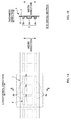
FIG. 1A is a plan view of an absorbentmain body 1 of a disposable diaper, andFIG. 1B is cross-sectional view taken along the line B-B inFIG. 1A . -
FIG. 2 is a schematic side view of amanufacturing apparatus 10 for the absorbentmain body 1. -
FIG. 3 is a perspective view of a rotatingdrum 20. -
FIG. 4A is a magnified view of a SAP-supply device 30, andFIG. 4B is a cross-sectional view taken along the line B-B inFIG. 4A . -
FIGS. 5A to 5C are explanatory diagrams showing a method for preventing the uneven deposit distribution of anabsorbent body 3 in the circumferential direction Dc. -
FIGS. 6A and 6B are respectively perspective views of the lowersliding plate 36 according to the modified examples. - At least the following matters will be made clear by the description in the present specification and the accompanying drawings.
- A manufacturing method for a composite sheet formed by sandwiching an absorbent body that absorbs liquid between a first sheet and a second sheet, including:
- conveying the first sheet with abutting a mold member on a surface of the mold member, the first sheet being continuous in a first direction, the mold member including a mold formed on the surface in a depressed shape and moving along the first direction perpendicular to a width direction of the surface;
- forming the absorbent body using a procedure in which a liquid-absorbent particle falls towards the first sheet abutting the surface and the liquid-absorbent particle is deposited on a corresponding portion of the first sheet to the mold by suction from a suction hole of the mold; and
- joining the second sheet and the first sheet with placing the second sheet over the first sheet, the first sheet having the absorbent body that is deposited thereon, the second sheet being continuously transported in the first direction, wherein
- in the forming, a plurality of slope members having a slope is included in an up-and-down direction,
- a height of an upstream end of the slope and a height of a downstream end of the slope are different in the first direction,
- while the liquid-absorbent particle successively slides a slope of the plurality of slope members, the liquid-absorbent particle is distributed in the width direction and falls on the first sheet located on the mold member,
- at least one slope member of the plurality of slope members makes the liquid-absorbent particle reverse its sliding direction and slide, the liquid-absorbent particle falling from a slope member adjacent above the one slope member.
- In such a manufacturing method for a composite sheet, at least one slope member makes the liquid-absorbent particle reverse its sliding direction, the liquid-absorbent particle falling from an adjacent slope member above it. And, the slope member makes the particle slide on a slope thereof. This makes it possible to lengthen the sliding-path length of the liquid-absorbent particle without making the manufacturing apparatus bigger in the first direction. Becasue of making the sliding-path length lengthen, the liquid-absorbent particle can be distributed evenly in the width direction. As a result thereof, the even deposit distribution of the liquid-absorbent particles in the width direction can be achieved.
- Further, because of reversing the sliding direction of the liquid-absorbent particle in conjunction with falling from the slope member, the liquid-absorbent particle is likely to be distributed. This also makes it possible to achieve the even deposit distribution of the liquid-absorbent particles in the width direction.
- In such a manufacturing method for a composite sheet, desirably
three or more of the slope members are included, and
concerning all of the slope members, sliding directions of slope members adjacent in the up-and-down direction are opposite from each other.
In such a manufacturing method for a composite sheet, under the condition in which the size of the manufacturing apparatus is restricted in the first direction, it is possible for sliding-path length of the liquid-absorbent particle to be longest. Further, the number of times the sliding direction is reversed in conjunction with falling is maximized. Therefore, the liquid-absorbent particle is more likely to be distributed evenly in the width direction. - In such a manufacturing method for a composite sheet, desirably
the mold of the mold member is formed at a predetermined interval in the first direction,
a lowermost slope member, of the plurality of slope members, drops the liquid-absorbent particle towards the first sheet located on the mold member,
in terms of the component along a horizontal direction, a sliding direction of the lowermost slope member is the same as a moving direction in which the mold member is moving at a landing position of the liquid-absorbent particle on the first sheet.
Such a manufacturing method for a composite sheet can prevent the uneven deposit distribution of the absorbent body in the first direction. The detail is as follows. The mold member moves in the first direction. Therefore, the liquid-absorbent particle is generally more likely to be deposited on the upstream side end of the mold in the first direction; that is, concerning the deposit distribution of the absorbent body, the deposit tends to be thicker on the upstream than on the downstream in the first direction. Concerning this point, if the sliding direction of the lowermost slope member is aligned with the moving direction of the mold member, the moving speed of the mold member with respect to the liquid-absorbent particles can be relatively slower. As a result thereof, it is possible to prevent an excess deposit on the upstream side of the mold, which prevents the uneven distribution of the deposit in the first direction. - In such a manufacturing method for a composite sheet, desirably
the mold member is a rotating drum continuously rotating in a rotating direction that is one direction of circumferential directions and is the first direction,
the rotating drum transports the first sheet with wrapping the sheet around an outer circumferential face at a predetermined wrapping angle, the outer circumferential face serving as the surface,
the mold is formed in a depressed shape on the outer circumferential face at a regular interval in the rotating direction,
a lower end of the lowermost slope member of the plurality of slope members is positioned, in the horizontal direction, at a top of the outer circumferential face of the rotating drum, or on a downstream side from the top in the rotating direction.
Such a manufacturing method for a composite sheet can prevent the uneven deposit distribution of the absorbent body in the rotating direction of the rotating drum. The detail is as follows.. The rotating drum rotates in the rotating direction. Therefore, the liquid-absorbent particle is generally more likely to be deposited on the upstream side end of the mold in the rotating direction; that is, concerning the deposit distribution of the absorbent body, the deposit tends to be thicker on the upstream than on the downstream in the rotating direction. Concerning this point, if the lower end of the lowermost slope member is located as mentioned above, the landing position of the liquid-absorbent particle is on the more downstream side of the rotating direction than the top of the outer circumferential face of the rotating drum, the landing position being a position at which the liquid-absorbent particle scattered from the lower end is landed on the rotating drum. Thus, the landed liquid-absorbent particle becomes likely to flow downstream because of a slope of the outer circumferential face, which is inclined to the downstream side. This results in preventing an excess deposit on the upstream side of the mold in the rotating direction. - In such a manufacturing method for a composite sheet, desirably
a slope of a slope member that receives the liquid-absorbent particle falling from a slope member adjacent above that slope member is arranged astride a lower end of the adjacent slope member in the first direction.
In such a manufacturing method for a composite sheet, all liquid-absorbent particles falling from the slope member adjacent above that slope member can be received. - In such a manufacturing method for a composite sheet, desirably
on a slope of the lowermost slope member of the plurality of slope members, a plurality of guiding grooves along the sliding direction are formed lined up in the width direction,
a position of a lower end of the guiding groove in the width direction is within the mold.
In such a manufacturing method for a composite sheet, the liquid-absorbent particle is guided by the guiding groove and is definitely led to the mold. Therefore, the amount of the liquid-absorbent particles that are deposited outside the mold can be reduced considerably. - In such a manufacturing method for a composite sheet, desirably
in the forming, a box member that forms a partitioned space together with the surface is included,
in the box member, the plurality of slope members are housed and a discharging member that discharges the liquid-absorbent particle is housed above the plurality of slope members,
both ends of the plurality of slope members in the width direction are fixed on a wall of the box member.
In such a manufacturing method for a composite sheet, it is difficult for the air to pass between the both edges of the slope members in the width direction and an inner wall of the box member. Therefore, an airflow which is flowing from the discharging member of the box member to the suction holes of the mold can be concentrated in the sliding direction of the liquid-absorbent particle, which results in a stable sliding of the liquid-absorbent particle. - In such a manufacturing method for a composite sheet, desirably
on a downstream side in the sliding direction of the lowermost slope member of the plurality of slope members, a wall is not arranged, the wall being hit by the liquid-absorbent particle that falls from the lowermost slope member and has not landed on the first sheet located on the mold member yet.
In such a manufacturing method for a composite sheet, the foregoing wall is not arranged. Therefore, without disturbing the state in which the liquid-absorbent particle is distributed substantially evenly by sliding on the slope member, the liquid-absorbent particle falls from the slope member and lands on the first sheet. This can make the deposit distribution of the absorbent body even in the width direction. - Further, a manufacturing apparatus for a composite sheet formed by sandwiching an absorbent body that absorbs liquid between a first sheet and a second sheet, including:
- a mold member that includes a mold formed on a surface in a depressed shape, that moves along a first direction perpendicular to a width direction of the surface, and that conveys the first sheet with the first sheet abutting on the surface, the first sheet being continuous in the first direction;
- a liquid-absorbent-particle-supply mechanism that drops and supplies the liquid-absorbent particle towards the first sheet abutting the surface;
- a suction mechanism that sucks air from a suction hole in the mold in order to form the absorbent body by depositing the liquid-absorbent particle on a corresponding portion of the first sheet to the mold; and
- a joining mechanism that places the second sheet over the first sheet on which the absorbent body is deposited and joins the sheets, the second sheet being continuously transported along the first direction, wherein
- the liquid-absorbent-particle-supply mechanism includes in an up-and-down direction a plurality of slope members having a slope,
- a height of an upstream end of the slope and a height of a downstream end of the slope are different from each other in the first direction,
- while the liquid-absorbent particle successively slides a slope of the plurality of slope members, the liquid-absorbent particle is distributed in the width direction and falls onto the first sheet on the mold member,
- at least one slope member of the plurality of slope members makes the liquid-absorbent particle reverse its sliding direction and slide, the liquid-absorbent particle falling from a slope member adjacent above the one slope member.
- Further, because of reversing the sliding direction of the liquid-absorbent particle in conjunction with falling from the slope member, the liquid-absorbent particle is more likely to be distributed. This also makes it possible to achieve the even deposit distribution of the liquid-absorbent particle in the width direction.
- A manufacturing method and manufacturing apparatus for a composite sheet according to the present embodiment is used for manufacturing an absorbent main body 1 (corresponding to a composite sheet) of a disposable diaper, for example.
-
FIGS. 1A and 1B are explanatory diagrams of the absorbentmain body 1 of a disposable diaper.FIG. 1A is a plan view, andFIG. 1B is a cross-sectional view taken along the line B-B inFIG. 1A . InFIG. 1A , a unit corresponding to a diaper product is shown by surrounding it by double-dotted chained line. - The absorbent
main body 1, among a plurality of components of a disposable diaper, corresponds to a component which comes into contact with the crotch of the wearer to absorb exudates such as urine etc. When viewed in a planar view, the absorbentmain body 1 has a substantially rectangular shape having a longitudinal direction and a width direction. In a thickness direction, anabsorbent body 3 to absorb liquid is covered with asurface sheet 5 from the surface side, which is the human-body side; theabsorbent body 3 is also covered with aback face sheet 7 from the back face side, which is the opposite side. And, in a state of sandwiching theabsorbent body 3 between thesesurface sheet 5 andback face sheet 7, thesurface sheet 5 and theback face sheet 7 are attached to each other in a frame-like manner at portions extending outwardly beyond four sides of theabsorbent body 3. - The
surface sheet 5 andback face sheet 7 are a liquid-permeable sheet; for example, nonwoven fabric made of synthetic fiber etc having a basis weight of 10 to 50 (g/m2). As a synthetic fiber, single fiber or conjugated fiber having a sheath-core structure such as polyethylene, polyethylene terephthalate etc can be provided for example. Theback face sheet 7 may be a liquid-impermeable sheet. - The
absorbent body 3 is made of particulate superabsorbent polymers having a particle diameter of 100 to 800 micrometer (corresponding to a liquid-absorbent particle, hereinafter referred to as SAP), and is formed by depositing the SAP at a basis weight of 100 to 500 (g/m2). Theabsorbent body 3 is configured by a plurality of island-shaped depositedportions 3a, 3b into which theabsorbent body 3 is divided in a predetermined depositing pattern in the longitudinal direction and width direction. In the example shown in the figures, theabsorbent body 3 is divided into three parts in each of the width direction and longitudinal direction. Theabsorbent body 3 includes a total of nine depositedportions 3a, 3b. Since the width direction corresponds to the left-and-right direction of a human body, thebody 3 is divided symmetrically into a plurality of portions relative to the center line of that width direction. The deposited portions 3a located at the center are set to be wider in width than the depositedportions 3b located at the both ends thereof. As a specific example of SAP, UG-840D (product of Sumitomo Seika Chemicals Co., Ltd.) etc is provided. -
FIG. 2 is a schematic side view of themanufacturing apparatus 10 for the absorbentmain body 1. At the point of this process in the course of manufacturing, in the same way asFIG. 1A , the absorbentmain body 1 is a continuous body that has not yet been divided into a product unit in the longitudinal direction. Further, the width direction of the absorbentmain body 1 is aligned in the width direction of the manufacturing apparatus 10 (a direction perpendicular to the paper surface inFIG. 2 ). Hereinafter this direction is referred to as merely the "width direction". In this regard, the width direction is horizontal. - This manufacturing method includes: (1) a conveying step (corresponding to "conveying") in which the surface sheet 5 (corresponding to a first sheet) is conveyed with wrapping the sheet 5 around the outer circumferential face 20a of the rotating drum 20 at a predetermined wrapping angle, the surface sheet 5 being continuous in the outer circumferential face 20a of a rotating drum 20, the rotating drum 20 rotating continuously along a rotating direction (corresponding to a first direction) that is one direction of the circumferential direction Dc; (2) a forming step (corresponding to "forming") in which the absorbent body 3 is formed using a procedure in which a SAP-supply device 30 drops and supplies the SAP towards the surface sheet 5 wrapped around the outer circumferential face 20a of the rotating drum 20 and the SAP is deposited on a corresponding portion of the surface sheet 5 to a mold 21 by suction from the suction holes of the mold, the mold being formed in a depressed shape on the outer circumferential face 20a of the rotating drum 20; and (3) a joining step (corresponding to "jointing") in which the back face sheet 7 (corresponding to a second sheet) is placed over the surface sheet 5 having the absorbent body 3 that is deposited thereon and the sheets are joined and integrated, the back face sheet 7 being continuously transported in the circumferential direction Dc.
-
FIG. 3 is a perspective view of therotating drum 20. The main body of the rotating drum 20 (corresponding to a mold member) is a cylinder that is driven and rotates about a horizontal axis C20 along the width direction. As shown inFIG. 3 , the outercircumferential face 20a (corresponding to a surface) of therotating drum 20 is horizontal with respect to the width direction. On the outercircumferential face 20a, themolds 21 of theabsorbent body 3 are disposed in a depressed shape at a regular interval in the circumferential direction Dc. Eachmold 21 is formed based on the foregoing depositing pattern; that is, each one of themolds 21 includes ninedepressions depressions rotating drum 20, the rotation angle range θ corresponding to at least the foregoing forming step. Thereby, in forming step ofFIG. 2 , SAP is deposited selectively on a corresponding portion of thesurface sheet 5 to each of thedepressions mold 21. - An example of a suction mechanism that makes the suction holes suck the air in the rotation angle range θ is as follow: having suction holes as through holes which communicate with an inner circumferential space of the
rotating drum 20; including a partition wall which partitions a corresponding space of the inner circumferential space to the rotation angle range θ; and connecting a negative pressure source such as a blower to the space in order to suck the air from the space. -
FIG. 4A is a magnified view of the SAP-supply device 30, andFIG. 4B is a cross-sectional view taken along line B-B inFIG. 4A . The SAP-supply device 30 (corresponding to a liquid-absorbent-particle-supply mechanism) is placed above a top 20t of the outercircumferential face 20a of therotating drum 20. The SAP-supply device 30 includes: abox member 31 which, together with that outercircumferential face 20a, forms a space SP located above the outercircumferential face 20a into a substantially closed space; a SAP-dischargingpipe 34 which is housed in thebox member 31 and discharges the SAP; and a plurality of slidingplates 36 which receive and distribute the SAP in the width direction while sliding of the SAP, the SAP being discharged and falling from the SAP-dischargingpipe 34. - The
box member 31 is, for example, a substantially rectangular parallelepiped lacking only a lower side wall, and include five walls except the lower side wall. Thebox member 31 is arranged with its lower surface being opposite the top 20t of the outercircumferential face 20a of therotating drum 20. Therefore, being surrounded by thebox member 31 prevents effectively SAP from scattering away. - Further, on a
wall 31u of thebox member 31 in the upper surface side, an air-inlet opening 32 is formed completely through the wall. Therefore, the air sucked from the suction holes of the foregoingmold 21 is entered from the air-inlet opening 32 into thebox member 31. This results in reducing an amount of the air which intrudes inside thebox member 31 from a gap G between alower end 31d of thebox member 31 and the outercircumferential face 20a of therotating drum 20. This effectively prevents disorder of the SAP in a falling direction or landing position, the SAP falling from thelower end 36d of the slidingplate 36 to thesurface sheet 5 that is located on therotating drum 20. - This air-
inlet opening 32 is preferably formed on a portion which is on thewall 31u on the upper surface side and is right above the SAP-dischargingpipe 34, as shown inFIG. 4A . This enables the air entered from the air-inlet opening 32 to concentrate on the SAP located on the slidingplate 36, which results in stable sliding of the SAP. - Further, the opening area of the air-
inlet opening 32 is preferably set to be larger than or equal to the total area of the gaps G that is between thelower end 31d of thebox member 31 and the outercircumferential face 20a of therotating drum 20. This can prevent intrusion of the air from the gap G more definitely. In this regard, in the case of thebox member 31, as shown inFIGS. 4A and 4B , thedownstream end 31d of thebox member 31 is formed by four walls:walls box member 31 includes in the upstream side and downstream side; and a pair ofside walls walls - The SAP-discharging pipe 34 (corresponding to a discharging member) is a pipelike member such as a round pipe. The SAP-discharging
pipe 34 is arranged above in thebox member 31, and a pipe axis C34 of thepipe 34 is aligned with the width direction. On a pipe wall (peripheral wall), a slit-shapeddischarge opening 34a along the width direction is formed completely through the wall. Inside the pipe, a helical screw feeder (not shown), which is for transporting the SAP in the width direction, is disposed and a rotational-axis direction thereof is aligned with the width direction. Further, at one end of the pipe ends of the SAP-dischargingpipe 34, the SAP is continuously supplied from the SAP supply source through suitable pipelines. Therefore, by rotation of the helical screw feeder, the SAP is transported from the one end of the pipe ends to the other pipe end in the SAP-dischargingpipe 34. While transporting, the SAP is discharged at each position in the width direction from thedischarge opening 34a. Therefore, the SAP is discharged from thedischarge opening 34a in the form of a curtain throughout the width direction. - A plurality of sliding plates 36 (corresponding to a plurality of slope members) are disposed side by side below the SAP-discharging
pipe 34 in a multilayered manner (three in the figures) in the up-and-down direction, with their positions differing in height. Therefore, the SAP which is discharged by the SAP-dischargingpipe 34 successively slides on the inclined upper surfaces (corresponding to slopes) of these slidingplates 36 from an upper slidingplate 36 via amiddle sliding plate 36 to a lower slidingplate 36. Thereafter, from the lower end of the lower slidingplate 36, the SAP is scattered in the form of a curtain throughout the width direction toward thesurface sheet 5 located on the outercircumferential face 20a of therotating drum 20,. - Each of the sliding
plates 36 is a rectangular plate whose upper surface is flat, for example. The upper surface is arranged horizontally in the width direction, in order to achieve even distribution of the SAP in the width direction. In the circumferential direction Dc, the upper surface is inclined with respect to the horizontal. In other words, the height of the upper surface atupstream end 36u (36d) in the rotating direction is different from the height atdownstream end 36d (36u). Therefore, the SAP slides in a direction parallel to the circumferential direction Dc as the sliding direction. However, there are two circumferential directions Dc: that is, a forward direction which is along the rotating direction of therotating drum 20, and the opposite direction. The direction of inclination of each slidingplate 36 decides the sliding direction of the SAP on that slidingplate 36. - In the example of
FIG. 4A , concerning all slidingplates 36, the directions of inclination of a pair of slidingplates plates 36 arranged in a multilayered manner in the up-and-down direction are in staggered arrangement. That is, on themiddle sliding plate 36, the SAP reverses its sliding direction and slides, the SAP falling from alower end 36d of the upper slidingplate 36 adjacent above it. On the lower slidingplate 36, the SAP reverses its sliding direction and slides, the SAP falling from alower end 36d of themiddle sliding plate 36 adjacent above it. - According to the arrangement of the sliding plates whose directions are opposite, while avoiding making the
manufacturing apparatus 10 bigger, the SAP can be distributed evenly in the width direction. A more specific description will be made below. - In order to distribute evenly particulate the SAP in the width direction, it is effective to lengthen a sliding-path length that the SAP rolls. However, in this case, a long sliding
plate 36 is needed, which results in making themanufacturing apparatus 10 bigger. In terms of this, in the case of reversing the sliding direction by setting to be opposite inclinations of the pair of slidingplates plates plates 36. This can prevent themanufacturing apparatus 10 from becoming bigger in size. - An angle of inclination α of the upper surface of the sliding
plate 36 with respect to the horizontal is selected within the range of angle greater than 0° and smaller than 90°. In the example shown in the figures, the inclination α of all slidingplates 36 is 30°. However, the inclination α may be different from each other. - Further, in the example shown in the figures, the
lower end 36d of each slidingplate 36 is located at the same position in the circumferential direction Dc throughout the width direction (seeFIG. 4B ) . This enables the landing position of the SAP falling from thelower end 36d to be organized throughout the width direction. As a result, disorder of the distribution of the SAP in the width direction, which is caused in conjunction with the falling, is suppressed. - Further, in the example shown in the figures, between the sliding
plates plate 36 is arranged astride thelower end 36d of the upper slidingplate 36 in the rotating direction. This enables the lower slidingplate 36 to receive all of the SAP falling from the upper slidingplate 36 definitely. This can prevent effectively the SAP from being deposited disorderly, the SAP leaking and reaching the outercircumferential face 20a of therotating drum 20. - As shown in
FIG. 4B , bothedges plate 36 in the width direction abut and are fixed to the pair ofside walls box member 31 at both ends in the width direction. Thereby, it becomes difficult for the air to pass between the bothedges plate 36 and an inner wall of thebox member 31. As a result, an airflow can be concentrated in the sliding direction of the SAP, the airflow flowing from a position of the SAP-dischargingpipe 34 of thebox member 31 to the suction holes of themold 21. This results in stable sliding of the SAP. - In order to increase this effect of stabilization, as shown with the double-dotted chained line in
FIG. 4A , it is preferable to close the space by placingvertical walls 37 between anupper edge 36u of each slidingplate 36 and anupper edge 36u of the slidingplate 36 adjacent above that slidingplate 36 or between theupper edge 36u of each slidingplate 36 and aceiling 31c of thebox member 31. This enables the foregoing airflow to be more stable. Further, scattering of the SAP can also be prevented; as a result, it is possible to effectively prevent the SAP from being deposited at any position other than thedepressions mold 21. In this regard, it is not necessay to place the foregoingvertical walls 37 concerning all of the sliding plates. Placing the walls for just any one of slidingplates 36 will have a reasonable effect. - Further, in the example shown in the figures, in terms of the component along the horizontal direction, the sliding direction of lower sliding
plate 36 is the same as the rotating direction (forward direction) of therotating drum 20 at the SAP landing position on thesurface sheet 5. This is for preventing uneven deposit distribution of theabsorbent body 3 in the circumferential direction Dc. -
FIG. 5A shows an explanatory diagram thereof. Therotating drum 20 rotates in the rotating direction. Therefore, in a case of dropping SAPs vertically for example, SAP is likely to roll on the upstream side of thedepression 21a (21b) of themold 21 in the rotating direction and to accumulate on anedge 22u on the upstream side. That is, the deposit distribution of theabsorbent body 3 tends to be thicker on the upstream than on the downstream in the rotating direction. Concerning this point, if, as shown in the reference example ofFIG. 5B , the sliding direction of the lower slidingplate 36 is set to be opposite to the rotating direction of therotating drum 20, the rotational speed of therotating drum 20 with respect to the SAP increases relatively. This encourages the deposit of the SAP on the upstream side mentioned above. As opposed thereto, if the sliding direction of the lower slidingplate 36 is the same as the rotating direction (forward direction) of therotating drum 20 as shown inFIG. 5C , the rotational speed of therotating drum 20 with respect to the SAP can lower relatively. This prevents the deposit on the upstream side of thedepression 21a (21b) of themold 21, which results in preventing the uneven deposit distribution in the circumferential direction Dc. - Further, in terms of preventing the uneven deposit distribution in the circumferential direction Dc, in the example of
FIG. 4A , thelower end 36d of the lower slidingplate 36 is positioned, in the horizontal direction, at the top 20t (the highest position) of the outercircumferential face 20a of therotating drum 20, or at the downstream side from the top 20t in the rotating direction. This can prevent the uneven deposit distribution of theabsorbent body 10 in the circumferential direction Dc. The detail is as follows. Because therotating drum 20 rotates as mentioned above, the deposit distribution of theabsorbent body 3 tends to be thicker on the upstream than on the downstream in the rotating direction. Concerning this point, if thelower end 36d of the lower slidingplate 36 is positioned as mentioned above, the landing position of the SAP on therotating drum 20 is on the downstream side in the rotating direction from the top 20t of the outercircumferential face 20a of therotating drum 20, the SAP being scattered from thelower end 36d. Because of inclination of the outercircumferential face 20a towards the downstream side, the SAP which has landed is more likely to flow downstream, which results in preventing an excess deposit on the upstream side of thedepression 21a (21b) of themold 21. - It is preferable that, as shown in
FIG. 4A , on the downstream side of the sliding direction of the lower slidingplate 36, a wall is not arranged with which the SAP that falls from the slidingplate 36 comes into contact before the SAP lands on thesurface sheet 5 located on therotating drum 20. In this case, while transferring the SAP from the lower slidingplate 36 to thesurface sheet 5 located on therotating drum 20, the state of the SAP is not distrubed in which the SAP is distributed evenly by sliding on the lower slidingplate 36, and the SAP falls from thelower end 36d of the slidingplate 36 and lands on thesurface sheet 5. This makes it possible to achieve the even deposit distribution of theabsorbent body 3 in the width direction. -
FIG. 6A is a perspective view of lower slidingplate 36 of the modified example of. In the foregoing example, the upper surface of slidingplate 36 is a flat surface. However, in the modified example, on the upper surface of the slidingplate 36, a plurality of guidinggrooves grooves depression FIG. 3 ). That is, the central position of each guidinggrooves depressions grooves depressions mold 21, which results in preventing effectively falling of the SAP outside each of thedepressions - Instead of the foregoing guiding
grooves lower end 36d of the sliding plate rod-shapedguide members 39 which are located along the circumferential direction Dc, and to lead the SAP to each of thedepressions mold 21, as shown in the perspective view ofFIG. 6B . In this case, theguide members 39 are arranged, with respect to the width direction, at a position where thedepressions mold 21 do not exist. - In the final joining step, as shown in
FIG. 2 , thesurface sheet 5 andback face sheet 7 are joined with placing theback face sheet 7 over thesurface sheet 5 on which theabsorbent body 3 is deposited. More specifically, at a position on the more downstream side than the installed position of the foregoing SAP-supply device 30 in the rotating direction of therotating drum 20, theback face sheet 7 is supplied by continuously rolling out from a reel (not shown) and is placed over thesurface sheet 5. Onto thisback face sheet 7, hot-melt adhesive is applied, in advance, by an adhesive-applyingdevice 50 in strips along the circumferential direction Dc, lined up at a regular interval in the width direction. Thereby, theback face sheet 7 adheres to thesurface sheet 5, and a continuous body of the foregoing absorbentmain body 1 is formed. - Thereafter, the continuous body of the absorbent
main body 1 is removed from the outercircumferential face 20a of therotating drum 20 at a predetermined position on therotating drum 20, and is transferred to a pair of upper and lowerheat sealing rollers heat sealing roller 60a, depressions corresponding to the depositing pattern are formed; thereby thesurface sheet 5 andback face sheet 7 are hot-melt bonded, except areas of the absorbentmain body 1 where the island-shaped depositedportions 3a, 3b of theabsorbent body 3 are located. - It is also possible that an adhesive-applying
device 70 shown inFIG. 2 applies the hot-melt adhesive onto thesurface sheet 5 in the foregoing depositing pattern, before wrapping thesurface sheet 5 around therotating drum 20. In this case, the SAP which is led to thedepressions mold 21 can be fixed quickly and securely to portions of thesurface sheet 5 which are at the same position as the depressions.
In this regard, the foregoing reel, the adhesive-applyingdevice heat sealing rollers - Embodiments of the present invention have been described as above, however the present invention is not limited to these embodiments and the following variations are also possible.
- In the foregoing embodiment, concerning all sliding
plates 36, the sliding directions of a pair of the slidingplates plate 36 of a plurality of slidingplates 36 makes the SAP reverse its sliding direction and slide, the SAP falling from the adjacent slidingplate 36 above it. Among a plurality of pairs of the slidingplates - In the foregoing embodiment, the
rotating drum 20 is provided as a mold member. However, the invention is not limited thereto. For example, it is possible to use a belt of a belt conveyor as a mold member, to form themolds 21 in a depressed shape on the belt, and to move the belt along a predetermined path. - In the foregoing embodiment, a direction in which the
discharge opening 34a of the SAP-dischargingpipe 34 is facing is not described in detail. As shown inFIG. 4A , thedischarge opening 34a is preferably facing, not vertically below, to anupper edge 36d of the uppermost slidingplate 36 which has to directly receive the SAP discharged by the SAP-dischargingpipe 34. This makes it possible to ensure long sliding-path length of the SAP on the slidingplates 36. Therefore, the evenness of the distribution of the SAP increases in the width direction. - In the foregoing embodiment, the SAP is provided as a liquid-absorbent particle. However, the invention is not limited to superabsorbent polymer as long as a liquid-absorbent particle is a particle having a property to keep absorbed liquid by swelling etc.
- In the foregoing embodiment, three of sliding
plates 36 are included. However, the invention is not limited thereto as long as a plurality of the slidingplates 36 are included. - In the foregoing embodiment, the case where the
mold 21 has a bottom section on which a plurality of suction holes are formed is provided. However, the invention is not limited thereto. For example, themold 21 does not have to have the bottom section; in other words, themold 21 may be one through hole that is formed completely through the outercircumferential face 20a of therotating drum 20 in the thickness direction. In this way, themold 21 itself may be a suction hole. As a specific example of the foregoing bottom section of themold 21, a mesh plate such as a woven wire cloth etc can be provided. - In the foregoing embodiment, nonwoven fabric made of synthetic fiber is provided as an example of materials of the
surface sheet 5. However, the invention is not limited thereto as long as materials have air-permeability. For example, tissue paper, sheet-like pulverized pulp or the like can be employed. - In the foregoing embodiment, nonwoven fabric made of synthetic fiber is provided as an example of materials of the
back face sheet 7. However, the invention is not limited thereto. For example, tissue paper, sheet-like pulverized pulp or the like can be employed. - 1 absorbent main body (composite sheet), 3 absorbent body, 3a deposited portion, 3b deposited portion, 5 surface sheet (first sheet), 7 back face sheet (second sheet), 10 manufacturing apparatus, 20 rotating drum (mold member), 20a outer circumferential face (surface), 20t top, 21 mold, 21a depression, 21b depression, 22u edge on upstream side, 30 SAP-supply device(liquid-absorbent-particle-supply mechanism), 31 box member, 31c ceiling, 31d lower end, 31e wall on upstream side, 31f wall on downstream side, 31s side wall, 31u wall on upper surface side, 32 air-inlet opening, 34 SAP-discharging pipe (discharging member), 34a discharge opening, 36 sliding plate (slope member), 36d lower end (downstream end, upstream end), 36s both edges, 36u upper edge (downstream end, upstream end), 37 vertical wall, 38a guiding groove, 38b guiding groove, 39 guide member, 50 adhesive-applying device, 60a heat sealing roller, 60b heat sealing roller, 70 adhesive-applying device, C20 horizontal axis, C34 pipe axis
Claims (9)
- A manufacturing method for a composite sheet formed by sandwiching an absorbent body that absorbs liquid between a first sheet and a second sheet, comprising:conveying the first sheet with abutting a mold member on a surface of the mold member, the first sheet being continuous in a first direction, the mold member including a mold formed on the surface in a depressed shape and moving along the first direction perpendicular to a width direction of the surface;forming the absorbent body using a procedure in which a liquid-absorbent particle falls towards the first sheet abutting the surface and the liquid-absorbent particle is deposited on a corresponding portion of the first sheet to the mold by suction from a suction hole of the mold; andjoining the second sheet and the first sheet with placing the second sheet over the first sheet, the first sheet having the absorbent body that is deposited thereon, the second sheet being continuously transported in the first direction, whereinin the forming, a plurality of slope members having a slope is included in an up-and-down direction,a height of an upstream end of the slope and a height of a downstream end of the slope are different in the first direction,while the liquid-absorbent particle successively slides a slope of the plurality of slope members, the liquid-absorbent particle is distributed in the width direction and falls on the first sheet located on the mold member,at least one slope member of the plurality of slope members makes the liquid-absorbent particle reverse its sliding direction and slide, the liquid-absorbent particle falling from a slope member adjacent above the one slope member.
- A manufacturing method for a composite sheet according to claim 1, wherein
three or more of the slope members are included, and concerning all of the slope members, sliding directions of slope members adjacent in the up-and-down direction are opposite from each other. - A manufacturing method for a composite sheet according to claim 1 or 2, wherein
the mold of the mold member is formed at a predetermined interval in the first direction,
a lowermost slope member, of the plurality of slope members, drops the liquid-absorbent particle towards the first sheet located on the mold member,
in terms of the component along a horizontal direction, a sliding direction of the lowermost slope member is the same as a moving direction in which the mold member is moving at a landing position of the liquid-absorbent particle on the first sheet. - A manufacturing method for a composite sheet according to any one of claims 1 to 3, wherein
the mold member is a rotating drum continuously rotating in a rotating direction that is one direction of circumferential directions and is the first direction,
the rotating drum transports the first sheet with wrapping the sheet around an outer circumferential face at a predetermined wrapping angle, the outer circumferential face serving as the surface,
the mold is formed in a depressed shape on the outer circumferential face at a regular interval in the rotating direction,
a lower end of the lowermost slope member of the plurality of slope members is positioned, in the horizontal direction, at a top of the outer circumferential face of the rotating drum, or on a downstream side from the top in the rotating direction. - A manufacturing method for a composite sheet according to any one of claims 1 to 4, wherein
a slope of a slope member that receives the liquid-absorbent particle falling from a slope member adjacent above that slope member is arranged astride a lower end of the adjacent slope member in the first direction. - A manufacturing method for a composite sheet according to any one of claims 1 to 5, wherein
on a slope of the lowermost slope member of the plurality of slope members, a plurality of guiding grooves along the sliding direction are formed lined up in the width direction,
a position of a lower end of the guiding groove in the width direction is within the mold. - A manufacturing method for a composite sheet according to any one of claims 1 to 6, wherein
in the forming, a box member that forms a partitioned space together with the surface is included,
in the box member, the plurality of slope members are housed and a discharging member that discharges the liquid-absorbent particle is housed above the plurality of slope members,
both ends of the plurality of slope members in the width direction are fixed on a wall of the box member. - A manufacturing method for a composite sheet according to any one of claims 1 to 7, wherein
on a downstream side in the sliding direction of the lowermost slope member of the plurality of slope members, a wall is not arranged, the wall being hit by the liquid-absorbent particle that falls from the lowermost slope member and has not landed on the first sheet located on the mold member yet. - A manufacturing apparatus for a composite sheet formed by sandwiching an absorbent body that absorbs liquid between a first sheet and a second sheet, comprising:a mold member that includes a mold formed on a surface in a depressed shape, that moves along a first direction perpendicular to a width direction of the surface, and that conveys the first sheet with the first sheet abutting on the surface, the first sheet being continuous in the first direction;a liquid-absorbent-particle-supply mechanism that drops and supplies the liquid-absorbent particle towards the first sheet abutting the surface;a suction mechanism that sucks air from a suction hole in the mold in order to form the absorbent body by depositing the liquid-absorbent particle on a corresponding portion of the first sheet to the mold; anda joining mechanism that places the second sheet over the first sheet on which the absorbent body is deposited and joins the sheets, the second sheet being continuously transported along the first direction, whereinthe liquid-absorbent-particle-supply mechanism includes in an up-and-down direction a plurality of slope members having a slope,a height of an upstream end of the slope and a height of a downstream end of the slope are different from each other in the first direction,while the liquid-absorbent particle successively slides a slope of the plurality of slope members, the liquid-absorbent particle is distributed in the width direction and falls onto the first sheet on the mold member,at least one slope member of the plurality of slope members makes the liquid-absorbent particle reverse its sliding direction and slide, the liquid-absorbent particle falling from a slope member adjacent above the one slope member.
Applications Claiming Priority (2)
| Application Number | Priority Date | Filing Date | Title |
|---|---|---|---|
| JP2009070650A JP5264583B2 (en) | 2009-03-23 | 2009-03-23 | Composite sheet manufacturing method and manufacturing apparatus |
| PCT/JP2010/052406 WO2010109986A1 (en) | 2009-03-23 | 2010-02-18 | Process and device for producing composite sheet |
Publications (1)
| Publication Number | Publication Date |
|---|---|
| EP2412346A1 true EP2412346A1 (en) | 2012-02-01 |
Family
ID=42780682
Family Applications (1)
| Application Number | Title | Priority Date | Filing Date |
|---|---|---|---|
| EP10755787A Withdrawn EP2412346A1 (en) | 2009-03-23 | 2010-02-18 | Process and device for producing composite sheet |
Country Status (5)
| Country | Link |
|---|---|
| US (1) | US8597458B2 (en) |
| EP (1) | EP2412346A1 (en) |
| JP (1) | JP5264583B2 (en) |
| CN (1) | CN102361612B (en) |
| WO (1) | WO2010109986A1 (en) |
Cited By (5)
| Publication number | Priority date | Publication date | Assignee | Title |
|---|---|---|---|---|
| WO2013008434A1 (en) * | 2011-07-08 | 2013-01-17 | Livedo Corporation | Particle supplying apparatus and sheet article manufacturing apparatus |
| WO2013008432A1 (en) * | 2011-07-08 | 2013-01-17 | Livedo Corporation | Particle supplying apparatus and sheet article manufacturing apparatus |
| ITBO20130232A1 (en) * | 2013-05-20 | 2014-11-21 | Gdm Spa | MACHINE AND METHOD FOR THE REALIZATION OF HYGIENIC ABSORBENT ITEMS. |
| WO2015074639A1 (en) * | 2013-11-20 | 2015-05-28 | Imeco Gmbh & Co. Kg | Device and method for producing a composite |
| EP2666448A4 (en) * | 2011-01-19 | 2015-09-30 | Uni Charm Corp | Apparatus for producing absorber |
Families Citing this family (19)
| Publication number | Priority date | Publication date | Assignee | Title |
|---|---|---|---|---|
| JP5386123B2 (en) * | 2008-07-31 | 2014-01-15 | ユニ・チャーム株式会社 | Absorber manufacturing apparatus and manufacturing method |
| EP2329803B1 (en) * | 2009-12-02 | 2019-06-19 | The Procter & Gamble Company | Apparatus and method for transferring particulate material |
| JP6063925B2 (en) * | 2011-08-30 | 2017-01-18 | ユニ・チャーム株式会社 | Absorbent sheet-like member inspection apparatus and inspection method for absorbent articles |
| ITTO20111028A1 (en) * | 2011-11-08 | 2012-02-07 | Fameccanica Data Spa | EQUIPMENT AND PROCEDURE FOR FORMING ABSORBENT COREBOARDS FOR ABSORBENT SANITARY PRODUCTS |
| JP5996448B2 (en) * | 2013-01-31 | 2016-09-21 | ユニ・チャーム株式会社 | Absorbent article manufacturing apparatus and absorbent article manufacturing method |
| CN104546299B (en) * | 2015-01-29 | 2018-06-05 | 福建省时代天和实业有限公司 | A kind of former for producing anti-fracture paper diaper |
| JP6911979B2 (en) * | 2016-04-26 | 2021-07-28 | 王子ホールディングス株式会社 | Absorber manufacturing equipment and manufacturing method |
| JP6720674B2 (en) * | 2016-04-26 | 2020-07-08 | 王子ホールディングス株式会社 | Absorber manufacturing apparatus and manufacturing method |
| JP6808461B2 (en) * | 2016-11-29 | 2021-01-06 | 花王株式会社 | Sheet-shaped manufacturing method and manufacturing equipment |
| JP6412973B2 (en) * | 2017-03-28 | 2018-10-24 | 大王製紙株式会社 | Particulate spraying device and spraying method |
| JP6914117B2 (en) * | 2017-06-28 | 2021-08-04 | 大王製紙株式会社 | Spraying device and spraying method |
| CN111093377B (en) * | 2017-09-05 | 2022-07-15 | 莱特拉姆有限责任公司 | Individualization and Separation System for Shrimp Processors |
| JP2019042424A (en) * | 2017-09-07 | 2019-03-22 | 王子ホールディングス株式会社 | Supplying member and manufacturing apparatus for absorbent article |
| US12390376B2 (en) | 2018-02-28 | 2025-08-19 | Kimberly-Clark Worldwide, Inc. | Multi-layer absorbent cores and methods of manufacture |
| JP7321114B2 (en) * | 2019-04-26 | 2023-08-04 | ユニ・チャーム株式会社 | Fluid placement method for absorbent article and absorbent article |
| CN109968575B (en) * | 2019-05-16 | 2024-03-29 | 江苏科润膜材料有限公司 | Steel belt casting machine for producing enhanced perfluorinated ion exchange membrane |
| CN110123530B (en) * | 2019-06-05 | 2024-07-26 | 无锡优佳无纺科技有限公司 | Water-absorbing core production line |
| CN116963705A (en) | 2021-03-30 | 2023-10-27 | 金伯利-克拉克环球有限公司 | Multilayer absorbent core and method of making same |
| US12612243B2 (en) * | 2022-07-29 | 2026-04-28 | Express Scripts Strategic Development, Inc. | Hopper for a pharmaceutical counter |
Family Cites Families (14)
| Publication number | Priority date | Publication date | Assignee | Title |
|---|---|---|---|---|
| US2962381A (en) * | 1957-07-02 | 1960-11-29 | Congoleum Nairn Inc | Segment wheel feeder |
| US3283740A (en) * | 1963-05-20 | 1966-11-08 | Stuart P Kessler | Distributing apparatus for granular materials |
| US3590981A (en) * | 1969-05-01 | 1971-07-06 | Fruit Harvesting Co Inc | Guide with energy-absorbing baffles |
| ZA75479B (en) * | 1974-02-04 | 1976-08-25 | Colgate Palmolive Co | Disposable diaper with holes or wells |
| JPS54141099A (en) * | 1978-04-24 | 1979-11-01 | Daiichi Eizai Kk | Method of fabricating water absorber |
| US4571924A (en) * | 1985-04-29 | 1986-02-25 | The Procter & Gamble Company | Method and apparatus of manufacturing porous pouches containing granular product |
| SE468305B (en) * | 1991-04-24 | 1992-12-14 | Moelnlycke Ab | PROCEDURE AND DEVICE FOR APPLYING PARTICLES TO A CURRENT MATERIAL |
| JP2001071029A (en) | 1999-09-08 | 2001-03-21 | Nidec Copal Corp | Roll leveler |
| JP4152049B2 (en) | 1999-12-22 | 2008-09-17 | 花王株式会社 | Method for producing particle deposit |
| US6390280B1 (en) * | 2000-02-15 | 2002-05-21 | Keith W. Boyce | Feed hopper with baffle plates |
| MXPA03010110A (en) * | 2001-05-04 | 2005-03-07 | Korma Spa | Method and device for production of a number of laminates. |
| JP2004341803A (en) * | 2003-05-15 | 2004-12-02 | Nec Corp | Method and system for optimizing transmission/reception of message |
| JP2004351803A (en) * | 2003-05-29 | 2004-12-16 | Livedo Corporation | Method and apparatus for producing sheet-like absorber |
| JP2007050380A (en) * | 2005-08-19 | 2007-03-01 | Zuiko Corp | Intermittent spraying device for powder and granular materials in worn articles |
-
2009
- 2009-03-23 JP JP2009070650A patent/JP5264583B2/en active Active
-
2010
- 2010-02-18 WO PCT/JP2010/052406 patent/WO2010109986A1/en not_active Ceased
- 2010-02-18 US US13/258,977 patent/US8597458B2/en not_active Expired - Fee Related
- 2010-02-18 CN CN201080013207.2A patent/CN102361612B/en not_active Expired - Fee Related
- 2010-02-18 EP EP10755787A patent/EP2412346A1/en not_active Withdrawn
Non-Patent Citations (1)
| Title |
|---|
| See references of WO2010109986A1 * |
Cited By (8)
| Publication number | Priority date | Publication date | Assignee | Title |
|---|---|---|---|---|
| EP2666448A4 (en) * | 2011-01-19 | 2015-09-30 | Uni Charm Corp | Apparatus for producing absorber |
| WO2013008434A1 (en) * | 2011-07-08 | 2013-01-17 | Livedo Corporation | Particle supplying apparatus and sheet article manufacturing apparatus |
| WO2013008432A1 (en) * | 2011-07-08 | 2013-01-17 | Livedo Corporation | Particle supplying apparatus and sheet article manufacturing apparatus |
| US9283119B2 (en) | 2011-07-08 | 2016-03-15 | Livedo Corporation | Particle supplying apparatus and sheet article manufacturing apparatus |
| US9365023B2 (en) | 2011-07-08 | 2016-06-14 | Livedo Corporation | Particle supplying apparatus and sheet article manufacturing apparatus |
| ITBO20130232A1 (en) * | 2013-05-20 | 2014-11-21 | Gdm Spa | MACHINE AND METHOD FOR THE REALIZATION OF HYGIENIC ABSORBENT ITEMS. |
| WO2014188302A1 (en) * | 2013-05-20 | 2014-11-27 | Gdm S.P.A. | Machine and method for making absorbent sanitary articles |
| WO2015074639A1 (en) * | 2013-11-20 | 2015-05-28 | Imeco Gmbh & Co. Kg | Device and method for producing a composite |
Also Published As
| Publication number | Publication date |
|---|---|
| CN102361612A (en) | 2012-02-22 |
| US20120056347A1 (en) | 2012-03-08 |
| JP5264583B2 (en) | 2013-08-14 |
| WO2010109986A1 (en) | 2010-09-30 |
| CN102361612B (en) | 2014-06-25 |
| US8597458B2 (en) | 2013-12-03 |
| JP2010220768A (en) | 2010-10-07 |
Similar Documents
| Publication | Publication Date | Title |
|---|---|---|
| US8597458B2 (en) | Manufacturing method and a manufacturing apparatus for a composite sheet | |
| EP2666448B1 (en) | Apparatus for producing absorber | |
| CN102665626B (en) | Method and device for manufacturing absorption body | |
| US8221672B2 (en) | Method and apparatus for forming a batt of particulate material for use as a component in an absorbent core assembly | |
| US6652798B1 (en) | Method and an apparatus for forming air-laid fibrous absorbent cores | |
| US11311424B2 (en) | Absorbent cores and methods for forming absorbent cores | |
| US20140144586A1 (en) | Particle supplying apparatus and sheet article manufacturing apparatus | |
| US20110049758A1 (en) | Apparatus and method for manufacturing absorbent body | |
| CN105813609A (en) | Device for manufacturing absorption bodies | |
| TWI590812B (en) | Absorber manufacturing apparatus of absorbent article, and manufacturing method | |
| JP5475434B2 (en) | Absorbent manufacturing method and manufacturing apparatus | |
| JP6838950B2 (en) | Sheet folding device and manufacturing method of absorber using it | |
| JP6591136B2 (en) | Absorber and absorbent article manufacturing method, and absorbent body and absorbent article manufacturing apparatus | |
| JP6620271B2 (en) | Method for manufacturing absorbent body and method for manufacturing absorbent article | |
| JP6699980B2 (en) | Absorber manufacturing method and absorber manufacturing apparatus | |
| JP5296663B2 (en) | Absorbent manufacturing method and manufacturing apparatus | |
| EP4005543B1 (en) | Manufacturing device and manufacturing method of absorber | |
| JP6851910B2 (en) | Sheet folding device and manufacturing method of absorber using it | |
| JP6421024B2 (en) | Absorbent manufacturing method and manufacturing apparatus | |
| RU2774288C2 (en) | Method for manufacture of sheet elements, device for manufacture of sheet elements and method for production of absorbing mass |
Legal Events
| Date | Code | Title | Description |
|---|---|---|---|
| PUAI | Public reference made under article 153(3) epc to a published international application that has entered the european phase |
Free format text: ORIGINAL CODE: 0009012 |
|
| 17P | Request for examination filed |
Effective date: 20110923 |
|
| AK | Designated contracting states |
Kind code of ref document: A1 Designated state(s): AT BE BG CH CY CZ DE DK EE ES FI FR GB GR HR HU IE IS IT LI LT LU LV MC MK MT NL NO PL PT RO SE SI SK SM TR |
|
| DAX | Request for extension of the european patent (deleted) | ||
| STAA | Information on the status of an ep patent application or granted ep patent |
Free format text: STATUS: THE APPLICATION HAS BEEN WITHDRAWN |
|
| 18W | Application withdrawn |
Effective date: 20140206 |