EP2412317B1 - Wound closure device - Google Patents
Wound closure device Download PDFInfo
- Publication number
- EP2412317B1 EP2412317B1 EP11250682.9A EP11250682A EP2412317B1 EP 2412317 B1 EP2412317 B1 EP 2412317B1 EP 11250682 A EP11250682 A EP 11250682A EP 2412317 B1 EP2412317 B1 EP 2412317B1
- Authority
- EP
- European Patent Office
- Prior art keywords
- suturing device
- trajectory guide
- arm member
- suture
- longitudinal axis
- Prior art date
- Legal status (The legal status is an assumption and is not a legal conclusion. Google has not performed a legal analysis and makes no representation as to the accuracy of the status listed.)
- Active
Links
- 230000007246 mechanism Effects 0.000 claims description 16
- 238000004873 anchoring Methods 0.000 claims description 4
- 230000000717 retained effect Effects 0.000 claims description 2
- 210000001519 tissue Anatomy 0.000 description 41
- 238000000034 method Methods 0.000 description 6
- 206010052428 Wound Diseases 0.000 description 5
- 238000000605 extraction Methods 0.000 description 4
- 208000027418 Wounds and injury Diseases 0.000 description 3
- CURLTUGMZLYLDI-UHFFFAOYSA-N Carbon dioxide Chemical compound O=C=O CURLTUGMZLYLDI-UHFFFAOYSA-N 0.000 description 2
- 210000003815 abdominal wall Anatomy 0.000 description 2
- 239000000853 adhesive Substances 0.000 description 2
- 230000001070 adhesive effect Effects 0.000 description 2
- 210000003484 anatomy Anatomy 0.000 description 2
- 238000003780 insertion Methods 0.000 description 2
- 230000037431 insertion Effects 0.000 description 2
- 238000012986 modification Methods 0.000 description 2
- 230000004048 modification Effects 0.000 description 2
- 238000001356 surgical procedure Methods 0.000 description 2
- 206010021620 Incisional hernias Diseases 0.000 description 1
- FAPWRFPIFSIZLT-UHFFFAOYSA-M Sodium chloride Chemical compound [Na+].[Cl-] FAPWRFPIFSIZLT-UHFFFAOYSA-M 0.000 description 1
- 210000000683 abdominal cavity Anatomy 0.000 description 1
- 230000001154 acute effect Effects 0.000 description 1
- 239000000560 biocompatible material Substances 0.000 description 1
- 229910002092 carbon dioxide Inorganic materials 0.000 description 1
- 239000001569 carbon dioxide Substances 0.000 description 1
- 238000012976 endoscopic surgical procedure Methods 0.000 description 1
- 210000003195 fascia Anatomy 0.000 description 1
- 208000014674 injury Diseases 0.000 description 1
- 239000007788 liquid Substances 0.000 description 1
- 239000000463 material Substances 0.000 description 1
- 210000004303 peritoneum Anatomy 0.000 description 1
- 238000011321 prophylaxis Methods 0.000 description 1
- 239000011780 sodium chloride Substances 0.000 description 1
- 230000008733 trauma Effects 0.000 description 1
- XLYOFNOQVPJJNP-UHFFFAOYSA-N water Substances O XLYOFNOQVPJJNP-UHFFFAOYSA-N 0.000 description 1
Images


Classifications
-
- A—HUMAN NECESSITIES
- A61—MEDICAL OR VETERINARY SCIENCE; HYGIENE
- A61B—DIAGNOSIS; SURGERY; IDENTIFICATION
- A61B17/00—Surgical instruments, devices or methods, e.g. tourniquets
- A61B17/04—Surgical instruments, devices or methods, e.g. tourniquets for suturing wounds; Holders or packages for needles or suture materials
- A61B17/0469—Suturing instruments for use in minimally invasive surgery, e.g. endoscopic surgery
-
- A—HUMAN NECESSITIES
- A61—MEDICAL OR VETERINARY SCIENCE; HYGIENE
- A61B—DIAGNOSIS; SURGERY; IDENTIFICATION
- A61B17/00—Surgical instruments, devices or methods, e.g. tourniquets
- A61B17/0057—Implements for plugging an opening in the wall of a hollow or tubular organ, e.g. for sealing a vessel puncture or closing a cardiac septal defect
-
- A—HUMAN NECESSITIES
- A61—MEDICAL OR VETERINARY SCIENCE; HYGIENE
- A61B—DIAGNOSIS; SURGERY; IDENTIFICATION
- A61B17/00—Surgical instruments, devices or methods, e.g. tourniquets
- A61B17/04—Surgical instruments, devices or methods, e.g. tourniquets for suturing wounds; Holders or packages for needles or suture materials
- A61B17/0482—Needle or suture guides
-
- A—HUMAN NECESSITIES
- A61—MEDICAL OR VETERINARY SCIENCE; HYGIENE
- A61B—DIAGNOSIS; SURGERY; IDENTIFICATION
- A61B17/00—Surgical instruments, devices or methods, e.g. tourniquets
- A61B17/0057—Implements for plugging an opening in the wall of a hollow or tubular organ, e.g. for sealing a vessel puncture or closing a cardiac septal defect
- A61B2017/00575—Implements for plugging an opening in the wall of a hollow or tubular organ, e.g. for sealing a vessel puncture or closing a cardiac septal defect for closure at remote site, e.g. closing atrial septum defects
- A61B2017/00597—Implements comprising a membrane
-
- A—HUMAN NECESSITIES
- A61—MEDICAL OR VETERINARY SCIENCE; HYGIENE
- A61B—DIAGNOSIS; SURGERY; IDENTIFICATION
- A61B17/00—Surgical instruments, devices or methods, e.g. tourniquets
- A61B17/0057—Implements for plugging an opening in the wall of a hollow or tubular organ, e.g. for sealing a vessel puncture or closing a cardiac septal defect
- A61B2017/00575—Implements for plugging an opening in the wall of a hollow or tubular organ, e.g. for sealing a vessel puncture or closing a cardiac septal defect for closure at remote site, e.g. closing atrial septum defects
- A61B2017/0061—Implements located only on one side of the opening
-
- A—HUMAN NECESSITIES
- A61—MEDICAL OR VETERINARY SCIENCE; HYGIENE
- A61B—DIAGNOSIS; SURGERY; IDENTIFICATION
- A61B17/00—Surgical instruments, devices or methods, e.g. tourniquets
- A61B17/0057—Implements for plugging an opening in the wall of a hollow or tubular organ, e.g. for sealing a vessel puncture or closing a cardiac septal defect
- A61B2017/00575—Implements for plugging an opening in the wall of a hollow or tubular organ, e.g. for sealing a vessel puncture or closing a cardiac septal defect for closure at remote site, e.g. closing atrial septum defects
- A61B2017/00623—Introducing or retrieving devices therefor
-
- A—HUMAN NECESSITIES
- A61—MEDICAL OR VETERINARY SCIENCE; HYGIENE
- A61B—DIAGNOSIS; SURGERY; IDENTIFICATION
- A61B17/00—Surgical instruments, devices or methods, e.g. tourniquets
- A61B17/0057—Implements for plugging an opening in the wall of a hollow or tubular organ, e.g. for sealing a vessel puncture or closing a cardiac septal defect
- A61B2017/00637—Implements for plugging an opening in the wall of a hollow or tubular organ, e.g. for sealing a vessel puncture or closing a cardiac septal defect for sealing trocar wounds through abdominal wall
-
- A—HUMAN NECESSITIES
- A61—MEDICAL OR VETERINARY SCIENCE; HYGIENE
- A61B—DIAGNOSIS; SURGERY; IDENTIFICATION
- A61B17/00—Surgical instruments, devices or methods, e.g. tourniquets
- A61B17/0057—Implements for plugging an opening in the wall of a hollow or tubular organ, e.g. for sealing a vessel puncture or closing a cardiac septal defect
- A61B2017/00646—Type of implements
- A61B2017/00663—Type of implements the implement being a suture
Definitions
- the present disclosure relates to a wound closure device and, more particularly, to a wound closure device for suturing an opening in tissue.
- a trocar device is utilized to puncture the peritoneum to provide an access port by way of a cannula through the abdominal wall.
- a trocar and/or cannula is placed through the abdominal wall for introduction of surgical instrumentation which is necessary to carry out the surgical procedure.
- the surgeon may introduce a surgical instrument such as a grasper, scissor, clip applier, stapler or any other surgical instrument which may be necessary during the particular surgical procedure.
- Conventional instruments for closing puncture wounds generally include a shaft that can be extended into the body through either the puncture wound itself (in the case of a puncture caused by trauma) or through a cannula (in the case of a puncture created to access a surgical site). Suture retaining needles are then deployed from the shaft into tissue. Unfortunately, the mechanisms used for deploying the needles are often cumbersome and may make the extension and/or retraction of the suturing device difficult.
- WO2010/081096 US2001/031973 and US2008/033459 disclose various suturing devices.
- a suturing device in accordance with the present invention, includes an elongate shaft defining a longitudinal axis, a trajectory guide mounted on the elongate shaft and an introducer guard member operatively coupled to the elongate shaft.
- the trajectory guide defines at least one bore therethrough.
- the introducer guard member includes at least one arm member that is movable between a first position in which the arm member is retracted, substantially in alignment with the longitudinal axis and a second position in which the at least one arm member is deployed, defining an angle with respect to the longitudinal axis.
- the arm member is hingedly connected to the elongate shaft.
- the arm member may be hingedly connected to a distal portion of the elongate shaft.
- the trajectory guide is translatable along the elongate shaft.
- the trajectory guide may include a locking mechanism for securely anchoring the trajectory guide to a position along the elongate shaft.
- the bore defined in the trajectory guide obliquely extends therein with respect to the longitudinal axis.
- the arm member includes an attaching member configured for releasably retaining a suture.
- the attaching member may be on a first surface of the arm member.
- the bore is aligned with the attaching member when the arm member is in the second position.
- the attaching member may be disposed adjacent a distal end of the arm member.
- the bore is aligned with the attaching member when the arm member is in the second position.
- the suturing device further includes a mesh disposed on a second surface of the arm member when the arm member is in the second position.
- the suture attaches the mesh against the second surface of the arm member when the arm member is in the second position.
- the suturing device further includes a cannulated needle defining a lumen therethrough.
- the bore of the trajectory guide is dimensioned for receiving the cannulated needle therethrough.
- the suturing device may further include a rod.
- the lumen of the cannulated needle is configured for receiving the rod therethrough.
- the rod may include catching structure for capturing the suture releasably retained by the attaching member.
- the catching structure is disposed at a distal portion of the rod.
- the catching structure may be a hook.
- the introducer guard member in the second position is substantially orthogonal with respect to the longitudinal axis.
- the trajectory guide is longitudinally tapered with respect to a width thereof.
- the introducer guard member is longitudinally tapered with respect to a width thereof.
- the arm member may be longitudinally tapered with respect to a width thereof.
- proximal will refer to the end of the component that is closer to the operator during use
- distal will refer to the end of the component that is farther from the operator, as is traditional and conventional in the art.
- a suturing instrument 100 generally includes an elongate shaft 110 defining a longitudinal axis "A-A," a trajectory guide 120 translatably mounted on elongate shaft 110, and an introducer guard member 130 operatively coupled to a distal end portion 112 of elongate shaft 110.
- Trajectory guide 120 is translatably mounted on elongate shaft 110 and includes a locking mechanism (not shown) that securely anchors trajectory guide 120 to a desired position along elongate shaft 110.
- the distance between trajectory guide 120 and introducer guard member 130 may be adjusted based on the anatomy of the patient.
- Introducer guard member 130 includes a pair of arm members 132, 134.
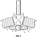
- arm members 132, 134 are movable from a first position in which arm member 132, 134 are retracted, substantially in alignment with longitudinal axis "A-A" as shown in FIG. 1 to a second position in which arm members 132, 134 are deployed, defining a transverse axis "B-B" as shown in FIG. 2 or an acute angle with respect to the longitudinal axis "A-A,” for example.
- trajectory guide 120 includes a generally tapered configuration to facilitate insertion/removal thereof into an opening in tissue "T.”
- Trajectory guide 120 defines bores 122, 124 (shown in phantom for illustrative purposes) that extend obliquely from a proximal end portion thereof to a distal end portion thereof, thereby forming an angle with respect to longitudinal axis "A-A.”
- Bores 122, 124 define longitudinal axes "D-D,” “E-E,” respectively.
- Bores 122, 124 may be dimensioned to receive one or more types of surgical instruments, e.g., surgical instruments configured to manipulate a suture.
- each bore 122, 124 with respect to longitudinal axis "A-A” may be tailored to meet the needs of a particular procedure such that bores 122, 124 in conjunction with introducer guard member 130 provide proper configuration for suture "S” to pierce through tissue "T,” as shown in FIG. 4 .
- a greater degree of angle needs to be selected if a wider mesh 148 is to be chosen, in order to ensure that mesh 148 tightly covers against the posterior side of the opening of tissue "T.” Moreover, by choosing a greater degree of angle, suture “S” enters the posterior side of tissue “T” away from the opening in tissue “T” which may inhibit tearing of sutured tissue “T.” It is also envisioned that additional bores may be defined in trajectory guide 120 to further accommodate other surgical instruments through trajectory guide 120.
- introducer guard member 130 is operatively connected to distal end portion 112 of elongate shaft 110.
- proximal end 136 of arm member 132 is hingedly coupled to distal end portion 112 of elongate shaft 110 such that arm member 132 can be hingedly retracted, substantially in alignment with longitudinal axis "A-A" in order to facilitate insertion/removal of introducer guard member 130 through the opening of tissue "T.”
- a proximal end of arm member 134 is substantially similar and is not shown.
- Hingedly coupled arm members 132, 134 can also be deployed in the direction of arrows "X" shown in FIG. 1 , such that deployed arm members 132, 134 define a transverse axis "B-B.”
- deployed arm members 132, 134 are substantially orthogonal to longitudinal axis "A-A.”
- introducer guard member 130 including a pair of attaching members 144, 146 on a first surface 152 of arm members 132, 134, and more particularly, disposed adjacent free ends 140, 142 of arm members 132, 134, respectively.
- Attaching members 144, 146 may be in a form of prongs or pins configured to releasably retain the ends of suture "S,” as shown in FIGS. 4 and 4A .
- Each end of suture “S” may, for example, form a loop so that suture "S” can be releasably anchored to each of attaching members 144, 146 as shown in FIG. 4 and 4A .
- introducer guard member 130 includes a mesh 148 at least partially enclosing introducer guard member 130 when introduced into the opening in tissue "T,” as shown in FIG. 4B .
- Mesh 148 is connected to suture "S” which secures mesh 148 to introducer guard member 130 by having each end of suture "S” anchored to each of attaching members 144, 146.
- Low tack adhesive may be used on mesh 148 to releasably hold surplus suture “S” on mesh 148 such that surplus suture “S” does not interfere with the procedure being performed.
- surplus suture “S” may be housed in a pocket defined by a two-piece mesh 148a welded on the edges, as shown in FIG. 4C .
- Two-piece mesh 148a includes an upper mesh portion 149a and a lower mesh portion 149b.
- Upper mesh portion 149a defines holes 153 through which ends of suture "S” pass.
- Surplus suture "S” allows arm members 132, 34 to move from the first position to the second position without tearing suture "S” or mesh 148a.
- surplus suture "S” housed in the pocket does not interfere with the procedure being performed when arm members 132, 134 are in the first position.
- mesh 148 may be made of absorbable material and/or any suitable bio-compatible material. Mesh 148 provides prophylaxis against incisional hernia.
- a pair of cannulated needles 160, 162 each defining a lumen therethrough are provided in bores 122, 124 of trajectory guide 120.
- Cannulated needles 160, 162 are dimensioned to slidably extend through bores 122, 124 of trajectory guide 120, respectively.
- introducer guard member 130 When introducer guard member 130 is in the second position, i.e., arm members 132, 134 are deployed, longitudinal axis "D-D,” “E-E” are in alignment with attaching members 144, 146, respectively.
- Cannulated needles 160, 162 are provided to extend through bores 122, 124 and pierce through tissue "T" (e.g., a fascia of an abdominal cavity).
- Cannulated needles 160, 162 move through tissue "T” and further extend distally until reaching first surface 152 of introducer guard member 130.
- Attaching members 144, 146 that serve to releasably anchor suture “S” also serve as a cannulated needle stopper to prevent cannulated needles 160, 162 from extending beyond free ends 140, 142 of arm members 132, 134, respectively.
- a pair of rods 164, 166 each having catching structure coupled to a distal end portion thereof is provided.
- Catching structure may be, for example, a hook 170.
- other catching structure may be employed.
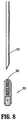
- a ferrule assembly 300 as shown in FIG. 8 , may be disposed adjacent free ends 140, 142 of arm members 132, 134, respectively.
- Ferrule assembly 300 is configured to releasably retain a ferrule 360 which is adapted to retain a portion of suture "S.”
- a distal end of a needle 350 is configured to engage ferrule 360 within ferrule assembly 300 for removal of ferrule 360 from ferrule assembly 300 along with suture "S".
- Ferrule 360 frictionally engages with open distal end of needle 350.
- needle 350 may also engage ferrule 360 through, for example, magnetic or adhesive, engagement.
- Rods 164, 166 are dimensioned to slidably extend through lumens of cannulated needles 160, 162. Rods 164, 166 that extend through lumens of cannulated needles 160, 162 are directed towards attaching members 144, 146 on first surface 152 of introducer guard member 130. By utilizing hooks 170 provided at the distal end portions of rods 164, 166, a surgeon may manipulate rods 164, 166 from a relatively remote location to capture the looped ends of suture "S" anchored to attaching members 144, 146.
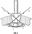
- rods 164, 166 now engaging looped ends of suture "S,” may be pulled proximally and out of trajectory guide 120, thereby disengaging looped ends of suture “S” from attaching members 144, 146 as shown FIG. 5 . Consequently, the looped ends of suture “S” are pulled out of trajectory guide 120. Thereafter, looped ends of suture “S” are disengaged from rods 164, 166 such that cannulated needles 160, 162 may be withdrawn from trajectory guide 120.
- suturing instrument 100 Upon extraction of rods 164, 166 and cannulated needles 160, 162 from trajectory guide 120, suturing instrument 100 is now ready to be removed from the opening in tissue "T” by first releasing the lock mechanism on trajectory guide 120 and retracting arm members 132, 134 of introducer guard member 130 to the first position. Thereafter, suture "S” that is connected to mesh 148 is ready to be tied to appose tissue "T,” as will be discussed in greater detail below.
- suturing device 100 Operation of suturing device 100 will now be described with reference to FIGS. 1-7 .
- mesh 148 has been secured to second surface 150 of arm members 132, 134 by suture "S" which is releasably anchored to attaching member 144, 146 of arm members 132, 134, respectively (as best seen in FIG. 4 ).
- suturing device 100 is inserted into an opening in tissue "T" created by, e.g., trocar, obturator, or the like.
- a distal portion of elongate shaft 110 is first inserted through the opening in tissue "T” and trajectory guide 120 is securely wedged into the opening in tissue "T.”
- the surgeon adjusts the distance between trajectory guide 120 and introducer guard member 130 based on the anatomy of the patient by moving trajectory guide 120 along elongate shaft 110. Once the desired distance is achieved, the locking mechanism on trajectory guide 120 is utilized to securely anchor trajectory guide 120 to a desired position along elongate shaft 110.
- trajectory guide 120 may be position in the opening in tissue "T” and move elongate shaft 110 relative to trajectory guide 120 to adjust position of introducer guard member 130.
- Trajectory guide 120 may include additional set of bores 122a, 124a, each defining longitudinal axis "K-K,” “L-L” in order to account for the change in angle when the distance between trajectory guide 120 and introducer guard member 130 is varied. It is contemplated that trajectory guide 120 may further include a plurality of bores to further accommodate a wide range of patients and procedures being performed.
- elongate shaft 110 may include indicia related to distance between trajectory guide 120 and introducer guard member 130 indicating which bores to use.
- trajectory guide 120 facilitates secure anchoring thereof to the opening in tissue "T.”
- arm members 132, 134 of introducer guard member 130 that are hingedly coupled to distal end portion 112 of elongate shaft 110 are deployed in the direction of arrow "X" shown in FIG. 1 by an actuating mechanism.
- introducer guard member 130 coupled to elongate shaft 110 may also include other linkages such as cam paths, rotating elements, etc.
- the actuating mechanism may include a pneumatic actuating mechanism or a hydraulic actuating mechanism.
- the pneumatic actuating mechanism may use pressurized gas, e.g., compressed air, carbon dioxide, or the like, to deploy arm members 132, 134 from the retracted position.
- the hydraulic actuating mechanism may use liquid, e.g., sterilized water, saline, or the like, to trigger the mechanical motion of deploying arm members 132, 134.
- the pneumatic and hydraulic actuating mechanisms may be portable or non-portable mechanisms.
- Deployed arm members 132, 134 are now oriented in a manner substantially orthogonal to longitudinal axis "A-A,” thereby defining transverse axis "B-B.” At this point, longitudinal axes of bores "D-D,” “E-E” align with attaching members 144, 146 disposed adjacent free ends 140, 142 of arm members 132, 134, respectively.
- cannulated needles 160, 162 each having lumens therethrough are slidably inserted through bores 122, 124, respectively. Bores 122, 124 that define longitudinal axes "D-D,” “E-E,” respectively, guide cannulated needles 160, 162 through tissue "T” and toward respective attaching members 144, 146. Cannulated needles 160, 162 are prevented from extending beyond free ends of arm member 140, 142 by the respective attaching members 144, 146. Upon reaching attaching member 144, 146, cannulated needles 160, 162 come in contact with first surface 152 of introducer guard member 130.
- rods 164, 166 are slidably inserted through the lumens of cannulated needles 160, 162, respectively.
- Rods 164, 166 exit cannulated needles 160, 162, adjacent attaching member 144, 146 having looped ends of suture "S” anchored thereto.
- Catching structure such as hooks 170 provided at distal end portions of rods 164, 166 are utilized to capture the looped ends of suture "S” by manipulating rods 164, 166 from a relatively remote location. Looped ends of suture "S” releasably anchored to attaching members 144, 146 are captured by hooks 170 and disengage from attaching members 144, 146.
- cannulated needles 160, 162 and rods 164, 166 are removed from trajectory guide 120 such that suture "S” now directly pierces through tissue "T.”
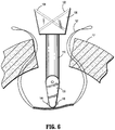
- suturing instrument 100 may be proximally pulled out of tissue "T” by first placing the arms 132, 134 in the retracted position and releasing the locking mechanism on trajectory guide 120 to permit trajectory guide 120 to be translatable along elongate shaft 110.
- Trajectory guide 120 now translatable along elongate shaft 110 is proximally translated to disengage from the opening in tissue "T.”
- elongate shaft 110 may be slightly pushed distally to provide sufficient space for arm members 132, 134 to retract to the initial position in which introducer guard member 130 is in substantial alignment with longitudinal axis "A-A.”
- trajectory guide 120 in substantial alignment with longitudinal axis "A-A” is pulled out of the opening in tissue "T” by which the looped ends of suture "S” exit bores 122, 124 from the distal end portions of trajectory guide 120.
- suturing instrument 100 is withdrawn from the opening in tissue "T,” while leaving suture “S” containing mesh 148 and directly piercing tissue "T” in place.
- suture "S” having mesh 148 remains in place with respect to tissue “T” and is now ready to be tied to appose tissue “T,” as will be discussed in greater detail below.
- the degree of angle of bores 122, 124 with respect to longitudinal axis "A-A” and the length of arm members 132, 134 may be tailored to meet the suitable needs of the procedure being performed.
- a greater degree of angle needs to be selected if a bigger mesh 148 is to be chosen, in order to ensure that mesh 148 tightly covers against the posterior side of the opening of tissue "T.”
- suture "S” enters the posterior side of tissue “T” away from the opening in tissue “T” which may inhibit tearing of sutured tissue “T.”
- the looped ends of suture “S” are now tied together to appose tissue "T,” while providing mesh 148 to the second surface of tissue "T.”
- an actuator assembly 500 as shown in FIG. 9 may be used with suturing device 100 of the present disclosure to actuate arm members 132, 134 from the first position to the second position or vice versa.
- Actuator assembly 500 includes a knob 540 and a base assembly 560. Knob 540 and base assembly 560 are coupled by elongate shaft 110. Base 560 defines a bore 561 in which a biasing member 562 is housed in longitudinal alignment with shaft 110. Arm members 532, 534 are hingedly coupled to an engaging portion 536 of base 560 about pivots 535a, 535b, respectively.
- Each arm member 532, 534 defines a slot 537 for slidably accommodating therein pin 538 protruding transversely from shaft 110 (only slot 537 defined in arm member 534 is shown in FIG. 9 ).
- pin 538 of shaft 110 translates distally with respect to engaging portion 536 of base 560, and slots 537 urge respective arm members 532, 534 to the retracted position (first position).
- arm members 532, 534 are longitudinally aligned with shaft 110 and are ready to be inserted into the opening in tissue "T.”
- a locking mechanism may be provided to lock arm members 532, 534 in the first position.
- biasing member 562 moves shaft 110 proximally with respect to engaging portion 536 of base 560 such that pin 538 translates proximally, which in turn urges arm members 532, 534 to be deployed to the second position, as shown in FIG. 9 .
- Mesh 148 can also be attached to arm members 532, 534 by suture "S.” As discussed above, attaching members 144, 146 in a form of prongs or pins configured to releasably retain the ends of suture "S" may be provided on arm members 532, 534.
Description
- The present disclosure relates to a wound closure device and, more particularly, to a wound closure device for suturing an opening in tissue.
- During endoscopic surgical procedures, for example, a trocar device is utilized to puncture the peritoneum to provide an access port by way of a cannula through the abdominal wall. Generally, a trocar and/or cannula is placed through the abdominal wall for introduction of surgical instrumentation which is necessary to carry out the surgical procedure. In this manner, the surgeon may introduce a surgical instrument such as a grasper, scissor, clip applier, stapler or any other surgical instrument which may be necessary during the particular surgical procedure. Once the procedure is complete, it is necessary to close the wound.
- Conventional instruments for closing puncture wounds generally include a shaft that can be extended into the body through either the puncture wound itself (in the case of a puncture caused by trauma) or through a cannula (in the case of a puncture created to access a surgical site). Suture retaining needles are then deployed from the shaft into tissue. Unfortunately, the mechanisms used for deploying the needles are often cumbersome and may make the extension and/or retraction of the suturing device difficult.
-
- The aspects and embodiments of the present invention are set forth in the claims.
- Further embodiments of the disclosure not according to the invention but useful to the understanding of the invention are disclosed. In accordance with the present invention, a suturing device is provided. The suturing device includes an elongate shaft defining a longitudinal axis, a trajectory guide mounted on the elongate shaft and an introducer guard member operatively coupled to the elongate shaft. The trajectory guide defines at least one bore therethrough. The introducer guard member includes at least one arm member that is movable between a first position in which the arm member is retracted, substantially in alignment with the longitudinal axis and a second position in which the at least one arm member is deployed, defining an angle with respect to the longitudinal axis.
- In an embodiment, the arm member is hingedly connected to the elongate shaft. In particular, the arm member may be hingedly connected to a distal portion of the elongate shaft.
- According to the invention, the trajectory guide is translatable along the elongate shaft. The trajectory guide may include a locking mechanism for securely anchoring the trajectory guide to a position along the elongate shaft. The bore defined in the trajectory guide obliquely extends therein with respect to the longitudinal axis.
- According to the invention, the arm member includes an attaching member configured for releasably retaining a suture. The attaching member may be on a first surface of the arm member. The bore is aligned with the attaching member when the arm member is in the second position.
- The attaching member may be disposed adjacent a distal end of the arm member. The bore is aligned with the attaching member when the arm member is in the second position.
- In another embodiment, the suturing device further includes a mesh disposed on a second surface of the arm member when the arm member is in the second position. The suture attaches the mesh against the second surface of the arm member when the arm member is in the second position.
- In still another embodiment, the suturing device further includes a cannulated needle defining a lumen therethrough. The bore of the trajectory guide is dimensioned for receiving the cannulated needle therethrough. The suturing device may further include a rod. The lumen of the cannulated needle is configured for receiving the rod therethrough. The rod may include catching structure for capturing the suture releasably retained by the attaching member. The catching structure is disposed at a distal portion of the rod. The catching structure may be a hook.
- In still another embodiment, the introducer guard member in the second position is substantially orthogonal with respect to the longitudinal axis.
- In still another embodiment, the trajectory guide is longitudinally tapered with respect to a width thereof.
- In an alternative embodiment, the introducer guard member is longitudinally tapered with respect to a width thereof. Moreover, the arm member may be longitudinally tapered with respect to a width thereof.
- Various embodiments of the presently disclosed suturing instrument are described herein with references to the accompanying drawings, wherein:
-
FIG. 1 is a side view of a suturing device in accordance with the present disclosure disposed in an opening in tissue; -
FIG. 2 is a side view of the suturing device ofFIG. 1 illustrating an introducer guard member thereof in a deployed state; -
FIG. 3 is a side view of the suturing device ofFIG. 2 having a pair of cannulated needles inserted through a trajectory guide of the suturing device; -
FIG. 4 is a side view of the suturing device ofFIG. 3 having a pair of rods inserted through the pair of cannulated needles; -
FIG. 4A is an enlarged view of the indicated area of detail ofFIG. 4 ; -
FIG. 4B is a side view of the suturing device ofFIG. 1 illustrating a mesh attached to the introducer guard member in a retracted state; -
FIG. 4C is a perspective view of a two-piece mesh with parts separated; -
FIG. 5 is a side view of the suturing device ofFIG. 4 illustrating extraction of looped ends of a suture; -
FIG. 6 is a side view of the suturing device ofFIG. 5 illustrating extraction of the suturing device from an opening of tissue; -
FIG. 7 is a cross-sectional view of tissue ofFIG. 6 apposed by the suture; -
FIG. 8 is a side view of a ferrule assembly for use with the suturing device ofFIG. 1 ; and -
FIG. 9 is a side view of an actuation device for use with the suturing device ofFIG. 1 - Various exemplary embodiments of the presently disclosed surgical device will now be described in detail with reference to the drawings wherein like reference numerals identify similar or identical elements. In the drawings and in the description which follows, the term "proximal" will refer to the end of the component that is closer to the operator during use, while the term "distal" will refer to the end of the component that is farther from the operator, as is traditional and conventional in the art.
- With reference to
FIGS. 1 and2 , asuturing instrument 100 generally includes anelongate shaft 110 defining a longitudinal axis "A-A," atrajectory guide 120 translatably mounted onelongate shaft 110, and anintroducer guard member 130 operatively coupled to adistal end portion 112 ofelongate shaft 110.Trajectory guide 120 is translatably mounted onelongate shaft 110 and includes a locking mechanism (not shown) that securely anchorstrajectory guide 120 to a desired position alongelongate shaft 110. Thus, the distance betweentrajectory guide 120 and introducerguard member 130 may be adjusted based on the anatomy of the patient.Introducer guard member 130 includes a pair ofarm members arm members arm member FIG. 1 to a second position in which armmembers FIG. 2 or an acute angle with respect to the longitudinal axis "A-A," for example. - With continued reference to
FIGS. 1 and2 ,trajectory guide 120 includes a generally tapered configuration to facilitate insertion/removal thereof into an opening in tissue "T."Trajectory guide 120 definesbores 122, 124 (shown in phantom for illustrative purposes) that extend obliquely from a proximal end portion thereof to a distal end portion thereof, thereby forming an angle with respect to longitudinal axis "A-A."Bores Bores bore introducer guard member 130 provide proper configuration for suture "S" to pierce through tissue "T," as shown inFIG. 4 . For example, a greater degree of angle needs to be selected if awider mesh 148 is to be chosen, in order to ensure thatmesh 148 tightly covers against the posterior side of the opening of tissue "T." Moreover, by choosing a greater degree of angle, suture "S" enters the posterior side of tissue "T" away from the opening in tissue "T" which may inhibit tearing of sutured tissue "T." It is also envisioned that additional bores may be defined intrajectory guide 120 to further accommodate other surgical instruments throughtrajectory guide 120. - With continued reference to
FIGS. 1 and2 ,introducer guard member 130 is operatively connected todistal end portion 112 ofelongate shaft 110. In the illustrated embodiment,proximal end 136 ofarm member 132 is hingedly coupled todistal end portion 112 ofelongate shaft 110 such thatarm member 132 can be hingedly retracted, substantially in alignment with longitudinal axis "A-A" in order to facilitate insertion/removal ofintroducer guard member 130 through the opening of tissue "T." A proximal end ofarm member 134 is substantially similar and is not shown. Hingedly coupledarm members FIG. 1 , such that deployedarm members FIG. 2 , deployedarm members - With reference now to
FIGS. 3-5 , there is illustratedintroducer guard member 130 including a pair of attachingmembers first surface 152 ofarm members arm members members FIGS. 4 and 4A . Each end of suture "S" may, for example, form a loop so that suture "S" can be releasably anchored to each of attachingmembers FIG. 4 and 4A . In the alternative, a slit dimensioned to secure or wedge a portion of suture "S" to free ends 140, 142 ofarm members arm members introducer guard member 130 includes amesh 148 at least partially enclosingintroducer guard member 130 when introduced into the opening in tissue "T," as shown inFIG. 4B .Mesh 148 is connected to suture "S" which securesmesh 148 tointroducer guard member 130 by having each end of suture "S" anchored to each of attachingmembers mesh 148 to releasably hold surplus suture "S" onmesh 148 such that surplus suture "S" does not interfere with the procedure being performed. Alternatively, surplus suture "S" may be housed in a pocket defined by a two-piece mesh 148a welded on the edges, as shown inFIG. 4C . Two-piece mesh 148a includes anupper mesh portion 149a and alower mesh portion 149b.Upper mesh portion 149a definesholes 153 through which ends of suture "S" pass. Surplus suture "S" allowsarm members 132, 34 to move from the first position to the second position without tearing suture "S" ormesh 148a. As such, surplus suture "S" housed in the pocket does not interfere with the procedure being performed whenarm members - As
arm members mesh 148 andmesh 148 becomes disposed on asecond surface 150 ofintroducer guard member 130 as shown inFIG. 4 . Mesh 148 may be made of absorbable material and/or any suitable bio-compatible material.Mesh 148 provides prophylaxis against incisional hernia. - In the embodiment illustrated in
FIGS. 3-5 , a pair of cannulatedneedles bores trajectory guide 120. Cannulated needles 160, 162 are dimensioned to slidably extend throughbores trajectory guide 120, respectively. Whenintroducer guard member 130 is in the second position, i.e.,arm members members bores first surface 152 ofintroducer guard member 130. Attachingmembers needles arm members - With particular reference to
FIG. 4 , a pair ofrods hook 170. However, other catching structure may be employed. For example, aferrule assembly 300, as shown inFIG. 8 , may be disposed adjacent free ends 140, 142 ofarm members Ferrule assembly 300 is configured to releasably retain aferrule 360 which is adapted to retain a portion of suture "S." A distal end of aneedle 350 is configured to engageferrule 360 withinferrule assembly 300 for removal offerrule 360 fromferrule assembly 300 along with suture "S".Ferrule 360 frictionally engages with open distal end ofneedle 350. However, it is further contemplated thatneedle 350 may also engageferrule 360 through, for example, magnetic or adhesive, engagement. -
Rods needles Rods needles members first surface 152 ofintroducer guard member 130. By utilizinghooks 170 provided at the distal end portions ofrods rods members rods trajectory guide 120, thereby disengaging looped ends of suture "S" from attachingmembers FIG. 5 . Consequently, the looped ends of suture "S" are pulled out oftrajectory guide 120. Thereafter, looped ends of suture "S" are disengaged fromrods trajectory guide 120. Upon extraction ofrods needles trajectory guide 120, suturinginstrument 100 is now ready to be removed from the opening in tissue "T" by first releasing the lock mechanism ontrajectory guide 120 and retractingarm members introducer guard member 130 to the first position. Thereafter, suture "S" that is connected to mesh 148 is ready to be tied to appose tissue "T," as will be discussed in greater detail below. - Operation of
suturing device 100 will now be described with reference toFIGS. 1-7 . In the description that follows, it is assumed thatsuturing device 100 is in the ready-to-use condition. Specifically,mesh 148 has been secured tosecond surface 150 ofarm members member arm members FIG. 4 ). - Initially, with
introducer guard member 130 in a retracted position, substantially in alignment with longitudinal axis "A-A" ofelongate shaft 110,suturing device 100 is inserted into an opening in tissue "T" created by, e.g., trocar, obturator, or the like. A distal portion ofelongate shaft 110 is first inserted through the opening in tissue "T" andtrajectory guide 120 is securely wedged into the opening in tissue "T." The surgeon adjusts the distance betweentrajectory guide 120 andintroducer guard member 130 based on the anatomy of the patient by movingtrajectory guide 120 alongelongate shaft 110. Once the desired distance is achieved, the locking mechanism ontrajectory guide 120 is utilized to securely anchortrajectory guide 120 to a desired position alongelongate shaft 110. Alternatively, the surgeon may positiontrajectory guide 120 in the opening in tissue "T" and moveelongate shaft 110 relative to trajectory guide 120 to adjust position ofintroducer guard member 130.Trajectory guide 120, as shown inFIG. 4B , may include additional set ofbores trajectory guide 120 andintroducer guard member 130 is varied. It is contemplated thattrajectory guide 120 may further include a plurality of bores to further accommodate a wide range of patients and procedures being performed. Moreover,elongate shaft 110 may include indicia related to distance betweentrajectory guide 120 andintroducer guard member 130 indicating which bores to use. The tapered configuration oftrajectory guide 120 facilitates secure anchoring thereof to the opening in tissue "T." Upon anchoringtrajectory guide 120 to the opening in tissue "T,"arm members introducer guard member 130 that are hingedly coupled todistal end portion 112 ofelongate shaft 110 are deployed in the direction of arrow "X" shown inFIG. 1 by an actuating mechanism. It is also contemplated thatintroducer guard member 130 coupled toelongate shaft 110 may also include other linkages such as cam paths, rotating elements, etc. - The actuating mechanism may include a pneumatic actuating mechanism or a hydraulic actuating mechanism. The pneumatic actuating mechanism may use pressurized gas, e.g., compressed air, carbon dioxide, or the like, to deploy
arm members arm members - Deployed
arm members members arm members - With reference to
FIG. 3 , cannulatedneedles bores Bores needles members arm member members member needles first surface 152 ofintroducer guard member 130. - With reference to
FIG. 4 , upon placing cannulatedneedles first surface 152 ofarm members rods needles Rods needles member hooks 170 provided at distal end portions ofrods rods members hooks 170 and disengage from attachingmembers - With reference to
FIG. 5 , the looped ends of suture "S" now disengaged from attachingmembers needles bores trajectory guide 120. Following the extraction of the looped ends of suture "S," cannulated needles 160, 162 androds trajectory guide 120 such that suture "S" now directly pierces through tissue "T." Upon removal of cannulatedneedles suturing instrument 100 may be proximally pulled out of tissue "T" by first placing thearms trajectory guide 120 to permittrajectory guide 120 to be translatable alongelongate shaft 110.Trajectory guide 120 now translatable alongelongate shaft 110 is proximally translated to disengage from the opening in tissue "T." At the same time,elongate shaft 110 may be slightly pushed distally to provide sufficient space forarm members introducer guard member 130 is in substantial alignment with longitudinal axis "A-A." As shown inFIG. 6 ,trajectory guide 120 in substantial alignment with longitudinal axis "A-A" is pulled out of the opening in tissue "T" by which the looped ends of suture "S" exit bores 122, 124 from the distal end portions oftrajectory guide 120. At this time, suturinginstrument 100 is withdrawn from the opening in tissue "T," while leaving suture "S" containingmesh 148 and directly piercing tissue "T" in place. - After the removal of
suturing instrument 100 from the opening of tissue "T," suture "S" havingmesh 148 remains in place with respect to tissue "T" and is now ready to be tied to appose tissue "T," as will be discussed in greater detail below. As discussed above, the degree of angle ofbores arm members bigger mesh 148 is to be chosen, in order to ensure thatmesh 148 tightly covers against the posterior side of the opening of tissue "T." Moreover, by choosing a greater degree of angle, suture "S" enters the posterior side of tissue "T" away from the opening in tissue "T" which may inhibit tearing of sutured tissue "T." With reference toFIG. 7 , the looped ends of suture "S" are now tied together to appose tissue "T," while providingmesh 148 to the second surface of tissue "T." - It is contemplated that an
actuator assembly 500 as shown inFIG. 9 may be used withsuturing device 100 of the present disclosure to actuatearm members Actuator assembly 500 includes aknob 540 and abase assembly 560.Knob 540 andbase assembly 560 are coupled byelongate shaft 110.Base 560 defines abore 561 in which a biasingmember 562 is housed in longitudinal alignment withshaft 110.Arm members portion 536 ofbase 560 aboutpivots arm member slot 537 for slidably accommodating therein pin 538 protruding transversely from shaft 110 (only slot 537 defined inarm member 534 is shown inFIG. 9 ). Asknob 540 is pressed distally by the operator, pin 538 ofshaft 110 translates distally with respect to engagingportion 536 ofbase 560, andslots 537 urgerespective arm members arm members shaft 110 and are ready to be inserted into the opening in tissue "T." It is further contemplated that a locking mechanism (not shown) may be provided to lockarm members knob 540 by the operator, biasingmember 562 movesshaft 110 proximally with respect to engagingportion 536 ofbase 560 such thatpin 538 translates proximally, which in turn urgesarm members FIG. 9 . Mesh 148 can also be attached to armmembers members arm members - From the foregoing and with reference to the various figure drawings, those skilled in the art will appreciate that certain modifications can also be made to the present disclosure without departing from the scope of the same. While several embodiments of the disclosure have been shown in the drawings, it is not intended that the disclosure be limited thereto, as it is intended that the disclosure be as broad in scope as the art will allow and that the specification be read likewise. Therefore, the above description should not be construed as limiting, but merely as exemplifications of particular embodiments. Those skilled in the art will envision other modifications within the scope of the claims appended hereto.
Claims (17)
- A suturing device (100) comprising:an elongate shaft (110) defining a longitudinal axis;a trajectory guide (120) mounted on the elongate shaft (110), the trajectory guide (120) defining at least one bore (122, 124) therethrough dimensioned to receive one surgical instrument configured to manipulate a suture, wherein the at least one bore (122, 124) obliquely extends in the trajectory guide (120) with respect to the longitudinal axis and wherein the trajectory guide (120) is, during use, positioned in an opening in tissue;an introducer guard member (130) operatively coupled to the elongate shaft (110), the introducer guard member (130) including at least one arm member (132, 134), the at least one arm member being movable between a first position in which the arm member (132, 134) is retracted, substantially in alignment with the longitudinal axis and a second position in which the at least one arm member (132, 134) is deployed, defining an angle with respect to the longitudinal axis, the at least one arm member (132, 134) including an attaching member (144, 146) configured for releasably retaining a suture; andwherein the at least one bore (122, 124) is aligned with the attaching member (144, 146) when the at least one arm member (132, 134) is in the second position and the trajectory guide (120) is positioned in the opening in tissue;characterised in thatthe trajectory guide (120) is translatable along the elongate shaft (110).
- The suturing device (100) of claim 1, wherein the at least one arm member (132, 134) is hingedly connected to the elongate shaft (110).
- The suturing device (100) of claim 1, wherein the at least one arm member (132, 134) is hingedly connected to a distal portion of the elongate shaft (110).
- The suturing device (100) of any of claims 1 to 3, wherein the trajectory guide (120) includes a locking mechanism for securely anchoring the trajectory guide (120) to a position along the elongate shaft (110).
- The suturing device (100) of claim 1, wherein the attaching member (144, 146) is on a first surface (152) of the at least one arm member (132, 134).
- The suturing device (100) of claim 1, wherein the attaching member (144, 146) is disposed adjacent a distal end of the at least one arm member (132, 134).
- The suturing device (100) of claim 1 or claim 6, wherein the at least one bore (122, 124) is aligned with the attaching member (144, 146) when the at least one arm member (132, 134) is in the second position.
- The suturing device (100) of claim 7, further comprising a mesh (148) disposed on a second surface (150) of the at least one arm member (132, 134) when the at least one arm member (132, 134) is in the second position.
- The suturing device (100) of claim 8, wherein the suture attaches the mesh (148) against the second surface (150) of the at least one arm member (132, 134) when the at least one arm member (132, 134) is in the second position.
- The suturing device (100) of any preceding claim, further comprising a cannulated needle (160, 162) defining a lumen therethrough, wherein the at least one bore (122, 124) of the trajectory guide (120) is dimensioned for receiving the cannulated needle (160, 162) therethrough.
- The suturing device (100) of claim 10, further comprising a rod (164, 166), the lumen of the cannulated needle (160, 162) being configured for receiving the rod (164, 166) therethrough.
- The suturing device (100) of claim 11, wherein the rod (164, 166) includes catching structure for capturing the suture releasably retained by the attaching member (144, 146).
- The suturing device (100) of claim 12, wherein the catching structure is disposed at a distal portion of the rod (164, 166).
- The suturing device (100) of claim 12 or claim 13, wherein the catching structure is a hook (170).
- The suturing device (100) of any preceding claim, wherein the introducer guard member (130) in the second position is substantially orthogonal with respect to the longitudinal axis.
- The suturing device (100) of any preceding claim, wherein the trajectory guide (120) is longitudinally tapered with respect to a width thereof oriented with respect to the longitudinal axis of the trajectory guide (120); and/or wherein the introducer guard member (130) is longitudinally tapered with respect to a width thereof oriented with respect to the longitudinal axis of the trajectory guide (120).
- The suturing device (100) of any preceding claim, wherein the at least one arm member (132, 134) is longitudinally tapered with respect to a width thereof oriented with respect to the longitudinal axis of the trajectory guide (120).
Applications Claiming Priority (2)
| Application Number | Priority Date | Filing Date | Title |
|---|---|---|---|
| US36881510P | 2010-07-29 | 2010-07-29 | |
| US13/117,317 US8906042B2 (en) | 2010-07-29 | 2011-05-27 | Wound closure device including mesh barrier |
Publications (2)
| Publication Number | Publication Date |
|---|---|
| EP2412317A1 EP2412317A1 (en) | 2012-02-01 |
| EP2412317B1 true EP2412317B1 (en) | 2019-07-17 |
Family
ID=44510819
Family Applications (1)
| Application Number | Title | Priority Date | Filing Date |
|---|---|---|---|
| EP11250682.9A Active EP2412317B1 (en) | 2010-07-29 | 2011-07-28 | Wound closure device |
Country Status (5)
| Country | Link |
|---|---|
| US (2) | US8906042B2 (en) |
| EP (1) | EP2412317B1 (en) |
| JP (1) | JP2012030067A (en) |
| AU (1) | AU2011202923A1 (en) |
| CA (1) | CA2742457A1 (en) |
Cited By (1)
| Publication number | Priority date | Publication date | Assignee | Title |
|---|---|---|---|---|
| EP4190246A1 (en) | 2021-12-06 | 2023-06-07 | Universität Zürich | Device for closing a tissue opening |
Families Citing this family (47)
| Publication number | Priority date | Publication date | Assignee | Title |
|---|---|---|---|---|
| US7662161B2 (en) | 1999-09-13 | 2010-02-16 | Rex Medical, L.P | Vascular hole closure device |
| US8906059B2 (en) | 2007-07-13 | 2014-12-09 | Rex Medical, L.P. | Vascular hole closure device |
| US20110029013A1 (en) | 2008-02-15 | 2011-02-03 | Mcguckin James F | Vascular Hole Closure Device |
| US8070772B2 (en) | 2008-02-15 | 2011-12-06 | Rex Medical, L.P. | Vascular hole closure device |
| US8491629B2 (en) | 2008-02-15 | 2013-07-23 | Rex Medical | Vascular hole closure delivery device |
| US8920462B2 (en) | 2008-02-15 | 2014-12-30 | Rex Medical, L.P. | Vascular hole closure device |
| US9226738B2 (en) | 2008-02-15 | 2016-01-05 | Rex Medical, L.P. | Vascular hole closure delivery device |
| US8920463B2 (en) | 2008-02-15 | 2014-12-30 | Rex Medical, L.P. | Vascular hole closure device |
| EP2385798B1 (en) | 2009-01-12 | 2019-07-03 | Teleflex Medical Incorporated | Apparatus for tissue closure |
| US8906042B2 (en) * | 2010-07-29 | 2014-12-09 | Covidien Lp | Wound closure device including mesh barrier |
| KR101082762B1 (en) * | 2011-02-18 | 2011-11-10 | 이정삼 | Retractor system for laparoscopic surgery |
| AU2012202202B2 (en) * | 2011-07-20 | 2017-05-11 | Rex Medical, L.P. | Vascular hole closure delivery device |
| US8979747B2 (en) | 2011-09-23 | 2015-03-17 | Cooper Surgicalk, Inc. | Endoscopic ports and related kits and methods |
| US9149272B2 (en) * | 2011-12-27 | 2015-10-06 | Coopersurgical, Inc. | Suture passer guides and related kits and methods |
| WO2013103682A2 (en) * | 2012-01-04 | 2013-07-11 | Teleflex Medical Incorporated | Apparatus and methods for tissue closure |
| US9668727B2 (en) | 2012-03-13 | 2017-06-06 | Suture Ease, Inc. | Needle and snare guide apparatus for passing suture |
| EP2825101A4 (en) * | 2012-03-13 | 2015-12-16 | Suture Ease Llc | Needle and snare guide apparatus for passing suture |
| WO2013158742A2 (en) * | 2012-04-18 | 2013-10-24 | Cook Biotech Incorporated | Surgical grafts, and implements for delivering same |
| US9066717B2 (en) | 2012-05-18 | 2015-06-30 | Coopersurgical, Inc. | Suture passer guides and related kits and methods |
| EP3038538B1 (en) * | 2013-06-19 | 2018-11-14 | Endolutions, LLC | Apparatus for fascial closure device for laparoscopic trocar port site and surgery |
| US9510823B2 (en) | 2013-08-02 | 2016-12-06 | Covidien Lp | Devices, systems, and methods for wound closure |
| US10070851B2 (en) | 2013-08-02 | 2018-09-11 | Covidien Lp | Devices, systems, and methods for wound closure |
| US9848879B2 (en) | 2013-08-02 | 2017-12-26 | Covidien Lp | Devices, systems, and methods for wound closure |
| US10201346B2 (en) | 2013-08-02 | 2019-02-12 | Covidien Lp | Devices, systems, and methods for providing surgical access and facilitating closure of surgical access openings |
| US10307144B2 (en) * | 2014-02-07 | 2019-06-04 | Medeon Biodesign, Inc. | Suture delivery device for suturing tissue |
| US10327761B2 (en) | 2014-02-07 | 2019-06-25 | Medeon Biodesign, Inc. | Suture delivery device for suturing tissue |
| KR101591056B1 (en) * | 2014-11-21 | 2016-02-18 | 김기성 | sewing cotton for laparoscopic port site closure device |
| US10299785B2 (en) | 2016-04-01 | 2019-05-28 | Ethicon Llc | Surgical access devices with integrated wound closure features |
| US11026676B2 (en) | 2017-02-06 | 2021-06-08 | Covidien Lp | Surgical wound closure apparatus |
| US10869690B2 (en) | 2017-06-29 | 2020-12-22 | Ethicon Llc | Trocar obturator with transverse needle ports |
| US10709440B2 (en) | 2017-06-29 | 2020-07-14 | Ethicon Llc | Suture passing instrument with puncture site identification feature |
| US10709473B2 (en) | 2017-06-29 | 2020-07-14 | Ethicon Llc | Trocar obturator with detachable rotary tissue fastener |
| US10485580B2 (en) | 2017-06-29 | 2019-11-26 | Ethicon Llc | Trocar with oblique needle insertion port and coplanar stopcock |
| US10639029B2 (en) | 2017-06-29 | 2020-05-05 | Ethicon Llc | Suture grasping instrument |
| US10939937B2 (en) | 2017-06-29 | 2021-03-09 | Ethicon Llc | Trocar with oblique needle insertion port and perpendicular seal latch |
| US11389192B2 (en) | 2017-06-29 | 2022-07-19 | Cilag Gmbh International | Method of suturing a trocar path incision |
| US10675018B2 (en) | 2017-06-29 | 2020-06-09 | Ethicon Llc | Needle guide instrument with transverse suture capture feature |
| US10639068B2 (en) | 2017-06-29 | 2020-05-05 | Ethicon Llc | Trocar with oblique needle insertion port and perpendicular seal latch |
| US10568619B2 (en) | 2017-06-29 | 2020-02-25 | Ethicon Llc | Surgical port with wound closure channels |
| US11129609B2 (en) | 2018-04-24 | 2021-09-28 | Covidien Lp | Devices, systems, and methods for providing surgical access and facilitating closure of surgical access openings |
| US11213288B2 (en) | 2018-05-02 | 2022-01-04 | Covidien Lp | Port site closure instrument |
| US11234690B2 (en) | 2018-05-02 | 2022-02-01 | Covidien Lp | Method and device for closing a port site incision |
| CN111374722A (en) * | 2018-12-29 | 2020-07-07 | 江苏风和医疗器材股份有限公司 | Suture assembly, puncture core assembly with suture assembly and puncture device |
| US11504105B2 (en) | 2019-01-25 | 2022-11-22 | Rex Medical L.P. | Vascular hole closure device |
| CN111096769A (en) * | 2019-12-31 | 2020-05-05 | 清华大学 | Auxiliary suturing device for hollow viscera |
| EP4259009A1 (en) * | 2020-12-11 | 2023-10-18 | Neurofine Corp. | Vessel closure devices and methods |
| USD1002009S1 (en) | 2021-08-31 | 2023-10-17 | New Wave Endo-Surgical Corp. | Medical device |
Family Cites Families (42)
| Publication number | Priority date | Publication date | Assignee | Title |
|---|---|---|---|---|
| US4007743A (en) | 1975-10-20 | 1977-02-15 | American Hospital Supply Corporation | Opening mechanism for umbrella-like intravascular shunt defect closure device |
| US4733664A (en) | 1983-12-01 | 1988-03-29 | University Of New Mexico | Surgical clip, applier, and method |
| US6036699A (en) * | 1992-12-10 | 2000-03-14 | Perclose, Inc. | Device and method for suturing tissue |
| US5507755A (en) * | 1993-08-03 | 1996-04-16 | Origin Medsystems, Inc. | Apparatus and method for closing puncture wounds |
| US5397332A (en) * | 1993-09-02 | 1995-03-14 | Ethicon, Inc. | Surgical mesh applicator |
| US5470338A (en) | 1993-10-08 | 1995-11-28 | United States Surgical Corporation | Instrument for closing trocar puncture wounds |
| US6117144A (en) * | 1995-08-24 | 2000-09-12 | Sutura, Inc. | Suturing device and method for sealing an opening in a blood vessel or other biological structure |
| JP3912620B2 (en) | 1996-05-10 | 2007-05-09 | カール シュトルツ ゲーエムベーハー ウント コー | Suture assist device |
| US6024748A (en) | 1996-07-23 | 2000-02-15 | United States Surgical Corporation | Singleshot anastomosis instrument with detachable loading unit and method |
| US7235087B2 (en) | 1999-03-04 | 2007-06-26 | Abbott Park | Articulating suturing device and method |
| US7842048B2 (en) | 2006-08-18 | 2010-11-30 | Abbott Laboratories | Articulating suture device and method |
| US8137364B2 (en) | 2003-09-11 | 2012-03-20 | Abbott Laboratories | Articulating suturing device and method |
| US7226467B2 (en) | 1999-04-09 | 2007-06-05 | Evalve, Inc. | Fixation device delivery catheter, systems and methods of use |
| US6911032B2 (en) | 1999-11-18 | 2005-06-28 | Scimed Life Systems, Inc. | Apparatus and method for compressing body tissue |
| US7083628B2 (en) | 2002-09-03 | 2006-08-01 | Edwards Lifesciences Corporation | Single catheter mitral valve repair device and method for use |
| WO2001095809A1 (en) | 2000-06-14 | 2001-12-20 | Sterilis, Inc. | Suturing method and apparatus |
| US6551330B1 (en) | 2000-09-21 | 2003-04-22 | Opus Medical, Inc. | Linear suturing apparatus and methods |
| US20090143808A1 (en) | 2001-04-24 | 2009-06-04 | Houser Russell A | Guided Tissue Cutting Device, Method of Use and Kits Therefor |
| US6776784B2 (en) | 2001-09-06 | 2004-08-17 | Core Medical, Inc. | Clip apparatus for closing septal defects and methods of use |
| US6743241B2 (en) | 2002-03-01 | 2004-06-01 | Intellimed Surgical Solutions Llc | Laparoscopic port site fascial closure device |
| JP3890589B2 (en) | 2002-04-15 | 2007-03-07 | ニプロ株式会社 | Intracardiac suture device |
| US7160309B2 (en) | 2002-12-31 | 2007-01-09 | Laveille Kao Voss | Systems for anchoring a medical device in a body lumen |
| US7449024B2 (en) | 2003-12-23 | 2008-11-11 | Abbott Laboratories | Suturing device with split arm and method of suturing tissue |
| US7211093B2 (en) | 2004-01-14 | 2007-05-01 | Lsi Solutions, Inc. | Sew-right running stitch instrument |
| US20050251175A1 (en) | 2004-05-07 | 2005-11-10 | Ethicon Endo-Surgery, Inc. | Anchors for use in attachment of bladder tissues to pelvic floor tissues following a prostatectomy |
| EP1611850A1 (en) | 2004-06-28 | 2006-01-04 | Cardio Life Research S.A. | Occlusion and tight punction device for an anatomical structure |
| US8992549B2 (en) | 2004-08-05 | 2015-03-31 | Teleflex Medical Incorporated | Laparoscopic port site closure tool |
| US8172857B2 (en) | 2004-08-27 | 2012-05-08 | Davol, Inc. | Endoscopic tissue apposition device and method of use |
| US7803167B2 (en) | 2004-09-27 | 2010-09-28 | Nobles Anthony A | Handle for suturing apparatus |
| US7789890B2 (en) | 2005-03-30 | 2010-09-07 | Ethicon Endo-Surgery, Inc. | Harness and balloon catheter assembly and method for use in anastomosis procedures |
| US7645286B2 (en) * | 2005-05-20 | 2010-01-12 | Neotract, Inc. | Devices, systems and methods for retracting, lifting, compressing, supporting or repositioning tissues or anatomical structures |
| US20080033459A1 (en) | 2006-08-03 | 2008-02-07 | Surgsolutions, Llp | Suturing apparatus for closing tissue defects |
| US7947054B2 (en) | 2007-02-14 | 2011-05-24 | EasyLab Ltd. | Mesh deployment apparatus |
| US9192374B2 (en) | 2007-10-18 | 2015-11-24 | Neochord, Inc. | Minimally invasive repair of a valve leaflet in a beating heart |
| EP2385798B1 (en) | 2009-01-12 | 2019-07-03 | Teleflex Medical Incorporated | Apparatus for tissue closure |
| BRPI1006941A2 (en) | 2009-01-26 | 2016-09-27 | Synthes Gmbh | "bidirectional suture puller" |
| BRPI1008926A2 (en) | 2009-03-11 | 2019-09-24 | Synthes Gmbh | passable knot system for repairing soft tissue injuries |
| US20110082475A1 (en) | 2009-10-01 | 2011-04-07 | Tyco Healthcare Group Lp | Wound closure device including ferrule ejector system |
| US20110082480A1 (en) | 2009-10-01 | 2011-04-07 | Tyco Healthcare Group Lp | Wound closure device including pivotable claws |
| US8591529B2 (en) | 2009-10-01 | 2013-11-26 | Covidien Lp | Wound closure device including direct-driven needle |
| US8435252B2 (en) | 2009-11-11 | 2013-05-07 | Covidien Lp | Wound closure device |
| US8906042B2 (en) * | 2010-07-29 | 2014-12-09 | Covidien Lp | Wound closure device including mesh barrier |
-
2011
- 2011-05-27 US US13/117,317 patent/US8906042B2/en active Active
- 2011-06-08 CA CA2742457A patent/CA2742457A1/en not_active Abandoned
- 2011-06-17 AU AU2011202923A patent/AU2011202923A1/en not_active Abandoned
- 2011-07-08 JP JP2011152263A patent/JP2012030067A/en not_active Ceased
- 2011-07-28 EP EP11250682.9A patent/EP2412317B1/en active Active
-
2014
- 2014-12-09 US US14/563,667 patent/US9687226B2/en active Active
Non-Patent Citations (1)
| Title |
|---|
| None * |
Cited By (2)
| Publication number | Priority date | Publication date | Assignee | Title |
|---|---|---|---|---|
| EP4190246A1 (en) | 2021-12-06 | 2023-06-07 | Universität Zürich | Device for closing a tissue opening |
| WO2023104486A1 (en) | 2021-12-06 | 2023-06-15 | Universität Zürich | Device for closing a tissue opening |
Also Published As
| Publication number | Publication date |
|---|---|
| US20120029532A1 (en) | 2012-02-02 |
| US9687226B2 (en) | 2017-06-27 |
| US20150094741A1 (en) | 2015-04-02 |
| JP2012030067A (en) | 2012-02-16 |
| CA2742457A1 (en) | 2012-01-29 |
| US8906042B2 (en) | 2014-12-09 |
| AU2011202923A1 (en) | 2012-02-16 |
| EP2412317A1 (en) | 2012-02-01 |
Similar Documents
| Publication | Publication Date | Title |
|---|---|---|
| EP2412317B1 (en) | Wound closure device | |
| US10631855B2 (en) | Wound closure device including direct-driven needle | |
| US6743241B2 (en) | Laparoscopic port site fascial closure device | |
| CN110368046B (en) | Laparoscopic fascia closure system | |
| EP2011441B1 (en) | Suturing device for sealing an opening in a blood vessel or other biological structure | |
| EP2305129A2 (en) | Wound closure device including ferrule ejector systeme | |
| EP2800521B1 (en) | Apparatus for tissue closure | |
| US20090082787A1 (en) | Suturing Device | |
| US20110082473A1 (en) | Wound closure device including releasable barbs | |
| JP6158206B2 (en) | Suture device | |
| US10463363B2 (en) | Suture passer | |
| EP2308394A1 (en) | Spring jaw retraction device | |
| US20150313583A1 (en) | Needle and snare guide apparatus for passing suture | |
| US11471152B2 (en) | Needle and guide apparatus for passing suture | |
| CN115867211A (en) | Surgical tool for abdominal suturing |
Legal Events
| Date | Code | Title | Description |
|---|---|---|---|
| AK | Designated contracting states |
Kind code of ref document: A1 Designated state(s): AL AT BE BG CH CY CZ DE DK EE ES FI FR GB GR HR HU IE IS IT LI LT LU LV MC MK MT NL NO PL PT RO RS SE SI SK SM TR |
|
| AX | Request for extension of the european patent |
Extension state: BA ME |
|
| PUAI | Public reference made under article 153(3) epc to a published international application that has entered the european phase |
Free format text: ORIGINAL CODE: 0009012 |
|
| 17P | Request for examination filed |
Effective date: 20120731 |
|
| RAP1 | Party data changed (applicant data changed or rights of an application transferred) |
Owner name: COVIDIEN LP |
|
| 17Q | First examination report despatched |
Effective date: 20130319 |
|
| GRAP | Despatch of communication of intention to grant a patent |
Free format text: ORIGINAL CODE: EPIDOSNIGR1 |
|
| STAA | Information on the status of an ep patent application or granted ep patent |
Free format text: STATUS: GRANT OF PATENT IS INTENDED |
|
| INTG | Intention to grant announced |
Effective date: 20190205 |
|
| GRAS | Grant fee paid |
Free format text: ORIGINAL CODE: EPIDOSNIGR3 |
|
| GRAA | (expected) grant |
Free format text: ORIGINAL CODE: 0009210 |
|
| STAA | Information on the status of an ep patent application or granted ep patent |
Free format text: STATUS: THE PATENT HAS BEEN GRANTED |
|
| AK | Designated contracting states |
Kind code of ref document: B1 Designated state(s): AL AT BE BG CH CY CZ DE DK EE ES FI FR GB GR HR HU IE IS IT LI LT LU LV MC MK MT NL NO PL PT RO RS SE SI SK SM TR |
|
| REG | Reference to a national code |
Ref country code: GB Ref legal event code: FG4D |
|
| REG | Reference to a national code |
Ref country code: CH Ref legal event code: EP |
|
| REG | Reference to a national code |
Ref country code: IE Ref legal event code: FG4D |
|
| REG | Reference to a national code |
Ref country code: DE Ref legal event code: R096 Ref document number: 602011060468 Country of ref document: DE |
|
| REG | Reference to a national code |
Ref country code: AT Ref legal event code: REF Ref document number: 1155092 Country of ref document: AT Kind code of ref document: T Effective date: 20190815 |
|
| REG | Reference to a national code |
Ref country code: NL Ref legal event code: MP Effective date: 20190717 |
|
| REG | Reference to a national code |
Ref country code: LT Ref legal event code: MG4D |
|
| REG | Reference to a national code |
Ref country code: AT Ref legal event code: MK05 Ref document number: 1155092 Country of ref document: AT Kind code of ref document: T Effective date: 20190717 |
|
| PG25 | Lapsed in a contracting state [announced via postgrant information from national office to epo] |
Ref country code: BG Free format text: LAPSE BECAUSE OF FAILURE TO SUBMIT A TRANSLATION OF THE DESCRIPTION OR TO PAY THE FEE WITHIN THE PRESCRIBED TIME-LIMIT Effective date: 20191017 Ref country code: PT Free format text: LAPSE BECAUSE OF FAILURE TO SUBMIT A TRANSLATION OF THE DESCRIPTION OR TO PAY THE FEE WITHIN THE PRESCRIBED TIME-LIMIT Effective date: 20191118 Ref country code: NL Free format text: LAPSE BECAUSE OF FAILURE TO SUBMIT A TRANSLATION OF THE DESCRIPTION OR TO PAY THE FEE WITHIN THE PRESCRIBED TIME-LIMIT Effective date: 20190717 Ref country code: LT Free format text: LAPSE BECAUSE OF FAILURE TO SUBMIT A TRANSLATION OF THE DESCRIPTION OR TO PAY THE FEE WITHIN THE PRESCRIBED TIME-LIMIT Effective date: 20190717 Ref country code: HR Free format text: LAPSE BECAUSE OF FAILURE TO SUBMIT A TRANSLATION OF THE DESCRIPTION OR TO PAY THE FEE WITHIN THE PRESCRIBED TIME-LIMIT Effective date: 20190717 Ref country code: SE Free format text: LAPSE BECAUSE OF FAILURE TO SUBMIT A TRANSLATION OF THE DESCRIPTION OR TO PAY THE FEE WITHIN THE PRESCRIBED TIME-LIMIT Effective date: 20190717 Ref country code: NO Free format text: LAPSE BECAUSE OF FAILURE TO SUBMIT A TRANSLATION OF THE DESCRIPTION OR TO PAY THE FEE WITHIN THE PRESCRIBED TIME-LIMIT Effective date: 20191017 Ref country code: AT Free format text: LAPSE BECAUSE OF FAILURE TO SUBMIT A TRANSLATION OF THE DESCRIPTION OR TO PAY THE FEE WITHIN THE PRESCRIBED TIME-LIMIT Effective date: 20190717 Ref country code: FI Free format text: LAPSE BECAUSE OF FAILURE TO SUBMIT A TRANSLATION OF THE DESCRIPTION OR TO PAY THE FEE WITHIN THE PRESCRIBED TIME-LIMIT Effective date: 20190717 |
|
| PG25 | Lapsed in a contracting state [announced via postgrant information from national office to epo] |
Ref country code: ES Free format text: LAPSE BECAUSE OF FAILURE TO SUBMIT A TRANSLATION OF THE DESCRIPTION OR TO PAY THE FEE WITHIN THE PRESCRIBED TIME-LIMIT Effective date: 20190717 Ref country code: RS Free format text: LAPSE BECAUSE OF FAILURE TO SUBMIT A TRANSLATION OF THE DESCRIPTION OR TO PAY THE FEE WITHIN THE PRESCRIBED TIME-LIMIT Effective date: 20190717 Ref country code: IS Free format text: LAPSE BECAUSE OF FAILURE TO SUBMIT A TRANSLATION OF THE DESCRIPTION OR TO PAY THE FEE WITHIN THE PRESCRIBED TIME-LIMIT Effective date: 20191117 Ref country code: LV Free format text: LAPSE BECAUSE OF FAILURE TO SUBMIT A TRANSLATION OF THE DESCRIPTION OR TO PAY THE FEE WITHIN THE PRESCRIBED TIME-LIMIT Effective date: 20190717 Ref country code: GR Free format text: LAPSE BECAUSE OF FAILURE TO SUBMIT A TRANSLATION OF THE DESCRIPTION OR TO PAY THE FEE WITHIN THE PRESCRIBED TIME-LIMIT Effective date: 20191018 Ref country code: AL Free format text: LAPSE BECAUSE OF FAILURE TO SUBMIT A TRANSLATION OF THE DESCRIPTION OR TO PAY THE FEE WITHIN THE PRESCRIBED TIME-LIMIT Effective date: 20190717 |
|
| REG | Reference to a national code |
Ref country code: CH Ref legal event code: PL |
|
| PG25 | Lapsed in a contracting state [announced via postgrant information from national office to epo] |
Ref country code: TR Free format text: LAPSE BECAUSE OF FAILURE TO SUBMIT A TRANSLATION OF THE DESCRIPTION OR TO PAY THE FEE WITHIN THE PRESCRIBED TIME-LIMIT Effective date: 20190717 |
|
| REG | Reference to a national code |
Ref country code: BE Ref legal event code: MM Effective date: 20190731 |
|
| PG25 | Lapsed in a contracting state [announced via postgrant information from national office to epo] |
Ref country code: RO Free format text: LAPSE BECAUSE OF FAILURE TO SUBMIT A TRANSLATION OF THE DESCRIPTION OR TO PAY THE FEE WITHIN THE PRESCRIBED TIME-LIMIT Effective date: 20190717 Ref country code: EE Free format text: LAPSE BECAUSE OF FAILURE TO SUBMIT A TRANSLATION OF THE DESCRIPTION OR TO PAY THE FEE WITHIN THE PRESCRIBED TIME-LIMIT Effective date: 20190717 Ref country code: IT Free format text: LAPSE BECAUSE OF FAILURE TO SUBMIT A TRANSLATION OF THE DESCRIPTION OR TO PAY THE FEE WITHIN THE PRESCRIBED TIME-LIMIT Effective date: 20190717 Ref country code: DK Free format text: LAPSE BECAUSE OF FAILURE TO SUBMIT A TRANSLATION OF THE DESCRIPTION OR TO PAY THE FEE WITHIN THE PRESCRIBED TIME-LIMIT Effective date: 20190717 Ref country code: PL Free format text: LAPSE BECAUSE OF FAILURE TO SUBMIT A TRANSLATION OF THE DESCRIPTION OR TO PAY THE FEE WITHIN THE PRESCRIBED TIME-LIMIT Effective date: 20190717 |
|
| PG25 | Lapsed in a contracting state [announced via postgrant information from national office to epo] |
Ref country code: LI Free format text: LAPSE BECAUSE OF NON-PAYMENT OF DUE FEES Effective date: 20190731 Ref country code: MC Free format text: LAPSE BECAUSE OF FAILURE TO SUBMIT A TRANSLATION OF THE DESCRIPTION OR TO PAY THE FEE WITHIN THE PRESCRIBED TIME-LIMIT Effective date: 20190717 Ref country code: LU Free format text: LAPSE BECAUSE OF NON-PAYMENT OF DUE FEES Effective date: 20190728 Ref country code: SK Free format text: LAPSE BECAUSE OF FAILURE TO SUBMIT A TRANSLATION OF THE DESCRIPTION OR TO PAY THE FEE WITHIN THE PRESCRIBED TIME-LIMIT Effective date: 20190717 Ref country code: CH Free format text: LAPSE BECAUSE OF NON-PAYMENT OF DUE FEES Effective date: 20190731 Ref country code: SM Free format text: LAPSE BECAUSE OF FAILURE TO SUBMIT A TRANSLATION OF THE DESCRIPTION OR TO PAY THE FEE WITHIN THE PRESCRIBED TIME-LIMIT Effective date: 20190717 Ref country code: IS Free format text: LAPSE BECAUSE OF FAILURE TO SUBMIT A TRANSLATION OF THE DESCRIPTION OR TO PAY THE FEE WITHIN THE PRESCRIBED TIME-LIMIT Effective date: 20200224 Ref country code: CZ Free format text: LAPSE BECAUSE OF FAILURE TO SUBMIT A TRANSLATION OF THE DESCRIPTION OR TO PAY THE FEE WITHIN THE PRESCRIBED TIME-LIMIT Effective date: 20190717 Ref country code: BE Free format text: LAPSE BECAUSE OF NON-PAYMENT OF DUE FEES Effective date: 20190731 |
|
| REG | Reference to a national code |
Ref country code: DE Ref legal event code: R097 Ref document number: 602011060468 Country of ref document: DE |
|
| PLBE | No opposition filed within time limit |
Free format text: ORIGINAL CODE: 0009261 |
|
| STAA | Information on the status of an ep patent application or granted ep patent |
Free format text: STATUS: NO OPPOSITION FILED WITHIN TIME LIMIT |
|
| PG2D | Information on lapse in contracting state deleted |
Ref country code: IS |
|
| PG25 | Lapsed in a contracting state [announced via postgrant information from national office to epo] |
Ref country code: IE Free format text: LAPSE BECAUSE OF NON-PAYMENT OF DUE FEES Effective date: 20190728 |
|
| 26N | No opposition filed |
Effective date: 20200603 |
|
| PG25 | Lapsed in a contracting state [announced via postgrant information from national office to epo] |
Ref country code: SI Free format text: LAPSE BECAUSE OF FAILURE TO SUBMIT A TRANSLATION OF THE DESCRIPTION OR TO PAY THE FEE WITHIN THE PRESCRIBED TIME-LIMIT Effective date: 20190717 |
|
| PGFP | Annual fee paid to national office [announced via postgrant information from national office to epo] |
Ref country code: GB Payment date: 20200624 Year of fee payment: 10 |
|
| PG25 | Lapsed in a contracting state [announced via postgrant information from national office to epo] |
Ref country code: CY Free format text: LAPSE BECAUSE OF FAILURE TO SUBMIT A TRANSLATION OF THE DESCRIPTION OR TO PAY THE FEE WITHIN THE PRESCRIBED TIME-LIMIT Effective date: 20190717 |
|
| PG25 | Lapsed in a contracting state [announced via postgrant information from national office to epo] |
Ref country code: HU Free format text: LAPSE BECAUSE OF FAILURE TO SUBMIT A TRANSLATION OF THE DESCRIPTION OR TO PAY THE FEE WITHIN THE PRESCRIBED TIME-LIMIT; INVALID AB INITIO Effective date: 20110728 Ref country code: MT Free format text: LAPSE BECAUSE OF FAILURE TO SUBMIT A TRANSLATION OF THE DESCRIPTION OR TO PAY THE FEE WITHIN THE PRESCRIBED TIME-LIMIT Effective date: 20190717 |
|
| GBPC | Gb: european patent ceased through non-payment of renewal fee |
Effective date: 20210728 |
|
| PG25 | Lapsed in a contracting state [announced via postgrant information from national office to epo] |
Ref country code: GB Free format text: LAPSE BECAUSE OF NON-PAYMENT OF DUE FEES Effective date: 20210728 |
|
| PG25 | Lapsed in a contracting state [announced via postgrant information from national office to epo] |
Ref country code: MK Free format text: LAPSE BECAUSE OF FAILURE TO SUBMIT A TRANSLATION OF THE DESCRIPTION OR TO PAY THE FEE WITHIN THE PRESCRIBED TIME-LIMIT Effective date: 20190717 |
|
| PGFP | Annual fee paid to national office [announced via postgrant information from national office to epo] |
Ref country code: FR Payment date: 20230621 Year of fee payment: 13 |
|
| PGFP | Annual fee paid to national office [announced via postgrant information from national office to epo] |
Ref country code: DE Payment date: 20230620 Year of fee payment: 13 |