EP2412220A1 - Robotic mower height of cut adjustment assembly and robotic mower - Google Patents
Robotic mower height of cut adjustment assembly and robotic mower Download PDFInfo
- Publication number
- EP2412220A1 EP2412220A1 EP11173516A EP11173516A EP2412220A1 EP 2412220 A1 EP2412220 A1 EP 2412220A1 EP 11173516 A EP11173516 A EP 11173516A EP 11173516 A EP11173516 A EP 11173516A EP 2412220 A1 EP2412220 A1 EP 2412220A1
- Authority
- EP
- European Patent Office
- Prior art keywords
- height
- cut
- robotic mower
- adjustment assembly
- motor
- Prior art date
- Legal status (The legal status is an assumption and is not a legal conclusion. Google has not performed a legal analysis and makes no representation as to the accuracy of the status listed.)
- Granted
Links
Images


Classifications
-
- A—HUMAN NECESSITIES
- A01—AGRICULTURE; FORESTRY; ANIMAL HUSBANDRY; HUNTING; TRAPPING; FISHING
- A01D—HARVESTING; MOWING
- A01D34/00—Mowers; Mowing apparatus of harvesters
- A01D34/006—Control or measuring arrangements
- A01D34/008—Control or measuring arrangements for automated or remotely controlled operation
-
- A—HUMAN NECESSITIES
- A01—AGRICULTURE; FORESTRY; ANIMAL HUSBANDRY; HUNTING; TRAPPING; FISHING
- A01D—HARVESTING; MOWING
- A01D34/00—Mowers; Mowing apparatus of harvesters
- A01D34/01—Mowers; Mowing apparatus of harvesters characterised by features relating to the type of cutting apparatus
- A01D34/412—Mowers; Mowing apparatus of harvesters characterised by features relating to the type of cutting apparatus having rotating cutters
- A01D34/63—Mowers; Mowing apparatus of harvesters characterised by features relating to the type of cutting apparatus having rotating cutters having cutters rotating about a vertical axis
- A01D34/74—Cutting-height adjustment
-
- A—HUMAN NECESSITIES
- A01—AGRICULTURE; FORESTRY; ANIMAL HUSBANDRY; HUNTING; TRAPPING; FISHING
- A01D—HARVESTING; MOWING
- A01D34/00—Mowers; Mowing apparatus of harvesters
- A01D34/01—Mowers; Mowing apparatus of harvesters characterised by features relating to the type of cutting apparatus
- A01D34/412—Mowers; Mowing apparatus of harvesters characterised by features relating to the type of cutting apparatus having rotating cutters
- A01D34/63—Mowers; Mowing apparatus of harvesters characterised by features relating to the type of cutting apparatus having rotating cutters having cutters rotating about a vertical axis
- A01D34/81—Casings; Housings
-
- B—PERFORMING OPERATIONS; TRANSPORTING
- B60—VEHICLES IN GENERAL
- B60L—PROPULSION OF ELECTRICALLY-PROPELLED VEHICLES; SUPPLYING ELECTRIC POWER FOR AUXILIARY EQUIPMENT OF ELECTRICALLY-PROPELLED VEHICLES; ELECTRODYNAMIC BRAKE SYSTEMS FOR VEHICLES IN GENERAL; MAGNETIC SUSPENSION OR LEVITATION FOR VEHICLES; MONITORING OPERATING VARIABLES OF ELECTRICALLY-PROPELLED VEHICLES; ELECTRIC SAFETY DEVICES FOR ELECTRICALLY-PROPELLED VEHICLES
- B60L1/00—Supplying electric power to auxiliary equipment of vehicles
- B60L1/003—Supplying electric power to auxiliary equipment of vehicles to auxiliary motors, e.g. for pumps, compressors
-
- B—PERFORMING OPERATIONS; TRANSPORTING
- B60—VEHICLES IN GENERAL
- B60L—PROPULSION OF ELECTRICALLY-PROPELLED VEHICLES; SUPPLYING ELECTRIC POWER FOR AUXILIARY EQUIPMENT OF ELECTRICALLY-PROPELLED VEHICLES; ELECTRODYNAMIC BRAKE SYSTEMS FOR VEHICLES IN GENERAL; MAGNETIC SUSPENSION OR LEVITATION FOR VEHICLES; MONITORING OPERATING VARIABLES OF ELECTRICALLY-PROPELLED VEHICLES; ELECTRIC SAFETY DEVICES FOR ELECTRICALLY-PROPELLED VEHICLES
- B60L15/00—Methods, circuits, or devices for controlling the traction-motor speed of electrically-propelled vehicles
- B60L15/20—Methods, circuits, or devices for controlling the traction-motor speed of electrically-propelled vehicles for control of the vehicle or its driving motor to achieve a desired performance, e.g. speed, torque, programmed variation of speed
-
- B—PERFORMING OPERATIONS; TRANSPORTING
- B60—VEHICLES IN GENERAL
- B60L—PROPULSION OF ELECTRICALLY-PROPELLED VEHICLES; SUPPLYING ELECTRIC POWER FOR AUXILIARY EQUIPMENT OF ELECTRICALLY-PROPELLED VEHICLES; ELECTRODYNAMIC BRAKE SYSTEMS FOR VEHICLES IN GENERAL; MAGNETIC SUSPENSION OR LEVITATION FOR VEHICLES; MONITORING OPERATING VARIABLES OF ELECTRICALLY-PROPELLED VEHICLES; ELECTRIC SAFETY DEVICES FOR ELECTRICALLY-PROPELLED VEHICLES
- B60L3/00—Electric devices on electrically-propelled vehicles for safety purposes; Monitoring operating variables, e.g. speed, deceleration or energy consumption
- B60L3/0023—Detecting, eliminating, remedying or compensating for drive train abnormalities, e.g. failures within the drive train
- B60L3/0061—Detecting, eliminating, remedying or compensating for drive train abnormalities, e.g. failures within the drive train relating to electrical machines
-
- B—PERFORMING OPERATIONS; TRANSPORTING
- B60—VEHICLES IN GENERAL
- B60L—PROPULSION OF ELECTRICALLY-PROPELLED VEHICLES; SUPPLYING ELECTRIC POWER FOR AUXILIARY EQUIPMENT OF ELECTRICALLY-PROPELLED VEHICLES; ELECTRODYNAMIC BRAKE SYSTEMS FOR VEHICLES IN GENERAL; MAGNETIC SUSPENSION OR LEVITATION FOR VEHICLES; MONITORING OPERATING VARIABLES OF ELECTRICALLY-PROPELLED VEHICLES; ELECTRIC SAFETY DEVICES FOR ELECTRICALLY-PROPELLED VEHICLES
- B60L50/00—Electric propulsion with power supplied within the vehicle
- B60L50/50—Electric propulsion with power supplied within the vehicle using propulsion power supplied by batteries or fuel cells
- B60L50/51—Electric propulsion with power supplied within the vehicle using propulsion power supplied by batteries or fuel cells characterised by AC-motors
-
- B—PERFORMING OPERATIONS; TRANSPORTING
- B60—VEHICLES IN GENERAL
- B60L—PROPULSION OF ELECTRICALLY-PROPELLED VEHICLES; SUPPLYING ELECTRIC POWER FOR AUXILIARY EQUIPMENT OF ELECTRICALLY-PROPELLED VEHICLES; ELECTRODYNAMIC BRAKE SYSTEMS FOR VEHICLES IN GENERAL; MAGNETIC SUSPENSION OR LEVITATION FOR VEHICLES; MONITORING OPERATING VARIABLES OF ELECTRICALLY-PROPELLED VEHICLES; ELECTRIC SAFETY DEVICES FOR ELECTRICALLY-PROPELLED VEHICLES
- B60L50/00—Electric propulsion with power supplied within the vehicle
- B60L50/50—Electric propulsion with power supplied within the vehicle using propulsion power supplied by batteries or fuel cells
- B60L50/52—Electric propulsion with power supplied within the vehicle using propulsion power supplied by batteries or fuel cells characterised by DC-motors
-
- B—PERFORMING OPERATIONS; TRANSPORTING
- B60—VEHICLES IN GENERAL
- B60L—PROPULSION OF ELECTRICALLY-PROPELLED VEHICLES; SUPPLYING ELECTRIC POWER FOR AUXILIARY EQUIPMENT OF ELECTRICALLY-PROPELLED VEHICLES; ELECTRODYNAMIC BRAKE SYSTEMS FOR VEHICLES IN GENERAL; MAGNETIC SUSPENSION OR LEVITATION FOR VEHICLES; MONITORING OPERATING VARIABLES OF ELECTRICALLY-PROPELLED VEHICLES; ELECTRIC SAFETY DEVICES FOR ELECTRICALLY-PROPELLED VEHICLES
- B60L50/00—Electric propulsion with power supplied within the vehicle
- B60L50/50—Electric propulsion with power supplied within the vehicle using propulsion power supplied by batteries or fuel cells
- B60L50/60—Electric propulsion with power supplied within the vehicle using propulsion power supplied by batteries or fuel cells using power supplied by batteries
- B60L50/66—Arrangements of batteries
-
- B—PERFORMING OPERATIONS; TRANSPORTING
- B60—VEHICLES IN GENERAL
- B60L—PROPULSION OF ELECTRICALLY-PROPELLED VEHICLES; SUPPLYING ELECTRIC POWER FOR AUXILIARY EQUIPMENT OF ELECTRICALLY-PROPELLED VEHICLES; ELECTRODYNAMIC BRAKE SYSTEMS FOR VEHICLES IN GENERAL; MAGNETIC SUSPENSION OR LEVITATION FOR VEHICLES; MONITORING OPERATING VARIABLES OF ELECTRICALLY-PROPELLED VEHICLES; ELECTRIC SAFETY DEVICES FOR ELECTRICALLY-PROPELLED VEHICLES
- B60L2200/00—Type of vehicles
- B60L2200/40—Working vehicles
-
- B—PERFORMING OPERATIONS; TRANSPORTING
- B60—VEHICLES IN GENERAL
- B60L—PROPULSION OF ELECTRICALLY-PROPELLED VEHICLES; SUPPLYING ELECTRIC POWER FOR AUXILIARY EQUIPMENT OF ELECTRICALLY-PROPELLED VEHICLES; ELECTRODYNAMIC BRAKE SYSTEMS FOR VEHICLES IN GENERAL; MAGNETIC SUSPENSION OR LEVITATION FOR VEHICLES; MONITORING OPERATING VARIABLES OF ELECTRICALLY-PROPELLED VEHICLES; ELECTRIC SAFETY DEVICES FOR ELECTRICALLY-PROPELLED VEHICLES
- B60L2220/00—Electrical machine types; Structures or applications thereof
- B60L2220/10—Electrical machine types
- B60L2220/16—DC brushless machines
-
- B—PERFORMING OPERATIONS; TRANSPORTING
- B60—VEHICLES IN GENERAL
- B60L—PROPULSION OF ELECTRICALLY-PROPELLED VEHICLES; SUPPLYING ELECTRIC POWER FOR AUXILIARY EQUIPMENT OF ELECTRICALLY-PROPELLED VEHICLES; ELECTRODYNAMIC BRAKE SYSTEMS FOR VEHICLES IN GENERAL; MAGNETIC SUSPENSION OR LEVITATION FOR VEHICLES; MONITORING OPERATING VARIABLES OF ELECTRICALLY-PROPELLED VEHICLES; ELECTRIC SAFETY DEVICES FOR ELECTRICALLY-PROPELLED VEHICLES
- B60L2220/00—Electrical machine types; Structures or applications thereof
- B60L2220/40—Electrical machine applications
- B60L2220/46—Wheel motors, i.e. motor connected to only one wheel
-
- B—PERFORMING OPERATIONS; TRANSPORTING
- B60—VEHICLES IN GENERAL
- B60L—PROPULSION OF ELECTRICALLY-PROPELLED VEHICLES; SUPPLYING ELECTRIC POWER FOR AUXILIARY EQUIPMENT OF ELECTRICALLY-PROPELLED VEHICLES; ELECTRODYNAMIC BRAKE SYSTEMS FOR VEHICLES IN GENERAL; MAGNETIC SUSPENSION OR LEVITATION FOR VEHICLES; MONITORING OPERATING VARIABLES OF ELECTRICALLY-PROPELLED VEHICLES; ELECTRIC SAFETY DEVICES FOR ELECTRICALLY-PROPELLED VEHICLES
- B60L2240/00—Control parameters of input or output; Target parameters
- B60L2240/10—Vehicle control parameters
- B60L2240/36—Temperature of vehicle components or parts
-
- B—PERFORMING OPERATIONS; TRANSPORTING
- B60—VEHICLES IN GENERAL
- B60L—PROPULSION OF ELECTRICALLY-PROPELLED VEHICLES; SUPPLYING ELECTRIC POWER FOR AUXILIARY EQUIPMENT OF ELECTRICALLY-PROPELLED VEHICLES; ELECTRODYNAMIC BRAKE SYSTEMS FOR VEHICLES IN GENERAL; MAGNETIC SUSPENSION OR LEVITATION FOR VEHICLES; MONITORING OPERATING VARIABLES OF ELECTRICALLY-PROPELLED VEHICLES; ELECTRIC SAFETY DEVICES FOR ELECTRICALLY-PROPELLED VEHICLES
- B60L2240/00—Control parameters of input or output; Target parameters
- B60L2240/40—Drive Train control parameters
- B60L2240/42—Drive Train control parameters related to electric machines
- B60L2240/421—Speed
-
- B—PERFORMING OPERATIONS; TRANSPORTING
- B60—VEHICLES IN GENERAL
- B60L—PROPULSION OF ELECTRICALLY-PROPELLED VEHICLES; SUPPLYING ELECTRIC POWER FOR AUXILIARY EQUIPMENT OF ELECTRICALLY-PROPELLED VEHICLES; ELECTRODYNAMIC BRAKE SYSTEMS FOR VEHICLES IN GENERAL; MAGNETIC SUSPENSION OR LEVITATION FOR VEHICLES; MONITORING OPERATING VARIABLES OF ELECTRICALLY-PROPELLED VEHICLES; ELECTRIC SAFETY DEVICES FOR ELECTRICALLY-PROPELLED VEHICLES
- B60L2260/00—Operating Modes
- B60L2260/20—Drive modes; Transition between modes
- B60L2260/28—Four wheel or all wheel drive
-
- Y—GENERAL TAGGING OF NEW TECHNOLOGICAL DEVELOPMENTS; GENERAL TAGGING OF CROSS-SECTIONAL TECHNOLOGIES SPANNING OVER SEVERAL SECTIONS OF THE IPC; TECHNICAL SUBJECTS COVERED BY FORMER USPC CROSS-REFERENCE ART COLLECTIONS [XRACs] AND DIGESTS
- Y02—TECHNOLOGIES OR APPLICATIONS FOR MITIGATION OR ADAPTATION AGAINST CLIMATE CHANGE
- Y02T—CLIMATE CHANGE MITIGATION TECHNOLOGIES RELATED TO TRANSPORTATION
- Y02T10/00—Road transport of goods or passengers
- Y02T10/60—Other road transportation technologies with climate change mitigation effect
- Y02T10/64—Electric machine technologies in electromobility
-
- Y—GENERAL TAGGING OF NEW TECHNOLOGICAL DEVELOPMENTS; GENERAL TAGGING OF CROSS-SECTIONAL TECHNOLOGIES SPANNING OVER SEVERAL SECTIONS OF THE IPC; TECHNICAL SUBJECTS COVERED BY FORMER USPC CROSS-REFERENCE ART COLLECTIONS [XRACs] AND DIGESTS
- Y02—TECHNOLOGIES OR APPLICATIONS FOR MITIGATION OR ADAPTATION AGAINST CLIMATE CHANGE
- Y02T—CLIMATE CHANGE MITIGATION TECHNOLOGIES RELATED TO TRANSPORTATION
- Y02T10/00—Road transport of goods or passengers
- Y02T10/60—Other road transportation technologies with climate change mitigation effect
- Y02T10/70—Energy storage systems for electromobility, e.g. batteries
-
- Y—GENERAL TAGGING OF NEW TECHNOLOGICAL DEVELOPMENTS; GENERAL TAGGING OF CROSS-SECTIONAL TECHNOLOGIES SPANNING OVER SEVERAL SECTIONS OF THE IPC; TECHNICAL SUBJECTS COVERED BY FORMER USPC CROSS-REFERENCE ART COLLECTIONS [XRACs] AND DIGESTS
- Y02—TECHNOLOGIES OR APPLICATIONS FOR MITIGATION OR ADAPTATION AGAINST CLIMATE CHANGE
- Y02T—CLIMATE CHANGE MITIGATION TECHNOLOGIES RELATED TO TRANSPORTATION
- Y02T10/00—Road transport of goods or passengers
- Y02T10/60—Other road transportation technologies with climate change mitigation effect
- Y02T10/72—Electric energy management in electromobility
Definitions
- This invention relates to robotic lawn mowers, and specifically to a height of cut adjustment assembly for a robotic mower.
- Robotic mowers may be required to cut grass and various different cutting heights.
- a height of cut adjustment assembly for a robotic mower is needed that an operator may use to change the cutting height without tools.
- a height of cut adjustment assembly is needed that is light weight, low cost, and relatively simple and fast to operate.
- a height of cut adjustment assembly is needed that can be secured at various different cutting heights, from less than one inch to at least four inches.
- a robotic mower height of cut adjustment assembly includes a cylindrical height of cut drum, and a blade motor mounted in a motor cup that engages the height of cut drum at a plurality of different cutting heights. Each cutting height may be defined and secured by detents that are engaged by rotating the motor cup relative to the height of cut drum.
- a robotic mower height of cut adjustment assembly may comprise a height of cut drum secured to a bottom chassis of the robotic mower and having internal spiral threads; a motor cup supporting a cutting blade motor and having external spiral that engage the height of cut drum; a blade shield fastened to the motor cup; the blade shield and the motor cup may be rotated to change height of cut.
- the blade shield and motor cup may be rotated one revolution to move the motor cup and blade shield vertically between a minimum and a maximum cutting height.
- the robotic mower height of cut adjustment assembly may further comprise a plurality of inserts into the height of cut drum.
- the internal spiral threads and the external spiral threads may each have a plurality of thread starts.
- the robotic mower height of cut adjustment assembly may further comprise a plurality of detents on the internal spiral threads of the height of cut drum.
- the detents may flex radially outwardly to slide up a plurality of ramped surfaces on the external threads of the motor cup, and flex radially inwardly into gaps between the ramped surfaces.
- the robotic mower height of cut adjustment assembly may comprise a cylindrical height of cut drum mounted to and extending through an opening in a bottom chassis; a blade motor mounted in a motor cup and engaging the height of cut drum at a plurality of different cutting heights, each cutting height defined by detents that are engaged by rotating the motor cup relative to the height of cut drum.
- the motor cup may be rotated a maximum of about one revolution to change the cutting height from a lowest position to a highest position.
- the robotic mower height of cut adjustment assembly may further comprise a blade shield mounted to the motor cup.
- the robotic mower height of cut adjustment assembly may further comprise a plurality of detents engaged at each cutting height position.
- the robotic mower height of cut adjustment assembly may further comprise a plurality of plastic inserts positioned in the height of cut drum, each insert engaging the motor cup at every cutting height between a maximum and a minimum cutting height.
- a robotic mower height of cut adjustment assembly may comprise an electric motor having a vertical shaft attached to a cutting blade, the motor mounted in a motor cup, the motor cup being threaded to a height of cut drum so that the motor cup may be rotated with respect to the drum to raise and lower the motor cup, and a plurality of detents engaging between the motor cup and drum at a plurality of different positions of the motor cup relative to the drum.
- the robotic mower height of cut adjustment assembly may further comprise a blade shield mounted to the motor cup.
- the motor cup may have a plurality of thread starts that engage the height of cut drum.
- the motor cup may be rotated one revolution to move vertically from a lowest position to a highest position.
- robotic mower 100 may be powered by battery pack 122 that may be charged periodically using a charging station.
- Battery pack 122 may store electrical energy used to operate a pair of variable speed electric motors 128 to turn a pair of traction drive wheels 120, rotate cutting blade 138, and power vehicle control unit 139 that may be programmed to command electric traction wheel motors 128 and operate functions of the robotic mower.
- Each traction wheel motor may be a DC brushed or DC brushless motor that controls one of the wheels.
- top cover 102 may be removably attached and secured to bottom chassis 104.
- Control panel 105 may be removably attached to the top cover, and the control panel may be connected to the vehicle control unit for an operator to enter various commands using a keypad.
- a seal may be provided between the control panel and the top cover.
- a stop button may be provided on the control panel. The stop button may be connected to the vehicle control unit to command the traction wheel motors and blade motor to stop. Preferably, the stop button may be connected to the vehicle control unit through magnet 109, without a wired connection extending outside of the top cover.
- bottom chassis may have a pair of walls, an outer wall 106 and an inner wall 112, to define an outer cavity 116 and an inner cavity 117.
- the top cover may be attached to and cover the bottom chassis, and may form a seal with the outer wall and the inner wall to fully enclose each of the inner and outer cavities.
- Electronics and/or other critical components may be housed inside the inner cavity of the robotic mower.
- Inner cavity 117 has two barriers preventing moisture, dust, debris and other contaminants from reaching sensitive components and wired connections including electronic controller 139, battery pack 122, and one or more boundary sensors 119.
- outer cavity 116 may be provided between outer wall 106 and inner wall 112 of the robotic mower.
- Components that are less sensitive to moisture or dust may be housed in outer cavity 116.
- the components in outer cavity 116 may include mounting clips 161 that may removably attach and lock the top cover onto the bottom chassis, and spindle mounting brackets 160 for caster wheels 118.
- outer wall 106 may have a groove or channel 124 along its peripheral upper edge. Outer rim 108 of the top cover may engage and fit into groove or channel 124 and may form an outer seal with the groove or channel. Additionally, flexible elastomeric seal 110 may be positioned on inner wall 112 of the bottom chassis and may form a seal when it engages the top cover. The flexible elastomeric seal 110 may be positioned on the upper edge 114 of the inner wall and seal with surface 113 of the top cover to provide a water tight seal. Preferably, the lips of the flexible elastomeric seal may be compressed against surface 113 as the top cover is secured to the bottom chassis.
- the top cover may be secured to the bottom chassis with a plurality of mounting clips or fasteners 161 extending between the bottom chassis and top cover, and may be tightened by threading or snap fit into nuts or retainers 164.
- Each mounting clip or fastener may extend through an opening in one of a plurality of mounting platforms 163 in the bottom chassis, and may engage a nut or retainer captured in a mounting platform 162 on the top cover.
- Each mounting clip may be accessible from the underside of the bottom chassis to attach, remove or tighten the top cover to the bottom chassis.
- height of cut adjustment assembly 127 may be mounted to the bottom chassis so that it may extend through height of cut adjustment assembly hole 130.
- the height of cut adjustment assembly may include height of cut drum 150 which may be secured to the bottom chassis with mounting flange 144.
- An O-ring seal may be positioned in groove or channel 132 around the perimeter of the height of cut adjustment assembly hole to provide a seal between the mounting flange and the bottom chassis.
- ring 146 may be provided between the mounting flange and height of cut drum 150.
- blade motor 134 may be mounted on the inside lower end surface 141 of height of cut motor cup 142.
- the blade motor may be a direct driven electric motor connected to shaft 136 and cutting blade 138, and may be electrically connected to the controller by flexible cable 156 so that the blade motor may be raised and lowered as the height is adjusted.
- the cutting blade may include one or more horizontal cutting surfaces, and four cutting surfaces are shown in a preferred embodiment.
- the height of cut motor cup may be a generally cylindrical cup-shaped member, and the lower end of the height of cut motor cup may be mounted to blade shield 140.
- the height of cut motor cup may have a substantially greater height and diameter than the blade motor to provide sufficient air volume and circulation to avoid overheating the blade motor.
- an operator may manually raise and lower the blade shield and motor cup assembly to change the cutting height of the robotic mower.
- the operator may rotate the blade shield and motor cup to each desired cutting height.
- Motor cup 142 may have spiral threads 148 around at least part of its external circumference, preferably near its open upper end 147.
- the spiral threads 148 on the height of cut motor cup may engage spiral threads 143 on the height of cut drum so the motor cup and blade shield may move upwardly or downwardly by clockwise or counterclockwise rotation relative to the height of cut drum.
- Detents 149 may be provided along the spiral threads of the height of cut drum to hold and maintain the motor cup and blade shield at each height position selected by the operator.
- detents 149 may enter and be captured in gaps 155 between each pair of ramps 151, 153 in the spiral threads 148 on the outside of the motor cup.
- the gaps may be spaced at regular intervals around the spiral thread path of the motor cup.
- the detents may flex radially outwardly to slide up each ramp 151 or 153 until the detent reaches a gap 155.
- the detent then may flex back radially inwardly to snap into and engage the gap.
- each detent may have rounded edges so that it can slide into or disengage from each gap without hanging up, upon application of torque by the operator.
- threads 143 and detents 149 for the height of cut drum may be provided on a plurality of removable plastic blow molded inserts 152.
- the inserts may be positioned and fastened to the inside surface of the height of cut drum by clips 155.
- six inserts 152 may be provided in the height of cut drum, with each insert extending about 60 degrees around the inner circumference of the drum.
- Each of the six inserts may include its own thread start at its upper and lower ends, and the motor cup may have six thread starts so that it may engage all of the inserts at once.
- the threads may have a pitch sufficiently great so that in one revolution, the motor cup and blade shield may move vertically at least about three inches, and preferably at least about four inches, between minimum and maximum cutting heights.
- one revolution of the height of cut adjustment assembly may adjust between a minimum cutting height of less than about one inch, and a maximum cutting height of at least about four inches. Limiting the height of cut adjustment assembly to one revolution also reduces or prevents twisting or winding of power cable 156 to the motor.
Landscapes
- Engineering & Computer Science (AREA)
- Life Sciences & Earth Sciences (AREA)
- Power Engineering (AREA)
- Transportation (AREA)
- Mechanical Engineering (AREA)
- Sustainable Development (AREA)
- Sustainable Energy (AREA)
- Environmental Sciences (AREA)
- Harvester Elements (AREA)
Abstract
Description
- This invention relates to robotic lawn mowers, and specifically to a height of cut adjustment assembly for a robotic mower.
- Robotic mowers may be required to cut grass and various different cutting heights. A height of cut adjustment assembly for a robotic mower is needed that an operator may use to change the cutting height without tools. A height of cut adjustment assembly is needed that is light weight, low cost, and relatively simple and fast to operate. A height of cut adjustment assembly is needed that can be secured at various different cutting heights, from less than one inch to at least four inches.
- It is therefore the object of the present invention to comply with one or all of these needs.
- This object is met according to the invention by the teaching of claim 1 or 7 respectively, while features developing the solution in an advantageous manner are set forth in the further claims.
- A robotic mower height of cut adjustment assembly includes a cylindrical height of cut drum, and a blade motor mounted in a motor cup that engages the height of cut drum at a plurality of different cutting heights. Each cutting height may be defined and secured by detents that are engaged by rotating the motor cup relative to the height of cut drum.
- According to first embodiment of the invention a robotic mower height of cut adjustment assembly, may comprise a height of cut drum secured to a bottom chassis of the robotic mower and having internal spiral threads; a motor cup supporting a cutting blade motor and having external spiral that engage the height of cut drum; a blade shield fastened to the motor cup; the blade shield and the motor cup may be rotated to change height of cut.
- The blade shield and motor cup may be rotated one revolution to move the motor cup and blade shield vertically between a minimum and a maximum cutting height.
- The robotic mower height of cut adjustment assembly may further comprise a plurality of inserts into the height of cut drum.
- The internal spiral threads and the external spiral threads may each have a plurality of thread starts.
- The robotic mower height of cut adjustment assembly may further comprise a plurality of detents on the internal spiral threads of the height of cut drum.
- The detents may flex radially outwardly to slide up a plurality of ramped surfaces on the external threads of the motor cup, and flex radially inwardly into gaps between the ramped surfaces.
- According to a second embodiment of the invention the robotic mower height of cut adjustment assembly, may comprise a cylindrical height of cut drum mounted to and extending through an opening in a bottom chassis; a blade motor mounted in a motor cup and engaging the height of cut drum at a plurality of different cutting heights, each cutting height defined by detents that are engaged by rotating the motor cup relative to the height of cut drum.
- The motor cup may be rotated a maximum of about one revolution to change the cutting height from a lowest position to a highest position.
- The robotic mower height of cut adjustment assembly may further comprise a blade shield mounted to the motor cup.
- The robotic mower height of cut adjustment assembly may further comprise a plurality of detents engaged at each cutting height position.
- The robotic mower height of cut adjustment assembly may further comprise a plurality of plastic inserts positioned in the height of cut drum, each insert engaging the motor cup at every cutting height between a maximum and a minimum cutting height.
- According to another embodiment of the invention a robotic mower height of cut adjustment assembly, may comprise an electric motor having a vertical shaft attached to a cutting blade, the motor mounted in a motor cup, the motor cup being threaded to a height of cut drum so that the motor cup may be rotated with respect to the drum to raise and lower the motor cup, and a plurality of detents engaging between the motor cup and drum at a plurality of different positions of the motor cup relative to the drum.
- The robotic mower height of cut adjustment assembly may further comprise a blade shield mounted to the motor cup.
- The motor cup may have a plurality of thread starts that engage the height of cut drum.
- The motor cup may be rotated one revolution to move vertically from a lowest position to a highest position.
- Embodiments of the invention described below are shown in the drawings, in which
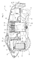
- Fig. 1
- is a side cross section view of a robotic mower according to a preferred embodiment of the invention.
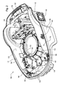
- Fig. 2
- is a top perspective view of the bottom chassis of a robotic mower according to a preferred embodiment of the invention.
- Fig. 3
- is an exploded perspective view of a robotic mower according to a preferred embodiment of the invention.
- Fig. 4
- is a side cross section view of a height of cut adjustment assembly according to a preferred embodiment of the invention.
- Fig. 5
- is a perspective view of a motor cup for a robotic mower height of cut adjustment assembly according to a preferred embodiment of the invention.
- Fig. 6
- is a cross section view of a portion of the bottom chassis and top cover of a robotic mower according to a preferred embodiment of the invention.
- In one embodiment shown in
Fig. 1 ,robotic mower 100 may be powered bybattery pack 122 that may be charged periodically using a charging station.Battery pack 122 may store electrical energy used to operate a pair of variable speedelectric motors 128 to turn a pair oftraction drive wheels 120, rotatecutting blade 138, and powervehicle control unit 139 that may be programmed to command electrictraction wheel motors 128 and operate functions of the robotic mower. Each traction wheel motor may be a DC brushed or DC brushless motor that controls one of the wheels. - In one embodiment shown in
Figs. 1 and3 ,top cover 102 may be removably attached and secured tobottom chassis 104.Control panel 105 may be removably attached to the top cover, and the control panel may be connected to the vehicle control unit for an operator to enter various commands using a keypad. A seal may be provided between the control panel and the top cover. Additionally, a stop button may be provided on the control panel. The stop button may be connected to the vehicle control unit to command the traction wheel motors and blade motor to stop. Preferably, the stop button may be connected to the vehicle control unit throughmagnet 109, without a wired connection extending outside of the top cover. - In one embodiment, bottom chassis may have a pair of walls, an
outer wall 106 and aninner wall 112, to define anouter cavity 116 and an inner cavity 117. The top cover may be attached to and cover the bottom chassis, and may form a seal with the outer wall and the inner wall to fully enclose each of the inner and outer cavities. Electronics and/or other critical components may be housed inside the inner cavity of the robotic mower. Inner cavity 117 has two barriers preventing moisture, dust, debris and other contaminants from reaching sensitive components and wired connections includingelectronic controller 139,battery pack 122, and one ormore boundary sensors 119. - In the embodiment shown in
Figs. 2 and3 ,outer cavity 116 may be provided betweenouter wall 106 andinner wall 112 of the robotic mower. Components that are less sensitive to moisture or dust may be housed inouter cavity 116. For example, the components inouter cavity 116 may includemounting clips 161 that may removably attach and lock the top cover onto the bottom chassis, andspindle mounting brackets 160 forcaster wheels 118. - In one embodiment,
outer wall 106 may have a groove orchannel 124 along its peripheral upper edge.Outer rim 108 of the top cover may engage and fit into groove orchannel 124 and may form an outer seal with the groove or channel. Additionally, flexibleelastomeric seal 110 may be positioned oninner wall 112 of the bottom chassis and may form a seal when it engages the top cover. The flexibleelastomeric seal 110 may be positioned on theupper edge 114 of the inner wall and seal withsurface 113 of the top cover to provide a water tight seal. Preferably, the lips of the flexible elastomeric seal may be compressed againstsurface 113 as the top cover is secured to the bottom chassis. - In one embodiment shown in
Fig. 6 , the top cover may be secured to the bottom chassis with a plurality of mounting clips orfasteners 161 extending between the bottom chassis and top cover, and may be tightened by threading or snap fit into nuts orretainers 164. Each mounting clip or fastener may extend through an opening in one of a plurality ofmounting platforms 163 in the bottom chassis, and may engage a nut or retainer captured in amounting platform 162 on the top cover. Each mounting clip may be accessible from the underside of the bottom chassis to attach, remove or tighten the top cover to the bottom chassis. - In one embodiment shown in
Figs. 1 ,3 and4 , height ofcut adjustment assembly 127 may be mounted to the bottom chassis so that it may extend through height of cutadjustment assembly hole 130. The height of cut adjustment assembly may include height ofcut drum 150 which may be secured to the bottom chassis withmounting flange 144. An O-ring seal may be positioned in groove orchannel 132 around the perimeter of the height of cut adjustment assembly hole to provide a seal between the mounting flange and the bottom chassis. Additionally,ring 146 may be provided between the mounting flange and height ofcut drum 150. - Still referring to
Figs. 1 ,3 and4 , in one embodiment,blade motor 134 may be mounted on the insidelower end surface 141 of height ofcut motor cup 142. The blade motor may be a direct driven electric motor connected toshaft 136 andcutting blade 138, and may be electrically connected to the controller byflexible cable 156 so that the blade motor may be raised and lowered as the height is adjusted. The cutting blade may include one or more horizontal cutting surfaces, and four cutting surfaces are shown in a preferred embodiment. The height of cut motor cup may be a generally cylindrical cup-shaped member, and the lower end of the height of cut motor cup may be mounted toblade shield 140. The height of cut motor cup may have a substantially greater height and diameter than the blade motor to provide sufficient air volume and circulation to avoid overheating the blade motor. - In one embodiment, an operator may manually raise and lower the blade shield and motor cup assembly to change the cutting height of the robotic mower. To change the height of cut, the operator may rotate the blade shield and motor cup to each desired cutting height.
Motor cup 142 may havespiral threads 148 around at least part of its external circumference, preferably near its openupper end 147. Thespiral threads 148 on the height of cut motor cup may engagespiral threads 143 on the height of cut drum so the motor cup and blade shield may move upwardly or downwardly by clockwise or counterclockwise rotation relative to the height of cut drum.Detents 149 may be provided along the spiral threads of the height of cut drum to hold and maintain the motor cup and blade shield at each height position selected by the operator. - As shown in
Fig. 5 , in one embodiment,detents 149 may enter and be captured ingaps 155 between each pair oframps spiral threads 148 on the outside of the motor cup. The gaps may be spaced at regular intervals around the spiral thread path of the motor cup. The detents may flex radially outwardly to slide up eachramp gap 155. The detent then may flex back radially inwardly to snap into and engage the gap. Additionally, each detent may have rounded edges so that it can slide into or disengage from each gap without hanging up, upon application of torque by the operator. - Now referring to
Figs. 4 and5 , in one embodiment,threads 143 anddetents 149 for the height of cut drum may be provided on a plurality of removable plastic blow molded inserts 152. The inserts may be positioned and fastened to the inside surface of the height of cut drum byclips 155. For example, sixinserts 152 may be provided in the height of cut drum, with each insert extending about 60 degrees around the inner circumference of the drum. Each of the six inserts may include its own thread start at its upper and lower ends, and the motor cup may have six thread starts so that it may engage all of the inserts at once. Additionally, the threads may have a pitch sufficiently great so that in one revolution, the motor cup and blade shield may move vertically at least about three inches, and preferably at least about four inches, between minimum and maximum cutting heights. For example, one revolution of the height of cut adjustment assembly may adjust between a minimum cutting height of less than about one inch, and a maximum cutting height of at least about four inches. Limiting the height of cut adjustment assembly to one revolution also reduces or prevents twisting or winding ofpower cable 156 to the motor. Having described the preferred embodiment, it will become apparent that various modifications can be made without departing from the scope of the invention as defined in the accompanying claims.
Claims (7)
- A robotic mower height of cut adjustment assembly, characterized by a height of cut drum (150) secured to a bottom chassis (104) of the robotic mower (100) and having internal spiral threads (148); a motor cup (142) supporting a cutting blade motor (134) and having external spiral threads (143) that engage the height of cut drum (150); a blade shield (140) fastened to the motor cup (1429; the blade shield (140) and the motor cup (142) may be rotated to change height of cut.
- The robotic mower height of cut adjustment assembly according to claim 1, characterized in that the blade shield (140) and motor cup (142) may be rotated one revolution to move the motor cup (142) and blade shield (140) vertically between a minimum and a maximum cutting height.
- The robotic mower height of cut adjustment assembly according to claim 1 or 2, characterized by a plurality of inserts (152) into the height of cut drum (150).
- The robotic mower height of cut adjustment assembly according to one of the previous claims, characterized in that the internal spiral threads (148) and the external spiral threads (148) each have a plurality of thread starts.
- The robotic mower height of cut adjustment assembly according to one of the previous claims, characterized by a plurality of detents (149) on the internal spiral threads (148) of the height of cut drum (150).
- The robotic mower height of cut adjustment assembly according to claim 5, characterized in that the detents (149) flex radially outwardly to slide up a plurality of ramped surfaces (151, 153) on the external threads (148) of the motor cup (142), and flex radially inwardly into gaps (155) between the ramped surfaces (151, 153).
- A robot mower (100) comprising a robot mower height of cut adjustment assembly according to one of the previous claims.
Applications Claiming Priority (1)
| Application Number | Priority Date | Filing Date | Title |
|---|---|---|---|
| US12/845,094 US8234848B2 (en) | 2010-07-28 | 2010-07-28 | Robotic mower height of cut adjustment assembly |
Publications (2)
| Publication Number | Publication Date |
|---|---|
| EP2412220A1 true EP2412220A1 (en) | 2012-02-01 |
| EP2412220B1 EP2412220B1 (en) | 2013-01-23 |
Family
ID=45316230
Family Applications (1)
| Application Number | Title | Priority Date | Filing Date |
|---|---|---|---|
| EP11173516A Not-in-force EP2412220B1 (en) | 2010-07-28 | 2011-07-12 | Robotic mower height of cut adjustment assembly and robotic mower |
Country Status (2)
| Country | Link |
|---|---|
| US (1) | US8234848B2 (en) |
| EP (1) | EP2412220B1 (en) |
Cited By (12)
| Publication number | Priority date | Publication date | Assignee | Title |
|---|---|---|---|---|
| EP2422602A1 (en) * | 2010-08-31 | 2012-02-29 | AL-KO Kober AG | Garden device |
| CN103999627A (en) * | 2014-04-30 | 2014-08-27 | 福州大学 | Mechanical structure device of intelligent mowing robot |
| EP2783563A1 (en) * | 2013-03-27 | 2014-10-01 | Viking GmbH | Work machine with an adjustable assembly |
| EP2869690A4 (en) * | 2012-07-04 | 2016-05-11 | Husqvarna Ab | CALIBRATION HEIGHT CALIBRATION FOR A ROBOTIC MOWER |
| EP3342268B1 (en) | 2017-01-02 | 2019-12-18 | LG Electronics Inc. | Lawn mower robot |
| CN110839394A (en) * | 2016-02-02 | 2020-02-28 | 美国iRobot公司 | Blade assembly for mowing mobile robot |
| CN111937567A (en) * | 2020-07-17 | 2020-11-17 | 广西科技大学 | A hybrid lawn mower |
| DE102020209524B4 (en) | 2019-08-09 | 2022-02-03 | Honda Motor Co., Ltd. | WORK MACHINE |
| EP3657929B1 (en) * | 2017-07-26 | 2022-03-09 | Kverneland Group Kerteminde AS | Electric powered disc mower |
| CN114287227A (en) * | 2020-10-08 | 2022-04-08 | 胡斯华纳有限公司 | Height adjustment device and robotic lawnmower comprising a height adjustment device |
| US11385059B2 (en) | 2017-05-26 | 2022-07-12 | Guangzhou Xaircraft Technology Co., Ltd | Method for determining heading of unmanned aerial vehicle and unmanned aerial vehicle |
| US11805728B2 (en) | 2019-08-09 | 2023-11-07 | Honda Motor Co., Ltd. | Work machine having vertically adjustable work unit |
Families Citing this family (65)
| Publication number | Priority date | Publication date | Assignee | Title |
|---|---|---|---|---|
| US8428776B2 (en) * | 2009-06-18 | 2013-04-23 | Michael Todd Letsky | Method for establishing a desired area of confinement for an autonomous robot and autonomous robot implementing a control system for executing the same |
| US8093831B2 (en) * | 2009-08-20 | 2012-01-10 | Qi Deng | Voltage converter with first push |
| EP2869691B1 (en) * | 2012-07-04 | 2017-08-23 | Husqvarna Ab | Secured screw-nut interface for a robotic mower |
| US9072218B2 (en) | 2012-07-09 | 2015-07-07 | Deere & Company | Boundary sensor assembly for a robotic lawn mower, robotic lawn mower and robotic lawn mower system |
| US9026299B2 (en) | 2012-07-09 | 2015-05-05 | Deere & Company | Navigation system and method for autonomous mower |
| EP2939508B1 (en) | 2012-12-28 | 2021-05-19 | Positec Power Tools (Suzhou) Co., Ltd | Automatic mowing system |
| US9699960B2 (en) * | 2013-08-14 | 2017-07-11 | Ariens Company | Mulching insert and system for mounting a mulching insert to a lawn mower |
| JP2017535279A (en) | 2014-09-23 | 2017-11-30 | 宝時得科技(中国)有限公司Positec Technology (China) Co.,Ltd. | Automatic mobile robot |
| JP6129231B2 (en) | 2015-03-27 | 2017-05-17 | 本田技研工業株式会社 | Lawn mower |
| JP6536681B2 (en) * | 2015-09-24 | 2019-07-03 | 工機ホールディングス株式会社 | Self-propelled mowing machine |
| CN106605488B (en) * | 2015-10-23 | 2019-10-22 | 科沃斯机器人股份有限公司 | Height adjustment mechanism and its automatic mower |
| JP6546289B2 (en) * | 2015-12-24 | 2019-07-17 | 本田技研工業株式会社 | Lawn mower |
| WO2017223568A1 (en) * | 2016-06-24 | 2017-12-28 | Mtd Products Inc | High-efficiency cutting system |
| US11172608B2 (en) | 2016-06-30 | 2021-11-16 | Tti (Macao Commercial Offshore) Limited | Autonomous lawn mower and a system for navigating thereof |
| US11172607B2 (en) * | 2016-06-30 | 2021-11-16 | Tti (Macao Commercial Offshore) Limited | Autonomous lawn mower and a system for navigating thereof |
| CN109416543B (en) | 2016-06-30 | 2022-11-08 | 创科(澳门离岸商业服务)有限公司 | Autonomous mower and navigation system thereof |
| US10405440B2 (en) | 2017-04-10 | 2019-09-03 | Romello Burdoucci | System and method for interactive protection of a mobile electronic device |
| KR101918995B1 (en) * | 2017-01-02 | 2018-11-16 | 엘지전자 주식회사 | Lawn mower robot |
| KR101918994B1 (en) * | 2017-01-02 | 2019-02-08 | 엘지전자 주식회사 | Lawn mower robot |
| KR101915547B1 (en) | 2017-01-02 | 2018-11-06 | 엘지전자 주식회사 | Lawn mower robot |
| CN206533741U (en) | 2017-02-15 | 2017-10-03 | 苏州宝时得电动工具有限公司 | A kind of hay mover |
| AU2019200410B2 (en) * | 2017-04-26 | 2021-01-28 | Tti (Macao Commercial Offshore) Limited | An autonomous lawn mower and a system for navigating thereof |
| US11470774B2 (en) | 2017-07-14 | 2022-10-18 | Irobot Corporation | Blade assembly for a grass cutting mobile robot |
| WO2019071061A1 (en) | 2017-10-06 | 2019-04-11 | Mtd Products Inc | High-efficiency lawn maintenance tool and high-efficiency cutting blade |
| EP3549425B1 (en) | 2018-04-06 | 2021-08-04 | LG Electronics Inc. | Lawn mower robot |
| EP3549427B1 (en) * | 2018-04-06 | 2021-09-01 | LG Electronics Inc. | Lawn mower robot |
| EP3549429B1 (en) * | 2018-04-06 | 2021-10-27 | LG Electronics Inc. | Lawn mower robot |
| EP3549424B1 (en) * | 2018-04-06 | 2022-01-05 | Lg Electronics Inc. | Lawn mower robot |
| EP3560312B1 (en) | 2018-04-06 | 2021-10-20 | LG Electronics Inc. | Lawn mower robot |
| EP3549423B1 (en) * | 2018-04-06 | 2021-06-16 | Lg Electronics Inc. | Lawn mower robot |
| EP3549426B1 (en) * | 2018-04-06 | 2021-09-08 | LG Electronics Inc. | Lawn mower robot |
| KR102231641B1 (en) * | 2018-04-06 | 2021-03-24 | 엘지전자 주식회사 | Lawn mower robot |
| US11166409B2 (en) * | 2018-04-06 | 2021-11-09 | Lg Electronics Inc. | Lawn mower robot |
| US10881047B2 (en) | 2018-06-04 | 2021-01-05 | Kubota Corporation | Robot mower with protruding blades |
| CN110622680B (en) * | 2018-06-21 | 2023-03-10 | 苏州宝时得电动工具有限公司 | Grass cutter |
| KR102072687B1 (en) * | 2018-09-12 | 2020-03-02 | 엘지전자 주식회사 | Lawn mower robot |
| KR102075465B1 (en) * | 2018-11-08 | 2020-02-10 | 엘지전자 주식회사 | Lawn mower robot |
| US11696526B2 (en) * | 2018-12-03 | 2023-07-11 | The Toro Company | Autonomous mower with adjustable cutting height |
| CN109618646B (en) * | 2019-02-22 | 2022-04-12 | 浙江白马实业有限公司 | A cutter head lifting structure and a lawn mower with the same |
| US11605961B2 (en) | 2019-09-13 | 2023-03-14 | Echo Incorporated | System for facilitating the charging of a battery-operated apparatus |
| KR102354130B1 (en) * | 2019-10-17 | 2022-01-21 | 엘지전자 주식회사 | Lawn mower robot |
| EP4054309B1 (en) * | 2019-11-04 | 2025-04-02 | The Toro Company | Autonomous mower |
| CN111466194B (en) * | 2019-11-22 | 2026-04-24 | 上海山科机器人有限公司 | Cutting mechanism and mower |
| DE102019220325A1 (en) * | 2019-12-20 | 2021-06-24 | Robert Bosch Gesellschaft mit beschränkter Haftung | mowing machine |
| EP3888440B1 (en) * | 2020-03-31 | 2025-01-29 | Globe (Jiangsu) Co., Ltd. | A robotic mower with integrated assemblies |
| CN111406500A (en) * | 2020-05-07 | 2020-07-14 | 常州格力博有限公司 | Lawn mower and electric tool |
| CN111972117A (en) * | 2020-09-09 | 2020-11-24 | 宁波奇亚园林工具有限公司 | Intelligent mower |
| SE2051268A1 (en) * | 2020-11-02 | 2022-05-03 | Husqvarna Ab | Lawnmower cutting assembly and lawnmower |
| SE545627C2 (en) * | 2020-11-13 | 2023-11-14 | Husqvarna Ab | Robotic work tool and method for running a robotic work tool |
| EP4014710B1 (en) * | 2020-12-17 | 2023-06-28 | Andreas Stihl AG & Co. KG | Autonomous mobile green area processing robot |
| US11812691B2 (en) | 2020-12-23 | 2023-11-14 | Robert Bosch Gmbh | Lawnmower |
| US12296694B2 (en) | 2021-03-10 | 2025-05-13 | Techtronic Cordless Gp | Lawnmowers |
| CN113207417B (en) * | 2021-05-25 | 2022-05-24 | 青岛市农业科学研究院 | Agricultural weeder with safeguard function |
| CN116097971B (en) * | 2021-11-09 | 2025-12-02 | 格力博(江苏)股份有限公司 | Lawn mower |
| US12443180B2 (en) | 2021-11-10 | 2025-10-14 | Techtronic Cordless Gp | Robotic lawn mowers |
| US20230180648A1 (en) * | 2021-12-15 | 2023-06-15 | Willand (Beijing) Technology Co., Ltd. | Mowing height adjusting device and automatic mower having same |
| AU2023200381A1 (en) | 2022-01-31 | 2023-08-17 | Techtronic Cordless Gp | Robotic garden tool |
| SE2250268A1 (en) * | 2022-02-28 | 2023-08-29 | Husqvarna Ab | Self-propelled Robotic Work Tool |
| EP4270138A1 (en) | 2022-04-28 | 2023-11-01 | Techtronic Cordless GP | Creation of a virtual boundary for a robotic garden tool |
| US20230380342A1 (en) * | 2022-05-25 | 2023-11-30 | Techtronic Cordless Gp | Robotic garden tool with blade height adjustment |
| US12472611B2 (en) | 2022-05-31 | 2025-11-18 | Techtronic Cordless Gp | Peg driver |
| AU2023204696A1 (en) | 2022-07-19 | 2024-02-08 | Techtronic Cordless Gp | Display for controlling robotic tool |
| EP4340296B1 (en) | 2022-07-29 | 2025-04-09 | Techtronic Cordless GP | Generation of a cryptography key for a robotic garden tool |
| US20250089607A1 (en) * | 2023-09-18 | 2025-03-20 | Black & Decker, Inc. | Height adjustment mechanism |
| USD1118706S1 (en) | 2025-01-07 | 2026-03-17 | Techtronic Cordless Gp | Lawnmower housing |
Citations (4)
| Publication number | Priority date | Publication date | Assignee | Title |
|---|---|---|---|---|
| GB1010481A (en) * | 1962-02-01 | 1965-11-17 | Webb H C & Co Ltd | Improvements relating to lawn mowers |
| DE2127247A1 (en) * | 1971-06-02 | 1972-12-14 | Hinz, Heinrich, 3300 Braunschweig | Reel mower |
| WO2003103375A1 (en) * | 2002-06-07 | 2003-12-18 | Aktiebolaget Electrolux | Self-propelled device with a sensor constituted of a hall effect transducer and an adjustable operational part |
| CN201491509U (en) * | 2009-09-04 | 2010-06-02 | 浙江亚特电器有限公司 | Mowing height adjustment structure of intelligent lawn mower |
Family Cites Families (9)
| Publication number | Priority date | Publication date | Assignee | Title |
|---|---|---|---|---|
| US2484201A (en) * | 1947-05-28 | 1949-10-11 | Laurence J Winchell | Lawn mower |
| US2796715A (en) * | 1954-10-20 | 1957-06-25 | Allover Mfg Co | Grass trimmer |
| US3114229A (en) * | 1962-05-25 | 1963-12-17 | Wilson Floyd Thomas | Rotary mower blade height adjuster |
| US4694639A (en) | 1985-12-30 | 1987-09-22 | Chen Sheng K | Robotic lawn mower |
| US4777785A (en) | 1986-02-04 | 1988-10-18 | Rafaels Raymond J | Method of guiding a robotic lawnmower |
| US7117660B1 (en) | 2000-04-12 | 2006-10-10 | Colens Andre | Self-propelled lawn mower |
| US7599758B2 (en) | 2003-09-19 | 2009-10-06 | Royal Appliance Mfg. Co. | Sensors and associated methods for controlling a vacuum cleaner |
| DE102004047790A1 (en) | 2004-10-01 | 2006-04-06 | Viking Gmbh | Mobile working device |
| US7707812B2 (en) * | 2008-01-22 | 2010-05-04 | Edward Kwok-Yen Cheung | Compact lawn mower |
-
2010
- 2010-07-28 US US12/845,094 patent/US8234848B2/en active Active
-
2011
- 2011-07-12 EP EP11173516A patent/EP2412220B1/en not_active Not-in-force
Patent Citations (4)
| Publication number | Priority date | Publication date | Assignee | Title |
|---|---|---|---|---|
| GB1010481A (en) * | 1962-02-01 | 1965-11-17 | Webb H C & Co Ltd | Improvements relating to lawn mowers |
| DE2127247A1 (en) * | 1971-06-02 | 1972-12-14 | Hinz, Heinrich, 3300 Braunschweig | Reel mower |
| WO2003103375A1 (en) * | 2002-06-07 | 2003-12-18 | Aktiebolaget Electrolux | Self-propelled device with a sensor constituted of a hall effect transducer and an adjustable operational part |
| CN201491509U (en) * | 2009-09-04 | 2010-06-02 | 浙江亚特电器有限公司 | Mowing height adjustment structure of intelligent lawn mower |
Cited By (20)
| Publication number | Priority date | Publication date | Assignee | Title |
|---|---|---|---|---|
| EP2422602A1 (en) * | 2010-08-31 | 2012-02-29 | AL-KO Kober AG | Garden device |
| EP3295781B1 (en) | 2012-07-04 | 2022-08-31 | Husqvarna AB | Robotic mower |
| EP2869690A4 (en) * | 2012-07-04 | 2016-05-11 | Husqvarna Ab | CALIBRATION HEIGHT CALIBRATION FOR A ROBOTIC MOWER |
| EP3295781A1 (en) * | 2012-07-04 | 2018-03-21 | Husqvarna AB | Robotic mower |
| EP2783563A1 (en) * | 2013-03-27 | 2014-10-01 | Viking GmbH | Work machine with an adjustable assembly |
| CN103999627B (en) * | 2014-04-30 | 2015-09-09 | 福州大学 | Mechanical structure device of intelligent lawn mowing robot |
| CN103999627A (en) * | 2014-04-30 | 2014-08-27 | 福州大学 | Mechanical structure device of intelligent mowing robot |
| CN110839394A (en) * | 2016-02-02 | 2020-02-28 | 美国iRobot公司 | Blade assembly for mowing mobile robot |
| CN110839394B (en) * | 2016-02-02 | 2021-06-01 | 美国iRobot公司 | Blade assembly for mowing mobile robot |
| EP3342268B1 (en) | 2017-01-02 | 2019-12-18 | LG Electronics Inc. | Lawn mower robot |
| US11385059B2 (en) | 2017-05-26 | 2022-07-12 | Guangzhou Xaircraft Technology Co., Ltd | Method for determining heading of unmanned aerial vehicle and unmanned aerial vehicle |
| EP3657929B1 (en) * | 2017-07-26 | 2022-03-09 | Kverneland Group Kerteminde AS | Electric powered disc mower |
| US11665997B2 (en) | 2017-07-26 | 2023-06-06 | Kverneland Group Kertem Inde As | Electric powered disc mower |
| DE102020209524B4 (en) | 2019-08-09 | 2022-02-03 | Honda Motor Co., Ltd. | WORK MACHINE |
| US11793110B2 (en) | 2019-08-09 | 2023-10-24 | Honda Motor Co., Ltd. | Work machine with height adjustable work unit |
| US11805728B2 (en) | 2019-08-09 | 2023-11-07 | Honda Motor Co., Ltd. | Work machine having vertically adjustable work unit |
| CN111937567A (en) * | 2020-07-17 | 2020-11-17 | 广西科技大学 | A hybrid lawn mower |
| CN114287227A (en) * | 2020-10-08 | 2022-04-08 | 胡斯华纳有限公司 | Height adjustment device and robotic lawnmower comprising a height adjustment device |
| EP3981240A1 (en) * | 2020-10-08 | 2022-04-13 | Husqvarna Ab | Height adjustment device and a robotic mower comprising a height adjustment device |
| US12232443B2 (en) | 2020-10-08 | 2025-02-25 | Husqvarna Ab | Height adjustment device and robotic mower comprising a height adjustment device |
Also Published As
| Publication number | Publication date |
|---|---|
| US20120023880A1 (en) | 2012-02-02 |
| EP2412220B1 (en) | 2013-01-23 |
| US8234848B2 (en) | 2012-08-07 |
Similar Documents
| Publication | Publication Date | Title |
|---|---|---|
| US8234848B2 (en) | Robotic mower height of cut adjustment assembly | |
| EP2412219B1 (en) | Robotic mower housing and robotic mower | |
| EP3909411B1 (en) | Mower with a sealed casing and a functional module for maintaining pressure balance or detecting a sealing state of the casing | |
| US20240416769A1 (en) | Robotic Mower | |
| EP3136835B1 (en) | Improved robotic work tool | |
| EP2625947B1 (en) | Lawn mower | |
| WO2016104187A1 (en) | Self-propelled lawn mower | |
| TWM461310U (en) | Lawn mower | |
| US20140067172A1 (en) | Electric Lawn Tractor Power Management System And Method | |
| CN115666221A (en) | Grass cutter | |
| EP4054309B1 (en) | Autonomous mower | |
| US12249875B2 (en) | Electric work machine | |
| WO2021203697A1 (en) | Lawn mower | |
| KR20170035030A (en) | Portable apparatus for ventilating gas of manhole | |
| CN116325411B (en) | A robotic lawnmower with integrated components | |
| US11808327B2 (en) | Linear actuator with an integrated variable frequency drive | |
| WO2014080037A2 (en) | The brush, the brush attaching system and a vacuum cleaner | |
| US20140082884A1 (en) | Brush, the brush attaching system and a vacuum cleaner | |
| CN215178623U (en) | Automobile engine attaches together detection instrument | |
| CN223979164U (en) | A mounting structure, a mowing module, and a garden robot | |
| CN121772993A (en) | Safety power tool |
Legal Events
| Date | Code | Title | Description |
|---|---|---|---|
| AK | Designated contracting states |
Kind code of ref document: A1 Designated state(s): AL AT BE BG CH CY CZ DE DK EE ES FI FR GB GR HR HU IE IS IT LI LT LU LV MC MK MT NL NO PL PT RO RS SE SI SK SM TR |
|
| AX | Request for extension of the european patent |
Extension state: BA ME |
|
| PUAI | Public reference made under article 153(3) epc to a published international application that has entered the european phase |
Free format text: ORIGINAL CODE: 0009012 |
|
| 17P | Request for examination filed |
Effective date: 20120801 |
|
| GRAP | Despatch of communication of intention to grant a patent |
Free format text: ORIGINAL CODE: EPIDOSNIGR1 |
|
| RIC1 | Information provided on ipc code assigned before grant |
Ipc: A01D 34/63 20060101ALI20120905BHEP Ipc: A01D 34/81 20060101ALI20120905BHEP Ipc: A01D 34/74 20060101ALI20120905BHEP Ipc: A01D 34/00 20060101AFI20120905BHEP |
|
| GRAS | Grant fee paid |
Free format text: ORIGINAL CODE: EPIDOSNIGR3 |
|
| GRAA | (expected) grant |
Free format text: ORIGINAL CODE: 0009210 |
|
| AK | Designated contracting states |
Kind code of ref document: B1 Designated state(s): AL AT BE BG CH CY CZ DE DK EE ES FI FR GB GR HR HU IE IS IT LI LT LU LV MC MK MT NL NO PL PT RO RS SE SI SK SM TR |
|
| REG | Reference to a national code |
Ref country code: GB Ref legal event code: FG4D |
|
| REG | Reference to a national code |
Ref country code: CH Ref legal event code: EP |
|
| REG | Reference to a national code |
Ref country code: AT Ref legal event code: REF Ref document number: 594461 Country of ref document: AT Kind code of ref document: T Effective date: 20130215 Ref country code: CH Ref legal event code: EP |
|
| REG | Reference to a national code |
Ref country code: IE Ref legal event code: FG4D |
|
| REG | Reference to a national code |
Ref country code: DE Ref legal event code: R096 Ref document number: 602011000838 Country of ref document: DE Effective date: 20130321 |
|
| REG | Reference to a national code |
Ref country code: AT Ref legal event code: MK05 Ref document number: 594461 Country of ref document: AT Kind code of ref document: T Effective date: 20130123 |
|
| REG | Reference to a national code |
Ref country code: LT Ref legal event code: MG4D |
|
| REG | Reference to a national code |
Ref country code: NL Ref legal event code: VDEP Effective date: 20130123 |
|
| PG25 | Lapsed in a contracting state [announced via postgrant information from national office to epo] |
Ref country code: BG Free format text: LAPSE BECAUSE OF FAILURE TO SUBMIT A TRANSLATION OF THE DESCRIPTION OR TO PAY THE FEE WITHIN THE PRESCRIBED TIME-LIMIT Effective date: 20130423 Ref country code: AT Free format text: LAPSE BECAUSE OF FAILURE TO SUBMIT A TRANSLATION OF THE DESCRIPTION OR TO PAY THE FEE WITHIN THE PRESCRIBED TIME-LIMIT Effective date: 20130123 Ref country code: NO Free format text: LAPSE BECAUSE OF FAILURE TO SUBMIT A TRANSLATION OF THE DESCRIPTION OR TO PAY THE FEE WITHIN THE PRESCRIBED TIME-LIMIT Effective date: 20130423 Ref country code: SE Free format text: LAPSE BECAUSE OF FAILURE TO SUBMIT A TRANSLATION OF THE DESCRIPTION OR TO PAY THE FEE WITHIN THE PRESCRIBED TIME-LIMIT Effective date: 20130123 Ref country code: BE Free format text: LAPSE BECAUSE OF FAILURE TO SUBMIT A TRANSLATION OF THE DESCRIPTION OR TO PAY THE FEE WITHIN THE PRESCRIBED TIME-LIMIT Effective date: 20130123 Ref country code: LT Free format text: LAPSE BECAUSE OF FAILURE TO SUBMIT A TRANSLATION OF THE DESCRIPTION OR TO PAY THE FEE WITHIN THE PRESCRIBED TIME-LIMIT Effective date: 20130123 Ref country code: IS Free format text: LAPSE BECAUSE OF FAILURE TO SUBMIT A TRANSLATION OF THE DESCRIPTION OR TO PAY THE FEE WITHIN THE PRESCRIBED TIME-LIMIT Effective date: 20130523 Ref country code: ES Free format text: LAPSE BECAUSE OF FAILURE TO SUBMIT A TRANSLATION OF THE DESCRIPTION OR TO PAY THE FEE WITHIN THE PRESCRIBED TIME-LIMIT Effective date: 20130504 |
|
| PG25 | Lapsed in a contracting state [announced via postgrant information from national office to epo] |
Ref country code: PT Free format text: LAPSE BECAUSE OF FAILURE TO SUBMIT A TRANSLATION OF THE DESCRIPTION OR TO PAY THE FEE WITHIN THE PRESCRIBED TIME-LIMIT Effective date: 20130523 Ref country code: GR Free format text: LAPSE BECAUSE OF FAILURE TO SUBMIT A TRANSLATION OF THE DESCRIPTION OR TO PAY THE FEE WITHIN THE PRESCRIBED TIME-LIMIT Effective date: 20130424 Ref country code: SI Free format text: LAPSE BECAUSE OF FAILURE TO SUBMIT A TRANSLATION OF THE DESCRIPTION OR TO PAY THE FEE WITHIN THE PRESCRIBED TIME-LIMIT Effective date: 20130123 Ref country code: LV Free format text: LAPSE BECAUSE OF FAILURE TO SUBMIT A TRANSLATION OF THE DESCRIPTION OR TO PAY THE FEE WITHIN THE PRESCRIBED TIME-LIMIT Effective date: 20130123 Ref country code: NL Free format text: LAPSE BECAUSE OF FAILURE TO SUBMIT A TRANSLATION OF THE DESCRIPTION OR TO PAY THE FEE WITHIN THE PRESCRIBED TIME-LIMIT Effective date: 20130123 Ref country code: PL Free format text: LAPSE BECAUSE OF FAILURE TO SUBMIT A TRANSLATION OF THE DESCRIPTION OR TO PAY THE FEE WITHIN THE PRESCRIBED TIME-LIMIT Effective date: 20130123 Ref country code: FI Free format text: LAPSE BECAUSE OF FAILURE TO SUBMIT A TRANSLATION OF THE DESCRIPTION OR TO PAY THE FEE WITHIN THE PRESCRIBED TIME-LIMIT Effective date: 20130123 |
|
| PG25 | Lapsed in a contracting state [announced via postgrant information from national office to epo] |
Ref country code: RS Free format text: LAPSE BECAUSE OF FAILURE TO SUBMIT A TRANSLATION OF THE DESCRIPTION OR TO PAY THE FEE WITHIN THE PRESCRIBED TIME-LIMIT Effective date: 20130123 Ref country code: HR Free format text: LAPSE BECAUSE OF FAILURE TO SUBMIT A TRANSLATION OF THE DESCRIPTION OR TO PAY THE FEE WITHIN THE PRESCRIBED TIME-LIMIT Effective date: 20130123 |
|
| PG25 | Lapsed in a contracting state [announced via postgrant information from national office to epo] |
Ref country code: SK Free format text: LAPSE BECAUSE OF FAILURE TO SUBMIT A TRANSLATION OF THE DESCRIPTION OR TO PAY THE FEE WITHIN THE PRESCRIBED TIME-LIMIT Effective date: 20130123 Ref country code: RO Free format text: LAPSE BECAUSE OF FAILURE TO SUBMIT A TRANSLATION OF THE DESCRIPTION OR TO PAY THE FEE WITHIN THE PRESCRIBED TIME-LIMIT Effective date: 20130123 Ref country code: EE Free format text: LAPSE BECAUSE OF FAILURE TO SUBMIT A TRANSLATION OF THE DESCRIPTION OR TO PAY THE FEE WITHIN THE PRESCRIBED TIME-LIMIT Effective date: 20130123 Ref country code: DK Free format text: LAPSE BECAUSE OF FAILURE TO SUBMIT A TRANSLATION OF THE DESCRIPTION OR TO PAY THE FEE WITHIN THE PRESCRIBED TIME-LIMIT Effective date: 20130123 Ref country code: CZ Free format text: LAPSE BECAUSE OF FAILURE TO SUBMIT A TRANSLATION OF THE DESCRIPTION OR TO PAY THE FEE WITHIN THE PRESCRIBED TIME-LIMIT Effective date: 20130123 |
|
| PG25 | Lapsed in a contracting state [announced via postgrant information from national office to epo] |
Ref country code: CY Free format text: LAPSE BECAUSE OF FAILURE TO SUBMIT A TRANSLATION OF THE DESCRIPTION OR TO PAY THE FEE WITHIN THE PRESCRIBED TIME-LIMIT Effective date: 20130123 |
|
| PLBE | No opposition filed within time limit |
Free format text: ORIGINAL CODE: 0009261 |
|
| STAA | Information on the status of an ep patent application or granted ep patent |
Free format text: STATUS: NO OPPOSITION FILED WITHIN TIME LIMIT |
|
| PG25 | Lapsed in a contracting state [announced via postgrant information from national office to epo] |
Ref country code: IT Free format text: LAPSE BECAUSE OF FAILURE TO SUBMIT A TRANSLATION OF THE DESCRIPTION OR TO PAY THE FEE WITHIN THE PRESCRIBED TIME-LIMIT Effective date: 20130123 |
|
| 26N | No opposition filed |
Effective date: 20131024 |
|
| REG | Reference to a national code |
Ref country code: DE Ref legal event code: R097 Ref document number: 602011000838 Country of ref document: DE Effective date: 20131024 |
|
| PG25 | Lapsed in a contracting state [announced via postgrant information from national office to epo] |
Ref country code: MC Free format text: LAPSE BECAUSE OF FAILURE TO SUBMIT A TRANSLATION OF THE DESCRIPTION OR TO PAY THE FEE WITHIN THE PRESCRIBED TIME-LIMIT Effective date: 20130123 |
|
| REG | Reference to a national code |
Ref country code: IE Ref legal event code: MM4A |
|
| REG | Reference to a national code |
Ref country code: FR Ref legal event code: ST Effective date: 20140331 |
|
| PG25 | Lapsed in a contracting state [announced via postgrant information from national office to epo] |
Ref country code: FR Free format text: LAPSE BECAUSE OF NON-PAYMENT OF DUE FEES Effective date: 20130731 |
|
| PG25 | Lapsed in a contracting state [announced via postgrant information from national office to epo] |
Ref country code: IE Free format text: LAPSE BECAUSE OF NON-PAYMENT OF DUE FEES Effective date: 20130712 |
|
| REG | Reference to a national code |
Ref country code: CH Ref legal event code: PL |
|
| PG25 | Lapsed in a contracting state [announced via postgrant information from national office to epo] |
Ref country code: LI Free format text: LAPSE BECAUSE OF NON-PAYMENT OF DUE FEES Effective date: 20140731 Ref country code: CH Free format text: LAPSE BECAUSE OF NON-PAYMENT OF DUE FEES Effective date: 20140731 |
|
| PG25 | Lapsed in a contracting state [announced via postgrant information from national office to epo] |
Ref country code: SM Free format text: LAPSE BECAUSE OF FAILURE TO SUBMIT A TRANSLATION OF THE DESCRIPTION OR TO PAY THE FEE WITHIN THE PRESCRIBED TIME-LIMIT Effective date: 20130123 |
|
| PG25 | Lapsed in a contracting state [announced via postgrant information from national office to epo] |
Ref country code: MT Free format text: LAPSE BECAUSE OF FAILURE TO SUBMIT A TRANSLATION OF THE DESCRIPTION OR TO PAY THE FEE WITHIN THE PRESCRIBED TIME-LIMIT Effective date: 20130123 Ref country code: TR Free format text: LAPSE BECAUSE OF FAILURE TO SUBMIT A TRANSLATION OF THE DESCRIPTION OR TO PAY THE FEE WITHIN THE PRESCRIBED TIME-LIMIT Effective date: 20130123 |
|
| PG25 | Lapsed in a contracting state [announced via postgrant information from national office to epo] |
Ref country code: HU Free format text: LAPSE BECAUSE OF FAILURE TO SUBMIT A TRANSLATION OF THE DESCRIPTION OR TO PAY THE FEE WITHIN THE PRESCRIBED TIME-LIMIT; INVALID AB INITIO Effective date: 20110712 Ref country code: MK Free format text: LAPSE BECAUSE OF FAILURE TO SUBMIT A TRANSLATION OF THE DESCRIPTION OR TO PAY THE FEE WITHIN THE PRESCRIBED TIME-LIMIT Effective date: 20130123 Ref country code: LU Free format text: LAPSE BECAUSE OF NON-PAYMENT OF DUE FEES Effective date: 20130712 |
|
| PG25 | Lapsed in a contracting state [announced via postgrant information from national office to epo] |
Ref country code: AL Free format text: LAPSE BECAUSE OF FAILURE TO SUBMIT A TRANSLATION OF THE DESCRIPTION OR TO PAY THE FEE WITHIN THE PRESCRIBED TIME-LIMIT Effective date: 20130123 |
|
| PGFP | Annual fee paid to national office [announced via postgrant information from national office to epo] |
Ref country code: DE Payment date: 20210621 Year of fee payment: 11 |
|
| REG | Reference to a national code |
Ref country code: DE Ref legal event code: R119 Ref document number: 602011000838 Country of ref document: DE |
|
| PG25 | Lapsed in a contracting state [announced via postgrant information from national office to epo] |
Ref country code: DE Free format text: LAPSE BECAUSE OF NON-PAYMENT OF DUE FEES Effective date: 20230201 |
|
| PGFP | Annual fee paid to national office [announced via postgrant information from national office to epo] |
Ref country code: GB Payment date: 20240729 Year of fee payment: 14 |
|
| GBPC | Gb: european patent ceased through non-payment of renewal fee |
Effective date: 20250712 |
|
| PG25 | Lapsed in a contracting state [announced via postgrant information from national office to epo] |
Ref country code: GB Free format text: LAPSE BECAUSE OF NON-PAYMENT OF DUE FEES Effective date: 20250712 |