EP2411802B1 - Verfahren und vorrichtung zur messung des massenanteils von wasser in öl-wasser-gemischen - Google Patents
Verfahren und vorrichtung zur messung des massenanteils von wasser in öl-wasser-gemischen Download PDFInfo
- Publication number
- EP2411802B1 EP2411802B1 EP10756450.2A EP10756450A EP2411802B1 EP 2411802 B1 EP2411802 B1 EP 2411802B1 EP 10756450 A EP10756450 A EP 10756450A EP 2411802 B1 EP2411802 B1 EP 2411802B1
- Authority
- EP
- European Patent Office
- Prior art keywords
- mixture
- temperature
- water
- sound velocity
- oil
- Prior art date
- Legal status (The legal status is an assumption and is not a legal conclusion. Google has not performed a legal analysis and makes no representation as to the accuracy of the status listed.)
- Not-in-force
Links
Images





Classifications
-
- G—PHYSICS
- G01—MEASURING; TESTING
- G01N—INVESTIGATING OR ANALYSING MATERIALS BY DETERMINING THEIR CHEMICAL OR PHYSICAL PROPERTIES
- G01N27/00—Investigating or analysing materials by the use of electric, electrochemical, or magnetic means
- G01N27/02—Investigating or analysing materials by the use of electric, electrochemical, or magnetic means by investigating impedance
- G01N27/04—Investigating or analysing materials by the use of electric, electrochemical, or magnetic means by investigating impedance by investigating resistance
- G01N27/14—Investigating or analysing materials by the use of electric, electrochemical, or magnetic means by investigating impedance by investigating resistance of an electrically-heated body in dependence upon change of temperature
- G01N27/18—Investigating or analysing materials by the use of electric, electrochemical, or magnetic means by investigating impedance by investigating resistance of an electrically-heated body in dependence upon change of temperature caused by changes in the thermal conductivity of a surrounding material to be tested
-
- G—PHYSICS
- G01—MEASURING; TESTING
- G01N—INVESTIGATING OR ANALYSING MATERIALS BY DETERMINING THEIR CHEMICAL OR PHYSICAL PROPERTIES
- G01N33/00—Investigating or analysing materials by specific methods not covered by groups G01N1/00 - G01N31/00
- G01N33/26—Oils; Viscous liquids; Paints; Inks
- G01N33/28—Oils, i.e. hydrocarbon liquids
- G01N33/2835—Specific substances contained in the oils or fuels
- G01N33/2847—Water in oils
-
- G—PHYSICS
- G01—MEASURING; TESTING
- G01F—MEASURING VOLUME, VOLUME FLOW, MASS FLOW OR LIQUID LEVEL; METERING BY VOLUME
- G01F1/00—Measuring the volume flow or mass flow of fluid or fluent solid material wherein the fluid passes through a meter in a continuous flow
- G01F1/66—Measuring the volume flow or mass flow of fluid or fluent solid material wherein the fluid passes through a meter in a continuous flow by measuring frequency, phase shift or propagation time of electromagnetic or other waves, e.g. using ultrasonic flowmeters
- G01F1/667—Arrangements of transducers for ultrasonic flowmeters; Circuits for operating ultrasonic flowmeters
- G01F1/668—Compensating or correcting for variations in velocity of sound
-
- G—PHYSICS
- G01—MEASURING; TESTING
- G01F—MEASURING VOLUME, VOLUME FLOW, MASS FLOW OR LIQUID LEVEL; METERING BY VOLUME
- G01F1/00—Measuring the volume flow or mass flow of fluid or fluent solid material wherein the fluid passes through a meter in a continuous flow
- G01F1/68—Measuring the volume flow or mass flow of fluid or fluent solid material wherein the fluid passes through a meter in a continuous flow by using thermal effects
- G01F1/684—Structural arrangements; Mounting of elements, e.g. in relation to fluid flow
- G01F1/688—Structural arrangements; Mounting of elements, e.g. in relation to fluid flow using a particular type of heating, cooling or sensing element
-
- G—PHYSICS
- G01—MEASURING; TESTING
- G01F—MEASURING VOLUME, VOLUME FLOW, MASS FLOW OR LIQUID LEVEL; METERING BY VOLUME
- G01F1/00—Measuring the volume flow or mass flow of fluid or fluent solid material wherein the fluid passes through a meter in a continuous flow
- G01F1/68—Measuring the volume flow or mass flow of fluid or fluent solid material wherein the fluid passes through a meter in a continuous flow by using thermal effects
- G01F1/684—Structural arrangements; Mounting of elements, e.g. in relation to fluid flow
- G01F1/688—Structural arrangements; Mounting of elements, e.g. in relation to fluid flow using a particular type of heating, cooling or sensing element
- G01F1/6882—Structural arrangements; Mounting of elements, e.g. in relation to fluid flow using a particular type of heating, cooling or sensing element making use of temperature dependence of acoustic properties, e.g. propagation speed of surface acoustic waves
Definitions
- the present invention is related to the measurement of the mass fractions of water and oil in a flowing mixture of oil and water through a pipe.
- references to the "present invention” or “invention” relate to exemplary embodiments and not necessarily to every embodiment encompassed by the appended claims.
- the present invention is related to the measurement of the mass fractions of water and oil in a flowing mixture where a temperature changer changes the temperature of the flowing oil water mixture by a measurable amount between a first time and a second time so the mass fraction can be determined from the change in the sound velocity in the mixture for a known change in temperature.
- US 4,059,987 discloses an apparatus and method for measuring the water content of oil flowing in a pipe.
- the apparatus and method employ sensors to measure the acoustical velocity of a sample of the fluid mixture prior to and after a temperature change.
- the water cut measurement of the present invention draws on the technology of technique 2 above, but overcomes its difficulties, as well as those of the other techniques, by a unique and hitherto unexploited approach.
- the present invention pertains to the measurement of the mass fraction of water in oil-water mixtures.
- the measurement is performed using ultrasonic transducers.
- the measurement is based on the fact that the mass fraction is related to the change in the sound velocity in the mixture for a known change in temperature.
- the apparatus 10 comprises a sensor portion 14 that measures sound velocity and temperature of the flowing oil water mixture at a first time and at a second time.
- the apparatus 10 comprises a temperature changer 16 in thermal communication with the flowing fluid which changes the temperature of the flowing oil water mixture by a measurable amount between the first time and the second time.
- the sensor portion 14 can include a first sensor portion 18 that measures the sound velocity and temperature of the flowing oil water mixture upstream of the temperature changer 16, and a second sensor portion 20 that measures the sound velocity and temperature of the flowing mixture downstream of the temperature changer 16.
- the temperature changer 16 can be either a heat exchanger that adds thermal energy to, or a cooler that removes thermal energy from the flowing mixture.
- the apparatus 10 can include a controller 22 and processor 24 that determine the mass fraction of the water and oil through an algorithm stored on a computer readable medium which is executed by the controller 22 and processor 24 that relates the mass fraction to the change in the sound velocity in the mixture for a known change in temperature.
- the oil water mixture can be emulsified so that droplets of a dispersed phase, which is either oil or water, are distributed throughout a continuous phase, which is either water or oil.
- the disbursal can be achieved by the flowing mixture moving at a velocity sufficient to achieve emulsification with essentially no slip.
- the apparatus 10 can include a pump 26 in fluid communication with the mixture to ensure the velocity of the sample mixture is made to meet or exceed the emulsification velocity requirement and wherein a portion of the flowing oil water mixture is continuously sampled and passed through the first and second sensor portions 18, 20 and the temperature changer 16 so as to allow determination of the change in mixture sound velocity for a measured change in temperature.
- the apparatus 10 can include a pump 26 in fluid communication with the mixture to ensure the velocity of the sample mixture is made to meet or exceed the emulsification velocity requirement and wherein several portions of the flowing oil water mixture are sampled, either continuously or successively.
- the samples can pass through the first and second sensor portions 18, 20 and the temperature changer 16 so as to allow the determination of the change in mixture sound velocity for a measured change in temperature for each sample location.
- the apparatus 10 can include a sampling arrangement 28 for sampling the fluid in communication with the first sensor portion 18.
- the sampling arrangement 28 can include a plurality of taps 30 disposed at different radii in the pipe 12 which sample the mixture.
- the sampling arrangement 28 can include valves 32 for each tap that are maintained open for a period long enough to ensure a representative sound velocity and temperature measurement for the associated tap location.
- the first sensor portion 18 can include a sound velocity transducer 34 and a reflecting plug 36.
- the sound velocity C of the mixture can be determined from the transit time t of a pulse of ultrasound from the transducer that travels to the reflecting plug 36 of the sensor and back to the transducer.
- the present invention pertains to a method for measuring a water mass fraction in a flowing mixture of oil and water through a pipe 12.
- the method comprises the steps of measuring sound velocity and temperature of the flowing oil water mixture at a first time with a sensor portion 14. There is the step of changing the temperature of the flowing oil water mixture by a measurable amount with a temperature changer 16 in thermal communication with the flowing fluid. There is the step of measuring sound velocity and temperature of the flowing oil water mixture at a second time with the sensor portion 14.
- the measuring step at a first time can include the step of measuring the sound velocity and temperature of the flowing oil water mixture with a first sensor portion 18 of the sensor portion 14 upstream of the temperature changer 16, and the measuring step at a second time includes the step of measuring the sound velocity and temperature of the flowing oil water mixture with a second sensor portion 20 of the sensor portion 14 downstream of the temperature changer 16.
- the temperature changer 16 can be either a heat exchanger that adds thermal energy to, or a cooler that removes thermal energy from the flowing mixture.
- a dispersed phase which is either oil or water
- the sampling step can include the step of sampling the mixture with a plurality of taps 30 disposed at different radii in the pipe 12 of the sampling arrangement 28.
- sound velocity-the propagation velocity of a pressure wave through a physical medium- is a function of the ratio of the stiffness and the density of the medium.
- the phases For a sound velocity measurement to characterize the components of an oil-water mixture, the phases must be dispersed, so that the stiffness and density of each component of the mixture participate in the pressure wave propagation. Furthermore, the length of the pressure wave must be long compared to the dimensions of the dispersed phase, to prevent the multiple phase interfaces in the wave path from excessively scattering the acoustic energy.
- Equation (1) below for the sound velocity of an oil-water mixture as a function of the ratio K, the mass of water in the mixture, M1, to the mass of oil in the mixture, M2: 1 / C 2 K + 1 / K / SG 1 + 1 / SG 2 2 ⁇ K / SG 1 ⁇ C 1 2 + 1 / SG 2 ⁇ C 2 2
- C is the velocity, in the mixture, of sound (or ultrasound-the frequency does not affect the velocity).
- K is defined as the ratio of the mass of water M1 to the mass of oil M2. [K is more precisely defined as the ratio of the mass flow rate of water W 1 to the mass flow rate of oil W 2. ] From this definition, the mass fraction of water with respect to the total mass is K/(K + 1).
- SG 1 is the specific gravity of the water in the mixture under the conditions of the measurement/
- SG 2 is the specific gravity of the oil in the mixture under the conditions of the measurement.
- C 1 is the velocity of sound in the water in the mixture for the conditions of the measurement (i.e., the temperature, and, weakly, the pressure of the mixture and the salinity of the water).
- C 2 is the velocity of sound in the oil in the mixture for the conditions of the measurement.
- this variable depends on the molecular specifics of the crude, its temperature, and, again weakly, its pressure.
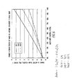
- Figure 1 plots the sound velocity measured for a mixture of water and oil, each having known properties, against the mass fraction of water in the mixture, for a limited range of water mass fractions (0 to 10%).
- water cut is the volume fraction of water. The relationship between the two terms is straightforward, if the specific gravities of the constituents are known.
- the volume fraction of water in the mixture V 1 /(V 1 +V 2 ) is given by M 1 v 1 /(M 1 v 1 + M 2 v 2 ) where v 1 and v 2 are the specific volumes of the water and oil respectively.
- Figure 1 also plots the mixture sound velocity calculated using equation (1) against the water mass fraction.
- the calculated mixture sound velocity (the "mass weighted” velocity of the figure) is lower than the measured velocity by about 0.1%.
- a volume weighted calculated velocity is about 0.07% higher than the measured sound velocity.
- the volume weighted figure is of doubtful physical significance.
- the source of the discrepancy between sound velocity predicted by equation (1) and the measured sound velocity may be due to the configuration of the experiment (as noted in the reference) but may also be due to slip-the velocity of the dispersed phase, water in this case, is not necessarily the same as that of the continuous phase. Equation (1) takes no account of slip. Furthermore, slip can vary with the specifics of the measurement.
- equation (1) A re-examination of equation (1) reveals several drawbacks to the use of mixture sound velocity alone to measure water cut. More specifically, the sound velocities of the constituent phases must be known precisely, for the conditions of the measurement, specifically the temperature of both phases and the salinity of the water phase. This becomes evident from the scale of Figure 1 -an oil temperature change of 1.7°C (3°F) can change 1.7°C the mixture sound velocity by 6.4m/second (250 in/sec), which corresponds to a 10% change in water cut. Thus if one is to make a determination of water cut to within, say, ⁇ 1%, he must measure temperature to better than ⁇ 1.7°C (0.3 °F), on an absolute basis.
- the means for measurement of water cut proposed herein exploits the responses of the constituents of a water-oil mixture to a change in temperature.
- the response of the sound velocity of water to an increase in temperature is very different from the response of the sound velocity of oil.
- the difference is evident from the data of Figures 2 , 3 , 4 and 5 .
- the data of the figures describe the behavior of sound velocity with temperature for the temperature range in which most water cut measurements are made: 2.3 to 60°C(40 °F to 140 °F).
- Figure 2 plots the sound velocity of water against temperature;
- Figure 3 plots the incremental change in sound velocity of water per degree C(Fahrenheit)
- Figure 4 plots the sound velocity of four typical crudes covering a range of specific gravities, again against temperature.
- Figure 5 is a bar chart showing the incremental change in sound velocity per degree C (Fahrenheit) for 55 different crudes, in the temperature range of interest.
- Figures 6 , 7, and 8 show the sound velocity changes for a 0.56 °C(1 °F) increase in mixture temperature over water mass fractions ranging from zero to 100%.
- Figure 6 represents the response of a typical heavy crude
- Figure 7 a medium crude
- Figure 8 a light crude.
- Each figure shows the sound velocity response for three different mixture temperatures covering the full range of potential applications 4 °C, 38°C, and 60°C (40 °F, 100 °F, and 140 °F).
- a comparison of the figures shows the strengths of a measurement using the proposed means for a mixture temperature change of only 0.56°C (1 °F):
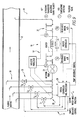
- Figures 9 and 10 illustrate one implementation of the present technique for water cut measurement.
- Figure 9 shows an oil water mixture flowing in a pipe 12.
- the diameter of the pipe 12 is selected so as to maintain the mixture velocity above 3m/second (10 feet per second), to ensure emulsification and minimal slip.
- the sample arrangement (4 taps 30 located at different radii within the pipe 12) enhances the precision of the measurement. Locating the taps 30 according to the rules of numerical integration (e.g., Gaussian quadrature) and weighting the mass fractions at each location as prescribed by the integration method allows the calculation of bulk average water cut with lower uncertainty.
- Gaussian quadrature e.g., Gaussian quadrature
- the sample tap arrangement allows sampling to proceed from each tap in turn, through the operation of the solenoid valves S1 through S4. Each valve is maintained open for a period long enough to ensure representative sound velocity and temperature measurements for the associated tap location.
- the metering pump 26 ensures that the velocity of the mixture in the sample piping is maintained above that necessary to minimize slip and maintain emulsification.
- Figure 10 shows one arrangement of sensors for the measurement of sound velocity and temperature.
- the diameter of the sensor piping is chosen to ensure that, given the flow rate of the sample pump 26, the mixture remains emulsified.
- a sensor of the requisite accuracy-an RTD or thermocouple measures the temperature of the incoming sample mixture.
- the sensor is located at the 90° inlet bend to ensure a measurement representative of the sample liquid.
- the sample is then directed through a second 90° bend in which is located a piezoceramic sound velocity transducer 34.
- the diameter and frequency of the ultrasonic transducer and the configuration of the sensor tube are chosen to ensure that, given the diameter of the sensor assembly in the way of the transit time measurement, the walls of the sensor assembly due not interfere with the transit of the pulse.
- this section of the sensor assembly is horizontal, to avoid gravitationally induced slip in the sample mixture.
- the effect of fluid velocity on the sound velocity measurement is intrinsically nullified by the pulse echo arrangement.
- the pulse transit time measurements will include the travel times of the pulse through non fluid media-the delays of the cable, electronics, and the acoustic "window" of the transducer assembly. These delays can be calculated (or measured offline). In any event, a highly accurate determination of the delay in non fluid media is not required because the method relies entirely on the difference in sound velocities of the mixture at two different temperatures. Means for dealing with the difference in the delays of the two measurements in a manner consistent with the accuracy goals of the measurement are discussed further in Appendix A.
- the electric heater downstream of the inlet sensor assembly in Figure 9 raises the temperature of the mixture by a preset amount.
- the digitally based transit time measurement allows the determination of the difference in sound velocities, hot vs. cold, to within a few parts in 100,000, a temperature increase of as little as 1°C (2 °F) is sufficient to produce an accurate measurement of the change in mixture sound velocity.
- the proposed means can work just as effectively if the temperature of the sample is cooled by 1°C (2 °F).
- the heater-cooler choice would be based on the temperature of the incoming oil-water mixture and the amount of power required to affect the heating versus the cooling.
- the sample mixture Downstream of the heater (or cooler), the sample mixture is directed thorough the second sound velocity and temperature sensor assembly. After passing through this sensor assembly, the mixture is returned to the pipe 12 from which it was extracted.
- the data processing of the proposed system should account for the transport delay through the piping and the heater (or cooler) between the sensors which measure sound velocity and temperature at the upstream and downstream locations.
- the data processing must take the difference between the measurements at the hot (or cold) sensor and the measurements at the inlet sensor taken earlier by an amount equal to the transport delay. This measure is necessary because the water cut may vary in time; failure to account for the transport delay will introduce “noise” and possibly biases into the water cut measurement.
- Heater power and flow rate affect the performance of the sample system illustrated in Figure 9 .
- the system cost is minimized if power and flow rate requirements are low.
- accuracy is enhanced with increased temperature rise (or fall).
- larger ultrasonic transducers can be accommodated in larger sensor pipe 12 diameters, which require higher flow. Larger transducers maximize the strength of the received ultrasonic signals while still avoiding interaction of the acoustic wave with the pipe 12 wall. Design tradeoffs are illustrated in the table below.
- Appendix A defines the algorithms and analyzes the uncertainties in the measurement System 3 of the table above. It concludes that uncertainties in the measurement of water cut with this system are about ⁇ 1 ⁇ 2 % water cut at water cuts near 0% and 100%. The uncertainties increase to about ⁇ 2/3 % water cut in the mid range of water cuts (20% to 70%). Increasing the heating (or cooling) so as to double the temperature increase (or decrease) in system 3 would halve these uncertainties.
- FIG. 9 Design tradeoffs for systems to measure the water cut of a sample of a flowing water-oil mixture are given in a table herein.
- Figures 9 and 10 depict the arrangement of the sample measurement systems.
- a 5 kW heater provides a temperature rise of 1°C (2 °F) for a sample flow rate of 0.068 m 3 /min (17 gpm).
- This flow rate in a 2.1 mm (0.83 inch) diameter pipe 12 produces a fluid velocity of 3 m/s (10 feet/sec), which is assumed sufficient to ensure an emulsified sample with little slip.
- This system will be used as a reference to establish the accuracy of the measurements of the change in sound velocity and the change in temperature, as well as the accuracy of other fluid properties used to calculate the accuracy of the water cut determination over the full water cut range.
- An input mixture temperature in the 38°C (100 °F) range was chosen for the analysis.
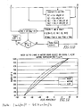
- the mixture sound velocity change per unit temperature change, dC/dT varies from -3.7 m/s/°C (- 81 inches per second per °F) at 0 % water, to 1.6 m/s/°C(+ 36 inches per second per °F) at 100% water cut.
- Figure 12 produced from the analyses supporting the present invention, shows that, for a heavy crude, intermediate values of water cut are related to dC/dT by what is essentially a straight line connecting these end points.
- the medium and lighter crudes in this example share the same end points, but depart from linearity because of the differences in the properties of the constituents, 53mm/s/°C specifically sound velocity and density (which is strongly correlated with sound velocity).
- a sensitivity analysis performed in support of the present invention demonstrated that, with an approximate knowledge of the constituent properties, a correction could be applied to the linear relationship to achieve good water cut accuracy (a quantitative analysis of this correction is given later in this analysis).
- the overall accuracy of the water cut determination rests on the accuracy of the dC/dT measurement: for this example, 53mm/s/°C (1.17 inches per second per degree F) per % water cut.
- the 1°C (two degree F) change in the temperature of the sample of the reference system this amounts to a 60mm/s (2.34 inch/sec)change in sound velocity for a 1% change in water cut.
- the issues are: (1) Can a change in mixture sound velocity of 60 mm/s (2.34 inches per second) be measured with sufficient accuracy to support a ⁇ 1% water cut measurement? and (2) Can a change in mixture temperature of 1°C (2 °F) be measured with sufficient accuracy to support a ⁇ 1% water cut measurement?
- the sound velocity of crude oil-water mixtures is in the order of 1397 m/s (55,000 inches per second), so that the requirement to detect and measure a change of 60 mm/s (2.34 inches/second) amounts to a precision requirement of about 1 part in 24,000.
- the time that is measured will include not only the transit time in the fluid but the delays in the transmission of energy from a transmitter through cables, transducers, acoustic windows and signal detection electronics.
- the sound velocities as measured by the sensors upstream (C) and downstream (H) of the heater element are, respectively:
- C C 2 L / t C - ⁇
- ⁇ t is the difference in transit time produced by heating the fluid in the heater.
- ⁇ C 2 L ⁇ t C - ⁇ - t C + ⁇ t - ⁇ / t C + ⁇ t - ⁇ ⁇ t C - ⁇
- Equation (A-4A) The approximation of equation (A-4A) is justified as follows: For the sensors of the reference system, a path length L of 127 mm (5 inches) has been selected. With this path length, a 12.7 mm (1 ⁇ 2 inch) diameter, 3 MHz transducer produces a focused beam that does not interact with the 21 mm(0.83 inch) diameter tubular walls of the sensor. The net transit time in the fluid (t C - ⁇ ) for a packet of 3 MHz acoustic energy with these parameters is nominally 167 ⁇ seconds at the inlet temperature of 38°C (100 °F).
- the change in sound velocity produced by 1°C (2 °F) of heating causes a change in transit time, ⁇ t, of 6.5 nanoseconds for a change in water cut of 1%. Relative to t C the ⁇ t can therefore be neglected in the denominator product.
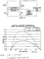
- FIG. 13 shows a sample schematic of a system for this purpose, using precision RTDs for both the hot leg and cold leg temperature measurements.
- Each RTD has a resistance of 100 ⁇ at 0°C (32 °F) with a sensitivity of approximately 0.4 ⁇ /°C (0.214 ⁇ /°F).
- the correction to a linear relationship between water cut and dC/dT can be calculated iteratively using the water cut determined using the linear (heavy oil) water cut vs. dC/dT curve and calculating the hot and cold mixture sound velocities, C(T H ) and C(T C ) respectively, using the mixture sound velocity equation (1).
- the operative equations are reproduced below.
- the properties subscripted 1 are those of the water in the mixture; the variables subscripted 2 are those of the oil.
- K is the ratio of water mass flow rate to oil mass flow rate. On a mass basis, water cut equals K/(K + 1).
- the difference in the calculated mixture sound velocities is then compared with the measured difference. If they are not the same within a selected tolerance ( ⁇ 0.1%), the water cut is adjusted until they are.
- Figure 14 has been constructed using this methodology. Analysis of Figure 14 indicates that for a given measurement of dC/dT, the correction from a linear relationship between water cut and dC/dT is linearly proportional to the difference between the water sound velocity for the conditions of the measurement C 1 (T C ) and the oil sound velocity, C 2 (T C )-that is, [C 1 (T C ) - C 2 (T C )].
- the variables C 1 (T C ) and C 2 (T C ) are determined with the measured mixture temperature T C as an entry variable to look-up tables, which characterize the sound velocities of the water and the crude as a function of their temperature.
- the tables are constructed from published data for saline water and crude oils. Inputs by the user for water salinity and for the crude oil source focus the look-up.
- T C The temperature used to establish the constituent sound velocities, T C is determined from the voltage measured across the cold (heater inlet) RTD in the resistance bridge of Figure 13 .
- an accuracy of between ⁇ 0.5 and ⁇ 1°C ( ⁇ 1 an ⁇ 2 °F) can be achieved with the arrangement of the figure.
- This performance is achieved by ensuring low self heating of the RTDs (which the low current of the bridge circuit of Figure 13 ensures) and low resistance RTD connections.
- Thermal insulation of the exterior of the sensor assembly from its surroundings is also desired, to reduce the effect of ambient temperature on the measurement. Heat transfer between the mixture and the RTD is inhibited by the low conductivity of the oil; hence the temperature measurement is vulnerable to variations in exterior temperature, where wind and rainwater may facilitate heat transfer between the air and the exterior of the RTD assembly.
- the ⁇ 0.44% uncertainty due to constituent properties is a maximum; as can be seen in Figure 14 the corrections to a linear water cut vs. dC/dT relationship approach the 14.9% used in the table above only in the mid range of water cuts. In this range the total measurement uncertainty of the reference system is the root sum squares of the slope uncertainty, ⁇ 0.51% and the constituent uncertainty ⁇ 0.44% or ⁇ 0.67%. Thus, over the range of water cuts from 0% to 100% the uncertainty of the water cut measurement of the reference system lies between ⁇ 0.51 % and 0.67% water cut depending on the water cut itself.
Landscapes
- Chemical & Material Sciences (AREA)
- Physics & Mathematics (AREA)
- Life Sciences & Earth Sciences (AREA)
- General Physics & Mathematics (AREA)
- Health & Medical Sciences (AREA)
- Engineering & Computer Science (AREA)
- Chemical Kinetics & Catalysis (AREA)
- Pathology (AREA)
- Immunology (AREA)
- General Health & Medical Sciences (AREA)
- Biochemistry (AREA)
- Analytical Chemistry (AREA)
- Medicinal Chemistry (AREA)
- Food Science & Technology (AREA)
- Fluid Mechanics (AREA)
- Oil, Petroleum & Natural Gas (AREA)
- General Chemical & Material Sciences (AREA)
- Electrochemistry (AREA)
- Electromagnetism (AREA)
- Investigating Or Analyzing Materials By The Use Of Ultrasonic Waves (AREA)
Claims (13)
- Vorrichtung (10) zum Messen der Mengenanteile von Wasser und Öl in einem fließenden Öl- und Wassergemisch durch ein Rohr (12), wobei die Vorrichtung Folgendes umfasst:einen Sensorteil (14), der Schallgeschwindigkeit und Temperatur des fließenden Öl-Wasser-Gemischs zu einem ersten Zeitpunkt und einem zweiten Zeitpunkt misst; undeinen Temperaturtauscher (16) in thermischer Verbindung mit dem fließenden Fluid, der die Temperatur des fließenden Öl-Wasser-Gemischs zwischen dem ersten Zeitpunkt und dem zweiten Zeitpunkt ändert;dadurch gekennzeichnet, dass:der Sensorteil (14) einen ersten Sensorteils (18), der Schallgeschwindigkeit und Temperatur des fließenden Öl-Wasser-Gemischs stromaufwärts von dem Temperaturtauscher (16) misst, und einen zweiten Sensorteil (20) aufweist, der Schallgeschwindigkeit und Temperatur des fließenden Gemischs stromabwärts vom Temperaturtauscher (16) misst.
- Vorrichtung (10) nach Anspruch 1, dadurch gekennzeichnet, dass der Temperaturtauscher (16) entweder ein Wärmetauscher, der dem fließenden Gemisch Wärmeenergie hinzufügt, oder ein Kühler ist, der Wärmeenergie davon abzieht.
- Vorrichtung (10) nach einem vorherigen Anspruch, dadurch gekennzeichnet, dass sie ferner eine Steuerung (22) und einen Prozessor (24) umfasst, der den Mengenanteil des Wassers und Öls durch einen auf einem computerlesbaren Medium gespeicherten Algorithmus ermittelt, der von der Steuerung (22) und dem Prozessor (24) ausgeführt wird, der den Mengenanteil auf die Änderung der Schallgeschwindigkeit in dem Gemisch für eine bekannte Temperaturänderung bezieht.
- Vorrichtung (10) nach einem vorherigen Anspruch, dadurch gekennzeichnet, dass das Öl-Wasser-Gemisch emulgiert wird, so dass Tröpfchen einer dispergierten Phase, die entweder Öl oder Wasser ist, über eine kontinuierliche Phase verteilt werden, die entweder Wasser oder Öl ist, wobei die genannte Dispersion erzielt wird, indem das fließende Gemisch sich mit einer Geschwindigkeit bewegt, die zum Erzielen einer Emulgierung im Wesentlichen ohne Schlupf ausreicht.
- Vorrichtung (10) nach Anspruch 4, dadurch gekennzeichnet, dass sie ferner eine Pumpe (26) in Fluidverbindung mit dem Gemisch umfasst, um zu gewährleisten, dass die Geschwindigkeit des Probengemischs die Emulgierungsgeschwindigkeitsanforderung erfüllt oder übertrifft, und wobei fortlaufend Proben von einem Teil des fließenden Öl-Wasser-Gemischs genommen und durch den ersten und zweiten Sensorteil (18, 20) und den Temperaturtauscher (16) geleitet werden, so dass die Änderung der Gemischschallgeschwindigkeit für eine gemessene Temperaturänderung ermittelt werden kann; oder wobei mehrere Proben von Teilen des fließenden Öl-Wasser-Gemischs, entweder kontinuierlich oder sukzessiv, genommen werden, wobei die genannten Proben, entweder einzeln oder in Kombination, durch den ersten und zweiten Sensorteil (18, 20) und den Temperaturtauscher (16) fließen, so dass die Änderung der Gemischschallgeschwindigkeit für eine gemessene Temperaturänderung für jeden Probenort ermittelt werden kann.
- Vorrichtung (10) nach einem vorherigen Anspruch, dadurch gekennzeichnet, dass sie ferner eine Probenahmeanordnung (28) zum Nehmen von Proben des Fluids in Verbindung mit dem ersten Sensorteil (18) umfasst.
- Vorrichtung (10) nach Anspruch 6, dadurch gekennzeichnet, dass die Probenahmeanordnung (28) mehrere Abgriffe (30) umfasst, die in unterschiedlichen Radien in dem Rohr (12) angeordnet sind, in dem Proben des Gemischs genommen werden; wobei vorzugsweise die Probenahmeanordnung (28) Ventile (32) für jeden Abgriff aufweist, die für eine Periode offen gehalten werden, die ausreicht, um eine repräsentative Schallgeschwindigkeits- und Temperaturmessung für den assoziierten Abgriffort zu gewährleisten.
- Vorrichtung (10) nach einem vorherigen Anspruch, dadurch gekennzeichnet, dass der erste Sensorteil (18) einen Schallgeschwindigkeitswandler (34) und einen reflektierenden Stopfen (36) aufweist, wobei die Schallgeschwindigkeit C des Gemischs anhand der Transitzeit t eines Ultraschallimpulses vom Wandler, der zu dem reflektierenden Stopfen (36) des Sensors und zurück zum Wandler wandert, ermittelt wird.
- Verfahren zum Messen von Wassermengenanteilen in einem fließenden Gemisch von Öl und Wasser durch ein Rohr (12), das die folgenden Schritte beinhaltet:Messen von Schallgeschwindigkeit und Temperatur des fließenden Öl-Wasser-Gemischs zu einem ersten Zeitpunkt mit einem Sensorteil (14);Ändern der Temperatur des fließenden Öl-Wasser-Gemischs um einen messbaren Betrag mit einem Temperaturtauscher (16) in thermischer Verbindung mit dem fließenden Fluid; undMessen von Schallgeschwindigkeit und Temperatur des fließenden Öl-Wasser-Gemischs zu einem zweiten Zeitpunkt mit dem Sensorteil (14); undErmitteln des Wassermengenanteils;dadurch gekennzeichnet, dassder Messschritt zu einem ersten Zeitpunkt den Schritt des Messens von Schallgeschwindigkeit und Temperatur des fließenden Öl-Wasser-Gemischs mit einem ersten Sensorteil (18) des Sensorteils (14) stromaufwärts vom Temperaturtauscher (16) beinhaltet, und der Messschritt zu einem zweiten Zeitpunkt den Schritt des Messens von Schallgeschwindigkeit und Temperatur des fließenden Öl-Wasser-Gemischs mit einem zweiten Sensorteil (20) des Sensorteils (14) stromabwärts von dem Temperaturtauscher (16) beinhaltet.
- Verfahren nach Anspruch 9, dadurch gekennzeichnet, dass der Temperaturtauscher (16) entweder ein Wärmetauscher, der dem fließenden Gemisch Wärmeenergie hinzufügt, oder ein Kühler ist, der Wärmeenergie davon abzieht.
- Verfahren nach Anspruch 9 oder 10, gekennzeichnet durch den Schritt des Ermittelns des Mengenanteils des Wassers mit einem auf einem computerlesbaren Medium gespeicherten Algorithmus, der von einer Steuerung (22) und einem Prozessor (24) ausgeführt wird, der den Mengenanteil auf die Änderung der Schallgeschwindigkeit in dem Gemisch für eine bekannte Temperaturänderung bezieht.
- Verfahren nach einem der Ansprüche 9 bis 11, gekennzeichnet durch den Schritt des Emulgierens des Öl-Wasser-Gemischs, so dass Tröpfchen einer dispergierten Phase, die entweder Öl oder Wasser ist, über eine kontinuierliche Phase verteilt werden, die entweder Wasser oder Öl ist, wobei die genannte Dispersion erzielt wird, indem sich das fließende Gemisch mit einer Geschwindigkeit bewegt, die zum Erzielen von Emulgierung im Wesentlichen ohne Schlupf ausreicht.
- Verfahren nach Anspruch 12, gekennzeichnet durch den Schritt des Pumpens des Gemischs mit einer Pumpe (26) in Fluidverbindung mit dem Gemisch, um zu gewährleisten, dass die Geschwindigkeit des Probengemischs die Emulgierungsgeschwindigkeitsanforderung erfüllt oder übertrifft, und wobei fortlaufend Proben von einem Teil des fließenden Öl-Wasser-Gemischs genommen und durch den ersten und zweiten Sensorteil (18, 20) und den Temperaturtauscher (16) geleitet werden, so dass die Änderung der Schallgeschwindigkeit des Gemischs für eine gemessene Temperaturänderung ermittelt werden kann; oder durch den Schritt des Pumpens des Gemischs mit einer Pumpe (26) in Fluidverbindung mit dem Gemisch, um zu gewährleisten, dass die Geschwindigkeit des Probengemischs die Emulgierungsgeschwindigkeitsanforderung erfüllt oder übertrifft, und wobei Proben von mehreren Teilen des fließenden Öl-Wasser-Gemischs, entweder kontinuierlich oder sukzessiv, genommen werden, wobei die genannten Proben, entweder allein oder in Kombination, durch den ersten und zweiten Sensorteil (18, 20) und den Temperaturtauscher (16) passieren, damit die Änderung der Schallgeschwindigkeit des Gemischs für eine gemessene Temperaturänderung für jeden Probenort ermittelt werden kann.
Applications Claiming Priority (2)
| Application Number | Priority Date | Filing Date | Title |
|---|---|---|---|
| US12/383,431 US8532943B2 (en) | 2009-03-24 | 2009-03-24 | Method and apparatus for the measurement of the mass fraction of water in oil-water mixtures |
| PCT/US2010/000667 WO2010110839A1 (en) | 2009-03-24 | 2010-03-04 | Method and apparatus for the measurement of the mass fraction of water in oil-water mixtures |
Publications (3)
| Publication Number | Publication Date |
|---|---|
| EP2411802A1 EP2411802A1 (de) | 2012-02-01 |
| EP2411802A4 EP2411802A4 (de) | 2012-10-31 |
| EP2411802B1 true EP2411802B1 (de) | 2015-02-18 |
Family
ID=42781318
Family Applications (1)
| Application Number | Title | Priority Date | Filing Date |
|---|---|---|---|
| EP10756450.2A Not-in-force EP2411802B1 (de) | 2009-03-24 | 2010-03-04 | Verfahren und vorrichtung zur messung des massenanteils von wasser in öl-wasser-gemischen |
Country Status (8)
| Country | Link |
|---|---|
| US (2) | US8532943B2 (de) |
| EP (1) | EP2411802B1 (de) |
| KR (1) | KR20110129876A (de) |
| CN (1) | CN102341702B (de) |
| BR (1) | BRPI1011854A2 (de) |
| CA (1) | CA2755190A1 (de) |
| MX (1) | MX2011010001A (de) |
| WO (1) | WO2010110839A1 (de) |
Families Citing this family (13)
| Publication number | Priority date | Publication date | Assignee | Title |
|---|---|---|---|---|
| DE102011103272B4 (de) * | 2011-05-26 | 2014-05-22 | Continental Automotive Gmbh | Verfahren und Vorrichtung zum Betreiben eines SCR-Systems |
| RU2474808C1 (ru) * | 2011-08-29 | 2013-02-10 | Виктор Иванович Чудин | Устройство для определения объемных долей воды и нефти в отобранных пробах из потока продукции нефтяной скважины |
| CN102720485B (zh) * | 2012-07-20 | 2015-04-22 | 中国石油天然气股份有限公司 | 一种中高含水油田含水上升率的预测方法 |
| US20140116119A1 (en) * | 2012-10-25 | 2014-05-01 | Argosy Technologies | Device and Method for Measuring a Quantity of Water in Oil or Oil Products |
| US20140126325A1 (en) * | 2012-11-02 | 2014-05-08 | Silixa Ltd. | Enhanced seismic surveying |
| CN104142366A (zh) * | 2013-05-09 | 2014-11-12 | 中科隆声(北京)科技有限责任公司 | 一种利用声学检测技术实现输油管道含水在线检测的方法 |
| RU2765626C2 (ru) * | 2016-07-14 | 2022-02-01 | Бипи Корпорейшен Норт Америка Инк. | Кондиционирование образца, взятого из углеводородного потока |
| CN107587873A (zh) * | 2017-09-30 | 2018-01-16 | 陈勇 | 一种井口智能含水检测装置 |
| CN109025958B (zh) * | 2018-06-25 | 2022-02-11 | 山东石大油田技术服务股份有限公司 | 油田物理模拟驱油实验过程中产出液测量方法、装置及终端 |
| CN111999339B (zh) * | 2020-07-30 | 2023-05-30 | 智新科技股份有限公司 | 一种在线监测变速箱油含水量变化的方法 |
| US20220057312A1 (en) * | 2020-08-24 | 2022-02-24 | Cenovus Energy Inc. | Mass liquid fluidity meter and process for determining water cut in hydrocarbon and water emulsions |
| KR20260001953A (ko) | 2024-06-28 | 2026-01-06 | 한국전자기술연구원 | 극성 액체를 센싱하는 장치 |
| CN121347786A (zh) * | 2025-12-16 | 2026-01-16 | 科瑞工业自动化系统(苏州)有限公司 | 用于浮式生产储卸油装置的含水分析仪的测试装置及方法 |
Family Cites Families (13)
| Publication number | Priority date | Publication date | Assignee | Title |
|---|---|---|---|---|
| US3409048A (en) * | 1967-12-15 | 1968-11-05 | Exxon Production Research Co | Multiple valve selector and actuator |
| US3892127A (en) * | 1973-07-27 | 1975-07-01 | Nusonics | Oil detection system |
| US4059987A (en) * | 1976-10-20 | 1977-11-29 | Texaco Inc. | Apparatus and method for measuring the water content of oil flowing in a pipe |
| US4080837A (en) * | 1976-12-03 | 1978-03-28 | Continental Oil Company | Sonic measurement of flow rate and water content of oil-water streams |
| US4142414A (en) * | 1977-10-06 | 1979-03-06 | Renal Systems, Inc. | Ultrasonic flow meter |
| US4170894A (en) * | 1978-05-01 | 1979-10-16 | Sun Oil Company | Means, employing a fluidic oscillator, for determining the density of gas |
| US4150561A (en) * | 1978-05-01 | 1979-04-24 | Sun Oil Company | Employing a fluidic oscillator, for determining the constituent gases of a gas mixture |
| US4236406A (en) * | 1978-12-11 | 1980-12-02 | Conoco, Inc. | Method and apparatus for sonic velocity type water cut measurement |
| US4442720A (en) * | 1980-07-29 | 1984-04-17 | The United States Of America As Represented By The United States Department Of Energy | Sampling device for withdrawing a representative sample from single and multi-phase flows |
| US4656869A (en) * | 1985-06-24 | 1987-04-14 | Zacharias Ellis M | Method of measuring the amount of water flowing in a crude oil pipeline |
| US4891969A (en) * | 1988-07-07 | 1990-01-09 | Wayland J Robert | Oil/water ratio measurement |
| US5285675A (en) * | 1992-06-05 | 1994-02-15 | University Of Florida Research Foundation, Inc. | Acoustic fluid flow monitoring |
| DE19927666C2 (de) * | 1999-06-17 | 2001-07-12 | Michael Schroeder | Verfahren zur simultane Bestimmung der Konzentrationen mehrerer Komponenten in einem flüssigen Mehrkomponentensystem |
-
2009
- 2009-03-24 US US12/383,431 patent/US8532943B2/en not_active Expired - Fee Related
-
2010
- 2010-03-04 WO PCT/US2010/000667 patent/WO2010110839A1/en not_active Ceased
- 2010-03-04 MX MX2011010001A patent/MX2011010001A/es active IP Right Grant
- 2010-03-04 CA CA2755190A patent/CA2755190A1/en not_active Abandoned
- 2010-03-04 EP EP10756450.2A patent/EP2411802B1/de not_active Not-in-force
- 2010-03-04 KR KR1020117019657A patent/KR20110129876A/ko not_active Abandoned
- 2010-03-04 BR BRPI1011854A patent/BRPI1011854A2/pt not_active IP Right Cessation
- 2010-03-04 CN CN201080010667.XA patent/CN102341702B/zh not_active Expired - Fee Related
-
2013
- 2013-09-05 US US14/019,164 patent/US20140020453A1/en not_active Abandoned
Also Published As
| Publication number | Publication date |
|---|---|
| KR20110129876A (ko) | 2011-12-02 |
| CN102341702A (zh) | 2012-02-01 |
| BRPI1011854A2 (pt) | 2016-03-29 |
| WO2010110839A1 (en) | 2010-09-30 |
| CA2755190A1 (en) | 2010-09-30 |
| US8532943B2 (en) | 2013-09-10 |
| EP2411802A1 (de) | 2012-02-01 |
| EP2411802A4 (de) | 2012-10-31 |
| CN102341702B (zh) | 2014-09-03 |
| US20100242621A1 (en) | 2010-09-30 |
| US20140020453A1 (en) | 2014-01-23 |
| MX2011010001A (es) | 2011-12-16 |
Similar Documents
| Publication | Publication Date | Title |
|---|---|---|
| EP2411802B1 (de) | Verfahren und vorrichtung zur messung des massenanteils von wasser in öl-wasser-gemischen | |
| US20150052983A1 (en) | Method and Apparatus for the Measurement of the Mass Fraction of Water in Oil-Water Mixtures | |
| Al-Aufi et al. | Thin film thickness measurements in two phase annular flows using ultrasonic pulse echo techniques | |
| Pahlow et al. | On Monin–Obukhov similarity in the stable atmospheric boundary layer | |
| CN106226392B (zh) | 基于超声衰减机理模型的油水两相流相含率测量方法 | |
| EP2979066B1 (de) | System und verfahren zur identifizierung des füllstandes oder schnittstellen von medien in einem behälter | |
| JP3110048B2 (ja) | 二相流を解析するための方法および装置 | |
| Liu et al. | Dispersed oil–water two-phase flow measurement based on pulse-wave ultrasonic Doppler coupled with electrical sensors | |
| Wang et al. | Slug flow identification using ultrasound Doppler velocimetry | |
| Meng et al. | Composition measurements of crude oil and process water emulsions using thick-film ultrasonic transducers | |
| NO336385B1 (no) | Fremgangsmåte og apparat for å bestemme et fluids strømningshastighet i et rør | |
| US20140085133A1 (en) | Time domain reflectometry based method for emulsion detection and profiling | |
| Lu et al. | Film thickness measurement with an ultrasonic transducer | |
| Reyna et al. | Water content monitoring in water-in-oil emulsions using a delay line cell | |
| Bao et al. | Oil–water two-phase flow volume fraction measurement based on nonlinear ultrasound technique | |
| US20060211128A1 (en) | Crude unit desalter emulsion level detector | |
| Bohdal | Development of bubbly boiling in channel flow | |
| US6560548B1 (en) | Device and method for determination of physical parameters for a two-phase mix by propagation of an acoustic wave in the continuous phase of the two-phase mix | |
| Van Deventer et al. | Thermostatic and dynamic performance of an ultrasonic density probe | |
| Ross et al. | Estimating turbulent dissipation rates from acoustic backscatter | |
| Shunashu et al. | Characterizing Trends in Metering Techniques for Wet Gas Measurement: A Critical Review | |
| Khelladi et al. | A phase comparison technique for sound velocity measurement in strongly dissipative liquids under pressure | |
| Su et al. | Phase Fraction Measurement of Oil-gas-Water Three-Phase Slug Flow Based on Ultrasonic Propagation Mechanism | |
| Bhansali et al. | Local, instantaneous heat transfer coefficients for jet impingement on a phase change surface | |
| Su et al. | Ultrasound attenuation characteristics in oil-water two-phase flow |
Legal Events
| Date | Code | Title | Description |
|---|---|---|---|
| PUAI | Public reference made under article 153(3) epc to a published international application that has entered the european phase |
Free format text: ORIGINAL CODE: 0009012 |
|
| 17P | Request for examination filed |
Effective date: 20111024 |
|
| AK | Designated contracting states |
Kind code of ref document: A1 Designated state(s): AT BE BG CH CY CZ DE DK EE ES FI FR GB GR HR HU IE IS IT LI LT LU LV MC MK MT NL NO PL PT RO SE SI SK SM TR |
|
| DAX | Request for extension of the european patent (deleted) | ||
| REG | Reference to a national code |
Ref country code: DE Ref legal event code: R079 Ref document number: 602010022332 Country of ref document: DE Free format text: PREVIOUS MAIN CLASS: G01N0033200000 Ipc: G01N0033280000 |
|
| A4 | Supplementary search report drawn up and despatched |
Effective date: 20121002 |
|
| RIC1 | Information provided on ipc code assigned before grant |
Ipc: G01N 29/024 20060101ALI20120926BHEP Ipc: G01N 33/28 20060101AFI20120926BHEP |
|
| 17Q | First examination report despatched |
Effective date: 20130529 |
|
| GRAP | Despatch of communication of intention to grant a patent |
Free format text: ORIGINAL CODE: EPIDOSNIGR1 |
|
| INTG | Intention to grant announced |
Effective date: 20140917 |
|
| GRAS | Grant fee paid |
Free format text: ORIGINAL CODE: EPIDOSNIGR3 |
|
| GRAA | (expected) grant |
Free format text: ORIGINAL CODE: 0009210 |
|
| AK | Designated contracting states |
Kind code of ref document: B1 Designated state(s): AT BE BG CH CY CZ DE DK EE ES FI FR GB GR HR HU IE IS IT LI LT LU LV MC MK MT NL NO PL PT RO SE SI SK SM TR |
|
| REG | Reference to a national code |
Ref country code: GB Ref legal event code: FG4D |
|
| REG | Reference to a national code |
Ref country code: CH Ref legal event code: EP |
|
| REG | Reference to a national code |
Ref country code: AT Ref legal event code: REF Ref document number: 710859 Country of ref document: AT Kind code of ref document: T Effective date: 20150315 |
|
| REG | Reference to a national code |
Ref country code: IE Ref legal event code: FG4D |
|
| REG | Reference to a national code |
Ref country code: DE Ref legal event code: R096 Ref document number: 602010022332 Country of ref document: DE Effective date: 20150402 |
|
| REG | Reference to a national code |
Ref country code: NL Ref legal event code: VDEP Effective date: 20150218 |
|
| REG | Reference to a national code |
Ref country code: AT Ref legal event code: MK05 Ref document number: 710859 Country of ref document: AT Kind code of ref document: T Effective date: 20150218 |
|
| REG | Reference to a national code |
Ref country code: LT Ref legal event code: MG4D |
|
| PG25 | Lapsed in a contracting state [announced via postgrant information from national office to epo] |
Ref country code: FI Free format text: LAPSE BECAUSE OF FAILURE TO SUBMIT A TRANSLATION OF THE DESCRIPTION OR TO PAY THE FEE WITHIN THE PRESCRIBED TIME-LIMIT Effective date: 20150218 Ref country code: HR Free format text: LAPSE BECAUSE OF FAILURE TO SUBMIT A TRANSLATION OF THE DESCRIPTION OR TO PAY THE FEE WITHIN THE PRESCRIBED TIME-LIMIT Effective date: 20150218 Ref country code: LT Free format text: LAPSE BECAUSE OF FAILURE TO SUBMIT A TRANSLATION OF THE DESCRIPTION OR TO PAY THE FEE WITHIN THE PRESCRIBED TIME-LIMIT Effective date: 20150218 Ref country code: ES Free format text: LAPSE BECAUSE OF FAILURE TO SUBMIT A TRANSLATION OF THE DESCRIPTION OR TO PAY THE FEE WITHIN THE PRESCRIBED TIME-LIMIT Effective date: 20150218 Ref country code: NO Free format text: LAPSE BECAUSE OF FAILURE TO SUBMIT A TRANSLATION OF THE DESCRIPTION OR TO PAY THE FEE WITHIN THE PRESCRIBED TIME-LIMIT Effective date: 20150518 Ref country code: SE Free format text: LAPSE BECAUSE OF FAILURE TO SUBMIT A TRANSLATION OF THE DESCRIPTION OR TO PAY THE FEE WITHIN THE PRESCRIBED TIME-LIMIT Effective date: 20150218 |
|
| PG25 | Lapsed in a contracting state [announced via postgrant information from national office to epo] |
Ref country code: AT Free format text: LAPSE BECAUSE OF FAILURE TO SUBMIT A TRANSLATION OF THE DESCRIPTION OR TO PAY THE FEE WITHIN THE PRESCRIBED TIME-LIMIT Effective date: 20150218 Ref country code: NL Free format text: LAPSE BECAUSE OF FAILURE TO SUBMIT A TRANSLATION OF THE DESCRIPTION OR TO PAY THE FEE WITHIN THE PRESCRIBED TIME-LIMIT Effective date: 20150218 Ref country code: IS Free format text: LAPSE BECAUSE OF FAILURE TO SUBMIT A TRANSLATION OF THE DESCRIPTION OR TO PAY THE FEE WITHIN THE PRESCRIBED TIME-LIMIT Effective date: 20150618 Ref country code: GR Free format text: LAPSE BECAUSE OF FAILURE TO SUBMIT A TRANSLATION OF THE DESCRIPTION OR TO PAY THE FEE WITHIN THE PRESCRIBED TIME-LIMIT Effective date: 20150519 Ref country code: LV Free format text: LAPSE BECAUSE OF FAILURE TO SUBMIT A TRANSLATION OF THE DESCRIPTION OR TO PAY THE FEE WITHIN THE PRESCRIBED TIME-LIMIT Effective date: 20150218 |
|
| REG | Reference to a national code |
Ref country code: DE Ref legal event code: R119 Ref document number: 602010022332 Country of ref document: DE |
|
| PG25 | Lapsed in a contracting state [announced via postgrant information from national office to epo] |
Ref country code: CZ Free format text: LAPSE BECAUSE OF FAILURE TO SUBMIT A TRANSLATION OF THE DESCRIPTION OR TO PAY THE FEE WITHIN THE PRESCRIBED TIME-LIMIT Effective date: 20150218 Ref country code: DK Free format text: LAPSE BECAUSE OF FAILURE TO SUBMIT A TRANSLATION OF THE DESCRIPTION OR TO PAY THE FEE WITHIN THE PRESCRIBED TIME-LIMIT Effective date: 20150218 Ref country code: RO Free format text: LAPSE BECAUSE OF FAILURE TO SUBMIT A TRANSLATION OF THE DESCRIPTION OR TO PAY THE FEE WITHIN THE PRESCRIBED TIME-LIMIT Effective date: 20150218 Ref country code: SK Free format text: LAPSE BECAUSE OF FAILURE TO SUBMIT A TRANSLATION OF THE DESCRIPTION OR TO PAY THE FEE WITHIN THE PRESCRIBED TIME-LIMIT Effective date: 20150218 Ref country code: EE Free format text: LAPSE BECAUSE OF FAILURE TO SUBMIT A TRANSLATION OF THE DESCRIPTION OR TO PAY THE FEE WITHIN THE PRESCRIBED TIME-LIMIT Effective date: 20150218 |
|
| REG | Reference to a national code |
Ref country code: CH Ref legal event code: PL |
|
| PG25 | Lapsed in a contracting state [announced via postgrant information from national office to epo] |
Ref country code: PL Free format text: LAPSE BECAUSE OF FAILURE TO SUBMIT A TRANSLATION OF THE DESCRIPTION OR TO PAY THE FEE WITHIN THE PRESCRIBED TIME-LIMIT Effective date: 20150218 Ref country code: MC Free format text: LAPSE BECAUSE OF FAILURE TO SUBMIT A TRANSLATION OF THE DESCRIPTION OR TO PAY THE FEE WITHIN THE PRESCRIBED TIME-LIMIT Effective date: 20150218 |
|
| PLBE | No opposition filed within time limit |
Free format text: ORIGINAL CODE: 0009261 |
|
| STAA | Information on the status of an ep patent application or granted ep patent |
Free format text: STATUS: NO OPPOSITION FILED WITHIN TIME LIMIT |
|
| PG25 | Lapsed in a contracting state [announced via postgrant information from national office to epo] |
Ref country code: IT Free format text: LAPSE BECAUSE OF FAILURE TO SUBMIT A TRANSLATION OF THE DESCRIPTION OR TO PAY THE FEE WITHIN THE PRESCRIBED TIME-LIMIT Effective date: 20150218 |
|
| REG | Reference to a national code |
Ref country code: FR Ref legal event code: ST Effective date: 20151130 |
|
| REG | Reference to a national code |
Ref country code: IE Ref legal event code: MM4A |
|
| 26N | No opposition filed |
Effective date: 20151119 |
|
| GBPC | Gb: european patent ceased through non-payment of renewal fee |
Effective date: 20150518 |
|
| PG25 | Lapsed in a contracting state [announced via postgrant information from national office to epo] |
Ref country code: CH Free format text: LAPSE BECAUSE OF NON-PAYMENT OF DUE FEES Effective date: 20150331 Ref country code: LI Free format text: LAPSE BECAUSE OF NON-PAYMENT OF DUE FEES Effective date: 20150331 Ref country code: IE Free format text: LAPSE BECAUSE OF NON-PAYMENT OF DUE FEES Effective date: 20150304 Ref country code: DE Free format text: LAPSE BECAUSE OF NON-PAYMENT OF DUE FEES Effective date: 20151001 |
|
| PG25 | Lapsed in a contracting state [announced via postgrant information from national office to epo] |
Ref country code: SI Free format text: LAPSE BECAUSE OF FAILURE TO SUBMIT A TRANSLATION OF THE DESCRIPTION OR TO PAY THE FEE WITHIN THE PRESCRIBED TIME-LIMIT Effective date: 20150218 Ref country code: FR Free format text: LAPSE BECAUSE OF NON-PAYMENT OF DUE FEES Effective date: 20150420 |
|
| PG25 | Lapsed in a contracting state [announced via postgrant information from national office to epo] |
Ref country code: GB Free format text: LAPSE BECAUSE OF NON-PAYMENT OF DUE FEES Effective date: 20150518 |
|
| PG25 | Lapsed in a contracting state [announced via postgrant information from national office to epo] |
Ref country code: BE Free format text: LAPSE BECAUSE OF FAILURE TO SUBMIT A TRANSLATION OF THE DESCRIPTION OR TO PAY THE FEE WITHIN THE PRESCRIBED TIME-LIMIT Effective date: 20150218 |
|
| PG25 | Lapsed in a contracting state [announced via postgrant information from national office to epo] |
Ref country code: MT Free format text: LAPSE BECAUSE OF FAILURE TO SUBMIT A TRANSLATION OF THE DESCRIPTION OR TO PAY THE FEE WITHIN THE PRESCRIBED TIME-LIMIT Effective date: 20150218 |
|
| PG25 | Lapsed in a contracting state [announced via postgrant information from national office to epo] |
Ref country code: BG Free format text: LAPSE BECAUSE OF FAILURE TO SUBMIT A TRANSLATION OF THE DESCRIPTION OR TO PAY THE FEE WITHIN THE PRESCRIBED TIME-LIMIT Effective date: 20150218 Ref country code: HU Free format text: LAPSE BECAUSE OF FAILURE TO SUBMIT A TRANSLATION OF THE DESCRIPTION OR TO PAY THE FEE WITHIN THE PRESCRIBED TIME-LIMIT; INVALID AB INITIO Effective date: 20100304 Ref country code: SM Free format text: LAPSE BECAUSE OF FAILURE TO SUBMIT A TRANSLATION OF THE DESCRIPTION OR TO PAY THE FEE WITHIN THE PRESCRIBED TIME-LIMIT Effective date: 20150218 |
|
| PG25 | Lapsed in a contracting state [announced via postgrant information from national office to epo] |
Ref country code: CY Free format text: LAPSE BECAUSE OF FAILURE TO SUBMIT A TRANSLATION OF THE DESCRIPTION OR TO PAY THE FEE WITHIN THE PRESCRIBED TIME-LIMIT Effective date: 20150218 |
|
| PG25 | Lapsed in a contracting state [announced via postgrant information from national office to epo] |
Ref country code: PT Free format text: LAPSE BECAUSE OF FAILURE TO SUBMIT A TRANSLATION OF THE DESCRIPTION OR TO PAY THE FEE WITHIN THE PRESCRIBED TIME-LIMIT Effective date: 20150618 |
|
| PG25 | Lapsed in a contracting state [announced via postgrant information from national office to epo] |
Ref country code: TR Free format text: LAPSE BECAUSE OF FAILURE TO SUBMIT A TRANSLATION OF THE DESCRIPTION OR TO PAY THE FEE WITHIN THE PRESCRIBED TIME-LIMIT Effective date: 20150218 |
|
| PG25 | Lapsed in a contracting state [announced via postgrant information from national office to epo] |
Ref country code: LU Free format text: LAPSE BECAUSE OF NON-PAYMENT OF DUE FEES Effective date: 20150304 |
|
| PG25 | Lapsed in a contracting state [announced via postgrant information from national office to epo] |
Ref country code: MK Free format text: LAPSE BECAUSE OF FAILURE TO SUBMIT A TRANSLATION OF THE DESCRIPTION OR TO PAY THE FEE WITHIN THE PRESCRIBED TIME-LIMIT Effective date: 20150218 |