EP2410965B2 - Absorbent disposable incontinence pants comprising side sections - Google Patents
Absorbent disposable incontinence pants comprising side sections Download PDFInfo
- Publication number
- EP2410965B2 EP2410965B2 EP10710555.3A EP10710555A EP2410965B2 EP 2410965 B2 EP2410965 B2 EP 2410965B2 EP 10710555 A EP10710555 A EP 10710555A EP 2410965 B2 EP2410965 B2 EP 2410965B2
- Authority
- EP
- European Patent Office
- Prior art keywords
- rear side
- side portions
- main part
- diaper
- region
- Prior art date
- Legal status (The legal status is an assumption and is not a legal conclusion. Google has not performed a legal analysis and makes no representation as to the accuracy of the status listed.)
- Active
Links
Images


Classifications
-
- A—HUMAN NECESSITIES
- A61—MEDICAL OR VETERINARY SCIENCE; HYGIENE
- A61F—FILTERS IMPLANTABLE INTO BLOOD VESSELS; PROSTHESES; DEVICES PROVIDING PATENCY TO, OR PREVENTING COLLAPSING OF, TUBULAR STRUCTURES OF THE BODY, e.g. STENTS; ORTHOPAEDIC, NURSING OR CONTRACEPTIVE DEVICES; FOMENTATION; TREATMENT OR PROTECTION OF EYES OR EARS; BANDAGES, DRESSINGS OR ABSORBENT PADS; FIRST-AID KITS
- A61F13/00—Bandages or dressings; Absorbent pads
- A61F13/15—Absorbent pads, e.g. sanitary towels, swabs or tampons for external or internal application to the body; Supporting or fastening means therefor; Tampon applicators
- A61F13/15577—Apparatus or processes for manufacturing
- A61F13/15756—Applying tabs, strips, tapes, loops; Knotting the ends of pads
-
- A—HUMAN NECESSITIES
- A61—MEDICAL OR VETERINARY SCIENCE; HYGIENE
- A61F—FILTERS IMPLANTABLE INTO BLOOD VESSELS; PROSTHESES; DEVICES PROVIDING PATENCY TO, OR PREVENTING COLLAPSING OF, TUBULAR STRUCTURES OF THE BODY, e.g. STENTS; ORTHOPAEDIC, NURSING OR CONTRACEPTIVE DEVICES; FOMENTATION; TREATMENT OR PROTECTION OF EYES OR EARS; BANDAGES, DRESSINGS OR ABSORBENT PADS; FIRST-AID KITS
- A61F13/00—Bandages or dressings; Absorbent pads
- A61F13/15—Absorbent pads, e.g. sanitary towels, swabs or tampons for external or internal application to the body; Supporting or fastening means therefor; Tampon applicators
- A61F13/45—Absorbent pads, e.g. sanitary towels, swabs or tampons for external or internal application to the body; Supporting or fastening means therefor; Tampon applicators characterised by the shape
- A61F13/49—Absorbent articles specially adapted to be worn around the waist, e.g. diapers
- A61F13/49007—Form-fitting, self-adjusting disposable diapers
- A61F13/49009—Form-fitting, self-adjusting disposable diapers with elastic means
- A61F13/49014—Form-fitting, self-adjusting disposable diapers with elastic means the elastic means is located at the side panels
-
- A—HUMAN NECESSITIES
- A61—MEDICAL OR VETERINARY SCIENCE; HYGIENE
- A61F—FILTERS IMPLANTABLE INTO BLOOD VESSELS; PROSTHESES; DEVICES PROVIDING PATENCY TO, OR PREVENTING COLLAPSING OF, TUBULAR STRUCTURES OF THE BODY, e.g. STENTS; ORTHOPAEDIC, NURSING OR CONTRACEPTIVE DEVICES; FOMENTATION; TREATMENT OR PROTECTION OF EYES OR EARS; BANDAGES, DRESSINGS OR ABSORBENT PADS; FIRST-AID KITS
- A61F13/00—Bandages or dressings; Absorbent pads
- A61F13/15—Absorbent pads, e.g. sanitary towels, swabs or tampons for external or internal application to the body; Supporting or fastening means therefor; Tampon applicators
- A61F13/56—Supporting or fastening means
- A61F13/5622—Supporting or fastening means specially adapted for diapers or the like
-
- A—HUMAN NECESSITIES
- A61—MEDICAL OR VETERINARY SCIENCE; HYGIENE
- A61F—FILTERS IMPLANTABLE INTO BLOOD VESSELS; PROSTHESES; DEVICES PROVIDING PATENCY TO, OR PREVENTING COLLAPSING OF, TUBULAR STRUCTURES OF THE BODY, e.g. STENTS; ORTHOPAEDIC, NURSING OR CONTRACEPTIVE DEVICES; FOMENTATION; TREATMENT OR PROTECTION OF EYES OR EARS; BANDAGES, DRESSINGS OR ABSORBENT PADS; FIRST-AID KITS
- A61F13/00—Bandages or dressings; Absorbent pads
- A61F13/15—Absorbent pads, e.g. sanitary towels, swabs or tampons for external or internal application to the body; Supporting or fastening means therefor; Tampon applicators
- A61F13/56—Supporting or fastening means
- A61F13/5605—Supporting or fastening means specially adapted for sanitary napkins or the like
- A61F13/5616—Supporting or fastening means specially adapted for sanitary napkins or the like using flaps, e.g. adhesive, for attachment to the undergarment
-
- A—HUMAN NECESSITIES
- A61—MEDICAL OR VETERINARY SCIENCE; HYGIENE
- A61F—FILTERS IMPLANTABLE INTO BLOOD VESSELS; PROSTHESES; DEVICES PROVIDING PATENCY TO, OR PREVENTING COLLAPSING OF, TUBULAR STRUCTURES OF THE BODY, e.g. STENTS; ORTHOPAEDIC, NURSING OR CONTRACEPTIVE DEVICES; FOMENTATION; TREATMENT OR PROTECTION OF EYES OR EARS; BANDAGES, DRESSINGS OR ABSORBENT PADS; FIRST-AID KITS
- A61F13/00—Bandages or dressings; Absorbent pads
- A61F13/15—Absorbent pads, e.g. sanitary towels, swabs or tampons for external or internal application to the body; Supporting or fastening means therefor; Tampon applicators
- A61F13/56—Supporting or fastening means
- A61F13/5622—Supporting or fastening means specially adapted for diapers or the like
- A61F13/5633—Supporting or fastening means specially adapted for diapers or the like open type diaper
- A61F13/5638—Supporting or fastening means specially adapted for diapers or the like open type diaper adjustable open type diapers
-
- A—HUMAN NECESSITIES
- A61—MEDICAL OR VETERINARY SCIENCE; HYGIENE
- A61F—FILTERS IMPLANTABLE INTO BLOOD VESSELS; PROSTHESES; DEVICES PROVIDING PATENCY TO, OR PREVENTING COLLAPSING OF, TUBULAR STRUCTURES OF THE BODY, e.g. STENTS; ORTHOPAEDIC, NURSING OR CONTRACEPTIVE DEVICES; FOMENTATION; TREATMENT OR PROTECTION OF EYES OR EARS; BANDAGES, DRESSINGS OR ABSORBENT PADS; FIRST-AID KITS
- A61F13/00—Bandages or dressings; Absorbent pads
- A61F13/15—Absorbent pads, e.g. sanitary towels, swabs or tampons for external or internal application to the body; Supporting or fastening means therefor; Tampon applicators
- A61F13/56—Supporting or fastening means
- A61F13/5622—Supporting or fastening means specially adapted for diapers or the like
- A61F13/565—Supporting or fastening means specially adapted for diapers or the like pants type diaper
- A61F13/5655—Supporting or fastening means specially adapted for diapers or the like pants type diaper adjustable pants type diapers
-
- Y—GENERAL TAGGING OF NEW TECHNOLOGICAL DEVELOPMENTS; GENERAL TAGGING OF CROSS-SECTIONAL TECHNOLOGIES SPANNING OVER SEVERAL SECTIONS OF THE IPC; TECHNICAL SUBJECTS COVERED BY FORMER USPC CROSS-REFERENCE ART COLLECTIONS [XRACs] AND DIGESTS
- Y10—TECHNICAL SUBJECTS COVERED BY FORMER USPC
- Y10T—TECHNICAL SUBJECTS COVERED BY FORMER US CLASSIFICATION
- Y10T83/00—Cutting
- Y10T83/04—Processes
- Y10T83/0448—With subsequent handling [i.e., of product]
- Y10T83/0467—By separating products from each other
Definitions
- the invention relates to an absorbent incontinence article of the open type with a main part, consisting of a front area, a back area and a crotch area lying between the legs of a user in the longitudinal direction, the main part comprising an absorbent body, and with the back area and / or to the front area attached on both sides, separate side sections provided with closure means, which extend in the transverse direction beyond the lateral longitudinal edges of the main part and connect the front area and the back area to one another in the applied state of the article.
- the side sections which are sometimes also referred to as ears, are preferably attached directly to the main part, the chassis of the hygiene article, using the cut & place method.
- This manufacturing technology allows the side sections to be made from a different raw material than the central main part of the hygiene article.
- the side sections can be made air-permeable, whereas the central main part can be made substantially impermeable to moisture.
- the most efficient, simplest and cheapest form of the side sections is the rectangular form.
- it allows the materials forming the side sections to be transported in the form of an endless sheet of flat material, from which the side sections are then cut off transversely to the machine direction. There is practically no cut waste here.
- Another proposal known from the prior art is to provide the side sections with a reinforcing means which, viewed in the transverse direction, is narrower than a respective side section and which is provided at least in an area bridging the lateral longitudinal edge of the main part, i.e. both a lateral longitudinal edge area of the main part and part of the side section in the transverse direction ( DE102006050971A1 ).
- the present invention is based on the object of solving the above-described problem even more effectively, that is to create absorbent incontinence articles with front and rear two side sections attached and attached, in which the pull-out behavior of the rear side sections is significantly improved.
- the contouring of the rear side sections already has the consequence that the side section pull-out strength is significantly increased, since with the contoured shape the side edge of the main part is less suitable for forming a kind of tear-off edge for the side sections.
- the tensile force that is introduced into the side section when the diaper is put on via the closure means near the leg opening is distributed over a larger area, so that the resulting force acting on the critical point is significantly reduced.
- the critical point is the point at which the lower edge of the side section meets the rear side edge of the main part.
- a very small length to width ratio R A / B of the side section leg opening areas is sufficient to have a significantly positive effect in this regard.
- a value R of greater than 0.4 would, however, be detrimental to the fit and the comfort of the disposable incontinence diaper and would also increase the amount of cut waste to be discarded.
- the tear resistance of the material forming the rear side sections of only at least 4.0 N combined with the contouring of the rear side sections according to the invention allows the closure means to be positioned very tightly, that is to say at most 5 cm apart, at the lower edge of the rear side sections. It was recognized that the risk of tearing of the rear side sections described above along the lateral longitudinal edges of the main part decreases with the removal of the closure means from the lower edge of the side sections; at the same time, however, this would entail a considerable loss of comfort in fitting the diaper with the side sections that protrude very far in the longitudinal and transverse directions of the diaper to a person.
- the exact fitting of the diaper can be accomplished much more easily with closure means positioned very close to the lower edge of the side portions, since this allows a pull to be exerted over almost the entire length of the side portion.
- the invention resolves this as yet unknown goal conflict by the combination of features specified in claim 1.
- the present invention also enables a high degree of flexibility in the selection of materials for the rear side sections, since it also allows materials with a high level of comfort but low tensile strength to be used.
- Incontinence diapers of the generic type with side sections that run obliquely to the longitudinal direction or are curved are already known ( WO2009 / 015746A1 ). With the WO2009 / 015746A1 however, neither the problem underlying the present invention nor its solution is disclosed.
- the main part also has a contour in the crotch area.
- the side-section leg opening regions which run obliquely to the longitudinal direction or are curved, are formed by a separation process which is carried out continuously or quasi-continuously, in particular by means of a cut or a stamping, so that a continuous, continuous edge is formed.
- the path of the separation process covers the rear side section and preferably also the main part.
- the contoured leg opening areas are thus formed exclusively by cut or separating edges of the single, continuous or quasi-continuous separation process, which of course also implies an economical manufacture of the disposable incontinence diaper and undesirable edges are avoided.
- the coherent cut waste formed by the rear side section and possibly by the main part must be removed from the process.
- This is advantageously done after the in DE102008056220 described method, whereby in contrast to that in DE102008056220 described method the cut is not performed through the front side sections, but only through the rear side sections and preferably the main part.
- the greatest longitudinal extent l 1 of the region separated from the rear side section is preferably 20-180 mm, in particular 30-100 mm.
- the extent l 3 of the area of the cut waste separated from the main part in the longitudinal direction of the disposable incontinence diaper is preferably 110 to 500 mm, in particular 200 to 450 mm; on the other hand, the greatest transverse extension l 4 of this area separated from the main part is rather small, it is preferably 5 to 100, in particular 8 to 70 and further in particular 10 to 60 mm.
- the extent l 5 of the cutting waste in the transverse direction mentioned is in particular 150 to 350 mm and further in particular 190 to 300 mm.
- the length to width ratio R A / B of the rear side leg opening areas is at least 0.15, preferably 0.18-0.35, particularly preferably 0.20-0.32.
- the distance C of the closure means from the lower edge of the rear side sections facing the step is at most 4.0 cm, preferably at most 3.5 cm, particularly preferably at most 3 cm and very particularly at least 0.5 cm.
- the weight per unit area of the material forming the rear side sections should preferably be 14-40 g / m 2, in particular 16-30 g / m 2 and very particularly 17-28 g / m 2 .
- the tear propagation resistance of the material forming the rear side sections and determined as the average force Fm as described in more detail below is preferably at least 5.0 N, particularly preferably at least 6.0 N and very particularly preferably at least 6.5 N, but preferably at most 10.0 N.
- the tear propagation strength of the material forming the rear side sections and measured as the mean value of the force peaks Fm.sp as described in more detail below is preferably at least 5.5 N, particularly preferably at least 6.0 N, very particularly preferably at least 6.5 N and in particular at least 7 .0 N, but preferably at most 12 N.
- the tear propagation resistance of the material forming the rear side sections and determined as the maximum peak force Fsp as described in more detail below is preferably at least 5.5 N, particularly preferably at least 6.0 N, very particularly preferably at least 6.5 N and in particular at least 7.0 N , but preferably at most 12 N.
- the front side sections with a basis weight as described above for the rear side sections.
- the front side sections also have a tear strength Fm and / or Fm, sp and / or Fsp as described for the rear side sections.
- an inner edge and outer edge of the front and / or rear side sections run parallel to one another. More preferably, the inner edge runs at least in sections parallel to a longitudinal direction of the disposable incontinence diaper.
- the inner edge of the rear side sections preferably has a greater extension D in the longitudinal direction than the outer edge.
- nonwoven material It has also proven to be advantageous to form the front and / or rear side sections from a nonwoven material. All nonwoven materials that contain at least one formulation component based on a thermoplastic polymer are particularly suitable.
- the nonwovens can contain fibers made of PE, PP, PET, rayon, cellulose, PA and mixtures of these fibers. Bicomponent or multicomponent fibers are also conceivable and advantageous. Particularly advantageous are carded nonwovens, spunbonded nonwovens, water-jet needled nonwovens, SM nonwovens, SMS nonwovens, SMMS nonwovens or also laminates of one or more of these types of nonwovens, where S stands for spunbond and M for meltblown nonwoven layers.
- front and / or rear side sections from a nonwoven film laminate.
- the film component would come to lie on the outside and the nonwoven component on the inside in order to ensure a soft surface facing the body.
- first elastic elements with a component in the longitudinal direction are attached to the main part laterally next to the longitudinal edges of the absorbent body.
- These elastic elements can run exactly, that is to say in a straight line in the longitudinal direction, or particularly advantageously also be provided following a certain contouring along the leg openings. In this case, the elastic elements take a curved course along the leg opening.
- the elastic elements do not extend into the side sections, but are limited to positioning within the main part.
- second elastic elements can extend in the first longitudinal direction, in particular in the form of so-called elements and, in themselves, for example EP0263720A1 known upstanding cuff elements to which the main diaper web is attached.
- These second elastic elements which preferably stand up, flank a center of the diaper main part or absorbent body; they can be provided in the area of the absorbent body edges, inside the absorbent body edges or outside the absorbent body edges. They form a side leak protection of the disposable incontinence diaper.
- the closure means for the intended fixing of the disposable incontinence diaper to the body of a person can be releasably fixed at least in regions both on the outside of the main part and on the outside of the front side sections, the holding forces between the closure means and the outside of the front side sections are preferably greater than the holding forces between the closure means and the outside of the main part. In the majority of cases, this causes the user to fix the closure means to the front side sections.
- the holding forces determined as over-abdominal holding forces between the closure means, which in particular have mechanical closure aids, and the outside of the main part are preferably 20-57 N / 25 mm, in particular 25-50 N / 25 mm.
- the over-abdominal holding forces between the closure means and the outside of the side parts in the front area are preferably 58-90 N / mm, in particular 60-80 N / 25 mm. Furthermore, it proves to be advantageous if the over-belly holding forces between the closure means and the outside of the rear side sections are lower than the over-belly holding forces between the closing means and the outside of the front side sections. In the majority of cases, this also causes the user to fix the closure means to the front side sections. In the context of the present invention, the over-abdominal holding forces after the in WO2008049546A1 described test method determined.
- the outside of the main part of the disposable incontinence diaper is preferably formed at least in regions, but in particular over the entire area, by a nonwoven fabric. This gives the disposable incontinence diaper a "textile-like" impression.
- the film layer of this nonwoven film laminate is then preferably formed from a single-layer or multilayer liquid-impermeable, but preferably nevertheless breathable film, the breathability of the front and / or rear side sections preferably being greater than the breathability of the nonwoven film laminate forming the backsheet of the disposable incontinence diaper.
- the absorbent body of the main part preferably comprises fiber materials, in particular cellulose fibers, further especially natural cellulose fibers such as cellulose fluff.
- the absorbent advantageously contains superabsorbent materials (SAP), in particular in particle or fiber form, i.e. materials which have a multiple, preferably at least 20 times, in particular at least 30 times their own weight of aqueous liquids, in particular 0.9% NaCl - Can absorb solution, measured according to EDANA ERT 440.2-02.
- SAP superabsorbent materials
- the rear side sections differ from the front side sections with respect to at least one, in particular at least two, further in particular at least three and further in particular at least four of their primary properties selected from the group type of material, basis weight, breathability, density, elasticity, closure force, surface extension, thickness , Colour.
- the disclosure content of the WO2009 / 015746 Referred.
- the length of the front and / or rear side sections i.e. their maximum extension in the longitudinal direction of the diaper, is at least 10 cm, in particular at least 15 cm, further in particular at least 18 cm, further in particular at least 22 cm and further in particular is at most 45 cm.
- the total length of the disposable incontinence diaper is advantageously 50-120 cm, in particular 60-110 cm and further in particular 70-110 cm.
- the width of the front and / or rear side sections that is to say the maximum extension of the side sections beyond the side edge of the main diaper part, is 10-40 cm, in particular 12-30 cm, further particularly 13-25 cm is.
- the front side sections preferably have the same width as the rear side sections.
- the invention also relates to a method for producing a disposable incontinence diaper, in order to contour the bilateral leg opening areas of the disposable incontinence diaper on each side, a continuous or quasi-continuous removal process, which already includes the rear side section provided with closure means and the main part, is carried out, so that a rear side section and main part are carried out coherent cut waste is formed, which must be removed, and which results in the distance C of the closure means from the lower edge of the rear side portions.
- the cut waste is gripped and removed by a transfer roller with mechanical, pin-shaped, knob-shaped, hook-shaped or barb-shaped elements protruding from its surface.
- a vacuum support in the transfer roller is preferably also used to grasp the cut waste.
- the method according to the invention is advantageously further developed in that the extent l 5 of the cutting waste (cf. Figure 6 ) in the transverse direction is 150mm-350mm, in particular 190 mm-300mm.
- the extension l 3 of the region of the section waste separated from the main part in the longitudinal direction is preferably 110 to 500 mm, in particular 200 to 450 mm.
- the transverse extent l 4 of the section of the section waste separated from the main part is 5 to 100 mm, in particular 8 to 70 mm, further in particular 10 to 60 mm.
- the greatest longitudinal extent l 1 of the area separated from the rear side section is 20 to 180 mm, in particular 30 to 100 mm.
- FIG. 1 shows schematically, not to scale, a plan view of the inside, ie the body-facing side of an absorbent disposable incontinence diaper 2 in the just unfolded state.
- the disposable incontinence diaper 2 comprises a main part 4 with a front region 6, a back region 8 and a crotch region 10 lying in the longitudinal direction therebetween.
- a suction body 12 is also indicated, which is usually between chassis-forming materials of the main part 4, that is to say in particular between a liquid-permeable top sheet formed from a nonwoven material 11 and a substantially liquid-impermeable backsheet 13 of the main part 4 formed from a film material.
- the backsheet 13 can also be formed from a liquid-impermeable nonwoven or a nonwoven film laminate, the nonwoven layer then coming to lie on the outside and the film layer on the inside facing the absorbent body.
- Disposable incontinence diaper 2 conveys this "textile-like" impression.
- first elastic elements 80 are attached to the main part 4, between top sheet 11 and back sheet 13.
- the elastic elements 80 run essentially in the longitudinal direction, that is to say with an essential component in the longitudinal direction, taking a curved course along the leg opening region section to be assigned to the crotch region 10.
- the disposable incontinence diaper 2 further comprises front side sections 22 and rear side sections 20, which are attached to the main part 4 as separate nonwoven components on both sides.
- the side sections 20, 22 are in a hatched overlap region 18 with chassis-forming materials of the main part 4, that is, for example, permanently connected to the backsheet 13 and / or the top sheet 11.
- the side sections 20, 22 extend beyond the front and rear lateral longitudinal edges 42, 41 of the main part in the transverse direction 30.
- front and rear lateral longitudinal edges 42, 41 of the main part are understood to mean those longitudinal edge regions of the main part to which the side sections are attached and over which they extend.
- the longitudinal extent of the front and rear side edges of the main part 42, 41 thus also define the longitudinal extent of the front area 6 and the back area 8 of the disposable incontinence diaper 2.
- the side sections 20, 22 are intended and intended to be connected to one another when the disposable incontinence diaper 2 is in place, in order to form a circumferential hip region of the hygiene article.
- the side sections 20, 22 provided on one side of the main part 4 are connected to one another.
- mechanical closure means 32 near the leg opening and closure means 33 remote from the leg opening, in particular with mechanical closure aids such as Velcro hooks are provided on the rear side sections 20, which can be releasably fixed on the outside of the front and rear side sections 20, 22.
- the closure means can also be releasably secured on the outside of the main part.
- Both the front side sections 22 and the rear side sections 20 are formed from a nonwoven material, in the illustrated case from a PP spunbond, Pegatex S, manufacturer: Pegas as, Primetic Ko 86, 66904 Znojmo, CZ.
- the weight per unit area of the nonwoven material of the front side sections is 30 g / m 2 .
- the fiber thickness of the fibers forming the nonwoven material is 2 dtex.
- the over-the-stomach holding forces between the closure means 32 and the outside of the front side sections 22 are preferably at least 58 N / 25 mm.
- the weight per unit area of the nonwoven material of the rear side sections 20 is 27 g / m 2 in the case shown.
- the over-belly holding forces between the closure means 32, 33 and the outside of the rear side sections 20 are lower than the over-belly holding forces between the closing means 32, 33 and the outside of the front side sections 22.
- the rear side sections 20 have a larger surface extension than the front side sections 22.
- the front and rear side sections thus differ in at least three of their primary properties, namely the weight per unit area, the closing force and the surface extension.
- the leg opening areas 50 are formed by rear side sections 20, which are curved in the direction of the crotch area and form the rear side section leg opening areas 51, by the hourglass-shaped contouring of the main part 4 with the main part leg opening area 53 and the transverse edge 55 facing the crotch area, which is parallel to the transverse direction 30 the front side portions 22 having front side portion leg opening portions 52.
- An hourglass-shaped contouring of the main part 4 is understood here to mean any form of narrowing of the main part 4 in the crotch area 10, that is to say any shape, including any not or not exclusively curved shape, in which the crotch area 10 of the main part 4 has a smaller extent in the transverse direction 30 than the front area 6 and / or back area 8 of the main part.
- the contouring of the rear side sections 20 and the main part 4 is formed in the illustrated case by each, that is to say on each side, a single cut, which covers both the rear side sections 20 and the main part 4, and thereby continuously by means of side edge or main part material to be separated is passed through.
- the leg opening 50 thus comprises a rear contoured side section leg opening area 51, an uncontoured front side section leg opening area 52 and a contoured main part leg opening area 53 ( Figure 2a ).
- the rear side section 20 is delimited by an inner edge 60, which corresponds to the rear side edge 41 of the main part, by an outer edge 61, and an upper edge 63 and a lower edge 64 which forms the contour of the rear side leg opening region.
- the upper edge 63 and lower edge 64 connect the inner edge 60 to the outer edge 61.
- the inner edge 60 and the outer edge 61 preferably run parallel to one another, more preferably the inner 60 and / or the outer edge 61 run at least in sections parallel to a longitudinal direction 28 of the disposable incontinence diaper .
- the inner edge 60 preferably has a greater extent D in the longitudinal direction 28 than the outer edge 61.
- Distance A is defined in the context of the present invention as the greatest extent of the lower edge 64 in the longitudinal direction 28.
- Distance B is defined as the greatest extent of the rear side section in the transverse direction 30, that is to say in the transverse direction the greatest distance between the inner edge 60 and the outer Edge 61, hence the side section width.
- Distance C is defined as the shortest distance to be determined in the longitudinal direction 28 between a closure means 32 near the leg opening and the lower edge 64.
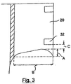
- Figure 3 shows an alternative side section geometry according to the invention, in which the greatest extension A of the lower edge 64 in the longitudinal direction 28 is to be measured between the outer edge 61 and the inner edge 60, since the contour of the lower edge 64 has a real maximum.
- A is in the case shown Figures 2a , 2 B 55 mm, B is 225 mm, R is 0.24.
- the length D of the inner edge 50 is 350 mm.
- the pull-out strength of the rear side sections is 64.5 N.
- the side section pull-out strength of a comparison diaper was determined, which was made of identical materials and had an identical maximum side section length and width, but with side sections of rectangular contour (as shown schematically in WO2005102241 ) was equipped. Only the basis weight of the PP spun-bonded nonwoven (manufacturer: Pegas as) of the rear side sections was slightly 30 g / m 2 , that is 3 g / m 2 heavier than that of the side sections of the diaper according to the invention described above. The side section pull-out strength of this comparison diaper was only 38.8 N. This shows that even a slight contouring, expressed by a low R-value, has a clearly positive influence on the side section pull-out strength.
- the tear strength is and is determined as tear strength according to the test method specified in DIN EN ISO 13937-2. Deviating from this, the sample length is 150 mm. The central incision has a depth of 50mm. The rate of deformation is set to 200 mm / min. The evaluation is carried out by means of an electronic device. In deviation from DIN EN ISO 13937-2, a peak value to be evaluated is characterized by an increase or decrease in force of at least 0.2 N. Upper and lower force peaks are thus taken into account when determining the Fm.sp. In addition to the arithmetic mean value of the force peaks F m, sp, the maximum value of all upper force peaks of a respective test specimen Fsp and the mean force Fm calculated over the entire force curve to be evaluated are also determined.
- Figure 3 shows a graphical representation of determined tear propagation strengths of spunbonded nonwoven materials forming side sections, which differ from one another only in terms of basis weight.
- the side section tear-off strengths of incontinence disposable diapers according to the invention produced therefrom decrease with decreasing tear resistance of the side section materials.
- the tested 16 g / m 2 spunbonded fabric with a tear resistance of Fm 4.48 in combination with the contouring of the side sections according to the invention also meets the requirements for the tear resistance of the side sections when using the diaper, even if the closure means less than 5 cm from the lower edge of the side sections are attached by the manufacturer.
- Figure 5 shows schematically a section of the method according to the invention for producing the disposable incontinence diaper.
- the web is guided by a transfer roller 1000 for removing the cut waste 62, which is arranged downstream of the knife rollers (not shown at point 74) for contouring the leg opening areas 50 on both sides and by means of which the connected cut waste 62 from the rear side section and main part can be removed from the process.
- the transfer roller 1000 has pin-shaped mechanical elements 1020 arranged in a zoned manner for gripping the cutting waste 62.
- the cut waste can be sucked off in particular after it has been gripped by the transfer roller 1000 by means of a suction device 1010 which is only indicated.
- Figure 6 shows schematically, not to scale, the extension l 5 of the cutting waste 62 in the transverse direction of preferably 150 mm-350 mm, in particular 190 mm-300 mm.
- the extension l 3 of the section 62c of the section waste separated from the main part in the longitudinal direction is preferably 110 to 500 mm, in particular 200 to 450 mm.
- the transverse extent l 4 of the section 62c of the section waste separated from the main part is 5 to 100 mm, in particular 8 to 70 mm, further in particular 10 to 60 mm.
- the greatest longitudinal extent l 1 of the region 62a separated from the rear and / or front side section is 20 to 180 mm, in particular 30 to 100 mm.
- a disposable incontinence diaper is cut (punched or cut) 60 cm below the rear side portion, destroying the main part.
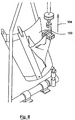
- the test specimen containing the lower side section is clamped in the tensile tester (see Figures 7 and 8th ).
- test specimen is placed with its inside against and over a curved surface 100 (radius of curvature 19 cm), which is intended to simulate the curvature of the back area of a user and clamped into the device of the tensile tester (see Figures 7 and 8th ).
- a curved surface 100 radius of curvature 19 cm
- the test of a right rear side section is shown.
- a test device and arrangement arranged in mirror image is provided.
- the product is to be clamped in the device in such a way that the test specimen is fixed by the fixed clamp 101 over the entire length of the test specimen at a distance (transverse direction) of 60 mm from the inner edge of the side section 20.
- the movable clamp 102 is fixed at the lower end of the outer edge of the side section 20 over a length of 60 mm and a width of 30 mm.
- the curved surface 100 is tilted forward (inclined) so that the side section can lie against the curved surface during the subsequent tensile test (see Figure 8 ).
- a tensile test is carried out by controlled movements of the movable clamp 102 in the direction of the arrow 104.
- the test speed at which the movable clamp 102 is mechanically moved away from the main part of the incontinence product is 1800 mm / min.
- a preload of 0.2 N (Newton) is applied.
- the measured maximum forces are averaged in [N] of each tensile test.
Description
Die Erfindung betrifft einen absorbierenden Inkontinenzartikel des offenen Typs mit einem Hauptteil, bestehend aus einem Vorderbereich, einem Rückenbereich und einem in Längsrichtung dazwischen liegenden zwischen den Beinen eines Benutzers zu liegen kommenden Schrittbereich, wobei der Hauptteil einen Saugkörper umfasst, und mit an den Rückenbereich und/oder an den Vorderbereich beidseits angefügten, voneinander separaten mit Verschlussmitteln versehenen Seitenabschnitten, welche sich in Querrichtung über seitliche Längsränder des Hauptteils hinaus erstrecken und den Vorderbereich und den Rückenbereich im angelegten Zustand des Artikels miteinander verbinden.The invention relates to an absorbent incontinence article of the open type with a main part, consisting of a front area, a back area and a crotch area lying between the legs of a user in the longitudinal direction, the main part comprising an absorbent body, and with the back area and / or to the front area attached on both sides, separate side sections provided with closure means, which extend in the transverse direction beyond the lateral longitudinal edges of the main part and connect the front area and the back area to one another in the applied state of the article.
Derartige Inkontinenzartikel sind bekannt und beispielsweise in
Die aus der Fertigungssicht effizienteste und einfachste sowie kostengünstigste Form der Seitenabschnitte ist die rechteckige Form. Sie erlaubt bei der Herstellung den Transport der die Seitenabschnitte bildenden Materialien in Form einer endlosen Flachmaterialbahn,von der dann die Seitenabschnitte quer zur Maschinenrichtung abgetrennt werden. Ein Schnittabfall ist hier praktisch nicht gegeben.From the production point of view, the most efficient, simplest and cheapest form of the side sections is the rectangular form. During manufacture, it allows the materials forming the side sections to be transported in the form of an endless sheet of flat material, from which the side sections are then cut off transversely to the machine direction. There is practically no cut waste here.
Es hat sich jedoch gezeigt, dass insbesondere bei der Ausbildung der Seitenabschnitte in der ansonsten vorteilhaften Rechteckform beim Anlegen und Tragen des Hygieneartikels mitunter das Problem besteht, dass die angefügten hinteren Seitenabschnitte im Bereich der seitlichen Längsränder des Hauptteils einreißen können. Es hat sich nämlich gezeigt, dass Anwender beim Anlegen des Hygieneartikels geneigt sind, einen zur Quer- und Längsrichtung des Hygieneartikels schrägen Zug auf die hinteren Seitenabschnitte auszuüben, was in
Ein weiterer aus dem Stand der Technik bekannter Vorschlag ist, die Seitenabschnitte mit einem Verstärkungsmittel zu versehen, welches in Querrichtung betrachtet schmäler ausgebildet ist als ein jeweiliger Seitenabschnitt und welches wenigstens in einem den seitlichen Längsrand des Hauptteils überbrückenden Bereich vorgesehen ist, also sowohl einen seitlichen Längsrandbereich des Hauptteil als auch einen Teil des Seitenabschnitts in Querrichtung überfängt (
Der vorliegenden Erfindung liegt die Aufgabe zugrunde, das vorstehend geschilderte Problem noch effektiver zu lösen, also absorbierende Inkontinenzartikel mit vorn und hinten jeweils zwei seitlich angestückten und angefügten Seitenabschnitten zu schaffen, bei denen das Ausreißverhalten der hinteren Seitenabschnitte signifikant verbessert ist.The present invention is based on the object of solving the above-described problem even more effectively, that is to create absorbent incontinence articles with front and rear two side sections attached and attached, in which the pull-out behavior of the rear side sections is significantly improved.
Diese Aufgabe wird durch einen absorbierenden Inkontinenzartikel mit den Merkmalen des Anspruchs 1 gelöst. Hierbei werden R, Fm und C wie weiter unten beschrieben ermittelt.This object is achieved by an absorbent incontinence article with the features of claim 1. R, Fm and C are determined as described below.
Wie unten noch näher erläutert und nachgewiesen werden wird, hat bereits die Konturierung der hinteren Seitenabschnitte zur Folge, dass die Seitenabschnittsausreißfestigkeit signifikant erhöht wird, da bei der konturierten Form der Seitenrand des Hauptteils weniger geeignet ist, eine Art Abreißkante für die Seitenabschnitte zu bilden. Außerdem wird die Zugkraft, die beim Anlegen der Windel über die beinöffnungsnahen Verschlussmittel in den Seitenabschnitt eingeleitet wird, auf eine größere Fläche verteilt, so dass die auf den kritischen Punkt einwirkende resultierende Kraft deutlich vermindert ist. Unter dem kritischen Punkt wird der Punkt verstanden, an dem der untere Rand des Seitenabschnitts den hinteren Seitenrand des Hauptteils trifft.As will be explained and demonstrated in more detail below, the contouring of the rear side sections already has the consequence that the side section pull-out strength is significantly increased, since with the contoured shape the side edge of the main part is less suitable for forming a kind of tear-off edge for the side sections. In addition, the tensile force that is introduced into the side section when the diaper is put on via the closure means near the leg opening is distributed over a larger area, so that the resulting force acting on the critical point is significantly reduced. The critical point is the point at which the lower edge of the side section meets the rear side edge of the main part.
Bereits ein sehr geringes Längen- zu Breitenverhältnis R = A/B der Seitenabschnittsbeinöffnungsbereiche ist hinreichend, um diesbezüglich einen signifikant positiven Effekt auszuüben. Ein Wert R von größer 0,4 würde der Passform sowie dem Anlegekomfort der Inkontinenzwegwerfwindel hingegen abträglich sein und außerdem die Menge des zu verwerfenden Schnittabfalls erhöhen.A very small length to width ratio R = A / B of the side section leg opening areas is sufficient to have a significantly positive effect in this regard. A value R of greater than 0.4 would, however, be detrimental to the fit and the comfort of the disposable incontinence diaper and would also increase the amount of cut waste to be discarded.
Es wurde weiterhin erkannt, dass die Weiterreißfestigkeit des die hinteren Seitenabschnitte bildenden Materials von lediglich mindestens 4.0 N kombiniert mit der erfindungsgemäßen Konturierung der hinteren Seitenabschnitte gestattet, die Verschlussmittel sehr dicht, das heißt höchstens 5 cm davon beabstandet an den unteren Rand der hinteren Seitenabschnitte zu positionieren. Es wurde zwar erkannt, dass die oben beschriebene Gefahr des Einreißens der hinteren Seitenabschnitte entlang der seitlichen Längsränder des Hauptteils mit der Entfernung der Verschlussmittel von dem unteren Rand der Seitenabschnitte abnimmt; gleichzeitig ginge damit jedoch ein erheblicher Verlust an Komfort einher, die Windel mit den sehr weit in Windellängs- und -querrichtung ausladenden Seitenabschnitten passgenau an einer Person anzulegen. Das passgenaue Anlegen der Windel lässt sich mit sehr dicht an dem unteren Rand der Seitenabschnitte positionierten Verschlussmittel wesentlich einfacher bewerkstelligen, da hierdurch über die Verschlussmittel ein Zug auf nahezu die gesamte Seitenabschnittslänge ausgeübt werden kann. Überraschenderweise löst die Erfindung diesen noch nicht bekannten Zielkonflikt durch die im Anspruch 1 spezifizierte Merkmalskombination. Die vorliegende Erfindung ermöglicht überdies, ein hohes Maß an Flexibilität bei der Auswahl der Materialien für die hinteren Seitenabschnitte, da hierdurch auch Materialien mit hohem Tragekomfort jedoch geringer Zugfestigkeit (tensile strength), eingesetzt werden können.It was also recognized that the tear resistance of the material forming the rear side sections of only at least 4.0 N combined with the contouring of the rear side sections according to the invention allows the closure means to be positioned very tightly, that is to say at most 5 cm apart, at the lower edge of the rear side sections. It was recognized that the risk of tearing of the rear side sections described above along the lateral longitudinal edges of the main part decreases with the removal of the closure means from the lower edge of the side sections; at the same time, however, this would entail a considerable loss of comfort in fitting the diaper with the side sections that protrude very far in the longitudinal and transverse directions of the diaper to a person. The exact fitting of the diaper can be accomplished much more easily with closure means positioned very close to the lower edge of the side portions, since this allows a pull to be exerted over almost the entire length of the side portion. Surprisingly, the invention resolves this as yet unknown goal conflict by the combination of features specified in claim 1. The present invention also enables a high degree of flexibility in the selection of materials for the rear side sections, since it also allows materials with a high level of comfort but low tensile strength to be used.
Zwar sind gattungsgemäße Inkontinenzwindeln mit schräg zur Längsrichtung verlaufenden oder kurvenförmig ausgebildeten Seitenabschnitten bereits bekannt (
In besonders bevorzugter Weise weist der Hauptteil im Schrittbereich ebenfalls eine Konturierung auf. Vorteilhafterweise werden die schräg zur Längsrichtung verlaufend oder kurvenförmig ausgebildeten Seitenabschnittsbeinöffnungsbereiche durch einen kontinuierlich oder quasikontinuierlich geführten Abtrennvorgang, insbesondere durch einen Schnitt oder eine Stanzung, gebildet, so dass ein stetiger durchgehender Rand gebildet wird. Die Bahn des Abtrennvorgangs erfasst dabei den hinteren Seitenabschnitt und vorzusgweise auch den Hauptteil. Die konturierten Beinöffnungsbereiche sind somit ausschließlich durch Schnitt- oder Trennkanten des einzigen, kontinuierlichen oder quasikontinuierlichen Abtrennvorgangs gebildet, was natürlich auch eine wirtschaftliche Herstellbarkeit der Inkontinenzwegwerfwindel impliziert und unerwünschte Kanten vermieden werden.In a particularly preferred manner, the main part also has a contour in the crotch area. Advantageously, the side-section leg opening regions, which run obliquely to the longitudinal direction or are curved, are formed by a separation process which is carried out continuously or quasi-continuously, in particular by means of a cut or a stamping, so that a continuous, continuous edge is formed. The path of the separation process covers the rear side section and preferably also the main part. The contoured leg opening areas are thus formed exclusively by cut or separating edges of the single, continuous or quasi-continuous separation process, which of course also implies an economical manufacture of the disposable incontinence diaper and undesirable edges are avoided.
Bei diesem Abtrennvorgang muss der von dem hinterem Seitenabschnitt und gegebenenfalls von dem Hauptteil gebildete zusammenhängende Schnittabfall aus dem Prozess abgeführt werden. Dies erfolgt vorteilhaft nach dem in
Die Erstreckung l3 des vom Hauptteil abgetrennten Bereichs des Schnittabfalls in Längsrichtung der Inkontinenzwegwerfwindel beträgt vorzugsweise 110 bis 500 mm, insbesondere 200 bis 450 mm; hingegen ist die größte Quererstreckung l4 dieses vom Hauptteil abgetrennten Bereichs eher gering, sie beträgt vorzugsweise 5 bis 100, insbesondere 8 bis 70 und weiter insbesondere 10 bis 60 mm.The extent l 3 of the area of the cut waste separated from the main part in the longitudinal direction of the disposable incontinence diaper is preferably 110 to 500 mm, in particular 200 to 450 mm; on the other hand, the greatest transverse extension l 4 of this area separated from the main part is rather small, it is preferably 5 to 100, in particular 8 to 70 and further in particular 10 to 60 mm.
Die Erstreckung l5 des Schnittabfalls in der genannten Querrichtung beträgt insbesondere 150 bis 350 mm und weiter insbesondere 190 bis 300 mm.The extent l 5 of the cutting waste in the transverse direction mentioned is in particular 150 to 350 mm and further in particular 190 to 300 mm.
In weiterer Ausbildung der Erfindung wird vorgeschlagen, dass das Längen- zu Breitenverhältnis R = A/B der hinteren Seitenabschnittsbeinöffnungsbereiche mindestens 0,15, vorzugsweise 0,18-0,35, besonders bevorzugt 0,20-0,32 beträgt.In a further embodiment of the invention it is proposed that the length to width ratio R = A / B of the rear side leg opening areas is at least 0.15, preferably 0.18-0.35, particularly preferably 0.20-0.32.
Nach einem weiteren Erfindungsgedanken beträgt der Abstand C der Verschlussmittel von dem unteren, dem Schritt zugewandten Rand der hinteren Seitenabschnitte höchstens 4,0 cm, vorzugsweise höchstens 3,5 cm, besonders bevorzugt höchstens 3 cm und ganz besonders mindestens 0,5 cm.According to a further inventive concept, the distance C of the closure means from the lower edge of the rear side sections facing the step is at most 4.0 cm, preferably at most 3.5 cm, particularly preferably at most 3 cm and very particularly at least 0.5 cm.
Das Flächengewicht des die hinteren Seitenabschnitte bildenden Materials sollte vorzugsweise 14-40 g/m2 insbesondere 16-30 g/m2 und ganz besonders 17-28 g/m2 betragen.The weight per unit area of the material forming the rear side sections should preferably be 14-40 g / m 2, in particular 16-30 g / m 2 and very particularly 17-28 g / m 2 .
Die Weiterreißfestigkeit des die hinteren Seitenabschnitte bildenden Materials gemessen und ermittelt als mittlere Kraft Fm wie unten näher beschrieben beträgt vorzugsweise mindestens 5,0 N, besonders bevorzugt mindestens 6,0 N und ganz besonders bevorzugt mindestens 6,5 N, vorzugsweise jedoch höchstens 10,0 N.The tear propagation resistance of the material forming the rear side sections and determined as the average force Fm as described in more detail below is preferably at least 5.0 N, particularly preferably at least 6.0 N and very particularly preferably at least 6.5 N, but preferably at most 10.0 N.
Die Weiterreißfestigkeit des die hinteren Seitenabschnitte bildenden Materials gemessen und ermittelt als Mittelwert der Kraftspitzen Fm.sp wie unten näher beschrieben beträgt vorzugsweise mindestens 5,5 N, besonders bevorzugt mindestens 6,0 N, ganz besonders bevorzugt mindestens 6,5 N und insbesondere mindestens 7,0 N, vorzugsweise jedoch höchstens 12 N.The tear propagation strength of the material forming the rear side sections and measured as the mean value of the force peaks Fm.sp as described in more detail below is preferably at least 5.5 N, particularly preferably at least 6.0 N, very particularly preferably at least 6.5 N and in particular at least 7 .0 N, but preferably at most 12 N.
Die Weiterreißfestigkeit des die hinteren Seitenabschnitte bildenden Materials gemessen und ermittelt als maximale Spitzenkraft Fsp wie unten näher beschrieben beträgt vorzugsweise mindestens 5,5 N, besonders bevorzugt mindestens 6,0 N, ganz besonders bevorzugt mindestens 6,5 N und insbesondere mindestens 7,0 N, vorzugsweise jedoch höchstens
12 N.The tear propagation resistance of the material forming the rear side sections and determined as the maximum peak force Fsp as described in more detail below is preferably at least 5.5 N, particularly preferably at least 6.0 N, very particularly preferably at least 6.5 N and in particular at least 7.0 N , but preferably at most
12 N.
In weiterer Weiterbildung der Erfindung hat es sich als vorteilhaft erwiesen, auch die vorderen Seitenabschnitt mit einem Flächengewicht wie oben für die hinteren Seitenabschnitte beschrieben zu versehen. Vorzugsweise weisen außerdem auch die vorderen Seitenabschnitte eine Weiterreißfestigkeit Fm und/oder Fm,sp und/oder Fsp wie für die hinteren Seitenabschnitte beschrieben auf.In a further development of the invention, it has proven to be advantageous to provide the front side sections with a basis weight as described above for the rear side sections. Preferably the front side sections also have a tear strength Fm and / or Fm, sp and / or Fsp as described for the rear side sections.
Nach einer bevorzugten Ausführungsform der Erfindung verlaufen ein innerer Rand und äußerer Rand der vorderen und/oder hinteren Seitenabschnitte parallel zueinander. Weiter bevorzugt verläuft der innere Rand zumindest abschnittsweise parallel zu einer Längsrichtung der Inkontinenzwegwerfwindel. Vorzugsweise weist der innere Rand der hinteren Seitenabschnitte eine größere Erstreckung D in der Längsrichtung auf als der äußere Rand.According to a preferred embodiment of the invention, an inner edge and outer edge of the front and / or rear side sections run parallel to one another. More preferably, the inner edge runs at least in sections parallel to a longitudinal direction of the disposable incontinence diaper. The inner edge of the rear side sections preferably has a greater extension D in the longitudinal direction than the outer edge.
Es hat sich weiter als vorteilhaft erwiesen, die vorderen und/oder hinteren Seitenabschnitte aus einem Vliesstoffmaterial zu bilden. Geeignet sind insbesondere alle Vliesstoffmaterialien, die zumindest eine Rezepturkomponente auf Basis eines thermoplastischen Polymers enthalten. Die Vliesstoffe können Fasern aus PE, PP, PET, Rayon, Cellulose, PA und Mischungen dieser Fasern enthalten. Auch Bi- oder Multikomponentenfasern sind denkbar und vorteilhaft. Vorteilhaft sind insbesondere Kardenvliese, Spinnvliese, wasserstrahlvernadelte Vliese, SM-Vliese, SMS-Vliese, SMMS-Vliese oder auch Laminate aus einer oder mehreren dieser Vliesarten, wobei S für Spunbond- und M für Meltblown-Vliesschichten steht. Denkbar und vorteilhaft ist des Weiteren, die vorderen und/oder hinteren Seitenabschnitte aus einem Vliesstoff-Folienlaminat zu bilden, Solchenfalls würde die Folienkomponente außen zu liegen kommen und die Vliesstoffkomponente innen, um körperzugewandt eine weiche Oberfläche zu gewährleisten. In Weiterbildung dieses Erfindungsgedankens ist vorteilhaft, die vorderen und/oder hinteren Seitenabschnitte aus einem Vliesstoff-Folie-Vliesstofflaminat zu bilden, bei dem eine Folienkomponente sandwichartig zwischen zwei Vlieskomponenten angeordnet ist.It has also proven to be advantageous to form the front and / or rear side sections from a nonwoven material. All nonwoven materials that contain at least one formulation component based on a thermoplastic polymer are particularly suitable. The nonwovens can contain fibers made of PE, PP, PET, rayon, cellulose, PA and mixtures of these fibers. Bicomponent or multicomponent fibers are also conceivable and advantageous. Particularly advantageous are carded nonwovens, spunbonded nonwovens, water-jet needled nonwovens, SM nonwovens, SMS nonwovens, SMMS nonwovens or also laminates of one or more of these types of nonwovens, where S stands for spunbond and M for meltblown nonwoven layers. It is also conceivable and advantageous to form the front and / or rear side sections from a nonwoven film laminate. In such a case, the film component would come to lie on the outside and the nonwoven component on the inside in order to ensure a soft surface facing the body. In a further development of this inventive idea, it is advantageous to form the front and / or rear side sections from a nonwoven film-nonwoven laminate, in which a film component is sandwiched between two nonwoven components.
Des Weiteren erweist es sich als vorteilhaft, dass seitlich neben den Längsrändern des Saugkörpers erste elastische Elemente mit einer Komponente in Längsrichtung an den Hauptteil angefügt sind. Diese elastischen Elemente können exakt, das heißt geradlinig in Längsrichtung verlaufen oder besonders vorteilhaft auch einer gewissen Konturierung entlang der Beinöffnungen folgend vorgesehen werden. Die elastischen Elemente nehmen solchenfalls einen gekrümmten Verlauf entlang der Beinöffnung. In besonderer Weiterbildung dieses Erfindungsgedankens ist vorgesehen, dass die elastischen Elemente sich nicht in die Seitenabschnitte hinein erstrecken, sondern auf eine Positionierung innerhalb des Hauptteils limitiert sind. Des Weiteren können in der ersten Längsrichtung erstreckte zweite elastische Elemente, insbesondere in Form von so genannten und an sich zum Beispiel auch aus
In Weiterbildung der Erfindung ist vorgesehen, dass die Verschlussmittel zum bestimmungsgemäßen Festlegen der Inkontinenzwegwerfwindel an den Körper eines Menschen zumindest bereichsweise sowohl an der Außenseite des Hauptteils als auch an der Außenseite der vorderen Seitenabschnitte lösbar festlegbar sind, wobei die Haltekräfte zwischen den Verschlussmitteln und der Außenseite der vorderen Seitenabschnitte vorzugsweise größer sind als die Haltekräfte zwischen den Verschlussmitteln und der Außenseite des Hauptteils. Dies veranlasst den Benutzer in der Mehrzahl der Fälle, die Verschlussmittel an den vorderen Seitenabschnitten festzulegen. Die Haltekräfte als Über-Bauch-Haltekräfte ermittelt zwischen den insbesondere mechanischen Verschlusshilfen aufweisenden Verschlussmitteln und der Außenseite des Hauptteils betragen vorzugsweise 20-57 N/25mm, insbesondere 25-50 N/25mm. Des Weiteren betragen die Über-Bauch-Haltekräfte zwischen den Verschlussmitteln und der Außenseite der Seitenteile im Vorderbereich vorzugsweise 58-90 N/mm, insbesondere 60-80 N/25mm. Des Weiteren erweist es sich als vorteilhaft, wenn die Über-Bauch-Haltekräfte zwischen den Verschlussmitteln und der Außenseite der hinteren Seitenabschnitte geringer sind als die Über-Bauch-Haltekräfte zwischen den Verschlussmitteln und der Außenseite der vorderen Seitenabschnitte. Auch dies veranlasst den Benutzer in der Mehrzahl der Fälle, die Verschlussmittel an den vorderen Seitenabschnitten festzulegen. Im Rahmen der vorliegenden Erfindung wurden die Über-Bauch-Haltekräfte nach der in
Die Außenseite des Hauptteils der Inkontinenzwegwerfwindel wird vorzugsweise zumindest bereichsweise, insbesondere aber vollflächig durch einen Vliesstoff gebildet. Dies vermittelt der Inkontinenzwegwerfwindel einen "textile-like" Eindruck. Solchenfalls ist es vorteilhaft, das Backsheet des Hauptteils aus einem Vliesfolienlaminat zu bilden, wobei die Vlieslage außen und die Folienlage innen zum Saugkörper gerichtet zu liegen kommt, so dass die Vlieslage die Außenseite des Hauptteils bildet. Damit ist zum einen die Flüssigkeitsundurchlässigkeit des Hauptteils sichergestellt und zum anderen der hautfreundliche Charakter der Windel gesichert. Die Folienlage dieses Vliesfolienlaminates ist dann vorzugsweise aus einer ein- oder mehrschichtigen flüssigkeitsundurchlässigen, vorzugsweise aber gleichwohl atmungsaktiven Folie gebildet, wobei die Atmungsaktivität der vorderen und/oder der hinteren Seitenabschnitte vorzugsweise größer ist als die Atmungsaktivität des das Backsheet der Inkontinenzwegwerfwindel bildenden Vliesfolienlaminates.The outside of the main part of the disposable incontinence diaper is preferably formed at least in regions, but in particular over the entire area, by a nonwoven fabric. This gives the disposable incontinence diaper a "textile-like" impression. In such a case, it is advantageous to form the backsheet of the main part from a nonwoven film laminate, the nonwoven layer being on the outside and the film layer on the inside facing the absorbent body, so that the nonwoven layer forms the outside of the main part. This ensures, on the one hand, that the main part is impermeable to liquids and, on the other hand, ensures that the diaper is skin-friendly. The film layer of this nonwoven film laminate is then preferably formed from a single-layer or multilayer liquid-impermeable, but preferably nevertheless breathable film, the breathability of the front and / or rear side sections preferably being greater than the breathability of the nonwoven film laminate forming the backsheet of the disposable incontinence diaper.
Der Saugkörper des Hauptteils umfasst vorzugsweise Fasermaterialien, insbesondere Zellulosefasern, weiter insbesondere natürliche Zellulosefasern wie Zellstofffluff. Vorteilhaft enthält der Saugkörper superabsorbierende Materialien (SAP) insbesondere in Partikel- oder Faserfom, also Materialien welche ein Vielfaches, vorzugsweise mindestens das 20-fache, insbesondere mindestens das 30-fache ihres Eigengewichts an wässrigen Flüssigkeiten, insbesondere an 0,9 %-iger NaCl-Lösung absorbieren können, gemessen nach EDANA ERT 440.2-02.The absorbent body of the main part preferably comprises fiber materials, in particular cellulose fibers, further especially natural cellulose fibers such as cellulose fluff. The absorbent advantageously contains superabsorbent materials (SAP), in particular in particle or fiber form, i.e. materials which have a multiple, preferably at least 20 times, in particular at least 30 times their own weight of aqueous liquids, in particular 0.9% NaCl - Can absorb solution, measured according to EDANA ERT 440.2-02.
Vorteilhaft unterscheiden sich die hinteren Seitenabschnitte von den vorderen Seitenabschnitten bezüglich mindestens einer, insbesondere mindestens zweier, weiter insbesondere mindestens dreier und weiter insbesondere mindestens vierer ihrer Primäreigenschaften ausgewählt aus der Gruppe Art des Materials, Flächengewicht, Atmungsaktivität, Dichte, Dehnbarkeit, Verschlusskraft, Flächenerstreckung, Dicke, Farbe. Diesbezüglich wird hiermit ausdrücklich auf den Offenbarungsgehalt der
In Weiterbildung der Erfindung erweist es sich als vorteilhaft, wenn die Länge der vorderen und/oder hinteren Seitenabschnitte, also deren maximale Erstreckung in Windellängsrichtung mindestens 10 cm, insbesondere mindestens 15 cm, weiter insbesondere mindestens 18 cm, weiter insbesondere mindestens 22 cm und weiter insbesondere höchstens 45 cm beträgt. Vorteilhafterweise beträgt die Gesamtlänge der Inkontinenzwegwerfwindel 50-120 cm, insbesondere 60-110 cm und weiter insbesondere 70-110 cm. In Weiterbildung der Erfindung erweist es sich als vorteilhaft, wenn die Breite der vorderen und/oder hinteren Seitenabschnitte, also die maximale Erstreckung der Seitenabschnitte über den Seitenrand des Windelhauptteils hinaus 10-40 cm, insbesondere 12-30 cm, weiter insbesondere 13-25 cm beträgt. Vorzugsweise weisen die vorderen Seitenabschnitte die gleiche Breite auf wie die hinteren Seitenabschnitte.In a development of the invention, it proves to be advantageous if the length of the front and / or rear side sections, i.e. their maximum extension in the longitudinal direction of the diaper, is at least 10 cm, in particular at least 15 cm, further in particular at least 18 cm, further in particular at least 22 cm and further in particular is at most 45 cm. The total length of the disposable incontinence diaper is advantageously 50-120 cm, in particular 60-110 cm and further in particular 70-110 cm. In a development of the invention, it proves to be advantageous if the width of the front and / or rear side sections, that is to say the maximum extension of the side sections beyond the side edge of the main diaper part, is 10-40 cm, in particular 12-30 cm, further particularly 13-25 cm is. The front side sections preferably have the same width as the rear side sections.
Die Erfindung betrifft außerdem ein Verfahren zum Herstellen einer Inkontinenzwegwerfwindel, wobei zur Konturierung der beidseitigen Beinöffnungsbereiche der Inkontinenzwegwerfwindel beidseits je ein kontinuierlich oder quasikontinuierlich geführter, den hinteren mit Verschlussmitteln bereits versehenen Seitenabschnitt und den Hauptteil erfassender Abtrennvorgang ausgeführt wird, so dass von hinterem Seitenabschnitt und Hauptteil ein zusammenhängender Schnittabfall gebildet wird, der abgeführt werden muss, und wodurch der Abstand C der Verschlussmittel vom unteren Rand der hinteren Seitenabschnitte resultiert.The invention also relates to a method for producing a disposable incontinence diaper, in order to contour the bilateral leg opening areas of the disposable incontinence diaper on each side, a continuous or quasi-continuous removal process, which already includes the rear side section provided with closure means and the main part, is carried out, so that a rear side section and main part are carried out coherent cut waste is formed, which must be removed, and which results in the distance C of the closure means from the lower edge of the rear side portions.
In Weiterbildung dieses Verfahrens ist vorgesehen, dass der Schnittabfall von einer Transferwalze mit von ihrer Oberfläche vorstehenden stift-, noppen-, haken- oder widerhakenförmigen mechanischen Elementen ergriffen und abgeführt wird.In a further development of this method it is provided that the cut waste is gripped and removed by a transfer roller with mechanical, pin-shaped, knob-shaped, hook-shaped or barb-shaped elements protruding from its surface.
Vorzugsweise wird zum Ergreifen des Schnittabfalls außerdem eine Unterdruckunterstützung bei der Transferwalze verwendet.A vacuum support in the transfer roller is preferably also used to grasp the cut waste.
Das erfindungsgemäße Verfahren wird vorteilhaft außerdem dadurch weitergebildet, dass die Erstreckung l5 des Schnittabfalls (vgl.
In der Zeichnung zeigen:
-
Figur 1 eine Draufsicht auf einen Inkontinenzartikel in schematischer Darstellung mit beidseits angefügten Seitenabschnitten; -
Figuren 2a und2b je eine vergrößerte Teilansicht der Inkontinenzwegwerfwindel nachFigur 1 ; -
Figur 3 beispielhaft eine weitere erfindungsgemäße Seitenabschnittsgeometrie; -
Figur 4 -
Figur 5 eine perspektivische Ansicht der Bahnführung über eine Transferwalze mit vorstehenden mechanischen Elementen zum Abführen des Schnittabfalls; -
Figur 6 -
Figuren 7 und8 eine Darstellung der Prüfung der Seitenabschnittsausreißfestigkeit.
-
Figure 1 a plan view of an incontinence article in a schematic representation with side sections attached on both sides; -
Figures 2a and2 B each an enlarged partial view of the disposable incontinence diaperFigure 1 ; -
Figure 3 another side section geometry according to the invention by way of example; -
Figure 4 a graphic representation of determined tear strength; -
Figure 5 a perspective view of the web guide over a transfer roller with protruding mechanical elements for removing the cut waste; -
Figure 6 a representation of a separated section waste; -
Figures 7 and8th a representation of the test of the side section tear strength.
Unter vorderen und hinteren seitlichen Längsrändern 42, 41 des Hauptteils werden im Rahmen der vorliegenden Erfindung diejenigen Längsrandbereiche des Hauptteils verstanden, an die die Seitenabschnitte angefügt sind und über welche diese sich hinaus erstrecken. Die Längserstreckung der vorderen und hinteren Seitenränder des Hauptteils 42, 41 definieren damit auch die Längserstreckung des Vorderbereiches 6 und des Rückenbereiches 8 der Inkontinenzwegwerfwindel 2.In the context of the present invention, front and rear lateral
Es wird hiermit außerdem klargestellt, dass die Begriffe "Seitenrand" und "seitlicher Längsrand" vor- und nachstehend synonym verwendet werden.It is also hereby clarified that the terms "side margin" and "lateral longitudinal margin" are used synonymously before and below.
Die Seitenabschnitte 20, 22 sind dafür gedacht und bestimmt, im angelegten Zustand der Inkontinenzwegwerfwindel 2 miteinander verbunden zu werden, um einen in Umfangsrichtung durchgehenden Hüftbereich des Hygieneartikels zu bilden. Dabei werden jeweils die auf einer Seite des Hauptteils 4 vorgesehenen Seitenabschnitte 20, 22 miteinander verbunden. Hierzu sind an den hinteren Seitenabschnitten 20 beinöffnungsnahe mechanische Verschlussmittel 32 und beinöffnungsferne Verschlussmittel 33, insbesondere mit mechanischen Verschlusshilfen wie Kletthaken, vorgesehen, welche auf der Außenseite der vorderen und hinteren Seitenabschnitte 20, 22 lösbar festlegbar sind. Vorzugsweise sind die Verschlussmittel außerdem auf der Außenseite des Hauptteils lösbar festlegbar. Sowohl die vorderen Seitenabschnitte 22 als auch die hinteren Seitenabschnitte 20 sind aus einem Vliesstoffmaterial, im dargestellten Fall aus einem PP-Spinnvlies, Pegatex S, Hersteller: Pegas a.s.,Primetickä 86, 66904 Znojmo, CZ, gebildet. Das Flächengewicht des Vliesstoffmaterials der vorderen Seitenabschnitte beträgt 30 g/m2. Die Faserstärke der das Vliesstoffmaterial bildenden Fasern beträgt 2 dtex. Die Über-Bauch-Haltekräfte zwischen den Verschlussmitteln 32 und der Außenseite der vorderen Seitenabschnitte 22 betragen vorzugsweise mindestens 58 N/25mm.The
Das Flächengewicht des Vliesstoffmaterials der hinteren Seitenabschnitte 20 beträgt im dargestellten Fall 27 g/m2.The weight per unit area of the nonwoven material of the
Die Weiterreißfestigkeiten des Vliesmaterials der hinteren Seitenabschnitte, gemessen in der Längsrichtung 28 beträgt:
- Fm: 7,0 N
- Fm.sp: 7,2 N
- Fsp: 9,8 N.
- Fm: 7.0 N
- Fm.sp: 7.2 N
- Fsp: 9.8 N.
Die Über-Bauch-Haltekräfte zwischen den Verschlussmitteln 32, 33 und der Außenseite der hinteren Seitenabschnitte 20 sind geringer als die Über-Bauch-Haltekräfte zwischen den Verschlussmitteln 32, 33 und der Außenseite der vorderen Seitenabschnitte 22.The over-belly holding forces between the closure means 32, 33 and the outside of the
Wie aus
Die vorderen und hinteren Seitenabschnitte unterscheiden sich damit in zumindest drei ihrer Primäreigenschaften, nämlich dem Flächengewicht, der Verschlusskraft und der Flächenerstreckung.The front and rear side sections thus differ in at least three of their primary properties, namely the weight per unit area, the closing force and the surface extension.
Der Unterschied in der Verschlusskraft zwischen den vorderen und hinteren Seitenabschnitten veranlasst den Benutzer, die Verschlussmittel 32, 33 bevorzugt an den vorderen Seitenabschnitten 22 festzulegen, was der Passform der Windel förderlich ist. Wie
Die Konturierung der hinteren Seitenabschnitte 20 und des Hauptteils 4 ist im dargestellten Fall gebildet durch je, das heißt auf jeder Seite, einen einzigen Schnitt, welcher sowohl die hinteren Seitenabschnitte 20 als auch den Hauptteil 4 erfasst und hierbei stetig durch zu trennendes Seitenrand- oder Hauptteilmaterial hindurchgeführt ist. Die Beinöffnung 50 umfasst somit einen hinteren konturierten Seitenabschnittsbeinöffnungsbereich 51, einen unkonturiert belassenen vorderen Seitenabschnittsbeinöffnungsbereich 52 und einen konturierten Hauptteilbeinöffnungsbereich 53 (
In der
Abstand A ist im Rahmen der vorliegenden Erfindung definiert als die größte Erstreckung des unteren Randes 64 in der Längsrichtung 28. Abstand B ist definiert als die größte Erstreckung des hinteren Seitenabschnitts in der Querrichtung 30, also in Querrichtung die größte Distanz zwischen innerem Rand 60 und äußerem Rand 61, mithin die Seitenabschnittsbreite. Abstand C ist definiert als die in der Längsrichtung 28 zu ermittelnde kürzeste Distanz zwischen einem beinöffnungsnahen Verschlussmittel 32 und dem unteren Rand 64.Distance A is defined in the context of the present invention as the greatest extent of the
A beträgt im dargestellten Fall der
Die Ausreißfestigkeit der hinteren Seitenabschnitte beträgt 64,5 N. Zum Vergleich wurde die Seitenabschnittsausreißfestigkeit einer Vergleichswindel ermittelt, die aus identischen Materialien gefertigt wurde und eine identische maximale Seitenabschnittslänge und -Breite aufwies, jedoch mit Seitenabschnitten rechteckiger Kontur (so wie schematisch dargestellt in
Im Rahmen der vorliegenden Erfindung sind und werden die Seitenabschnittausreißfestigkeiten mittels des weiter unten erläuterten Prüfverfahrens gemessen.In the context of the present invention, the side section pull-out strengths are and are measured by means of the test method explained below.
Im Rahmen der vorliegenden Erfindung sind und werden die Weiterreißfestigkeiten als Weiterreißkraft nach der In DIN EN ISO 13937-2 spezifizierten Prüfmethode ermittelt. Abweichend davon beträgt die Probenlänge 150 mm. Der mittige Einschnitt weist eine tiefe von 50mm auf. Die Verformungsgeschwindigkeit wird auf 200 mm/min eingestellt. Die Auswertung erfolgt mittels einer elektronischen Einrichtung. Abweichend von DIN EN ISO 13937-2 ist ein auszuwertender Spitzenwert durch einen Kraftanstieg oder einen Kraftabfall von mindestens 0,2 N gekennzeichnet. Es werden somit obere und untere Kraftspitzen bei Ermittlung des Fm.sp berücksichtigt. Neben dem arithmetischen Mittelwert der Kraftspitzen F m,sp, werden außerdem der Maximalwert aller oberen Kraftspitzen eines jeweiligen Prüflings Fsp und die über die gesamte auszuwertende Kraftverlaufskurve berechnete mittlere Kraft Fm ermittelt.Within the scope of the present invention, the tear strength is and is determined as tear strength according to the test method specified in DIN EN ISO 13937-2. Deviating from this, the sample length is 150 mm. The central incision has a depth of 50mm. The rate of deformation is set to 200 mm / min. The evaluation is carried out by means of an electronic device. In deviation from DIN EN ISO 13937-2, a peak value to be evaluated is characterized by an increase or decrease in force of at least 0.2 N. Upper and lower force peaks are thus taken into account when determining the Fm.sp. In addition to the arithmetic mean value of the force peaks F m, sp, the maximum value of all upper force peaks of a respective test specimen Fsp and the mean force Fm calculated over the entire force curve to be evaluated are also determined.
Mit der vorliegenden Erfindung ist es somit gelungen, erstmals eine Inkontinenzwegwerfwindel mit an den Hauptteil angefügten vorderen und hinteren Seitenabschnitten bereitzustellen, welche eine in Gebrauch der Windel ausreichende Seitenabschnittsausreißfestigkeit aufweist und zugleich den Anlege- und Tragekomfort der Inkontinenzwegwerfwindel ausreichend berücksichtigt.With the present invention it has thus been possible for the first time to provide a disposable incontinence diaper with front and rear side sections attached to the main part, which has sufficient side section tear-out strength when the diaper is in use and at the same time takes sufficient account of the wearing and wearing comfort of the disposable incontinence diaper.
Eine Inkontinenzwegwerfwindel wird 60 cm unterhalb des hinteren Seitenabschnittes unter Zerstörung des Hauptteils in Querrichtung getrennt (geschnitten oder gestanzt). Der den unteren Seitenabschnitt enthaltende Prüfling wird in das Zugprüfgerät eingespannt (siehe
Der Prüfling wird dabei mit seiner Innenseite anliegend an und über eine gekrümmte Fläche 100 (Radius der Krümmung 19 cm) gelegt, welche die Rundung des Rückenbereichs eines Benutzers simulieren soll und in die Vorrichtung des Zugprüfgeräts eingespannt (siehe
Das Produkt soll dergestalt in die Vorrichtung eingespannt werden, dass der Prüfling durch die feststehende Klemme 101 über die gesamte Länge des Prüflings im Abstand (Querrichtung) von 60mm vom inneren Rand des Seitenabschnitts 20 fixiert wird. Die bewegbare Klemme 102 wird am unteren Ende des äußeren Randes des Seitenabschnittes 20 über eine Länge von 60mm und eine Breite von 30mm fixiert. Die gekrümmte Fläche 100 ist nach vorn gekippt (geneigt), so dass der Seitenabschnitt beim nachfolgenden Zugversuch an die gekrümmte Fläche anliegen kann (siehe
Claims (15)
- Disposable absorbent incontinence diaper (2) of the open type, having a main part (4), comprising a front region (6) having front lateral longitudinal edges (42), a rear region (8) having rear lateral longitudinal edges (41) and a crotch region (10) that is located in between in the longitudinal direction (28) and comes to lie between the legs of a user, wherein the main part (4) comprises an absorbent pad (12), and having rear side portions (20) that are attached to the rear region (8) on both sides and front side portions (22) that are attached to the front region (6) on both sides, said rear and front side portions extending in the transverse direction (30) beyond the lateral front and rear longitudinal edges (42, 41) of the main part (4), and wherein the rear side portions (20) have first closure means (32) which are close to the leg opening and have closure aids and wherein the closure means (32) can be secured in a detachable manner at least on the outer side of the front side portions (22), as a result of which the front region (6) and the rear region (8) can be connected together, wherein the transverse edge (55), facing the crotch region (10), of the front side portions (22) extends parallel to the transverse direction (30) and wherein, in order to form rear side-portion leg-opening regions (51), the rear side portions (20) are formed, at least on the side facing the crotch region (10), in a manner extending obliquely with respect to the longitudinal direction (28) or in a curved manner, and wherein an outer edge (61) of the rear side portions (20) extends parallel to the longitudinal direction (28), characterized in that the length-to-width ratio R of the side-portion leg-opening region (51) of the rear side portions (20) is 0.1-0.4, in that the tear propagation resistance Fm of the material forming the rear side portions is at least 4.0 N in the longitudinal direction of the diaper, and in that the spacing C of the closure means (32) close to the leg opening from the lower edge of the rear side portions is at most 5 cm.
- Disposable absorbent incontinence diaper (2) according to Claim 1, characterized in that the length-to-width ratio R of the side-portion leg-opening region of the rear side portions (20) is at least 0.15, particularly 0.18-0.35 and more particularly 0.20-0.32.
- Disposable absorbent incontinence diaper (2) according to either of the preceding claims, characterized in that the spacing C of the closure means (32) close to the leg opening from the lower edge of the rear side portions is at most 4 cm, particularly at most 3.5 cm, more particularly at most 3.0 cm and more particularly at least 0.5 cm.
- Disposable absorbent incontinence diaper (2) according to one of the preceding claims, characterized in that the rear side portions have at least one further closure means (33) which is remote from the hip and is provided with closure aids.
- Disposable absorbent incontinence diaper (2) according to one of the preceding claims, characterized in that the tear propagation resistance Fm of the material forming the rear side portions is at least 5.0 N, particularly at least 6.0 N, particularly at least 6.5 N and more particularly at most 10 N in the longitudinal direction of the diaper.
- Disposable absorbent incontinence diaper (2) according to one of the preceding claims, characterized in that the tear propagation resistance Fm.sp of the material forming the rear side portions is at least 5.5 N, particularly at least 6.0 N, particularly at least 6.5 N and more particularly at least 7.0 N and more particularly at most 12 N in the longitudinal direction of the diaper.
- Disposable absorbent incontinence diaper (2) according to one of the preceding claims, characterized in that the tear propagation resistance Fsp of the material forming the rear side portions is at least 5.5 N, particularly at least 6.0 N, particularly at least 6.5 N and more particularly at least 7.0 N and more particularly at most 12 N in the longitudinal direction of the diaper.
- Disposable absorbent incontinence diaper (2) according to one of the preceding claims, characterized in that the rear and/or front side portions (20, 22) are formed from a nonwoven material or comprise a nonwoven material.
- Disposable absorbent incontinence diaper (2) according to one of the preceding claims, characterized in that the extent of the rear and/or front side portions (20, 22) beyond the lateral edge of the main part of the diaper is 10-40 cm, particularly 12-30 cm, more particularly 13-25 cm in the transverse direction.
- Disposable absorbent incontinence diaper (2) according to one of the preceding claims, characterized in that the length of the rear side portions (20), that is the extent thereof in the longitudinal direction of the diaper, is at least 10 cm, particularly at least 15 cm, more particularly at least 18 cm and more particularly at least 22 cm and more particularly at most 45 cm.
- Disposable absorbent incontinence diaper (2) according to one of the preceding claims, characterized in that the front side portions (22) have a rectangular contour.
- Method for producing a disposable incontinence diaper (2) according to one of the preceding claims, wherein in order to contour leg-opening regions (50) on both sides of the disposable incontinence diaper (2), a respective continuously or quasi-continuously guided severing process taking in the rear side portion (20), which is already provided with closure means (32), and the main part (4) is executed on each side, so that a coherent offcut (62) which has to be removed is formed from the rear side portion (20) and the main part (4), and as a result of which the spacing C of the closure means (32) close to the leg opening from the lower edge of the rear side portions (20) is produced.
- Method according to Claim 12, characterized in that the offcut (62) is gripped and removed by a transfer roller (1000) having pin-like, nub-like, hook-like or barb-like mechanical elements (1020) that protrude from its surface.
- Method according to Claim 12 or 13, characterized in that in order to grip the offcut (62) use is made of a negative-pressure assistance means at the transfer roller (1000).
- Method according to Claim 12, 13 or 14, characterized in that the extent I5 of the offcut (62) in the transverse direction is 150 mm-350 mm, particularly 190 mm-300 mm, in that the extent I3 in the longitudinal direction of the region 62c of the offcut severed from the main part is from 110 to 500 mm, particularly from 200 to 450 mm, in that the transverse extent I4 of the region 62c of the offcut severed from the main part is from 5 to 100 mm, particularly from 8 to 70 mm, more particularly from 10 to 60 mm, and in that the greatest longitudinal extent I1 of the region 62a severed from the rear side portion is from 20 to 180 mm, particularly from 30 to 100 mm.
Priority Applications (1)
| Application Number | Priority Date | Filing Date | Title |
|---|---|---|---|
| PL10710555T PL2410965T5 (en) | 2009-03-26 | 2010-03-24 | Absorbent disposable incontinence pants comprising side sections |
Applications Claiming Priority (3)
| Application Number | Priority Date | Filing Date | Title |
|---|---|---|---|
| DE200910015041 DE102009015041A1 (en) | 2009-03-26 | 2009-03-26 | Absorbent disposable incontinence diaper with side sections |
| DE102009059886A DE102009059886A1 (en) | 2009-03-26 | 2009-12-21 | Absorbent disposable incontinence diaper, has material with specific resistance formed in longitudinal direction, and closing unit whose distance in vicinity of leg opening from lower edge of rear side section is in specific value |
| PCT/EP2010/001820 WO2010108661A1 (en) | 2009-03-26 | 2010-03-24 | Absorbent disposable incontinence pants comprising side sections |
Publications (3)
| Publication Number | Publication Date |
|---|---|
| EP2410965A1 EP2410965A1 (en) | 2012-02-01 |
| EP2410965B1 EP2410965B1 (en) | 2013-05-01 |
| EP2410965B2 true EP2410965B2 (en) | 2020-03-18 |
Family
ID=42232623
Family Applications (2)
| Application Number | Title | Priority Date | Filing Date |
|---|---|---|---|
| EP10710555.3A Active EP2410965B2 (en) | 2009-03-26 | 2010-03-24 | Absorbent disposable incontinence pants comprising side sections |
| EP10710554.6A Active EP2410964B2 (en) | 2009-03-26 | 2010-03-24 | Absorbent disposable incontinence pants comprising side sections |
Family Applications After (1)
| Application Number | Title | Priority Date | Filing Date |
|---|---|---|---|
| EP10710554.6A Active EP2410964B2 (en) | 2009-03-26 | 2010-03-24 | Absorbent disposable incontinence pants comprising side sections |
Country Status (10)
| Country | Link |
|---|---|
| US (2) | US8821468B2 (en) |
| EP (2) | EP2410965B2 (en) |
| JP (2) | JP5665842B2 (en) |
| CN (2) | CN102365069B (en) |
| AU (2) | AU2010227811B2 (en) |
| DE (1) | DE102009015041A1 (en) |
| ES (2) | ES2417337T5 (en) |
| PL (2) | PL2410964T5 (en) |
| RU (2) | RU2536551C2 (en) |
| WO (2) | WO2010108661A1 (en) |
Families Citing this family (7)
| Publication number | Priority date | Publication date | Assignee | Title |
|---|---|---|---|---|
| DE102010026643A1 (en) | 2010-07-09 | 2012-01-12 | Paul Hartmann Ag | Absorbent disposable incontinence diaper with side sections |
| US8870843B2 (en) * | 2012-08-07 | 2014-10-28 | Sca Hygiene Products Ab | Disposable absorbent product with temporary adhesive attachment and related methods |
| DE102012025437A1 (en) | 2012-12-21 | 2014-07-10 | Paul Hartmann Ag | Absorbent incontinence article with diaper cover and absorbent insert |
| EP2992865B1 (en) | 2014-09-05 | 2019-11-06 | Drylock Technologies N.V. | Absorbent article with aysmmetrical side panels |
| US9758463B1 (en) * | 2014-09-17 | 2017-09-12 | Nippon Shokubai Co., Ltd. | Method for producing vapor composition containing lactic acid |
| EP3811917A1 (en) | 2019-10-21 | 2021-04-28 | Paul Hartmann AG | Absorbent article with soft acquisition component |
| EP3812495A1 (en) | 2019-10-21 | 2021-04-28 | Paul Hartmann AG | Absorbent article with acquisition component |
Citations (4)
| Publication number | Priority date | Publication date | Assignee | Title |
|---|---|---|---|---|
| WO2000035398A1 (en) † | 1998-12-18 | 2000-06-22 | Kimberly-Clark Worldwide, Inc. | Absorbent article with non-irritating refastenable seams |
| WO2005102241A1 (en) † | 2004-04-23 | 2005-11-03 | Paul Hartmann Ag | Absorbent incontinence article |
| US20080208152A1 (en) † | 2005-07-29 | 2008-08-28 | Paul Hartmann Ag | Incontinence Article |
| EP2020215A1 (en) † | 2007-08-02 | 2009-02-04 | Paul Hartmann AG | Absorbent incontinence disposable pads |
Family Cites Families (37)
| Publication number | Priority date | Publication date | Assignee | Title |
|---|---|---|---|---|
| US7026A (en) * | 1850-01-15 | Door-lock | ||
| MA21077A1 (en) | 1986-10-10 | 1988-07-01 | Procter & Gamble | ABSORBENT ARTICLE COMPRISING DOUBLE FLUID RESISTANT CUFFS. |
| JPH0683527B2 (en) | 1987-09-29 | 1994-10-19 | 株式会社日立製作所 | Gas insulated switchgear |
| JPH0422733Y2 (en) * | 1987-12-07 | 1992-05-26 | ||
| JPH04261655A (en) * | 1990-12-31 | 1992-09-17 | Zuikou:Kk | Manufacture of paper diaper |
| US5236430A (en) * | 1991-11-21 | 1993-08-17 | The Procter & Gamble Company | Disposable training pant having fusion-slit side seams |
| CZ286283B6 (en) † | 1993-11-19 | 2000-03-15 | The Procter & Gamble Company | Absorption article |
| US6447497B1 (en) | 1999-11-22 | 2002-09-10 | Kimberly-Clark Worldwide, Inc. | Absorbent article with child resistant refastenable seams |
| JP4261655B2 (en) | 1998-12-18 | 2009-04-30 | 株式会社東芝 | Image reading system |
| US6645190B1 (en) | 1999-11-22 | 2003-11-11 | Kimberly-Clark Worldwide, Inc. | Absorbent article with non-irritating refastenable seams |
| DE19915932A1 (en) * | 1999-04-09 | 2000-10-19 | Freudenberg Carl Fa | Thermoplastic processable polyurethane molding compound |
| PL366061A1 (en) | 2000-08-30 | 2005-01-24 | Kimberly-Clark Worldwide, Inc. | Tear-resistant adhesive/combination bond pattern |
| US20020123730A1 (en) | 2001-03-05 | 2002-09-05 | Popp Robert Lee | Tucked fastener for improved fastener performance |
| SE0102805L (en) | 2001-08-22 | 2003-02-23 | Sca Hygiene Prod Ab | Absorbent article |
| US6854624B2 (en) * | 2002-06-06 | 2005-02-15 | Kimberly-Clark Worldwide, Inc. | Methods for improving product chassis and panel control during folding of garment |
| AU2003262762A1 (en) | 2002-08-22 | 2004-03-11 | Kimberly-Clark Worldwide, Inc. | Absorbent article having dual pattern bonding |
| DE10326022A1 (en) † | 2003-06-02 | 2004-12-23 | Paul Hartmann Ag | Hygiene articles for single use |
| WO2005079720A1 (en) * | 2004-02-23 | 2005-09-01 | Zuiko Corporation | Wearing article and method of manufacturing the same |
| JP5014595B2 (en) * | 2005-06-14 | 2012-08-29 | ユニ・チャーム株式会社 | Disposable pants-type wearing articles |
| JP4678721B2 (en) * | 2005-06-14 | 2011-04-27 | ユニ・チャーム株式会社 | Disposable pants-type wearing articles |
| DE102005032221A1 (en) | 2005-07-09 | 2007-01-18 | Paul Hartmann Ag | A method of making a plurality of elastic bodily fluid-absorbent disposable incontinent diapers |
| DE102005048868A1 (en) * | 2005-10-12 | 2007-04-19 | Paul Hartmann Ag | A method of manufacturing a plurality of incontinence disposable diapers having a diaper body and front and back diaper side panels attached thereto |
| US8114059B2 (en) † | 2005-10-14 | 2012-02-14 | The Procter & Gamble Company | Absorbent article including barrier leg cuff structure and absorbent core with superabsorbent material |
| US7780052B2 (en) | 2006-05-18 | 2010-08-24 | Curt G. Joa, Inc. | Trim removal system |
| CN101466337B (en) | 2006-06-13 | 2012-11-28 | 株式会社瑞光 | Method of manufacturing disposable wearing article |
| DE102006046420A1 (en) | 2006-09-22 | 2008-04-03 | Paul Hartmann Ag | Sanitary articles or surgical drapes or disposable surgical drapes |
| DE102006050971A1 (en) | 2006-10-23 | 2008-04-24 | Paul Hartmann Ag | Absorbing incontinence article for use as sanitary article, has side sections with reinforcing unit considerably formed as sections and provided in area that bypasses edges, where unit catches longitudinal edge area and part of sections |
| PL1915977T3 (en) | 2006-10-27 | 2015-09-30 | Hartmann Paul Ag | Absorbent incontinence article with an improved fastening system |
| JP2008148942A (en) * | 2006-12-18 | 2008-07-03 | Livedo Corporation | Method for manufacturing disposable diaper |
| ES2336841T3 (en) * | 2007-01-02 | 2010-04-16 | Fameccanica.Data S.P.A. | PROCEDURE FOR MANUFACTURING HYGIENIC ITEMS WITH SIDE PANELS. |
| JP5009039B2 (en) * | 2007-04-27 | 2012-08-22 | 大王製紙株式会社 | Disposable paper diapers |
| US8496778B2 (en) | 2007-06-26 | 2013-07-30 | Sca Hygiene Products Ab | Method for manufacturing an absorbent article |
| DE102007055628A1 (en) | 2007-11-21 | 2009-05-28 | Paul Hartmann Aktiengesellschaft | Incontinence article in panty form |
| DE102007063209A1 (en) | 2007-12-20 | 2009-06-25 | Paul Hartmann Aktiengesellschaft | Method for producing incontinence articles in panty form |
| DE102008046358A1 (en) † | 2008-09-09 | 2010-03-11 | Paul Hartmann Ag | Absorbent Incontinence Disposable Diaper |
| DE102008046607A1 (en) | 2008-09-10 | 2010-05-20 | Paul Hartmann Ag | Incontinence article in panty form |
| DE102008056220A1 (en) | 2008-11-06 | 2010-05-12 | Paul Hartmann Ag | A method of making an absorbent disposable incontinence diaper |
-
2009
- 2009-03-26 DE DE200910015041 patent/DE102009015041A1/en not_active Withdrawn
-
2010
- 2010-03-24 JP JP2012501182A patent/JP5665842B2/en active Active
- 2010-03-24 RU RU2011140423/12A patent/RU2536551C2/en active
- 2010-03-24 PL PL10710554T patent/PL2410964T5/en unknown
- 2010-03-24 WO PCT/EP2010/001820 patent/WO2010108661A1/en active Application Filing
- 2010-03-24 ES ES10710555T patent/ES2417337T5/en active Active
- 2010-03-24 US US13/257,984 patent/US8821468B2/en active Active
- 2010-03-24 WO PCT/EP2010/001819 patent/WO2010108660A1/en active Application Filing
- 2010-03-24 AU AU2010227811A patent/AU2010227811B2/en active Active
- 2010-03-24 CN CN201080013950.8A patent/CN102365069B/en active Active
- 2010-03-24 ES ES10710554T patent/ES2424637T5/en active Active
- 2010-03-24 EP EP10710555.3A patent/EP2410965B2/en active Active
- 2010-03-24 RU RU2011140422/12A patent/RU2531885C2/en active
- 2010-03-24 CN CN201080013949.5A patent/CN102395341B/en active Active
- 2010-03-24 US US13/257,983 patent/US9050214B2/en active Active
- 2010-03-24 AU AU2010227812A patent/AU2010227812B2/en active Active
- 2010-03-24 EP EP10710554.6A patent/EP2410964B2/en active Active
- 2010-03-24 PL PL10710555T patent/PL2410965T5/en unknown
- 2010-03-24 JP JP2012501181A patent/JP5665841B2/en active Active
Patent Citations (4)
| Publication number | Priority date | Publication date | Assignee | Title |
|---|---|---|---|---|
| WO2000035398A1 (en) † | 1998-12-18 | 2000-06-22 | Kimberly-Clark Worldwide, Inc. | Absorbent article with non-irritating refastenable seams |
| WO2005102241A1 (en) † | 2004-04-23 | 2005-11-03 | Paul Hartmann Ag | Absorbent incontinence article |
| US20080208152A1 (en) † | 2005-07-29 | 2008-08-28 | Paul Hartmann Ag | Incontinence Article |
| EP2020215A1 (en) † | 2007-08-02 | 2009-02-04 | Paul Hartmann AG | Absorbent incontinence disposable pads |
Also Published As
Similar Documents
| Publication | Publication Date | Title |
|---|---|---|
| EP2590607B1 (en) | Absorbent disposable incontinence pants comprising side sections | |
| EP2083782B1 (en) | Absorbent incontinence article with improved closure system | |
| EP2020215B1 (en) | Absorbent incontinence disposable pads | |
| EP2344101B1 (en) | Method for producing an absorbent, disposable incontinence diaper | |
| EP2410965B2 (en) | Absorbent disposable incontinence pants comprising side sections | |
| DE102008046358A1 (en) | Absorbent Incontinence Disposable Diaper | |
| DE102007063209A1 (en) | Method for producing incontinence articles in panty form | |
| EP2435004A1 (en) | Folded incontinence article | |
| EP2629727B1 (en) | Method for producing a disposable incontinence diaper with contoured diaper side parts | |
| DE102009059886A1 (en) | Absorbent disposable incontinence diaper, has material with specific resistance formed in longitudinal direction, and closing unit whose distance in vicinity of leg opening from lower edge of rear side section is in specific value | |
| WO2007006474A2 (en) | Method for the production of a plurality of elastic disposable incontinence diapers absorbing body fluids | |
| EP2934406B1 (en) | Absorbent incontinence article having a diaper cover and absorption insert | |
| EP3174509B1 (en) | Method for producing disposable incontinence diapers | |
| DE102018104533A1 (en) | Incontinence disposable diaper with elastic component | |
| DE202006021198U1 (en) | Absorbent incontinence article with improved closure system | |
| EP3558196A1 (en) | Method for producing disposable incontinence pads |
Legal Events
| Date | Code | Title | Description |
|---|---|---|---|
| PUAI | Public reference made under article 153(3) epc to a published international application that has entered the european phase |
Free format text: ORIGINAL CODE: 0009012 |
|
| 17P | Request for examination filed |
Effective date: 20111021 |
|
| AK | Designated contracting states |
Kind code of ref document: A1 Designated state(s): AT BE BG CH CY CZ DE DK EE ES FI FR GB GR HR HU IE IS IT LI LT LU LV MC MK MT NL NO PL PT RO SE SI SK SM TR |
|
| DAX | Request for extension of the european patent (deleted) | ||
| GRAP | Despatch of communication of intention to grant a patent |
Free format text: ORIGINAL CODE: EPIDOSNIGR1 |
|
| GRAS | Grant fee paid |
Free format text: ORIGINAL CODE: EPIDOSNIGR3 |
|
| GRAA | (expected) grant |
Free format text: ORIGINAL CODE: 0009210 |
|
| AK | Designated contracting states |
Kind code of ref document: B1 Designated state(s): AT BE BG CH CY CZ DE DK EE ES FI FR GB GR HR HU IE IS IT LI LT LU LV MC MK MT NL NO PL PT RO SE SI SK SM TR |
|
| REG | Reference to a national code |
Ref country code: GB Ref legal event code: FG4D Free format text: NOT ENGLISH |
|
| REG | Reference to a national code |
Ref country code: CH Ref legal event code: EP Ref country code: AT Ref legal event code: REF Ref document number: 609429 Country of ref document: AT Kind code of ref document: T Effective date: 20130515 |
|
| REG | Reference to a national code |
Ref country code: IE Ref legal event code: FG4D Free format text: LANGUAGE OF EP DOCUMENT: GERMAN |
|
| REG | Reference to a national code |
Ref country code: DE Ref legal event code: R096 Ref document number: 502010003162 Country of ref document: DE Effective date: 20130627 |
|
| REG | Reference to a national code |
Ref country code: SE Ref legal event code: TRGR |
|
| REG | Reference to a national code |
Ref country code: ES Ref legal event code: FG2A Ref document number: 2417337 Country of ref document: ES Kind code of ref document: T3 Effective date: 20130807 |
|
| REG | Reference to a national code |
Ref country code: PL Ref legal event code: T3 |
|
| REG | Reference to a national code |
Ref country code: NL Ref legal event code: VDEP Effective date: 20130501 |
|
| REG | Reference to a national code |
Ref country code: LT Ref legal event code: MG4D |
|
| PG25 | Lapsed in a contracting state [announced via postgrant information from national office to epo] |
Ref country code: FI Free format text: LAPSE BECAUSE OF FAILURE TO SUBMIT A TRANSLATION OF THE DESCRIPTION OR TO PAY THE FEE WITHIN THE PRESCRIBED TIME-LIMIT Effective date: 20130501 Ref country code: PT Free format text: LAPSE BECAUSE OF FAILURE TO SUBMIT A TRANSLATION OF THE DESCRIPTION OR TO PAY THE FEE WITHIN THE PRESCRIBED TIME-LIMIT Effective date: 20130902 Ref country code: LT Free format text: LAPSE BECAUSE OF FAILURE TO SUBMIT A TRANSLATION OF THE DESCRIPTION OR TO PAY THE FEE WITHIN THE PRESCRIBED TIME-LIMIT Effective date: 20130501 Ref country code: IS Free format text: LAPSE BECAUSE OF FAILURE TO SUBMIT A TRANSLATION OF THE DESCRIPTION OR TO PAY THE FEE WITHIN THE PRESCRIBED TIME-LIMIT Effective date: 20130901 Ref country code: NO Free format text: LAPSE BECAUSE OF FAILURE TO SUBMIT A TRANSLATION OF THE DESCRIPTION OR TO PAY THE FEE WITHIN THE PRESCRIBED TIME-LIMIT Effective date: 20130801 Ref country code: GR Free format text: LAPSE BECAUSE OF FAILURE TO SUBMIT A TRANSLATION OF THE DESCRIPTION OR TO PAY THE FEE WITHIN THE PRESCRIBED TIME-LIMIT Effective date: 20130802 Ref country code: SI Free format text: LAPSE BECAUSE OF FAILURE TO SUBMIT A TRANSLATION OF THE DESCRIPTION OR TO PAY THE FEE WITHIN THE PRESCRIBED TIME-LIMIT Effective date: 20130501 |
|
| PG25 | Lapsed in a contracting state [announced via postgrant information from national office to epo] |
Ref country code: BG Free format text: LAPSE BECAUSE OF FAILURE TO SUBMIT A TRANSLATION OF THE DESCRIPTION OR TO PAY THE FEE WITHIN THE PRESCRIBED TIME-LIMIT Effective date: 20130801 Ref country code: CY Free format text: LAPSE BECAUSE OF FAILURE TO SUBMIT A TRANSLATION OF THE DESCRIPTION OR TO PAY THE FEE WITHIN THE PRESCRIBED TIME-LIMIT Effective date: 20130501 Ref country code: HR Free format text: LAPSE BECAUSE OF FAILURE TO SUBMIT A TRANSLATION OF THE DESCRIPTION OR TO PAY THE FEE WITHIN THE PRESCRIBED TIME-LIMIT Effective date: 20130501 |
|
| PG25 | Lapsed in a contracting state [announced via postgrant information from national office to epo] |
Ref country code: LV Free format text: LAPSE BECAUSE OF FAILURE TO SUBMIT A TRANSLATION OF THE DESCRIPTION OR TO PAY THE FEE WITHIN THE PRESCRIBED TIME-LIMIT Effective date: 20130501 |
|
| PG25 | Lapsed in a contracting state [announced via postgrant information from national office to epo] |
Ref country code: DK Free format text: LAPSE BECAUSE OF FAILURE TO SUBMIT A TRANSLATION OF THE DESCRIPTION OR TO PAY THE FEE WITHIN THE PRESCRIBED TIME-LIMIT Effective date: 20130501 Ref country code: EE Free format text: LAPSE BECAUSE OF FAILURE TO SUBMIT A TRANSLATION OF THE DESCRIPTION OR TO PAY THE FEE WITHIN THE PRESCRIBED TIME-LIMIT Effective date: 20130501 Ref country code: SK Free format text: LAPSE BECAUSE OF FAILURE TO SUBMIT A TRANSLATION OF THE DESCRIPTION OR TO PAY THE FEE WITHIN THE PRESCRIBED TIME-LIMIT Effective date: 20130501 Ref country code: CZ Free format text: LAPSE BECAUSE OF FAILURE TO SUBMIT A TRANSLATION OF THE DESCRIPTION OR TO PAY THE FEE WITHIN THE PRESCRIBED TIME-LIMIT Effective date: 20130501 |
|
| PLBI | Opposition filed |
Free format text: ORIGINAL CODE: 0009260 |
|
| PG25 | Lapsed in a contracting state [announced via postgrant information from national office to epo] |
Ref country code: IT Free format text: LAPSE BECAUSE OF FAILURE TO SUBMIT A TRANSLATION OF THE DESCRIPTION OR TO PAY THE FEE WITHIN THE PRESCRIBED TIME-LIMIT Effective date: 20130501 Ref country code: NL Free format text: LAPSE BECAUSE OF FAILURE TO SUBMIT A TRANSLATION OF THE DESCRIPTION OR TO PAY THE FEE WITHIN THE PRESCRIBED TIME-LIMIT Effective date: 20130501 Ref country code: RO Free format text: LAPSE BECAUSE OF FAILURE TO SUBMIT A TRANSLATION OF THE DESCRIPTION OR TO PAY THE FEE WITHIN THE PRESCRIBED TIME-LIMIT Effective date: 20130501 |
|
| PLAX | Notice of opposition and request to file observation + time limit sent |
Free format text: ORIGINAL CODE: EPIDOSNOBS2 |
|
| 26 | Opposition filed |
Opponent name: SCA HYGIENE PRODUCTS AB Effective date: 20140131 |
|
| REG | Reference to a national code |
Ref country code: DE Ref legal event code: R026 Ref document number: 502010003162 Country of ref document: DE Effective date: 20140131 |
|
| PLAF | Information modified related to communication of a notice of opposition and request to file observations + time limit |
Free format text: ORIGINAL CODE: EPIDOSCOBS2 |
|
| PLBB | Reply of patent proprietor to notice(s) of opposition received |
Free format text: ORIGINAL CODE: EPIDOSNOBS3 |
|
| PG25 | Lapsed in a contracting state [announced via postgrant information from national office to epo] |
Ref country code: LU Free format text: LAPSE BECAUSE OF FAILURE TO SUBMIT A TRANSLATION OF THE DESCRIPTION OR TO PAY THE FEE WITHIN THE PRESCRIBED TIME-LIMIT Effective date: 20140324 |
|
| REG | Reference to a national code |
Ref country code: CH Ref legal event code: PL |
|
| REG | Reference to a national code |
Ref country code: IE Ref legal event code: MM4A |
|
| PG25 | Lapsed in a contracting state [announced via postgrant information from national office to epo] |
Ref country code: CH Free format text: LAPSE BECAUSE OF NON-PAYMENT OF DUE FEES Effective date: 20140331 Ref country code: LI Free format text: LAPSE BECAUSE OF NON-PAYMENT OF DUE FEES Effective date: 20140331 Ref country code: IE Free format text: LAPSE BECAUSE OF NON-PAYMENT OF DUE FEES Effective date: 20140324 |
|
| PG25 | Lapsed in a contracting state [announced via postgrant information from national office to epo] |
Ref country code: MT Free format text: LAPSE BECAUSE OF FAILURE TO SUBMIT A TRANSLATION OF THE DESCRIPTION OR TO PAY THE FEE WITHIN THE PRESCRIBED TIME-LIMIT Effective date: 20130501 |
|
| REG | Reference to a national code |
Ref country code: FR Ref legal event code: PLFP Year of fee payment: 7 |
|
| PG25 | Lapsed in a contracting state [announced via postgrant information from national office to epo] |
Ref country code: SM Free format text: LAPSE BECAUSE OF FAILURE TO SUBMIT A TRANSLATION OF THE DESCRIPTION OR TO PAY THE FEE WITHIN THE PRESCRIBED TIME-LIMIT Effective date: 20130501 |
|
| REG | Reference to a national code |
Ref country code: AT Ref legal event code: MM01 Ref document number: 609429 Country of ref document: AT Kind code of ref document: T Effective date: 20150324 |
|
| APBM | Appeal reference recorded |
Free format text: ORIGINAL CODE: EPIDOSNREFNO |
|
| APBP | Date of receipt of notice of appeal recorded |
Free format text: ORIGINAL CODE: EPIDOSNNOA2O |
|
| APAH | Appeal reference modified |
Free format text: ORIGINAL CODE: EPIDOSCREFNO |
|
| PG25 | Lapsed in a contracting state [announced via postgrant information from national office to epo] |
Ref country code: MC Free format text: LAPSE BECAUSE OF FAILURE TO SUBMIT A TRANSLATION OF THE DESCRIPTION OR TO PAY THE FEE WITHIN THE PRESCRIBED TIME-LIMIT Effective date: 20130501 |
|
| APBQ | Date of receipt of statement of grounds of appeal recorded |
Free format text: ORIGINAL CODE: EPIDOSNNOA3O |
|
| PG25 | Lapsed in a contracting state [announced via postgrant information from national office to epo] |
Ref country code: HU Free format text: LAPSE BECAUSE OF FAILURE TO SUBMIT A TRANSLATION OF THE DESCRIPTION OR TO PAY THE FEE WITHIN THE PRESCRIBED TIME-LIMIT; INVALID AB INITIO Effective date: 20100324 Ref country code: TR Free format text: LAPSE BECAUSE OF FAILURE TO SUBMIT A TRANSLATION OF THE DESCRIPTION OR TO PAY THE FEE WITHIN THE PRESCRIBED TIME-LIMIT Effective date: 20130501 |
|
| PG25 | Lapsed in a contracting state [announced via postgrant information from national office to epo] |
Ref country code: AT Free format text: LAPSE BECAUSE OF NON-PAYMENT OF DUE FEES Effective date: 20150324 |
|
| PLAB | Opposition data, opponent's data or that of the opponent's representative modified |
Free format text: ORIGINAL CODE: 0009299OPPO |
|
| R26 | Opposition filed (corrected) |
Opponent name: SCA HYGIENE PRODUCTS AB Effective date: 20140131 |
|
| REG | Reference to a national code |
Ref country code: FR Ref legal event code: PLFP Year of fee payment: 8 |
|
| REG | Reference to a national code |
Ref country code: FR Ref legal event code: PLFP Year of fee payment: 9 |
|
| PLAB | Opposition data, opponent's data or that of the opponent's representative modified |
Free format text: ORIGINAL CODE: 0009299OPPO |
|
| PG25 | Lapsed in a contracting state [announced via postgrant information from national office to epo] |
Ref country code: MK Free format text: LAPSE BECAUSE OF FAILURE TO SUBMIT A TRANSLATION OF THE DESCRIPTION OR TO PAY THE FEE WITHIN THE PRESCRIBED TIME-LIMIT Effective date: 20130501 |
|
| R26 | Opposition filed (corrected) |
Opponent name: ESSITY HYGIENE AND HEALTH AKTIEBOLAG Effective date: 20140131 |
|
| APBU | Appeal procedure closed |
Free format text: ORIGINAL CODE: EPIDOSNNOA9O |
|
| PLBP | Opposition withdrawn |
Free format text: ORIGINAL CODE: 0009264 |
|
| PUAH | Patent maintained in amended form |
Free format text: ORIGINAL CODE: 0009272 |
|
| STAA | Information on the status of an ep patent application or granted ep patent |
Free format text: STATUS: PATENT MAINTAINED AS AMENDED |
|
| 27A | Patent maintained in amended form |
Effective date: 20200318 |
|
| AK | Designated contracting states |
Kind code of ref document: B2 Designated state(s): AT BE BG CH CY CZ DE DK EE ES FI FR GB GR HR HU IE IS IT LI LT LU LV MC MK MT NL NO PL PT RO SE SI SK SM TR |
|
| REG | Reference to a national code |
Ref country code: DE Ref legal event code: R102 Ref document number: 502010003162 Country of ref document: DE |
|
| REG | Reference to a national code |
Ref country code: SE Ref legal event code: RPEO |
|
| REG | Reference to a national code |
Ref country code: ES Ref legal event code: DC2A Ref document number: 2417337 Country of ref document: ES Kind code of ref document: T5 Effective date: 20201105 |
|
| PGFP | Annual fee paid to national office [announced via postgrant information from national office to epo] |
Ref country code: FR Payment date: 20230321 Year of fee payment: 14 |
|
| PGFP | Annual fee paid to national office [announced via postgrant information from national office to epo] |
Ref country code: SE Payment date: 20230315 Year of fee payment: 14 Ref country code: PL Payment date: 20230310 Year of fee payment: 14 Ref country code: GB Payment date: 20230323 Year of fee payment: 14 Ref country code: DE Payment date: 20230320 Year of fee payment: 14 Ref country code: BE Payment date: 20230321 Year of fee payment: 14 |
|
| P01 | Opt-out of the competence of the unified patent court (upc) registered |
Effective date: 20230518 |
|
| PGFP | Annual fee paid to national office [announced via postgrant information from national office to epo] |
Ref country code: ES Payment date: 20230414 Year of fee payment: 14 |