EP2410864B2 - Moulding device comprising a mass- distributing device - Google Patents
Moulding device comprising a mass- distributing device Download PDFInfo
- Publication number
- EP2410864B2 EP2410864B2 EP10712178.2A EP10712178A EP2410864B2 EP 2410864 B2 EP2410864 B2 EP 2410864B2 EP 10712178 A EP10712178 A EP 10712178A EP 2410864 B2 EP2410864 B2 EP 2410864B2
- Authority
- EP
- European Patent Office
- Prior art keywords
- pressure
- moulding
- abutment plate
- zone
- flexible abutment
- Prior art date
- Legal status (The legal status is an assumption and is not a legal conclusion. Google has not performed a legal analysis and makes no representation as to the accuracy of the status listed.)
- Active
Links
- 238000000465 moulding Methods 0.000 title claims description 116
- 239000012530 fluid Substances 0.000 claims description 15
- 235000013372 meat Nutrition 0.000 claims description 7
- 238000011144 upstream manufacturing Methods 0.000 claims description 7
- 239000007858 starting material Substances 0.000 claims description 4
- 238000000034 method Methods 0.000 claims description 3
- 239000000047 product Substances 0.000 description 11
- 239000007789 gas Substances 0.000 description 4
- 238000005429 filling process Methods 0.000 description 3
- 210000002435 tendon Anatomy 0.000 description 3
- 230000001154 acute effect Effects 0.000 description 2
- 230000008878 coupling Effects 0.000 description 2
- 238000010168 coupling process Methods 0.000 description 2
- 238000005859 coupling reaction Methods 0.000 description 2
- 235000004443 Ricinus communis Nutrition 0.000 description 1
- 240000000528 Ricinus communis Species 0.000 description 1
- 239000011248 coating agent Substances 0.000 description 1
- 238000000576 coating method Methods 0.000 description 1
- 230000000694 effects Effects 0.000 description 1
- 239000012467 final product Substances 0.000 description 1
- 230000008014 freezing Effects 0.000 description 1
- 238000007710 freezing Methods 0.000 description 1
- 230000006870 function Effects 0.000 description 1
- 239000007788 liquid Substances 0.000 description 1
- 239000000463 material Substances 0.000 description 1
- 238000012986 modification Methods 0.000 description 1
- 230000004048 modification Effects 0.000 description 1
- 210000003205 muscle Anatomy 0.000 description 1
- 238000004806 packaging method and process Methods 0.000 description 1
- 230000002265 prevention Effects 0.000 description 1
- 230000009467 reduction Effects 0.000 description 1
- 230000002787 reinforcement Effects 0.000 description 1
- 238000007789 sealing Methods 0.000 description 1
- XLYOFNOQVPJJNP-UHFFFAOYSA-N water Substances O XLYOFNOQVPJJNP-UHFFFAOYSA-N 0.000 description 1
Images

Classifications
-
- A—HUMAN NECESSITIES
- A23—FOODS OR FOODSTUFFS; TREATMENT THEREOF, NOT COVERED BY OTHER CLASSES
- A23P—SHAPING OR WORKING OF FOODSTUFFS, NOT FULLY COVERED BY A SINGLE OTHER SUBCLASS
- A23P30/00—Shaping or working of foodstuffs characterised by the process or apparatus
- A23P30/10—Moulding
-
- A—HUMAN NECESSITIES
- A22—BUTCHERING; MEAT TREATMENT; PROCESSING POULTRY OR FISH
- A22C—PROCESSING MEAT, POULTRY, OR FISH
- A22C7/00—Apparatus for pounding, forming, or pressing meat, sausage-meat, or meat products
- A22C7/0023—Pressing means
- A22C7/003—Meat-moulds
- A22C7/0069—Pressing and moulding by means of a drum
-
- A—HUMAN NECESSITIES
- A22—BUTCHERING; MEAT TREATMENT; PROCESSING POULTRY OR FISH
- A22C—PROCESSING MEAT, POULTRY, OR FISH
- A22C7/00—Apparatus for pounding, forming, or pressing meat, sausage-meat, or meat products
- A22C7/0023—Pressing means
- A22C7/003—Meat-moulds
-
- A—HUMAN NECESSITIES
- A22—BUTCHERING; MEAT TREATMENT; PROCESSING POULTRY OR FISH
- A22C—PROCESSING MEAT, POULTRY, OR FISH
- A22C7/00—Apparatus for pounding, forming, or pressing meat, sausage-meat, or meat products
- A22C7/0092—Apparatus for pounding, forming, or pressing meat, sausage-meat, or meat products with worms or other rotary mounted members
-
- A—HUMAN NECESSITIES
- A22—BUTCHERING; MEAT TREATMENT; PROCESSING POULTRY OR FISH
- A22C—PROCESSING MEAT, POULTRY, OR FISH
- A22C7/00—Apparatus for pounding, forming, or pressing meat, sausage-meat, or meat products
- A22C7/0023—Pressing means
- A22C7/003—Meat-moulds
- A22C7/0076—Devices for making meat patties
-
- A—HUMAN NECESSITIES
- A23—FOODS OR FOODSTUFFS; TREATMENT THEREOF, NOT COVERED BY OTHER CLASSES
- A23V—INDEXING SCHEME RELATING TO FOODS, FOODSTUFFS OR NON-ALCOHOLIC BEVERAGES AND LACTIC OR PROPIONIC ACID BACTERIA USED IN FOODSTUFFS OR FOOD PREPARATION
- A23V2002/00—Food compositions, function of food ingredients or processes for food or foodstuffs
Definitions
- a pressure cushion which extends in the circumferential direction of the moulding roller, in other words in the longitudinal direction of the flexible plate, and which can be pressurized by means of a suitable pressure medium, pushes the flexible plate against the outer circumference of the moulding roller in a sealing manner.
- mass is (semi)continuously fed to the mass-distributing device by means of a pump or another supply member, with in each case either one mould cavity or a row of mould cavities situated in the axial direction of the moulding roller and arranged substantially next to one another being filled during rotation of the moulding roller.
- each of the different pressures can be set to a desired value for the respective mass and mould cavities which value does not have to vary for the respective zone over time for a certain type of product, but may be constant and preferably is also constant.
- the pressure means are designed to separately setting contact pressures in a pre-filling zone and a post-filling zone of the flexible abutment plate.
- the pressure means comprise both pre-filling zone pressure means for setting the contact pressure in the pre-filling zone of the flexible abutment plate, and post-filling zone pressure means for setting the contact pressure in a post-filling zone of the flexible abutment plate.
- the mass-distributing device is usually stationary with respect to a moulding member moving past this device. Said zones are linked to the relative movement - during the filling process - of the mass-distributing device and the mould cavity/cavities of the moulding member to be filled.
- the pre-filling zone is a section of the flexible abutment plate which is situated upstream from, advantageously directly adjoining, the filling area, viewed in the relative direction of movement of the moulding member with respect to the mass-distributing device. Likewise viewed in said direction of movement, the length of the pre-filling zone is advantageously at least equal to the largest dimension of a mould cavity in said direction.
- a mould cavity to be filled with mass is covered by the flexible abutment plate at a certain contact pressure in such a manner that leakage of mass in the upstream direction, in other words counter to the direction of movement, is prevented.
- the contact pressure in the pre-filling zone is in a range around the filling pressure, for example in a range of the filling pressure ⁇ 1 atmosphere.
- This pre-filling zone pressure can readily be determined experimentally. If desired, the contact pressure in a pre-filling zone comprising several parts can be set in stages. In a further embodiment, the contact pressure in the pre-filling zone can be as low as 0 bar.
- the post-filling zone is a section of the flexible abutment plate which, viewed in the described direction of movement, is situated downstream from the filling area.
- the post-filling zone pressure means press this zone of the flexible abutment plate against the moulding member at a contact pressure which is higher than the filling pressure, so that leakage of mass in the direction of movement, is also prevented during filling, in other words to the downstream start of the mould cavity.
- the length of the post-filling zone is at least equal to the largest dimension of a mould cavity, said length and largest dimension again being viewed in the direction of movement.
- this contact pressure which is greater than the filling pressure, exerts a force on the mass filled into the mould cavity for some time after filling, which is advantageous for some types of mass, such as meat masses.
- the pressure means are designed to separately set the contact pressure in at least one levelling zone, which adjoins the filling area in the downstream direction, of the flexible abutment plate.
- a levelling means such as a blade which advantageously forms an integral part of the flexible abutment element, such as an acute angle of said abutment element, is pressed against the moulding member at a contact pressure, which contact pressure is able to level off the mass in the mould cavity and to cut fibres, tendons, muscles, etc. which are present in the mass, such as for example in the case of a meat mass.
- the levelling means is arranged in a fixed position, independently of the filling pressure applied, at a contact pressure which may or may not be presettable. In this alternative embodiment, the contact pressure is not controlled dynamically.
- the pressure means are designed to set the contact pressure in a relaxation zone of the flexible abutment plate, which zone adjoins the post-filling zone downstream.
- the relaxation zone is a zone which is situated downstream of the filling zone, where a mould cavity is again covered by the flexible abutment element at a contact pressure between the flexible abutment element and moulding member which allows gases, for example air, which are present in the mass with which the mould cavity is filled and which are compressed as a result of the filling operation, to expand.
- gases for example air
- the contact pressure in the relaxation zone is therefore lower than the filling pressure.
- the relaxation zone is usually the last zone of the flexible abutment element which is passed by the mould cavity.
- the flexible abutment plate has an entry side - adjacent to the first zone, usually the pre-filling zone - which runs obliquely upwards counter to the direction of movement of the moulding member. If mass has nevertheless leaked in the upstream direction, this is carried along by the (relative) movement of the moulding member in between the flexible abutment element and the moulding member and is still forced into a mould cavity by the entry side which together with said moulding member forms a kind of funnel, as it were.
- the entry side is advantageously formed in the shape of a V the tip of which is turned away from the moulding member and which forces the entrained mass towards the centre.
- each pressure element is expandable under fluid pressure and to be connected to a source of pressure fluid which is under superatmospheric pressure, preferably a gas, for example pressurized air.
- Each pressure element comprises for example one or more connecting couplings for connecting the pressure elements to a source of pressurized fluid, such as pressurized air.
- the pressure elements each comprise, for example, a pressure cushion or hose or bellows.
- the pressure elements may be designed differently and, for example, comprise (pneumatic) cylinders.
- one or more pressure elements may expand electrically rather than as a result of fluid pressure.
- each pressure element comprises an elongate profiled section which extends in the transverse direction of the flexible abutment plate, and in which, in the mass-distributing device, several elongate profiled sections are arranged at a distance from one another on a side of the flexible abutment element which is designed to be turned away from the moulding member, and in which the member of each pressure element which can expand under fluid pressure engages with or, if desired, is connected to the elongate profiled-section of said pressure element in order to exert a pressure force on the flexible abutment element via the elongate profiled section.
- the elongate profiled sections can direct the contact pressures locally into the flexible abutment element, so that the contact pressures can be accurately set for each zone.
- the pressure means prefferably be provided with one or more pressure sensors in order to detect the current contact pressure in each zone of the flexible abutment plate.
- Each zone then preferably has at least one pressure sensor by means of which the contact pressure in said zone can be detected.
- the pressure sensors are, for example, connected to a control unit which receives the contact pressures detected by the pressure sensors.
- the control unit is designed to control the pressure elements in order to set the contact pressures in the different zones. By means of the pressure sensors and the control unit, it is possible to control the contact pressures accurately.
- control unit comprises a memory for storing one or more sets of desired pressure values for the pressure means.
- a set of pressure values for the pressure means is stored.
- These stored pressure values may, for example, be adapted to the dimensions of the mould cavities and/or the filling pressure which is used to fill these mould cavities with mass.
- the moulding member is automatically recognized so that the associated set of stored pressure values is automatically selected.
- control unit comprises an algorithm which controls the pressure value of one or more pressure means as a function of the set desired and/or current measured filling pressure of the mass.
- the pressure means comprise one or more chambers which preferably extend parallel to the pressure elements, which chambers are arranged between the pressure elements and the flexible abutment plate in order to be able to readily compensate for unevenness of the moulding member, for example a non-constant radius of a moulding drum.
- the housing On the outer circumference, the housing may be provided with reinforcement ribs or strips which extend in the axial and/or circumferential direction in order to impart the desired strength and rigidity to the structure.
- the invention also relates to a method according to claim 10 for operating a moulding device according to the invention, in which the contact pressure in one or more zones of the flexible abutment element is set in accordance with the following equations, in which P fill is the filling pressure:
- a measuring device may be provided for measuring the filling pressure, with the pressure means being coupled to said measuring device and being designed to influence the contract pressure in one or more zones of the flexible abutment plate. It is also possible for each zone to be associated with a pressure element which can expand under fluid pressure, and a pressure-measuring device for measuring the pressure in said pressure element.
- the pressure-measuring device may be connected to a control device comprising a display for set and/or measured pressures.
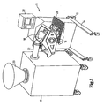
- Fig. 1 shows a view in perspective of an embodiment of a moulding device.
- the moulding device is denoted overall by reference numeral 10.
- the moulding device 10 comprises a frame 14 which can be displaced by means of castors 12.
- a moulding member 16 in this case a moulding drum which is arranged rotatably about a horizontal axis and which is, for example, driven by a drive means (not shown in more detail) such as an electric motor, is arranged on the frame 14.
- the moulding member 16 is provided with mould cavities which are not visible in Fig. 1 , in this case on the outer circumference of the moulding drum.
- a mass-distributing device 18 for distributing a mass to be moulded over the mould cavities of the moulding member 16 is in close contact therewith in a manner which is described in more detail below.
- a displaceable supply device 19 with introduction funnel 20 and a ((semi)continuously operating) pump (not illustrated) is connected to the mass-distributing device 18 by means of a detachable connecting tube 22.
- a conveyor 26 in this case an endless discharge belt, is arranged on which products released from the mould cavities are deposited and for example moved to the next processing station, such as an egg-white-coating device, a breading device, freezing device or packaging device.
- a control unit 28 is provided in order to control the various parts of the moulding device 10.
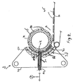
- Fig. 2 diagrammatically shows a cross section of an embodiment of a mass-distributing device 18.
- the mass-distributing device 18 comprises a housing 30 having an introduction opening 32 which is coupled to the mass supply device 19 via the connecting tube 22. From the introduction opening 32, a through-passage 34 extends through the housing 30 in a substantially radial direction of the moulding member 16, which passage 34 ends in or widens to a discharge 36 which extends across the width (axial direction) of the moulding member 16 on an open side 38 of the housing 30, in which a flexible abutment element 40 is provided to allow the distributing device 18 to abut the moulding member 16.
- the open side 38 of the housing 30 is virtually semicircular, in accordance with an arc section of the cylindrical periphery of the moulding member 16.
- the flexible abutment element 40 has a through-opening 42 which sealingly adjoins the discharge 36 of the through-passage 34.
- the moulding member 16 is provided with mould cavities 44 on the outer circumference of the cylindrical body. Mass is passed from the introduction opening 32 through the through-passage 34 and via the discharge 36 and the through-opening 42 in the flexible abutment element 40 into the mould cavities 44 which move past the through-opening 42 upon rotation of the moulding member 16. After being released from the mould cavities 44, moulded products 46 are placed on the conveyor 26 and transported away.
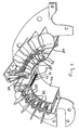
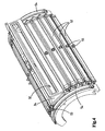
- pressure means 50 are provided near the open side 38 of the housing 30 for each of the zones of the flexible abutment element 40 to be described below.
- the pressure means 50 comprise - see in particular Fig. 4 - pressure elements 52 which can expand under fluid pressure, for example of pressurized air or pressurized liquid such as water, such as hoses which extend in the axial direction and are connected to a source of pressurized fluid (not shown).
- similar pressure elements 54 are provided along the semicircular outer edges of the housing and extend along these outer edges in the circumferential direction.
- the pressure elements 52 and 54 can be set for each zone or individually to a predetermined contact pressure which may be, and in practice also is, different for each zone.
- the pressure elements 52, 54 are connected via connecting couplings 55 to a source of pressurized fluid, such as pressurized air.
- a source of pressurized fluid such as pressurized air.
- chambers 56 which extend in the axial and radial direction are provided, in this case box profiles having a rectangular cross section, and make it possible to compensate for any deviations or unevenness of the drum circumference.
- the head-end walls of the housing are provided with openings extending in the radial direction for accommodating the head-end sides of said chambers 56, which are arranged therein so as to be displaceable in the radial direction.
- Fig. 3 shows that, in the illustrated embodiment of the flexible element 40, the through-opening 42 has vertical walls 43 which adjoin the through-passage 34 in the radial direction.
- Fig. 3 furthermore shows that the flexible abutment element 40 on the upstream end (assuming that the moulding member 16 rotates in an anti-clockwise direction) has an entry side 70 which slopes radially obliquely inwards in the direction of the first contact pressure zone and is V-shaped in the axial direction or width direction. Meat mass which has leaked at the front despite the pressure zones which are still to be described in detail, is still carried along by the rotating movement of the moulding member, and is forced to the centre under the entry side 70 as a result of the height reduction and the V-shape.
- This Fig. 3 also shows a levelling area 74 (see Fig.
- the following contact pressure zones can be distinguished from the entry side 70, as diagrammatically illustrated in Fig. 5 in projection.
- Adjacent to the entry side 70 there is a pre-filling zone 72 with pre-filling zone pressure means having sufficiently large dimensions to cover a mould cavity 44 or a row of mould cavities extending in the axial direction of the moulding member 16.
- Mass is poured into the flexible abutment element 40 in the mould cavities of the moulding member at a filling pressure determined by the mass supply member of the moulding device, such as a pump or screw, from the discharge 36 through the through-opening 42, also referred to as the filling zone.
- the levelling zone 74 is situated adjacent to the through-opening 42 and here the contact pressure is set to such a high level by means of levelling zone pressure means that tendons, fibres and the like are cut between this part of the flexible abutment element 40 and the moulding member 16.
- This zone 76 also has dimensions which are sufficiently large to cover a mould cavity in the circumferential direction.
- Zone Contact pressure Aim Entry side - Entraining leaked mass
- Pre-filling zone ⁇ P fill , e.g. P fill -1 bar
- Preventing leakage to entry surface Allowing trapped air to escape from the mould cavity Filling zone P fill , e.g. ⁇ 4 bar, in particular ⁇ 3 bar
- Filling mass into the mould cavity Levelling zone >> P fill e.g. 2* P fill Cutting tendons, fibres etc.
- Post-filling zone > P fill , e.g.
Landscapes
- Engineering & Computer Science (AREA)
- Life Sciences & Earth Sciences (AREA)
- Food Science & Technology (AREA)
- Wood Science & Technology (AREA)
- Zoology (AREA)
- Manufacturing & Machinery (AREA)
- Chemical & Material Sciences (AREA)
- Polymers & Plastics (AREA)
- Processing Of Meat And Fish (AREA)
- Formation And Processing Of Food Products (AREA)
- Meat, Egg Or Seafood Products (AREA)
Description
- The invention relates to a moulding device for distributing a mass of foodstuff starting materials suitable for consumption, in particular a meat mass, over one or more mould cavities of a moulding member for moulding three-dimensional products from said mass.
- A moulding device of this type is known, for example, from
WO 2004002229 . In order to cooperate with a cylindrical moulding roller as moulding member, the outer circumference of which is provided with one or more mould cavities, the known mass distributing device comprises a virtually semicircular housing comprising a through-passage extending in the radial direction and having an inlet for the mass from a supply device and pump and having a discharge for the mass to the mould cavities in the moulding roller. The side of the mass-distributing device facing the moulding roller comprises a curved plate made from a flexible material, inter alia in order to compensate for possible deviations in the radius of the moulding roller. This plate is provided with a passage for said discharge. During use, a pressure cushion which extends in the circumferential direction of the moulding roller, in other words in the longitudinal direction of the flexible plate, and which can be pressurized by means of a suitable pressure medium, pushes the flexible plate against the outer circumference of the moulding roller in a sealing manner. During use, mass is (semi)continuously fed to the mass-distributing device by means of a pump or another supply member, with in each case either one mould cavity or a row of mould cavities situated in the axial direction of the moulding roller and arranged substantially next to one another being filled during rotation of the moulding roller. With this known device, products can be moulded at high speeds. - Since it has now been found that during use of this known moulding device with mass-distributing device there is a risk of the final product showing a number of undesirable deviations, in particular a lip or appendage on in particular the outer circumference of the moulded product, and inclusions of air which may have an undesirable effect on the behaviour of the moulded product during subsequent processing steps, such as shrinking during frying, baking, etc.
-
US 3871085 discloses a moulding device for moulding three-dimensional products from a mass of foodstuff starting materials suitable for consumption, comprising a cylindrical moulding drum which is provided on the outer circumference thereof with open mould cavities. The mass-distributing device for supplying the mass to the mould cavities comprises a housing, which has a side turned towards the drum, which side is provided with a semicircular curved flexible abutment plate for abutting an arc section of the drum, The abutment plate comprises multiple different zones. A through-passage for the mass extends through the housing in a substantially radial direction of the drum from an introduction opening in the housing to a discharge extending across the width of the moulding drum, which discharge opens at the side of the housing turned towards the moulding drum. The moulding device comprises bolts supporting trunnions and trunnion bearings as well as a shoe operated by bolts to position the flexible abutment plate under pressure against the outer circumference of the drum. This allows to set a contact pressure in separate zones of the flexible abutment plate. - It is an object of the invention to provide an improved mass-distributing device, which does not suffer or suffers to a lesser degree from said shortcomings, or to provide a usable alternative.
- This object is achieved according to the invention by a moulding device according to claim 1.
- According to the invention, these pressure means are designed such that different zones of the flexible abutment plate can be pushed against the moulding drum at different contact pressures. This makes it possible, depending on the progress of the filling process, to set the contact pressures in the different zones during the filling process of the mould cavities of a moulding drum. As, with a moulding device with a continuous supply of mass at, usually, a substantially constant filling pressure, the mass-distributing device is often stationary with respect to a moulding member moving past this device; in particular an endless moulding member, such as a moulding roller or drum, each of the different pressures can be set to a desired value for the respective mass and mould cavities which value does not have to vary for the respective zone over time for a certain type of product, but may be constant and preferably is also constant. Due to the different pressures which are exerted by the different zones of the flexible abutment plate on the moulding member and the mass, which is and has been introduced into a mould cavity, it is possible to effectively prevent or reduce deviations from the desired shape, in particular inclusions of air during filling and producing lips on a moulded product.
- In a preferred embodiment, in particular for a meat mass, the pressure means are designed to separately setting contact pressures in a pre-filling zone and a post-filling zone of the flexible abutment plate. In other words, with this preferred embodiment, the pressure means comprise both pre-filling zone pressure means for setting the contact pressure in the pre-filling zone of the flexible abutment plate, and post-filling zone pressure means for setting the contact pressure in a post-filling zone of the flexible abutment plate. As has already been indicated above, the mass-distributing device is usually stationary with respect to a moulding member moving past this device. Said zones are linked to the relative movement - during the filling process - of the mass-distributing device and the mould cavity/cavities of the moulding member to be filled. The pre-filling zone is a section of the flexible abutment plate which is situated upstream from, advantageously directly adjoining, the filling area, viewed in the relative direction of movement of the moulding member with respect to the mass-distributing device. Likewise viewed in said direction of movement, the length of the pre-filling zone is advantageously at least equal to the largest dimension of a mould cavity in said direction. In this pre-filling zone, a mould cavity to be filled with mass is covered by the flexible abutment plate at a certain contact pressure in such a manner that leakage of mass in the upstream direction, in other words counter to the direction of movement, is prevented. This could occur if the downstream start of a mould cavity slides into the filling area and the mass, which is pressed into the mould cavity by means of the filling pressure of the supply member, moves through the mould cavity to the upstream end which is situated opposite the start or beyond that end due to the lower contact pressure (atmospheric or even lower with forced suction) compared to the filling pressure. Preferably, however, in addition to the prevention of leakage of mass, it is on the other hand possible for air to escape from the mould cavity. The contact pressure to be set in the pre-filling zone depends to a large degree on the starting material, the geometry of the through-passage and the mould cavity/cavities of the moulding member. Usually, the contact pressure in the pre-filling zone is in a range around the filling pressure, for example in a range of the filling pressure ± 1 atmosphere. This pre-filling zone pressure can readily be determined experimentally. If desired, the contact pressure in a pre-filling zone comprising several parts can be set in stages. In a further embodiment, the contact pressure in the pre-filling zone can be as low as 0 bar.
- In a similar manner, the post-filling zone is a section of the flexible abutment plate which, viewed in the described direction of movement, is situated downstream from the filling area. During use, the post-filling zone pressure means press this zone of the flexible abutment plate against the moulding member at a contact pressure which is higher than the filling pressure, so that leakage of mass in the direction of movement, is also prevented during filling, in other words to the downstream start of the mould cavity. Expediently, the length of the post-filling zone is at least equal to the largest dimension of a mould cavity, said length and largest dimension again being viewed in the direction of movement. In addition, this contact pressure, which is greater than the filling pressure, exerts a force on the mass filled into the mould cavity for some time after filling, which is advantageous for some types of mass, such as meat masses.
- In a further preferred embodiment, the pressure means are designed to separately set the contact pressure in at least one levelling zone, which adjoins the filling area in the downstream direction, of the flexible abutment plate. In the levelling zone, which is situated downstream of the filling area and upstream from the post-filling zone, a levelling means, such as a blade which advantageously forms an integral part of the flexible abutment element, such as an acute angle of said abutment element, is pressed against the moulding member at a contact pressure, which contact pressure is able to level off the mass in the mould cavity and to cut fibres, tendons, muscles, etc. which are present in the mass, such as for example in the case of a meat mass. In an alternative embodiment, the levelling means is arranged in a fixed position, independently of the filling pressure applied, at a contact pressure which may or may not be presettable. In this alternative embodiment, the contact pressure is not controlled dynamically.
- In a further preferred embodiment, the pressure means are designed to set the contact pressure in a relaxation zone of the flexible abutment plate, which zone adjoins the post-filling zone downstream. The relaxation zone is a zone which is situated downstream of the filling zone, where a mould cavity is again covered by the flexible abutment element at a contact pressure between the flexible abutment element and moulding member which allows gases, for example air, which are present in the mass with which the mould cavity is filled and which are compressed as a result of the filling operation, to expand. The contact pressure in the relaxation zone is therefore lower than the filling pressure. The relaxation zone is usually the last zone of the flexible abutment element which is passed by the mould cavity.
- According to a further preferred embodiment, the flexible abutment plate has an entry side - adjacent to the first zone, usually the pre-filling zone - which runs obliquely upwards counter to the direction of movement of the moulding member. If mass has nevertheless leaked in the upstream direction, this is carried along by the (relative) movement of the moulding member in between the flexible abutment element and the moulding member and is still forced into a mould cavity by the entry side which together with said moulding member forms a kind of funnel, as it were. To this end, the entry side is advantageously formed in the shape of a V the tip of which is turned away from the moulding member and which forces the entrained mass towards the centre.
- In this case, it is possible for each pressure element to be expandable under fluid pressure and to be connected to a source of pressure fluid which is under superatmospheric pressure, preferably a gas, for example pressurized air. Each pressure element comprises for example one or more connecting couplings for connecting the pressure elements to a source of pressurized fluid, such as pressurized air. The pressure elements each comprise, for example, a pressure cushion or hose or bellows. However, the pressure elements may be designed differently and, for example, comprise (pneumatic) cylinders. For example, one or more pressure elements may expand electrically rather than as a result of fluid pressure.
- In one embodiment, each pressure element comprises an elongate profiled section which extends in the transverse direction of the flexible abutment plate, and in which, in the mass-distributing device, several elongate profiled sections are arranged at a distance from one another on a side of the flexible abutment element which is designed to be turned away from the moulding member, and in which the member of each pressure element which can expand under fluid pressure engages with or, if desired, is connected to the elongate profiled-section of said pressure element in order to exert a pressure force on the flexible abutment element via the elongate profiled section. The elongate profiled sections can direct the contact pressures locally into the flexible abutment element, so that the contact pressures can be accurately set for each zone.
- In order to prevent leakage along the longitudinal edges, the pressure means are designed to set the contact pressure between the abutment element and the moulding member in one or both edge zones situated along the longitudinal edges of the flexible abutment element. Such longitudinal edge zone pressure means are advantageously pressure elements which extend in the longitudinal direction of the flexible abutment element and are expandable under fluid pressure, which pressure elements are situated on the longitudinal edges of the flexible abutment element and are each connected to a source of pressure fluid under superatmospheric pressure. The pressure means of the edge zones may be designed in accordance with the pressure elements of the other zones, as described above. In that case, however, the elongate pressure elements run in the longitudinal direction of the flexible abutment element and/or the moulding member, with a cylindrical moulding member running in the circumferential direction of said moulding member.
- It is possible for the pressure means to be provided with one or more pressure sensors in order to detect the current contact pressure in each zone of the flexible abutment plate. Each zone then preferably has at least one pressure sensor by means of which the contact pressure in said zone can be detected. The pressure sensors are, for example, connected to a control unit which receives the contact pressures detected by the pressure sensors. The control unit is designed to control the pressure elements in order to set the contact pressures in the different zones. By means of the pressure sensors and the control unit, it is possible to control the contact pressures accurately.
- For example, the control unit comprises a memory for storing one or more sets of desired pressure values for the pressure means. For example, it is provided that with a certain moulding member which comprises certain mould cavities, a set of pressure values for the pressure means is stored. These stored pressure values may, for example, be adapted to the dimensions of the mould cavities and/or the filling pressure which is used to fill these mould cavities with mass. For example, it is provided that the moulding member is automatically recognized so that the associated set of stored pressure values is automatically selected.
- For example, the control unit comprises an algorithm which controls the pressure value of one or more pressure means as a function of the set desired and/or current measured filling pressure of the mass.
- Advantageously, in addition to said pressure elements expandable under fluid pressure, the pressure means comprise one or more chambers which preferably extend parallel to the pressure elements, which chambers are arranged between the pressure elements and the flexible abutment plate in order to be able to readily compensate for unevenness of the moulding member, for example a non-constant radius of a moulding drum. On the outer circumference, the housing may be provided with reinforcement ribs or strips which extend in the axial and/or circumferential direction in order to impart the desired strength and rigidity to the structure.
- The invention also relates to a method according to claim 10 for operating a moulding device according to the invention, in which the contact pressure in one or more zones of the flexible abutment element is set in accordance with the following equations, in which Pfill is the filling pressure:
- pre-filling zone: P = Pfill, for example Pfill 1 atm < P < Pfill + 1 atm
- levelling zone: P> Pfill, preferably P >> Pfill
- post-filling zone: P > Pfill
- relaxation zone: P < Pfill, and/or
- edge zone: P > Pfill.
- It is possible for the abutment plate to comprise one or more plate parts.
- Furthermore, a measuring device may be provided for measuring the filling pressure, with the pressure means being coupled to said measuring device and being designed to influence the contract pressure in one or more zones of the flexible abutment plate. It is also possible for each zone to be associated with a pressure element which can expand under fluid pressure, and a pressure-measuring device for measuring the pressure in said pressure element. The pressure-measuring device may be connected to a control device comprising a display for set and/or measured pressures.
- The invention will be described below with reference to the attached drawing, in which:
-
Fig. 1 shows a diagrammatic perspective view of an embodiment of a moulding device; -
Fig. 2 shows a diagrammatic view of an embodiment of a mass-distributing device of a moulding device; -
Figs. 3 and4 show diagrammatic views of details of an embodiment of a mass-distributing device of a moulding device according to the invention; and -
Fig. 5 shows a diagrammatic view of different zones of the flexible abutment element. -
Fig. 1 shows a view in perspective of an embodiment of a moulding device. The moulding device is denoted overall byreference numeral 10. Themoulding device 10 comprises aframe 14 which can be displaced by means ofcastors 12. A mouldingmember 16, in this case a moulding drum which is arranged rotatably about a horizontal axis and which is, for example, driven by a drive means (not shown in more detail) such as an electric motor, is arranged on theframe 14. Themoulding member 16 is provided with mould cavities which are not visible inFig. 1 , in this case on the outer circumference of the moulding drum. A mass-distributingdevice 18 according to the invention for distributing a mass to be moulded over the mould cavities of themoulding member 16 is in close contact therewith in a manner which is described in more detail below. Adisplaceable supply device 19 withintroduction funnel 20 and a ((semi)continuously operating) pump (not illustrated) is connected to the mass-distributingdevice 18 by means of a detachable connectingtube 22. Below themoulding member 16 and the mass-distributingdevice 18, aconveyor 26, in this case an endless discharge belt, is arranged on which products released from the mould cavities are deposited and for example moved to the next processing station, such as an egg-white-coating device, a breading device, freezing device or packaging device. Acontrol unit 28 is provided in order to control the various parts of themoulding device 10. -
Fig. 2 diagrammatically shows a cross section of an embodiment of a mass-distributingdevice 18. The mass-distributingdevice 18 comprises a housing 30 having anintroduction opening 32 which is coupled to themass supply device 19 via the connectingtube 22. From the introduction opening 32, a through-passage 34 extends through the housing 30 in a substantially radial direction of themoulding member 16, whichpassage 34 ends in or widens to a discharge 36 which extends across the width (axial direction) of themoulding member 16 on anopen side 38 of the housing 30, in which aflexible abutment element 40 is provided to allow the distributingdevice 18 to abut themoulding member 16. Theopen side 38 of the housing 30 is virtually semicircular, in accordance with an arc section of the cylindrical periphery of themoulding member 16. Theflexible abutment element 40 has a through-opening 42 which sealingly adjoins the discharge 36 of the through-passage 34. Themoulding member 16 is provided with mould cavities 44 on the outer circumference of the cylindrical body. Mass is passed from the introduction opening 32 through the through-passage 34 and via the discharge 36 and the through-opening 42 in theflexible abutment element 40 into the mould cavities 44 which move past the through-opening 42 upon rotation of themoulding member 16. After being released from the mould cavities 44, moulded products 46 are placed on theconveyor 26 and transported away. - As can be seen more clearly in
Figs. 3 and4 , pressure means 50 are provided near theopen side 38 of the housing 30 for each of the zones of theflexible abutment element 40 to be described below. The pressure means 50 comprise - see in particularFig. 4 -pressure elements 52 which can expand under fluid pressure, for example of pressurized air or pressurized liquid such as water, such as hoses which extend in the axial direction and are connected to a source of pressurized fluid (not shown). Furthermore,similar pressure elements 54 are provided along the semicircular outer edges of the housing and extend along these outer edges in the circumferential direction. Thepressure elements pressure elements couplings 55 to a source of pressurized fluid, such as pressurized air. Between thepressure elements flexible abutment element 40,chambers 56 which extend in the axial and radial direction are provided, in this case box profiles having a rectangular cross section, and make it possible to compensate for any deviations or unevenness of the drum circumference. To this end, the head-end walls of the housing are provided with openings extending in the radial direction for accommodating the head-end sides of saidchambers 56, which are arranged therein so as to be displaceable in the radial direction.Fig. 3 shows that, in the illustrated embodiment of theflexible element 40, the through-opening 42 has vertical walls 43 which adjoin the through-passage 34 in the radial direction. -
Fig. 3 furthermore shows that theflexible abutment element 40 on the upstream end (assuming that themoulding member 16 rotates in an anti-clockwise direction) has anentry side 70 which slopes radially obliquely inwards in the direction of the first contact pressure zone and is V-shaped in the axial direction or width direction. Meat mass which has leaked at the front despite the pressure zones which are still to be described in detail, is still carried along by the rotating movement of the moulding member, and is forced to the centre under theentry side 70 as a result of the height reduction and the V-shape. ThisFig. 3 also shows a levelling area 74 (seeFig. 5 ) in the shape of a blade, formed by an acute angle between the main surface area of theabutment element 40 and the vertical wall 43, which delimits the through-opening 42 on the downstream side (relative to the direction of movement of the moulding member 16). - In the illustrated embodiment, the following contact pressure zones can be distinguished from the
entry side 70, as diagrammatically illustrated inFig. 5 in projection. Adjacent to theentry side 70, there is apre-filling zone 72 with pre-filling zone pressure means having sufficiently large dimensions to cover a mould cavity 44 or a row of mould cavities extending in the axial direction of themoulding member 16. Mass is poured into theflexible abutment element 40 in the mould cavities of the moulding member at a filling pressure determined by the mass supply member of the moulding device, such as a pump or screw, from the discharge 36 through the through-opening 42, also referred to as the filling zone. The levellingzone 74 is situated adjacent to the through-opening 42 and here the contact pressure is set to such a high level by means of levelling zone pressure means that tendons, fibres and the like are cut between this part of theflexible abutment element 40 and themoulding member 16. Adjoining this levellingzone 74, there is apost-filling zone 76 with associated post-filling zone pressure means which are subjected to a higher contact pressure than the filling pressure and this prevents a mass poured into a mould cavity from being able to flow backwards (downstream). Thiszone 76 also has dimensions which are sufficiently large to cover a mould cavity in the circumferential direction. In an adjoiningrelaxation zone 78, the contact pressure is set lower than the filling pressure by means of relaxation zone pressure means, as a result of which gases trapped in the moulded mass can expand.Edge zones 80 are defined along the longitudinal edges and can be pressurized with the aid of the edge zone pressure means 54. - The following table shows the contact pressure relative to the filling pressure (Pfill) for each of the zones.
Zone Contact pressure Aim Entry side - Entraining leaked mass Pre-filling zone ≈Pfill, e.g. Pfill-1 bar < Pre-fill < Pfill + 1 bar Preventing leakage to entry surface Allowing trapped air to escape from the mould cavity Filling zone Pfill, e.g. < 4 bar, in particular < 3 bar Filling mass into the mould cavity Levelling zone >> Pfill e.g. 2* Pfill Cutting tendons, fibres etc. Post-filling zone > Pfill, e.g. Pfill + 1 bar Preventing leakage to relaxation zone and ensuring flexible abutment element presses onto moulding member Relaxation zone < Pfill, e.g. Pfill - 1 bar Allowing gas bubbles trapped in the mass to expand Edge zone > Pfill, e.g. Pfill + 1 bar Preventing leakage to lateral edges - As is shown in
Fig. 2 , in this exemplary embodiment, viewed in the circumferential direction the length of the mould cavities 44 of themoulding member 16 is greater than the height of the discharge 36. As the mould cavity 44 passes the discharge 36, a portion of the mould cavity 44 extends beyond the discharge 36. A portion of the mould cavity 44 which is connected to the discharge 36 is situated downstream of the discharge 36, that is to say at the location of the levellingzone 74 and/or thepost-filling zone 76. It is possible to set the pressure in the levellingzone 74 and/or thepost-filling zone 76, if desired temporarily, to be smaller than or equal to the filling pressure (Pfill). As a result thereof, theflexible abutment element 40 can move slightly away from the mouldingmember 16 directly downstream of the discharge 36, that is to say at the location of the levellingzone 74 and/or thepost-filling zone 76, so that more meat mass can be passed to the mould cavity 44 of themoulding member 16 associated with the discharge 36. As a result thereof, the shaped weight of the moulded product in the mould cavity 44 increases. - The invention is not limited to the above-described embodiments. Those skilled in the art may be able to think of various modifications which are within the scope of the invention. Thus, it is for example possible to measure the weight of the moulded product, optionally automatically, with the contact pressures in the levelling zone and/or the post-filling zone and/or relaxation zone being set on the basis of the measured weight.
Claims (11)
- Moulding device (10) for moulding three-dimensional products from a mass of foodstuff starting materials suitable for consumption, in particular a meat mass, comprising:• a cylindrical moulding drum (16) which is rotatable in a rotation direction along a movement path by associated drive means and which is provided on the outer circumference (35) thereof with open mould cavities (44), the moulding drum having a width in axial direction,• a supply member for supplying said mass to a mass-distributing device (18),• a mass-distributing device (18) for supplying the mass to one or more mould cavities (44) of the moulding drum (16), the mass-distributing device being arranged at a mass-supply position along the movement path of the moulding drum (16) for distributing the mass over the one or more mould cavities (44), the mass-distributing device comprising:∘ a housing (30), which has a side (38) turned towards the moulding drum (16), which side (38) is provided with a semicircular curved flexible abutment plate (40) for abutting an arc section of the moulding drum (16), the abutment plate having a width extending in the direction of, and essentially corresponding to the width of the moulding drum, a curvature - viewed in the axial direction of the moulding drum - corresponding to the outer circumference of the moulding drum, a length perpendicular to its width, viewed in the rotational direction of the moulding drum, and longitudinal edges, and wherein the abutment plate comprises multiple different zones;∘ a through-passage (34) for said mass extending through the housing (30) in a substantially radial direction of the moulding drum (16) from an introduction opening (32) in the housing (30) to a discharge (36) extending across the width of the moulding drum (16), which discharge (36) opens at the side (38) of the housing (30) turned towards the moulding drum (16), in which the discharge (36) and the moulding drum (16) are movable relative to one another in a relative direction of movement,∘ pressure means (50) to position the flexible abutment plate (40) under pressure against the outer circumference (35) of the moulding drum (16) comprising the one or more mould cavities (44), wherein the pressure means (50) comprise at least one pressure element to set a contact pressure in each of the multiple separate zones (72, 74, 76, 78) of the flexible abutment plate (40),▪ wherein elongated pressure elements (52) are provided which extend in the direction of the width, transverse to the longitudinal direction, of the flexible abutment plate to set a contact pressure in zones extending in the axial direction of the flexible abutment plate,▪ wherein edge zone pressure elements (54) are provided along the semicircular outer edges of the flexible abutment plate and extend along these outer edges in the circumferential direction to set a contact pressure in one or more edge zones (80) situated along the longitudinal edges of the flexible abutment plate (40) independently of the setting of a contact pressure in at least one of the other zones (72, 74, 76, 78) of the flexible abutment plate (40).
- Moulding device according to claim 1, in which the flexible abutment plate (40) comprises a pre-filling zone (72) which is defined by a section of the flexible abutment plate (40) which, viewed in the relative direction of movement of the moulding drum (16) with respect to the discharge (36), is situated upstream of the discharge (36), and in which the pressure means (50) are designed to separately set the contact pressure in the pre-filling zone (72) of the flexible abutment plate (40).
- Moulding device according to claim 1 or 2, in which the flexible abutment plate (40) comprises a post-filling zone (76) which is defined by a section of the flexible abutment plate (40) which, viewed in the relative direction of movement of the moulding member (16) with respect to the discharge (36), is situated downstream of the discharge (36), and in which the pressure means (50) are designed to separately set the contact pressure in the post-filling zone (76) of the flexible abutment plate (40).
- Moulding device according to one or more of the preceding claims, in which the flexible abutment plate (40) comprises a levelling zone (74) which is defined by a section of the flexible abutment plate (40) which, viewed in the relative direction of movement of the moulding drum (16) with respect to the discharge (36), is situated downstream of and adjoining the discharge (36), and in which the pressure means (50) are designed to separately set the contact pressure in at least the levelling zone (74).
- Moulding device according to claim 3 or 4, in which the flexible abutment plate (40) comprises a relaxation zone (78) which is defined by a section of the flexible abutment plate (40) which, viewed in the relative direction of movement of the moulding drum (16) with respect to the discharge (36), is situated downstream of and adjoining the post-filling zone (76), and in which the pressure means (50) are designed to set the contact pressure in the relaxation zone (78).
- Moulding device according to one or more of the preceding claims, in which the flexible abutment plate (40) has an entry side (70) which runs from a first zone, in particular the pre-filling zone (72), obliquely away from the side (38) of the housing (30) which can be turned towards the moulding drum (16), in which the entry side (70) is, for example, substantially V-shaped in cross section.
- Moulding device according to one of the preceding claims, in which each pressure element (52) comprises a member which can expand under fluid pressure and which can be connected to a source of pressure fluid under superatmospheric pressure.
- Moulding device according to claim 7, in which each pressure element (52) comprises an elongate profiled section (56) which extends in a transverse direction of the flexible abutment plate (40), and in which the elongate profiled sections (56) are arranged at a distance from one another on a side of the flexible abutment plate (40) which can be turned away from the moulding drum (16), and in which the member of each pressure element (52) which can expand under fluid pressure engages with the elongate profiled section (56) of said pressure element (52) in order to exert a pressure force on the flexible abutment plate (40) via the elongate profiled section (56).
- Moulding device according to one of the preceding claims, in which the pressure means (50) are provided with pressure sensors for detecting the contact pressure in each zone (72,74,76,78) of the flexible abutment plate (40).
- Method for operating a moulding device (18) according to one of claims 1-9, in which the contact pressure between one or more zones of the flexible abutment plate (40) and the moulding drum (16) is set in accordance with the following equations, in which Pfill is the filling pressure at which the mass is passed from the discharge (36) into the moulding cavities (44) of the moulding drum (16):levelling zone: P> Pfill, preferably P >>Pfill,post-filling zone: P > Pfill,relaxation zone: P < Pfill, and/oredge zone: P > Pfill.
- Method according to claim 10, in which.the contact pressure in a pre-filling zone is set to a value in the range between Pfill - 1 bar and Pfill + 1 bar.
Applications Claiming Priority (2)
| Application Number | Priority Date | Filing Date | Title |
|---|---|---|---|
| NL2002672A NL2002672C2 (en) | 2009-03-26 | 2009-03-26 | MASS DIVIDING DEVICE AND MOLDING DEVICE CONTAINING SUCH A MASS DIVIDING DEVICE. |
| PCT/NL2010/000058 WO2010110655A1 (en) | 2009-03-26 | 2010-03-26 | Mass-distributing device and moulding device comprising a mass- distributing device of this type. |
Publications (3)
| Publication Number | Publication Date |
|---|---|
| EP2410864A1 EP2410864A1 (en) | 2012-02-01 |
| EP2410864B1 EP2410864B1 (en) | 2013-02-13 |
| EP2410864B2 true EP2410864B2 (en) | 2016-09-28 |
Family
ID=41258639
Family Applications (1)
| Application Number | Title | Priority Date | Filing Date |
|---|---|---|---|
| EP10712178.2A Active EP2410864B2 (en) | 2009-03-26 | 2010-03-26 | Moulding device comprising a mass- distributing device |
Country Status (7)
| Country | Link |
|---|---|
| US (2) | US9044029B2 (en) |
| EP (1) | EP2410864B2 (en) |
| CN (2) | CN105165997B (en) |
| BR (1) | BRPI1014200B1 (en) |
| DK (1) | DK2410864T4 (en) |
| NL (1) | NL2002672C2 (en) |
| WO (1) | WO2010110655A1 (en) |
Families Citing this family (25)
| Publication number | Priority date | Publication date | Assignee | Title |
|---|---|---|---|---|
| ES2484843T3 (en) | 2008-07-04 | 2014-08-12 | Cfs Bakel B.V. | Apparatus and process of formation of food products |
| NL2003185C2 (en) * | 2009-07-10 | 2011-01-11 | Stork Titan Bv | Moulding device, moulding element, moulding method, food preparation method and moulded product. |
| EP2449893B1 (en) | 2010-11-04 | 2016-08-17 | GEA Food Solutions Bakel B.V. | Mass distribution device and molding device |
| PL2468104T3 (en) | 2010-12-23 | 2019-02-28 | Gea Food Solutions Bakel B.V. | Cleaning method for a mould drum |
| ES2541841T3 (en) | 2011-01-25 | 2015-07-27 | Gea Food Solutions Bakel B.V. | Food production chain |
| US9730467B2 (en) | 2011-02-10 | 2017-08-15 | Gea Food Solutions Bakel B.V. | Food forming drum |
| NL2006841C2 (en) | 2011-05-24 | 2012-11-27 | Marel Townsend Further Proc Bv | FORMATION DEVICE, AND METHOD FOR FORMING A FOOD PRODUCT. |
| CA2841854C (en) * | 2011-07-25 | 2017-08-22 | Gea Food Solutions Bakel B.V. | Food forming apparatus with a food feed member |
| RU2656384C1 (en) | 2012-01-20 | 2018-06-05 | Геа Фуд Сольюшнс Бакел Б.В. | System for feeding mass |
| WO2013115647A1 (en) | 2012-02-03 | 2013-08-08 | Marel Townsend Further Processing B.V. | Moulding food products from a pumpable foodstuff mass |
| CN104540387B (en) * | 2012-07-27 | 2017-06-23 | 马雷尔汤森深加工公司 | A kind of method and apparatus for moulding food pie from food article |
| ES2892334T3 (en) | 2013-02-01 | 2022-02-03 | Gea Food Solutions Bakel Bv | Food Forming Drum |
| NL2010482C2 (en) * | 2013-03-19 | 2014-09-24 | Marel Townsend Further Proc Bv | FORMATION DEVICE AND METHOD FOR FORMING FOOD PRODUCTS. |
| JP6393313B2 (en) | 2013-05-03 | 2018-09-19 | ジーイーエイ・フード・ソリューションズ・バーケル・ベスローテン・フェンノートシャップ | Sealing member for food forming drum |
| EP4252537A1 (en) * | 2013-12-02 | 2023-10-04 | GEA Food Solutions Bakel B.V. | Methods for filling cavities in a mould member |
| EP3076795A1 (en) * | 2013-12-04 | 2016-10-12 | GEA Food Solutions Bakel B.V. | Feed channel with a customized exit |
| RU2718000C2 (en) | 2015-03-13 | 2020-03-27 | Геа Фуд Сольюшнс Бакел Б.В. | Method for cleaning and storage of molding drum |
| US10395296B2 (en) * | 2016-01-29 | 2019-08-27 | Walmart Apollo, Llc | Database mining techniques for generating customer-specific maps in retail applications |
| US10492502B2 (en) * | 2016-05-10 | 2019-12-03 | Tomahawk Manufacturing | Paper interleaver |
| NL2016928B1 (en) | 2016-06-09 | 2018-01-24 | Marel Townsend Further Proc Bv | Moulding device and method for moulding |
| NL2018036B1 (en) * | 2016-12-21 | 2018-06-28 | Marel Townsend Further Proc Bv | Installations and methods for moulding food products with a pressurized air food product ejection system from a mould drum |
| CA3056401A1 (en) | 2017-04-19 | 2018-10-25 | Gea Food Solutions Bakel B.V. | Improved de-aeration cavities in a mould member |
| NL2024251B1 (en) | 2019-11-18 | 2021-07-21 | Marel Further Proc Bv | Food process line for in-line processing food and method for processing food |
| NL2027519B1 (en) | 2021-02-08 | 2022-09-09 | Marel Further Proc Bv | A food processing line and method for controlling a food processing line |
| RU210069U1 (en) * | 2021-08-23 | 2022-03-28 | Общество с ограниченной ответственностью "Внедренческое конструкторское предприятие "Сигнал-Пак" | MEAT FEEDER FOR Dumplings Machine |
Citations (6)
| Publication number | Priority date | Publication date | Assignee | Title |
|---|---|---|---|---|
| US3446404A (en) † | 1967-06-20 | 1969-05-27 | Maharaj K Mehta | Encapsulation of powders |
| US4792457A (en) † | 1986-12-19 | 1988-12-20 | Kraft, Inc. | Method for manufacturing individually wrapped meat slices |
| EP0818148A1 (en) † | 1996-07-11 | 1998-01-14 | Koppens B.V. | Moulding system for moulding a mass, such as a mass of meat |
| DE69516640T2 (en) † | 1994-12-05 | 2000-12-28 | Barilla Alimentare S.P.A., Parma | Process and device for the manufacture of cereal aggregates on an industrial basis |
| EP1262111A1 (en) † | 2001-05-31 | 2002-12-04 | Meincke A/S | An apparatus for pressing granular food material |
| US20020182297A1 (en) † | 2000-04-28 | 2002-12-05 | Golden State Foods Corp. | Food patty molding apparatus |
Family Cites Families (19)
| Publication number | Priority date | Publication date | Assignee | Title |
|---|---|---|---|---|
| US3137029A (en) * | 1960-12-20 | 1964-06-16 | Zolt Fern A De | Ground meat patty forming machine |
| BE790198A (en) * | 1971-10-27 | 1973-02-15 | Aquarius C | DEVICE FOR MANUFACTURING LOLLIES |
| SU891053A1 (en) * | 1980-04-28 | 1981-12-23 | Кемеровский технологический институт пищевой промышленности | Device for moulding candy mass |
| US4460611A (en) * | 1981-08-20 | 1984-07-17 | Kisaku Suzuki | Method of shaping food |
| US4506184A (en) * | 1984-01-10 | 1985-03-19 | Varian Associates, Inc. | Deformable chuck driven by piezoelectric means |
| US4957425A (en) * | 1989-05-15 | 1990-09-18 | Fay Rudolph J | Apparatus for producing shaped products |
| JPH06244269A (en) * | 1992-09-07 | 1994-09-02 | Mitsubishi Electric Corp | Semiconductor manufacturing apparatus, wafer vacuum chuck device thereof, and gas cleaning and nitride film formation therefor |
| DE19539359A1 (en) * | 1995-10-23 | 1997-04-24 | Knoll Ag | Forming calender |
| US5923408A (en) * | 1996-01-31 | 1999-07-13 | Canon Kabushiki Kaisha | Substrate holding system and exposure apparatus using the same |
| US6326046B1 (en) * | 1998-06-19 | 2001-12-04 | Tip Top Ice Cream Company Limited | Procedures for forming an extruded frozen novelty with high inclusions from a mouldable material |
| NL1010630C2 (en) * | 1998-11-23 | 2000-05-24 | Stork Pmt | To shape. |
| EP1077393A2 (en) * | 1999-08-19 | 2001-02-21 | Canon Kabushiki Kaisha | Substrate attracting and holding system for use in exposure apparatus |
| US7018572B2 (en) * | 2001-06-11 | 2006-03-28 | General Electric Company | Method for producing data storage media |
| NL1020942C2 (en) * | 2002-06-26 | 2003-12-30 | Stork Titan Bv | Forming device. |
| US7641840B2 (en) * | 2002-11-13 | 2010-01-05 | Molecular Imprints, Inc. | Method for expelling gas positioned between a substrate and a mold |
| NL1026171C2 (en) * | 2004-05-11 | 2005-11-14 | Stork Titan Bv | To shape. |
| US8215946B2 (en) * | 2006-05-18 | 2012-07-10 | Molecular Imprints, Inc. | Imprint lithography system and method |
| US7931461B2 (en) * | 2007-11-28 | 2011-04-26 | Stork Titan B.V. | Mould member for moulding three-dimensional products, system and methods of manufacturing a mould member |
| US8029266B2 (en) * | 2007-11-28 | 2011-10-04 | Stork Titan B.V. | Mould member for moulding three-dimensional products, system and methods of manufacturing a mould member |
-
2009
- 2009-03-26 NL NL2002672A patent/NL2002672C2/en active
-
2010
- 2010-03-26 WO PCT/NL2010/000058 patent/WO2010110655A1/en active Application Filing
- 2010-03-26 CN CN201510418688.XA patent/CN105165997B/en active Active
- 2010-03-26 CN CN201080020521.3A patent/CN102421298B/en active Active
- 2010-03-26 DK DK10712178.2T patent/DK2410864T4/en active
- 2010-03-26 US US13/259,923 patent/US9044029B2/en active Active
- 2010-03-26 BR BRPI1014200-2A patent/BRPI1014200B1/en active IP Right Grant
- 2010-03-26 EP EP10712178.2A patent/EP2410864B2/en active Active
-
2015
- 2015-05-27 US US14/723,069 patent/US9433238B2/en active Active
Patent Citations (6)
| Publication number | Priority date | Publication date | Assignee | Title |
|---|---|---|---|---|
| US3446404A (en) † | 1967-06-20 | 1969-05-27 | Maharaj K Mehta | Encapsulation of powders |
| US4792457A (en) † | 1986-12-19 | 1988-12-20 | Kraft, Inc. | Method for manufacturing individually wrapped meat slices |
| DE69516640T2 (en) † | 1994-12-05 | 2000-12-28 | Barilla Alimentare S.P.A., Parma | Process and device for the manufacture of cereal aggregates on an industrial basis |
| EP0818148A1 (en) † | 1996-07-11 | 1998-01-14 | Koppens B.V. | Moulding system for moulding a mass, such as a mass of meat |
| US20020182297A1 (en) † | 2000-04-28 | 2002-12-05 | Golden State Foods Corp. | Food patty molding apparatus |
| EP1262111A1 (en) † | 2001-05-31 | 2002-12-04 | Meincke A/S | An apparatus for pressing granular food material |
Also Published As
| Publication number | Publication date |
|---|---|
| US20150250226A1 (en) | 2015-09-10 |
| BRPI1014200A8 (en) | 2017-07-11 |
| CN102421298A (en) | 2012-04-18 |
| BRPI1014200A2 (en) | 2015-08-25 |
| US9433238B2 (en) | 2016-09-06 |
| WO2010110655A8 (en) | 2010-12-09 |
| EP2410864B1 (en) | 2013-02-13 |
| CN105165997A (en) | 2015-12-23 |
| US9044029B2 (en) | 2015-06-02 |
| CN105165997B (en) | 2018-01-12 |
| BRPI1014200B1 (en) | 2018-04-03 |
| CN102421298B (en) | 2015-07-29 |
| EP2410864A1 (en) | 2012-02-01 |
| WO2010110655A1 (en) | 2010-09-30 |
| US20120015065A1 (en) | 2012-01-19 |
| DK2410864T3 (en) | 2013-03-04 |
| NL2002672C2 (en) | 2010-09-28 |
| DK2410864T4 (en) | 2017-01-09 |
Similar Documents
| Publication | Publication Date | Title |
|---|---|---|
| EP2410864B2 (en) | Moulding device comprising a mass- distributing device | |
| RU2603925C2 (en) | Molding device for forming food products containing feeder for supply of food mass | |
| US11166470B2 (en) | Mass supply system | |
| JP5823607B2 (en) | Molding machine and method for molding food products | |
| JP2011078423A (en) | Mass feeding member | |
| DK2975944T3 (en) | CASTING EQUIPMENT AND PROCEDURE FOR CASTING FOOD | |
| RU2697271C1 (en) | Device and method of package degassing | |
| US20100037904A1 (en) | Dosing machine for controlled dosage of pasty products | |
| RU2655814C2 (en) | Sealing member for a food forming drum | |
| WO2019229038A2 (en) | Mould member with foreign object detection |
Legal Events
| Date | Code | Title | Description |
|---|---|---|---|
| PUAI | Public reference made under article 153(3) epc to a published international application that has entered the european phase |
Free format text: ORIGINAL CODE: 0009012 |
|
| 17P | Request for examination filed |
Effective date: 20111018 |
|
| AK | Designated contracting states |
Kind code of ref document: A1 Designated state(s): AT BE BG CH CY CZ DE DK EE ES FI FR GB GR HR HU IE IS IT LI LT LU LV MC MK MT NL NO PL PT RO SE SI SK SM TR |
|
| REG | Reference to a national code |
Ref country code: DE Ref legal event code: R079 Ref document number: 602010005010 Country of ref document: DE Free format text: PREVIOUS MAIN CLASS: A22C0007000000 Ipc: A21C0005000000 |
|
| DAX | Request for extension of the european patent (deleted) | ||
| RIC1 | Information provided on ipc code assigned before grant |
Ipc: A22C 7/00 20060101ALI20120621BHEP Ipc: A23P 1/10 20060101ALI20120621BHEP Ipc: A21C 5/00 20060101AFI20120621BHEP |
|
| GRAP | Despatch of communication of intention to grant a patent |
Free format text: ORIGINAL CODE: EPIDOSNIGR1 |
|
| GRAS | Grant fee paid |
Free format text: ORIGINAL CODE: EPIDOSNIGR3 |
|
| GRAA | (expected) grant |
Free format text: ORIGINAL CODE: 0009210 |
|
| AK | Designated contracting states |
Kind code of ref document: B1 Designated state(s): AT BE BG CH CY CZ DE DK EE ES FI FR GB GR HR HU IE IS IT LI LT LU LV MC MK MT NL NO PL PT RO SE SI SK SM TR |
|
| REG | Reference to a national code |
Ref country code: GB Ref legal event code: FG4D |
|
| REG | Reference to a national code |
Ref country code: AT Ref legal event code: REF Ref document number: 595978 Country of ref document: AT Kind code of ref document: T Effective date: 20130215 |
|
| REG | Reference to a national code |
Ref country code: DK Ref legal event code: T3 |
|
| REG | Reference to a national code |
Ref country code: IE Ref legal event code: FG4D |
|
| REG | Reference to a national code |
Ref country code: SE Ref legal event code: TRGR |
|
| REG | Reference to a national code |
Ref country code: NL Ref legal event code: T3 |
|
| REG | Reference to a national code |
Ref country code: DE Ref legal event code: R096 Ref document number: 602010005010 Country of ref document: DE Effective date: 20130411 |
|
| REG | Reference to a national code |
Ref country code: AT Ref legal event code: MK05 Ref document number: 595978 Country of ref document: AT Kind code of ref document: T Effective date: 20130213 |
|
| REG | Reference to a national code |
Ref country code: LT Ref legal event code: MG4D |
|
| PG25 | Lapsed in a contracting state [announced via postgrant information from national office to epo] |
Ref country code: IS Free format text: LAPSE BECAUSE OF FAILURE TO SUBMIT A TRANSLATION OF THE DESCRIPTION OR TO PAY THE FEE WITHIN THE PRESCRIBED TIME-LIMIT Effective date: 20130613 Ref country code: AT Free format text: LAPSE BECAUSE OF FAILURE TO SUBMIT A TRANSLATION OF THE DESCRIPTION OR TO PAY THE FEE WITHIN THE PRESCRIBED TIME-LIMIT Effective date: 20130213 Ref country code: LT Free format text: LAPSE BECAUSE OF FAILURE TO SUBMIT A TRANSLATION OF THE DESCRIPTION OR TO PAY THE FEE WITHIN THE PRESCRIBED TIME-LIMIT Effective date: 20130213 Ref country code: NO Free format text: LAPSE BECAUSE OF FAILURE TO SUBMIT A TRANSLATION OF THE DESCRIPTION OR TO PAY THE FEE WITHIN THE PRESCRIBED TIME-LIMIT Effective date: 20130513 Ref country code: ES Free format text: LAPSE BECAUSE OF FAILURE TO SUBMIT A TRANSLATION OF THE DESCRIPTION OR TO PAY THE FEE WITHIN THE PRESCRIBED TIME-LIMIT Effective date: 20130524 Ref country code: BG Free format text: LAPSE BECAUSE OF FAILURE TO SUBMIT A TRANSLATION OF THE DESCRIPTION OR TO PAY THE FEE WITHIN THE PRESCRIBED TIME-LIMIT Effective date: 20130513 |
|
| PG25 | Lapsed in a contracting state [announced via postgrant information from national office to epo] |
Ref country code: SI Free format text: LAPSE BECAUSE OF FAILURE TO SUBMIT A TRANSLATION OF THE DESCRIPTION OR TO PAY THE FEE WITHIN THE PRESCRIBED TIME-LIMIT Effective date: 20130213 Ref country code: FI Free format text: LAPSE BECAUSE OF FAILURE TO SUBMIT A TRANSLATION OF THE DESCRIPTION OR TO PAY THE FEE WITHIN THE PRESCRIBED TIME-LIMIT Effective date: 20130213 Ref country code: PL Free format text: LAPSE BECAUSE OF FAILURE TO SUBMIT A TRANSLATION OF THE DESCRIPTION OR TO PAY THE FEE WITHIN THE PRESCRIBED TIME-LIMIT Effective date: 20130213 Ref country code: PT Free format text: LAPSE BECAUSE OF FAILURE TO SUBMIT A TRANSLATION OF THE DESCRIPTION OR TO PAY THE FEE WITHIN THE PRESCRIBED TIME-LIMIT Effective date: 20130613 Ref country code: BE Free format text: LAPSE BECAUSE OF FAILURE TO SUBMIT A TRANSLATION OF THE DESCRIPTION OR TO PAY THE FEE WITHIN THE PRESCRIBED TIME-LIMIT Effective date: 20130213 Ref country code: LV Free format text: LAPSE BECAUSE OF FAILURE TO SUBMIT A TRANSLATION OF THE DESCRIPTION OR TO PAY THE FEE WITHIN THE PRESCRIBED TIME-LIMIT Effective date: 20130213 Ref country code: GR Free format text: LAPSE BECAUSE OF FAILURE TO SUBMIT A TRANSLATION OF THE DESCRIPTION OR TO PAY THE FEE WITHIN THE PRESCRIBED TIME-LIMIT Effective date: 20130514 |
|
| PG25 | Lapsed in a contracting state [announced via postgrant information from national office to epo] |
Ref country code: HR Free format text: LAPSE BECAUSE OF FAILURE TO SUBMIT A TRANSLATION OF THE DESCRIPTION OR TO PAY THE FEE WITHIN THE PRESCRIBED TIME-LIMIT Effective date: 20130213 |
|
| PG25 | Lapsed in a contracting state [announced via postgrant information from national office to epo] |
Ref country code: SK Free format text: LAPSE BECAUSE OF FAILURE TO SUBMIT A TRANSLATION OF THE DESCRIPTION OR TO PAY THE FEE WITHIN THE PRESCRIBED TIME-LIMIT Effective date: 20130213 Ref country code: EE Free format text: LAPSE BECAUSE OF FAILURE TO SUBMIT A TRANSLATION OF THE DESCRIPTION OR TO PAY THE FEE WITHIN THE PRESCRIBED TIME-LIMIT Effective date: 20130213 Ref country code: MC Free format text: LAPSE BECAUSE OF NON-PAYMENT OF DUE FEES Effective date: 20130331 Ref country code: RO Free format text: LAPSE BECAUSE OF FAILURE TO SUBMIT A TRANSLATION OF THE DESCRIPTION OR TO PAY THE FEE WITHIN THE PRESCRIBED TIME-LIMIT Effective date: 20130213 Ref country code: CZ Free format text: LAPSE BECAUSE OF FAILURE TO SUBMIT A TRANSLATION OF THE DESCRIPTION OR TO PAY THE FEE WITHIN THE PRESCRIBED TIME-LIMIT Effective date: 20130213 |
|
| PLBI | Opposition filed |
Free format text: ORIGINAL CODE: 0009260 |
|
| 26 | Opposition filed |
Opponent name: GEA FOOD SOLUTIONS BAKEL B.V. Effective date: 20131113 |
|
| PLAX | Notice of opposition and request to file observation + time limit sent |
Free format text: ORIGINAL CODE: EPIDOSNOBS2 |
|
| PG25 | Lapsed in a contracting state [announced via postgrant information from national office to epo] |
Ref country code: IT Free format text: LAPSE BECAUSE OF FAILURE TO SUBMIT A TRANSLATION OF THE DESCRIPTION OR TO PAY THE FEE WITHIN THE PRESCRIBED TIME-LIMIT Effective date: 20130213 |
|
| REG | Reference to a national code |
Ref country code: IE Ref legal event code: MM4A |
|
| PG25 | Lapsed in a contracting state [announced via postgrant information from national office to epo] |
Ref country code: IE Free format text: LAPSE BECAUSE OF NON-PAYMENT OF DUE FEES Effective date: 20130326 |
|
| REG | Reference to a national code |
Ref country code: DE Ref legal event code: R026 Ref document number: 602010005010 Country of ref document: DE Effective date: 20131113 |
|
| PLAF | Information modified related to communication of a notice of opposition and request to file observations + time limit |
Free format text: ORIGINAL CODE: EPIDOSCOBS2 |
|
| PLBB | Reply of patent proprietor to notice(s) of opposition received |
Free format text: ORIGINAL CODE: EPIDOSNOBS3 |
|
| PG25 | Lapsed in a contracting state [announced via postgrant information from national office to epo] |
Ref country code: MT Free format text: LAPSE BECAUSE OF FAILURE TO SUBMIT A TRANSLATION OF THE DESCRIPTION OR TO PAY THE FEE WITHIN THE PRESCRIBED TIME-LIMIT Effective date: 20130213 |
|
| REG | Reference to a national code |
Ref country code: CH Ref legal event code: PL |
|
| PG25 | Lapsed in a contracting state [announced via postgrant information from national office to epo] |
Ref country code: LI Free format text: LAPSE BECAUSE OF NON-PAYMENT OF DUE FEES Effective date: 20140331 Ref country code: CH Free format text: LAPSE BECAUSE OF NON-PAYMENT OF DUE FEES Effective date: 20140331 |
|
| PG25 | Lapsed in a contracting state [announced via postgrant information from national office to epo] |
Ref country code: SM Free format text: LAPSE BECAUSE OF FAILURE TO SUBMIT A TRANSLATION OF THE DESCRIPTION OR TO PAY THE FEE WITHIN THE PRESCRIBED TIME-LIMIT Effective date: 20130213 |
|
| PG25 | Lapsed in a contracting state [announced via postgrant information from national office to epo] |
Ref country code: TR Free format text: LAPSE BECAUSE OF FAILURE TO SUBMIT A TRANSLATION OF THE DESCRIPTION OR TO PAY THE FEE WITHIN THE PRESCRIBED TIME-LIMIT Effective date: 20130213 Ref country code: CY Free format text: LAPSE BECAUSE OF FAILURE TO SUBMIT A TRANSLATION OF THE DESCRIPTION OR TO PAY THE FEE WITHIN THE PRESCRIBED TIME-LIMIT Effective date: 20130213 |
|
| PG25 | Lapsed in a contracting state [announced via postgrant information from national office to epo] |
Ref country code: LU Free format text: LAPSE BECAUSE OF NON-PAYMENT OF DUE FEES Effective date: 20130326 Ref country code: MK Free format text: LAPSE BECAUSE OF FAILURE TO SUBMIT A TRANSLATION OF THE DESCRIPTION OR TO PAY THE FEE WITHIN THE PRESCRIBED TIME-LIMIT Effective date: 20130213 Ref country code: HU Free format text: LAPSE BECAUSE OF FAILURE TO SUBMIT A TRANSLATION OF THE DESCRIPTION OR TO PAY THE FEE WITHIN THE PRESCRIBED TIME-LIMIT; INVALID AB INITIO Effective date: 20100326 |
|
| RIC2 | Information provided on ipc code assigned after grant |
Ipc: A23P 1/10 20060101ALI20150917BHEP Ipc: A23L 1/00 20060101ALI20150917BHEP Ipc: A21C 5/00 20060101AFI20150917BHEP Ipc: A22C 7/00 20060101ALI20150917BHEP |
|
| APBM | Appeal reference recorded |
Free format text: ORIGINAL CODE: EPIDOSNREFNO |
|
| APBP | Date of receipt of notice of appeal recorded |
Free format text: ORIGINAL CODE: EPIDOSNNOA2O |
|
| APAH | Appeal reference modified |
Free format text: ORIGINAL CODE: EPIDOSCREFNO |
|
| REG | Reference to a national code |
Ref country code: FR Ref legal event code: PLFP Year of fee payment: 7 |
|
| APBU | Appeal procedure closed |
Free format text: ORIGINAL CODE: EPIDOSNNOA9O |
|
| PUAH | Patent maintained in amended form |
Free format text: ORIGINAL CODE: 0009272 |
|
| STAA | Information on the status of an ep patent application or granted ep patent |
Free format text: STATUS: PATENT MAINTAINED AS AMENDED |
|
| 27A | Patent maintained in amended form |
Effective date: 20160928 |
|
| AK | Designated contracting states |
Kind code of ref document: B2 Designated state(s): AT BE BG CH CY CZ DE DK EE ES FI FR GB GR HR HU IE IS IT LI LT LU LV MC MK MT NL NO PL PT RO SE SI SK SM TR |
|
| REG | Reference to a national code |
Ref country code: DE Ref legal event code: R102 Ref document number: 602010005010 Country of ref document: DE |
|
| RIC2 | Information provided on ipc code assigned after grant |
Ipc: A21C 5/00 20060101AFI20160823BHEP Ipc: A22C 7/00 20060101ALI20160823BHEP |
|
| REG | Reference to a national code |
Ref country code: NL Ref legal event code: FP |
|
| REG | Reference to a national code |
Ref country code: SE Ref legal event code: RPEO |
|
| REG | Reference to a national code |
Ref country code: DK Ref legal event code: T4 Effective date: 20170106 |
|
| REG | Reference to a national code |
Ref country code: FR Ref legal event code: PLFP Year of fee payment: 8 |
|
| REG | Reference to a national code |
Ref country code: FR Ref legal event code: PLFP Year of fee payment: 9 |
|
| P01 | Opt-out of the competence of the unified patent court (upc) registered |
Effective date: 20230514 |
|
| PGFP | Annual fee paid to national office [announced via postgrant information from national office to epo] |
Ref country code: NL Payment date: 20240220 Year of fee payment: 15 |
|
| PGFP | Annual fee paid to national office [announced via postgrant information from national office to epo] |
Ref country code: DE Payment date: 20240220 Year of fee payment: 15 Ref country code: GB Payment date: 20240220 Year of fee payment: 15 |
|
| PGFP | Annual fee paid to national office [announced via postgrant information from national office to epo] |
Ref country code: SE Payment date: 20240220 Year of fee payment: 15 Ref country code: FR Payment date: 20240221 Year of fee payment: 15 Ref country code: DK Payment date: 20240220 Year of fee payment: 15 |