EP2410638A1 - Kfz-Aggregat-Elektromotor - Google Patents
Kfz-Aggregat-Elektromotor Download PDFInfo
- Publication number
- EP2410638A1 EP2410638A1 EP10170549A EP10170549A EP2410638A1 EP 2410638 A1 EP2410638 A1 EP 2410638A1 EP 10170549 A EP10170549 A EP 10170549A EP 10170549 A EP10170549 A EP 10170549A EP 2410638 A1 EP2410638 A1 EP 2410638A1
- Authority
- EP
- European Patent Office
- Prior art keywords
- lubricant
- inner ring
- electric motor
- motor
- motor vehicle
- Prior art date
- Legal status (The legal status is an assumption and is not a legal conclusion. Google has not performed a legal analysis and makes no representation as to the accuracy of the status listed.)
- Granted
Links
Images

Classifications
-
- H—ELECTRICITY
- H02—GENERATION; CONVERSION OR DISTRIBUTION OF ELECTRIC POWER
- H02K—DYNAMO-ELECTRIC MACHINES
- H02K5/00—Casings; Enclosures; Supports
- H02K5/04—Casings or enclosures characterised by the shape, form or construction thereof
- H02K5/16—Means for supporting bearings, e.g. insulating supports or means for fitting bearings in the bearing-shields
- H02K5/173—Means for supporting bearings, e.g. insulating supports or means for fitting bearings in the bearing-shields using bearings with rolling contact, e.g. ball bearings
- H02K5/1732—Means for supporting bearings, e.g. insulating supports or means for fitting bearings in the bearing-shields using bearings with rolling contact, e.g. ball bearings radially supporting the rotary shaft at both ends of the rotor
-
- F—MECHANICAL ENGINEERING; LIGHTING; HEATING; WEAPONS; BLASTING
- F16—ENGINEERING ELEMENTS AND UNITS; GENERAL MEASURES FOR PRODUCING AND MAINTAINING EFFECTIVE FUNCTIONING OF MACHINES OR INSTALLATIONS; THERMAL INSULATION IN GENERAL
- F16C—SHAFTS; FLEXIBLE SHAFTS; ELEMENTS OR CRANKSHAFT MECHANISMS; ROTARY BODIES OTHER THAN GEARING ELEMENTS; BEARINGS
- F16C19/00—Bearings with rolling contact, for exclusively rotary movement
- F16C19/54—Systems consisting of a plurality of bearings with rolling friction
-
- F—MECHANICAL ENGINEERING; LIGHTING; HEATING; WEAPONS; BLASTING
- F16—ENGINEERING ELEMENTS AND UNITS; GENERAL MEASURES FOR PRODUCING AND MAINTAINING EFFECTIVE FUNCTIONING OF MACHINES OR INSTALLATIONS; THERMAL INSULATION IN GENERAL
- F16C—SHAFTS; FLEXIBLE SHAFTS; ELEMENTS OR CRANKSHAFT MECHANISMS; ROTARY BODIES OTHER THAN GEARING ELEMENTS; BEARINGS
- F16C23/00—Bearings for exclusively rotary movement adjustable for aligning or positioning
- F16C23/06—Ball or roller bearings
- F16C23/08—Ball or roller bearings self-adjusting
-
- F—MECHANICAL ENGINEERING; LIGHTING; HEATING; WEAPONS; BLASTING
- F16—ENGINEERING ELEMENTS AND UNITS; GENERAL MEASURES FOR PRODUCING AND MAINTAINING EFFECTIVE FUNCTIONING OF MACHINES OR INSTALLATIONS; THERMAL INSULATION IN GENERAL
- F16C—SHAFTS; FLEXIBLE SHAFTS; ELEMENTS OR CRANKSHAFT MECHANISMS; ROTARY BODIES OTHER THAN GEARING ELEMENTS; BEARINGS
- F16C2380/00—Electrical apparatus
- F16C2380/26—Dynamo-electric machines or combinations therewith, e.g. electro-motors and generators
Definitions
- the invention relates to a motor vehicle electric motor that drives an engine in a motor vehicle with an internal combustion engine.
- the aggregate may be, for example, a secondary air bubble.
- Automotive engine electric motors are exposed in particular in motor vehicles with internal combustion engine sometimes permanently high mechanical and thermal Betastitch. This poison in particular for units which are mechanically and / or thermally in contact with exhaust gas, as is the case, for example, for a driven by an electric motor secondary air blower.
- a typical motor vehicle electric motor has a metal motor shaft, which is rotatably supported by two rolling bearings, namely by an axial / radial roller bearing, the so-called fixed bearing, and by a radial roller bearing, the so-called floating bearing.
- a floating bearing is required to avoid internal axial stresses.
- the radial roller bearing has an inner ring made of metal, which sits with a clearance fit on the motor shaft, so that the inner ring, and thus the entire radial roller bearing, axially displaceable against a certain resistance. The shifts arise for example from vibrations and from different temperature-induced changes in length of various components of the electric motor.
- the object of the invention is in contrast to provide a motor vehicle electric motor with reduced frictional corrosion in the region of the radial roller bearing.
- the motor shaft in the region of the radial roller bearing inner ring at least one annular lubricant annular groove, the opening side is closed by the inner ring.
- the annular groove is filled with a corrosion-inhibiting lubricant.
- a lubricant depot is thus created in the annular groove, which is sufficient to reliably avoid fretting corrosion over the entire typical lifetime of the respective internal combustion engine or motor vehicle.
- the annular groove is strictly annular, so not in a helical line, This ensures that the lubricant in the annular groove can not move axially.
- the lubricant is centrifuged from the annular groove radially on the cylindrical inner surface of the Wälziager inner ring by the centrifugal forces. In this way it is ensured that in the area of the fit always a thin lubricant film is maintained.
- the clearance of the clearance is less than 10 microns.
- a plurality of parallel annular grooves are provided in the region of the inner ring or the fitting, which are all closed by the roller bearing inner ring.
- at least three parallel annular grooves are provided.
- the sum of the axial length of all openings of all lubricant annular grooves together is at least 1/3 of the axial length of the inner ring.
- at least 1/3 of the axial length of the inner ring is used in the form of annular grooves for the behavior of a lubricant depot.
- the lubricant annular groove in cross section is substantially round, and particularly preferably circular.
- a round annular groove, in which in particular the groove bottom is rounded it is ensured that the lubricant on the groove bottom can easily migrate radially outward.
- the axial length of the annular groove opening is at least twice as large as the radial depth of the annular groove.
- At least 30%, preferably at least 50% of the volume or the cross-sectional area of the lubricant annular groove is filled with the corrosion-inhibiting lubricant. This is ensured by appropriate optical controls in the manufacture of the electric motor, by which the degree of lubricant filling of the annular grooves is checked.
- FIG. 1 a motor vehicle electric motor 10 is shown, which is used for example for driving a secondary air blower.
- the electric motor 10 has a motor shaft 12 made of metal, which is supported by an axial / radial roller bearing 16 and by a radial rolling bearing 14.
- the radial roller bearing 14 consists of an outer ring 18, an inner ring 20 made of metal and a plurality of rolling elements 22.
- the inner ring 20 is seated in a clearance area 26 with clearance on the motor shaft 12, that is with an annular gap 27 and a game of less than 10 ⁇ m.
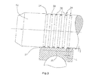
- the motor shaft 12 has six lubricant annular grooves 24 each filled at least half with a corrosion-inhibiting lubricant 28 over the entire circumference.
- the inner ring 20 closes the openings of the annular grooves 24.
- the lubricant 28 ensures the entire lifetime of the Electric motor 10 that the entire match area 26, that is, the entire match-ring memory 27 is always lubricated with a thin film of lubricant. This reduces the mechanical wear of the surfaces involved and directly prevents corrosion.
- the lubricant annular grooves 24 are formed substantially round in cross section, that is, in particular the annular groove bottom 30 is formed round and not rectangular.
- the axial length L of the openings of all annular grooves 24 together is at least 1/3 of the length of the Spieipassungs region 26, ie the area in which the roller bearing inner ring 20 is seated with clearance fit on the motor shaft 12.
- the axial length L of the opening of the lubricant annular groove 24 is more than twice as large as its radial depth T.
Landscapes
- Engineering & Computer Science (AREA)
- General Engineering & Computer Science (AREA)
- Mechanical Engineering (AREA)
- Power Engineering (AREA)
- Motor Or Generator Frames (AREA)
- Rolling Contact Bearings (AREA)
Abstract
Description
- Die Erfindung bezieht sich auf einen Kfz-Aggregat-Elektromotor, der ein Aggregat in einem Kraftfahrzeug mit Verbrennungsmotor antreibt. Das Aggregat kann beispielsweise ein Sekundarfuftgebiase sein.
- Kfz-Aggregat-Elektromotoren sind insbesondere in Kraftfahrzeugen mit Verbrennungsmotor mitunter dauerhaft hohen mechanischen und thermischen Betastungen ausgesetzt. Dies gift insbesondere für Aggregate, die mit Abgas mechanisch und/oder thermisch in Kontakt stehen, wie dies beispielsweise für ein durch einen Elektromotor angetriebenes Sekundärluftgebläse der Fall ist.
- Ein typischer Kfz-Aggregat-Elektromotor weist eine Metall-Motorwelle auf, die durch zwei Wälzlager drehbar gelagert ist, nämlich durch ein Axial/Radial-Wälzlager, das so genannte Festlager, und durch ein Radial-Wälzlager, das so genannte Loslager. Ein Loslager ist erforderlich, um innere axiale Spannungen zu vermeiden. Das Radial-Wälzlager weist einen Innenring aus Metall auf, der mit Spielpassung auf der Motorwelle sitzt, so dass der Innenring, und damit das gesamte Radial-Wälzlager, axial gegen einen gewissen Widerstand verschiebbar ist. Die Verschiebungen ergeben sich beispielsweise aus Vibrationen und aus verschiedenen temperaturbedingten Längenänderungen verschiedener Bauteile des Elektromotors. Durch die ständigen Verschiebungen verschlechtern sich die aufeinander reibenden Oberflächen der Motorwelle und des Wälzlager-Innenrings, was zu so genanntem Passungsrost führt. Zur Vermeidung von Passungsrost wird die Motorwelle beziehungsweise der Wälzlager-Innenring vor der Montage gefettet. Hierdurch kann jedoch Passungsrost bei hoher Beanspruchung auf Dauer nicht vermieden werden.
- Aufgabe der Erfindung ist es demgegenüber, eine Kfz-Aggregat-Elektromotor mit verringertem Passungsrost im Bereich des Radial-Wälzlagers zu schaffen.
- Diese Aufgabe wird erfindungsgemäß gelöst mit den Merkmalen des Patentanspruches 1.
- Gemäß der Erfindung weist die Motorwelle im Bereich des Radial-Wälzlager-Innen rings mindestens eine ringförmige Schmiermittel-Ringnut auf, deren Öffnungsseite durch den Innenring verschlossen ist. Die Ringnut ist mit einem korrosionshemmenden Schmiermittel gefüllt. Im Bereich der Passung ist in der Ringnut also ein Schmiermittel-Depot angelegt, das ausreichend ist, über die gesamte typische Lebenszeit des betreffenden Verbrennungsmotors beziehungsweise Kraftfahrzeugs Passungsrost zuverlässig zu vermeiden.
- Die Ringnut verläuft streng ringförmig, also nicht in einer Schraubenlinie, Hierdurch wird sichergestellt, dass das Schmiermittel in der Ringnut axial nicht wandern kann. Bei Rotation der Motorwelle wird durch die Zentrifugalkräfte das Schmiermittel aus der Ringnut radial auf die zylindrische Innenfläche des Wälziager-Innenrings geschleudert. Auf diese Weise ist sichergestellt, dass im Bereich der Passung stets ein dünner Schmiermittel-Film erhalten bleibt. Vorzugsweise beträgt das Spiel der Spielpassung weniger als 10 µm.
- Vorzugsweise sind in dem Bereich des Innenringes beziehungsweise der Passung mehrere parallele Ringnuten vorgesehen, die alle durch den Wälzlager-Innenring verschlossen sind. Je größer die axiale Länge des Wälzlager-Innen rings ist, desto mehr Ringnuten sind sinnvoll, um die gesamte axiale Länge der Passung zuverlässig und dauerhaft mit Schmiermittel zu versorgen. Besonders bevorzugt sind mindestens drei parallele Ringnuten vorgesehen.
- Gemäß einer bevorzugten Ausgestaltung beträgt die Summe der axialen Länge aller Öffnungen aller Schmiermittel-Ringnuten zusammen mindestens 1/3 der axialen Länge des Innenring. Mit anderen Worten, mindestens 1/3 der axialen Länge des Innenrings wird in Form von Ringnuten für das Verhalten eines Schmiermittel-Depots genutzt.
- Vorzugsweise ist die Schmiermittel-Ringnut im Querschnitt im Wesentlichen rund, und besonders bevorzugt kreisrund ausgebildet. Durch eine runde Ringnut, bei der insbesondere der Nutboden ausgerundet ist, wird sichergestellt, dass auch das Schmiermittel am Nutboden leicht nach radial außen wandern kann. Vorzugsweise ist die axiale Länge der Ringnut-Öffnung mindestens doppelt so groß wie die radiale Tiefe der Ringnut.
- Gemäß einer bevorzugten Ausgestaltung ist mindestens 30 %, bevorzugt mindestens 50 % des Volumens beziehungsweise der Querschnittsfläche der Schmiermittel-Ringnut mit dem korrosionshemmenden Schmiermittel gefüllt. Dies wird durch entsprechende optische Kontrollen bei der Herstellung des Elektromotors sichergestellt, durch die der Schmiermittel-Füllungsgrad der Ringnuten überprüft wird.
- Im Folgenden wird ein Ausführungsbeispiel der Erfindung anhand der Zeichnungen näher erläutert.
- Es zeigen:
- Figur 1
- einen Längsschnitt eines Kfz-Aggregat-Elektromotors mit einem Axial/Radial-Wälzlager und einem Radial-Wälzlager,
- Figur 2
- eine vergrößerte Darstellung des Radial-Wälzlagers des Elektromotors der
Figur 1 , und - Figur 3
- eine vergrößerte Darstellung der Motorwelle im Bereich des Radial-Wälzlagers.
- In der
Figur 1 ist ein Kfz-Aggregat-Elektromotor 10 dargestellt, der beispielsweise zum Antrieb eines Sekundärluftgebläses verwendet wird. Der Elektromotor 10 weist eine Motorwelle 12 aus Metall auf, die durch ein Axial/Radial-Wälzlager 16 und durch ein Radial-Wälzlager 14 gelagert ist. - Das Radial-Wälzlager 14 besteht aus einem Außenring 18, einen Innenring 20 aus Metall und mehreren Wälzkörpern 22. Der Innenring 20 sitzt in einem Spielpassungs-Bereich 26 mit Spielpassung auf der Motorwelle 12, das heißt mit einem Ringspalt 27 beziehungsweise einem Spiel von weniger als 10 µm.
- In dem axialen Spielpassungs-Bereich 26 weist die Motorwelle 12 sechs Schmiermittel-Ringnuten 24 auf, die jeweils mindestens zur Hälfte mit einem korrosionshemmenden Schmiermittel 28 über den gesamten Umfang gefüllt sind. Der Innenring 20 verschließt die Öffnungen der Ringnuten 24. Das Schmiermittel 28 sorgt für die gesamte Lebenszeit des Elektromotors 10 dafür, dass der gesamte Spielpassungs-Bereich 26, das heißt, der gesamte Spielpassungs-Ringsspait 27 stets mit einem dünnen Film des Schmiermittels geschmiert ist. Hierdurch wird zum einen der mechanische Verschleiß der beteiligten Oberflächen verringert und zum anderen Korrosion unmittelbar verhindert.
- Die Schmiermittel-Ringnuten 24 sind im Querschnitt im Wesentlichen rund ausgebildet, das heißt, insbesondere der Ringnut-Boden 30 ist rund und nicht rechteckig ausgeformt. Die axiale Läge L der Öffnungen aller Ringnuten 24 zusammen beträgt mindestens 1/3 der Länge des Spieipassungs-Bereichs 26, also des Bereichs, in dem der Wälzlager-Innenring 20 mit Spielpassung auf der Motorwelle 12 sitzt. Die axiale Länge L der Öffnung der Schmiermittel-Ringnut 24 ist mehr als doppelt so groß wie ihre radiale Tiefe T.
Claims (8)
- Kfz-Aggregat-Elektromotor (10) mit einem Radial-Wälzlager (14), das einen Außenring (18) und einen Metall-Innenring (20) aufweist, wobei der Innenring (20) auf einer Metall-Motorwelle (12) mit Spielpassung befestigt ist,
dadurch gekennzeichnet, dass
die Motorwelle (12) im Bereich (26) des Innenrings (20) mindestens eine ringförmige Schmiermittel-Ringnut (24) aufweist, die durch den Innenring (20) verschlossen ist, und
die Ringnut (24) mit einem korrosionshemmenden Schmiermittel (28) gefüllt ist. - Kfz-Aggregat-Elektromotor (10) nach Anspruch 1, wobei mehrere parallele Schmiermittel-Ringnuten (24) vorgesehen sind, die alle durch den Innenring (20) verschlossen sind.
- Kfz-Aggregat-Elektromotor (10) nach einem der vorangegangenen Ansprüche, wobei das Spiel der Spielpassung weniger als 10 µm beträgt.
- Kfz-Aggregat-Elektromotor (10) nach einem der vorangegangenen Ansprüche, wobei die Schmiermittel-Ringnut (24) im Querschnitt im wesentlichen rund, und besonders bevorzugt kreisrund ausgebindet ist.
- Kfz-Aggregat-Elektromotor (10) nach einem der vorangegangenen Ansprüche, wobei mindestens drei Schmiermittel-Ringnuten (24) vorgesehen sind.
- Kfz-Aggregat-Elektromotor (10) nach einem der vorangegangenen Ansprüche, wobei die Summe der axialen Länge L der Öffnungen aller Schmiermittel-Ringnuten (24) mindestens 1/3 der axialen Länge des Spielpassungs-Bereichs (26) beträgt.
- Kfz-Aggregat-Elektromotor (10) nach einem der vorangegangenen Ansprüche, wobei die axiale Länge L der Öffnung der Schmiermittel-Ringnut (24) mindestens doppelt so groß ist wie die radiale Tiefe T der Ringnut (24).
- Kfz-Aggregat-Elektromotor (10) nach einem der vorangegangenen Ansprüche, wobei mindestens 30 %, bevorzugt mindestens 50 % des Volumens der Schmiermittel-Ringnut (24) mit dem korrosionshemmenden Schmiermittel (28) gefüllt ist.
Priority Applications (1)
| Application Number | Priority Date | Filing Date | Title |
|---|---|---|---|
| EP10170549.9A EP2410638B1 (de) | 2010-07-23 | 2010-07-23 | Kfz-Aggregat-Elektromotor |
Applications Claiming Priority (1)
| Application Number | Priority Date | Filing Date | Title |
|---|---|---|---|
| EP10170549.9A EP2410638B1 (de) | 2010-07-23 | 2010-07-23 | Kfz-Aggregat-Elektromotor |
Publications (2)
| Publication Number | Publication Date |
|---|---|
| EP2410638A1 true EP2410638A1 (de) | 2012-01-25 |
| EP2410638B1 EP2410638B1 (de) | 2013-04-24 |
Family
ID=42676924
Family Applications (1)
| Application Number | Title | Priority Date | Filing Date |
|---|---|---|---|
| EP10170549.9A Active EP2410638B1 (de) | 2010-07-23 | 2010-07-23 | Kfz-Aggregat-Elektromotor |
Country Status (1)
| Country | Link |
|---|---|
| EP (1) | EP2410638B1 (de) |
Families Citing this family (1)
| Publication number | Priority date | Publication date | Assignee | Title |
|---|---|---|---|---|
| CN107257170A (zh) * | 2017-08-17 | 2017-10-17 | 南通奥里斯特机械有限公司 | 一种润滑寿命强的电机转子 |
Citations (3)
| Publication number | Priority date | Publication date | Assignee | Title |
|---|---|---|---|---|
| DE3810299A1 (de) * | 1987-03-26 | 1988-10-13 | Mitsubishi Electric Corp | Vorrichtung mit einem lager zur verschiebbaren stuetzung einer ritzelwelle |
| WO2007065749A1 (de) * | 2005-12-06 | 2007-06-14 | Robert Bosch Gmbh | Lagersystem für einen elektromotor |
| DE202009011583U1 (de) * | 2009-08-21 | 2010-01-07 | Getrag Innovations Gmbh | Lageranordnung |
-
2010
- 2010-07-23 EP EP10170549.9A patent/EP2410638B1/de active Active
Patent Citations (3)
| Publication number | Priority date | Publication date | Assignee | Title |
|---|---|---|---|---|
| DE3810299A1 (de) * | 1987-03-26 | 1988-10-13 | Mitsubishi Electric Corp | Vorrichtung mit einem lager zur verschiebbaren stuetzung einer ritzelwelle |
| WO2007065749A1 (de) * | 2005-12-06 | 2007-06-14 | Robert Bosch Gmbh | Lagersystem für einen elektromotor |
| DE202009011583U1 (de) * | 2009-08-21 | 2010-01-07 | Getrag Innovations Gmbh | Lageranordnung |
Also Published As
| Publication number | Publication date |
|---|---|
| EP2410638B1 (de) | 2013-04-24 |
Similar Documents
| Publication | Publication Date | Title |
|---|---|---|
| DE19900858B4 (de) | Kegelrollenlager | |
| DE602004012546T2 (de) | Vakuumpumpe | |
| DE102016214018B4 (de) | Lageranordnung, insbesondere für eine Strömungsmaschine, und Strömungsmaschine mit einer derartigen Lageranordnung | |
| EP0227991A2 (de) | Aerodynamisches Gleitlager | |
| DE102018104685A1 (de) | Antriebsvorrichtung mit einem Elektromotor und einem Getriebe | |
| DE212013000161U1 (de) | Schrägkugellager und Kombinationslager | |
| WO2011000645A1 (de) | Lageranordnung mit einer welle und einem nadellager | |
| DE102007030217A9 (de) | Käfig | |
| EP3306142A1 (de) | Lagerung für ein planetenrad eines planetengetriebes | |
| DE112021005705T5 (de) | Wälzlager | |
| EP2019930A1 (de) | Wälzlager mit reduzierter käfigtaschenluft | |
| DE102016200939B4 (de) | Lagereinheit für einen Abgasturbolader oder eine Abgasnutzturbine | |
| DE19855420C2 (de) | Schwerer Drehschwingungsdämpfer | |
| DE112011104991T5 (de) | Wälzlager mit interner Schmierung | |
| DE102010019130A1 (de) | Zylinderkopf | |
| WO2010037710A1 (de) | Halteplatte für lager | |
| DE102016220460A1 (de) | Lageranordnung für einen Turbolader mit Verdrehsicherung | |
| EP2410638B1 (de) | Kfz-Aggregat-Elektromotor | |
| DE102007044702A1 (de) | Lager | |
| DE102013011102A1 (de) | Lagerungsanordnung einer Welle an einem Gehäuse für eine Maschine | |
| WO2019214883A1 (de) | Lagereinrichtung mit einer strukturierten welle | |
| DE102017222792A1 (de) | Lageranordnung | |
| DE102004040224B4 (de) | Wälzlager | |
| DE112019001412T5 (de) | Lagerungsstruktur | |
| DE112019001394T5 (de) | Lagertragaufbau |
Legal Events
| Date | Code | Title | Description |
|---|---|---|---|
| AK | Designated contracting states |
Kind code of ref document: A1 Designated state(s): AL AT BE BG CH CY CZ DE DK EE ES FI FR GB GR HR HU IE IS IT LI LT LU LV MC MK MT NL NO PL PT RO SE SI SK SM TR |
|
| AX | Request for extension of the european patent |
Extension state: BA ME RS |
|
| PUAI | Public reference made under article 153(3) epc to a published international application that has entered the european phase |
Free format text: ORIGINAL CODE: 0009012 |
|
| 17P | Request for examination filed |
Effective date: 20120719 |
|
| GRAP | Despatch of communication of intention to grant a patent |
Free format text: ORIGINAL CODE: EPIDOSNIGR1 |
|
| GRAS | Grant fee paid |
Free format text: ORIGINAL CODE: EPIDOSNIGR3 |
|
| GRAA | (expected) grant |
Free format text: ORIGINAL CODE: 0009210 |
|
| AK | Designated contracting states |
Kind code of ref document: B1 Designated state(s): AL AT BE BG CH CY CZ DE DK EE ES FI FR GB GR HR HU IE IS IT LI LT LU LV MC MK MT NL NO PL PT RO SE SI SK SM TR |
|
| REG | Reference to a national code |
Ref country code: GB Ref legal event code: FG4D Free format text: NOT ENGLISH |
|
| REG | Reference to a national code |
Ref country code: CH Ref legal event code: EP |
|
| REG | Reference to a national code |
Ref country code: AT Ref legal event code: REF Ref document number: 609126 Country of ref document: AT Kind code of ref document: T Effective date: 20130515 |
|
| REG | Reference to a national code |
Ref country code: IE Ref legal event code: FG4D Free format text: LANGUAGE OF EP DOCUMENT: GERMAN |
|
| REG | Reference to a national code |
Ref country code: DE Ref legal event code: R096 Ref document number: 502010003065 Country of ref document: DE Effective date: 20130620 |
|
| REG | Reference to a national code |
Ref country code: LT Ref legal event code: MG4D |
|
| REG | Reference to a national code |
Ref country code: NL Ref legal event code: VDEP Effective date: 20130424 |
|
| PG25 | Lapsed in a contracting state [announced via postgrant information from national office to epo] |
Ref country code: LT Free format text: LAPSE BECAUSE OF FAILURE TO SUBMIT A TRANSLATION OF THE DESCRIPTION OR TO PAY THE FEE WITHIN THE PRESCRIBED TIME-LIMIT Effective date: 20130424 Ref country code: IS Free format text: LAPSE BECAUSE OF FAILURE TO SUBMIT A TRANSLATION OF THE DESCRIPTION OR TO PAY THE FEE WITHIN THE PRESCRIBED TIME-LIMIT Effective date: 20130824 Ref country code: FI Free format text: LAPSE BECAUSE OF FAILURE TO SUBMIT A TRANSLATION OF THE DESCRIPTION OR TO PAY THE FEE WITHIN THE PRESCRIBED TIME-LIMIT Effective date: 20130424 Ref country code: SE Free format text: LAPSE BECAUSE OF FAILURE TO SUBMIT A TRANSLATION OF THE DESCRIPTION OR TO PAY THE FEE WITHIN THE PRESCRIBED TIME-LIMIT Effective date: 20130424 Ref country code: SI Free format text: LAPSE BECAUSE OF FAILURE TO SUBMIT A TRANSLATION OF THE DESCRIPTION OR TO PAY THE FEE WITHIN THE PRESCRIBED TIME-LIMIT Effective date: 20130424 Ref country code: GR Free format text: LAPSE BECAUSE OF FAILURE TO SUBMIT A TRANSLATION OF THE DESCRIPTION OR TO PAY THE FEE WITHIN THE PRESCRIBED TIME-LIMIT Effective date: 20130725 Ref country code: PT Free format text: LAPSE BECAUSE OF FAILURE TO SUBMIT A TRANSLATION OF THE DESCRIPTION OR TO PAY THE FEE WITHIN THE PRESCRIBED TIME-LIMIT Effective date: 20130826 Ref country code: NO Free format text: LAPSE BECAUSE OF FAILURE TO SUBMIT A TRANSLATION OF THE DESCRIPTION OR TO PAY THE FEE WITHIN THE PRESCRIBED TIME-LIMIT Effective date: 20130724 Ref country code: ES Free format text: LAPSE BECAUSE OF FAILURE TO SUBMIT A TRANSLATION OF THE DESCRIPTION OR TO PAY THE FEE WITHIN THE PRESCRIBED TIME-LIMIT Effective date: 20130804 |
|
| PG25 | Lapsed in a contracting state [announced via postgrant information from national office to epo] |
Ref country code: PL Free format text: LAPSE BECAUSE OF FAILURE TO SUBMIT A TRANSLATION OF THE DESCRIPTION OR TO PAY THE FEE WITHIN THE PRESCRIBED TIME-LIMIT Effective date: 20130424 Ref country code: BG Free format text: LAPSE BECAUSE OF FAILURE TO SUBMIT A TRANSLATION OF THE DESCRIPTION OR TO PAY THE FEE WITHIN THE PRESCRIBED TIME-LIMIT Effective date: 20130724 Ref country code: LV Free format text: LAPSE BECAUSE OF FAILURE TO SUBMIT A TRANSLATION OF THE DESCRIPTION OR TO PAY THE FEE WITHIN THE PRESCRIBED TIME-LIMIT Effective date: 20130424 Ref country code: HR Free format text: LAPSE BECAUSE OF FAILURE TO SUBMIT A TRANSLATION OF THE DESCRIPTION OR TO PAY THE FEE WITHIN THE PRESCRIBED TIME-LIMIT Effective date: 20130424 Ref country code: CY Free format text: LAPSE BECAUSE OF FAILURE TO SUBMIT A TRANSLATION OF THE DESCRIPTION OR TO PAY THE FEE WITHIN THE PRESCRIBED TIME-LIMIT Effective date: 20130424 |
|
| BERE | Be: lapsed |
Owner name: PIERBURG PUMP TECHNOLOGY G.M.B.H. Effective date: 20130731 |
|
| PG25 | Lapsed in a contracting state [announced via postgrant information from national office to epo] |
Ref country code: SK Free format text: LAPSE BECAUSE OF FAILURE TO SUBMIT A TRANSLATION OF THE DESCRIPTION OR TO PAY THE FEE WITHIN THE PRESCRIBED TIME-LIMIT Effective date: 20130424 Ref country code: DK Free format text: LAPSE BECAUSE OF FAILURE TO SUBMIT A TRANSLATION OF THE DESCRIPTION OR TO PAY THE FEE WITHIN THE PRESCRIBED TIME-LIMIT Effective date: 20130424 Ref country code: EE Free format text: LAPSE BECAUSE OF FAILURE TO SUBMIT A TRANSLATION OF THE DESCRIPTION OR TO PAY THE FEE WITHIN THE PRESCRIBED TIME-LIMIT Effective date: 20130424 Ref country code: CZ Free format text: LAPSE BECAUSE OF FAILURE TO SUBMIT A TRANSLATION OF THE DESCRIPTION OR TO PAY THE FEE WITHIN THE PRESCRIBED TIME-LIMIT Effective date: 20130424 |
|
| PG25 | Lapsed in a contracting state [announced via postgrant information from national office to epo] |
Ref country code: NL Free format text: LAPSE BECAUSE OF FAILURE TO SUBMIT A TRANSLATION OF THE DESCRIPTION OR TO PAY THE FEE WITHIN THE PRESCRIBED TIME-LIMIT Effective date: 20130424 Ref country code: MC Free format text: LAPSE BECAUSE OF FAILURE TO SUBMIT A TRANSLATION OF THE DESCRIPTION OR TO PAY THE FEE WITHIN THE PRESCRIBED TIME-LIMIT Effective date: 20130424 Ref country code: RO Free format text: LAPSE BECAUSE OF FAILURE TO SUBMIT A TRANSLATION OF THE DESCRIPTION OR TO PAY THE FEE WITHIN THE PRESCRIBED TIME-LIMIT Effective date: 20130424 Ref country code: IT Free format text: LAPSE BECAUSE OF FAILURE TO SUBMIT A TRANSLATION OF THE DESCRIPTION OR TO PAY THE FEE WITHIN THE PRESCRIBED TIME-LIMIT Effective date: 20130424 |
|
| PLBE | No opposition filed within time limit |
Free format text: ORIGINAL CODE: 0009261 |
|
| STAA | Information on the status of an ep patent application or granted ep patent |
Free format text: STATUS: NO OPPOSITION FILED WITHIN TIME LIMIT |
|
| 26N | No opposition filed |
Effective date: 20140127 |
|
| REG | Reference to a national code |
Ref country code: IE Ref legal event code: MM4A |
|
| REG | Reference to a national code |
Ref country code: FR Ref legal event code: ST Effective date: 20140331 |
|
| PG25 | Lapsed in a contracting state [announced via postgrant information from national office to epo] |
Ref country code: BE Free format text: LAPSE BECAUSE OF NON-PAYMENT OF DUE FEES Effective date: 20130731 |
|
| REG | Reference to a national code |
Ref country code: DE Ref legal event code: R097 Ref document number: 502010003065 Country of ref document: DE Effective date: 20140127 |
|
| PG25 | Lapsed in a contracting state [announced via postgrant information from national office to epo] |
Ref country code: FR Free format text: LAPSE BECAUSE OF NON-PAYMENT OF DUE FEES Effective date: 20130731 |
|
| PG25 | Lapsed in a contracting state [announced via postgrant information from national office to epo] |
Ref country code: IE Free format text: LAPSE BECAUSE OF NON-PAYMENT OF DUE FEES Effective date: 20130723 |
|
| REG | Reference to a national code |
Ref country code: CH Ref legal event code: PL |
|
| GBPC | Gb: european patent ceased through non-payment of renewal fee |
Effective date: 20140723 |
|
| PG25 | Lapsed in a contracting state [announced via postgrant information from national office to epo] |
Ref country code: LI Free format text: LAPSE BECAUSE OF NON-PAYMENT OF DUE FEES Effective date: 20140731 Ref country code: CH Free format text: LAPSE BECAUSE OF NON-PAYMENT OF DUE FEES Effective date: 20140731 |
|
| PG25 | Lapsed in a contracting state [announced via postgrant information from national office to epo] |
Ref country code: GB Free format text: LAPSE BECAUSE OF NON-PAYMENT OF DUE FEES Effective date: 20140723 Ref country code: SM Free format text: LAPSE BECAUSE OF FAILURE TO SUBMIT A TRANSLATION OF THE DESCRIPTION OR TO PAY THE FEE WITHIN THE PRESCRIBED TIME-LIMIT Effective date: 20130424 |
|
| PG25 | Lapsed in a contracting state [announced via postgrant information from national office to epo] |
Ref country code: TR Free format text: LAPSE BECAUSE OF FAILURE TO SUBMIT A TRANSLATION OF THE DESCRIPTION OR TO PAY THE FEE WITHIN THE PRESCRIBED TIME-LIMIT Effective date: 20130424 Ref country code: MT Free format text: LAPSE BECAUSE OF FAILURE TO SUBMIT A TRANSLATION OF THE DESCRIPTION OR TO PAY THE FEE WITHIN THE PRESCRIBED TIME-LIMIT Effective date: 20130424 |
|
| PG25 | Lapsed in a contracting state [announced via postgrant information from national office to epo] |
Ref country code: HU Free format text: LAPSE BECAUSE OF FAILURE TO SUBMIT A TRANSLATION OF THE DESCRIPTION OR TO PAY THE FEE WITHIN THE PRESCRIBED TIME-LIMIT; INVALID AB INITIO Effective date: 20100723 Ref country code: MK Free format text: LAPSE BECAUSE OF FAILURE TO SUBMIT A TRANSLATION OF THE DESCRIPTION OR TO PAY THE FEE WITHIN THE PRESCRIBED TIME-LIMIT Effective date: 20130424 Ref country code: LU Free format text: LAPSE BECAUSE OF NON-PAYMENT OF DUE FEES Effective date: 20130723 |
|
| REG | Reference to a national code |
Ref country code: AT Ref legal event code: MM01 Ref document number: 609126 Country of ref document: AT Kind code of ref document: T Effective date: 20150723 |
|
| PG25 | Lapsed in a contracting state [announced via postgrant information from national office to epo] |
Ref country code: AT Free format text: LAPSE BECAUSE OF NON-PAYMENT OF DUE FEES Effective date: 20150723 |
|
| PG25 | Lapsed in a contracting state [announced via postgrant information from national office to epo] |
Ref country code: AL Free format text: LAPSE BECAUSE OF FAILURE TO SUBMIT A TRANSLATION OF THE DESCRIPTION OR TO PAY THE FEE WITHIN THE PRESCRIBED TIME-LIMIT Effective date: 20130424 |
|
| REG | Reference to a national code |
Ref country code: DE Ref legal event code: R082 Ref document number: 502010003065 Country of ref document: DE Representative=s name: TERPATENT PARTGMBB, DE Ref country code: DE Ref legal event code: R082 Ref document number: 502010003065 Country of ref document: DE Representative=s name: TERPATENT PATENTANWAELTE TER SMITTEN EBERLEIN-, DE |
|
| PGFP | Annual fee paid to national office [announced via postgrant information from national office to epo] |
Ref country code: DE Payment date: 20250722 Year of fee payment: 16 |
|
| REG | Reference to a national code |
Ref country code: DE Ref legal event code: R082 Ref document number: 502010003065 Country of ref document: DE |