EP2410629A1 - Input/output device and remote controller - Google Patents
Input/output device and remote controller Download PDFInfo
- Publication number
- EP2410629A1 EP2410629A1 EP09841835A EP09841835A EP2410629A1 EP 2410629 A1 EP2410629 A1 EP 2410629A1 EP 09841835 A EP09841835 A EP 09841835A EP 09841835 A EP09841835 A EP 09841835A EP 2410629 A1 EP2410629 A1 EP 2410629A1
- Authority
- EP
- European Patent Office
- Prior art keywords
- unit
- input
- output
- power
- main body
- Prior art date
- Legal status (The legal status is an assumption and is not a legal conclusion. Google has not performed a legal analysis and makes no representation as to the accuracy of the status listed.)
- Granted
Links
- 239000003990 capacitor Substances 0.000 claims description 19
- 230000005674 electromagnetic induction Effects 0.000 claims description 7
- 230000001360 synchronised effect Effects 0.000 claims 2
- 230000003287 optical effect Effects 0.000 claims 1
- 238000009413 insulation Methods 0.000 abstract description 14
- 230000006698 induction Effects 0.000 abstract description 13
- 230000003014 reinforcing effect Effects 0.000 abstract description 2
- 230000005540 biological transmission Effects 0.000 description 65
- 238000010586 diagram Methods 0.000 description 25
- 238000000034 method Methods 0.000 description 19
- 238000009499 grossing Methods 0.000 description 13
- 239000000284 extract Substances 0.000 description 8
- 230000010355 oscillation Effects 0.000 description 7
- 230000015556 catabolic process Effects 0.000 description 6
- 238000001514 detection method Methods 0.000 description 6
- 230000003321 amplification Effects 0.000 description 4
- 239000004020 conductor Substances 0.000 description 4
- 239000004973 liquid crystal related substance Substances 0.000 description 4
- 238000003199 nucleic acid amplification method Methods 0.000 description 4
- 230000000087 stabilizing effect Effects 0.000 description 4
- 230000002159 abnormal effect Effects 0.000 description 3
- 239000000696 magnetic material Substances 0.000 description 3
- 230000010363 phase shift Effects 0.000 description 3
- 239000000463 material Substances 0.000 description 2
- 230000004044 response Effects 0.000 description 2
- 229910000859 α-Fe Inorganic materials 0.000 description 2
- 240000007594 Oryza sativa Species 0.000 description 1
- 235000007164 Oryza sativa Nutrition 0.000 description 1
- 238000010411 cooking Methods 0.000 description 1
- 230000006870 function Effects 0.000 description 1
- 238000002347 injection Methods 0.000 description 1
- 239000007924 injection Substances 0.000 description 1
- 230000015654 memory Effects 0.000 description 1
- 239000002184 metal Substances 0.000 description 1
- 235000009566 rice Nutrition 0.000 description 1
- 230000035945 sensitivity Effects 0.000 description 1
Images


Classifications
-
- H—ELECTRICITY
- H04—ELECTRIC COMMUNICATION TECHNIQUE
- H04L—TRANSMISSION OF DIGITAL INFORMATION, e.g. TELEGRAPHIC COMMUNICATION
- H04L12/00—Data switching networks
- H04L12/28—Data switching networks characterised by path configuration, e.g. LAN [Local Area Networks] or WAN [Wide Area Networks]
- H04L12/2803—Home automation networks
- H04L12/2816—Controlling appliance services of a home automation network by calling their functionalities
- H04L12/282—Controlling appliance services of a home automation network by calling their functionalities based on user interaction within the home
-
- H—ELECTRICITY
- H02—GENERATION; CONVERSION OR DISTRIBUTION OF ELECTRIC POWER
- H02J—CIRCUIT ARRANGEMENTS OR SYSTEMS FOR SUPPLYING OR DISTRIBUTING ELECTRIC POWER; SYSTEMS FOR STORING ELECTRIC ENERGY
- H02J50/00—Circuit arrangements or systems for wireless supply or distribution of electric power
- H02J50/10—Circuit arrangements or systems for wireless supply or distribution of electric power using inductive coupling
- H02J50/12—Circuit arrangements or systems for wireless supply or distribution of electric power using inductive coupling of the resonant type
-
- H—ELECTRICITY
- H02—GENERATION; CONVERSION OR DISTRIBUTION OF ELECTRIC POWER
- H02J—CIRCUIT ARRANGEMENTS OR SYSTEMS FOR SUPPLYING OR DISTRIBUTING ELECTRIC POWER; SYSTEMS FOR STORING ELECTRIC ENERGY
- H02J50/00—Circuit arrangements or systems for wireless supply or distribution of electric power
- H02J50/80—Circuit arrangements or systems for wireless supply or distribution of electric power involving the exchange of data, concerning supply or distribution of electric power, between transmitting devices and receiving devices
-
- H—ELECTRICITY
- H04—ELECTRIC COMMUNICATION TECHNIQUE
- H04L—TRANSMISSION OF DIGITAL INFORMATION, e.g. TELEGRAPHIC COMMUNICATION
- H04L12/00—Data switching networks
- H04L12/28—Data switching networks characterised by path configuration, e.g. LAN [Local Area Networks] or WAN [Wide Area Networks]
- H04L12/2803—Home automation networks
- H04L2012/284—Home automation networks characterised by the type of medium used
- H04L2012/2843—Mains power line
-
- H—ELECTRICITY
- H04—ELECTRIC COMMUNICATION TECHNIQUE
- H04L—TRANSMISSION OF DIGITAL INFORMATION, e.g. TELEGRAPHIC COMMUNICATION
- H04L12/00—Data switching networks
- H04L12/28—Data switching networks characterised by path configuration, e.g. LAN [Local Area Networks] or WAN [Wide Area Networks]
- H04L12/2803—Home automation networks
- H04L2012/2847—Home automation networks characterised by the type of home appliance used
- H04L2012/285—Generic home appliances, e.g. refrigerators
-
- Y—GENERAL TAGGING OF NEW TECHNOLOGICAL DEVELOPMENTS; GENERAL TAGGING OF CROSS-SECTIONAL TECHNOLOGIES SPANNING OVER SEVERAL SECTIONS OF THE IPC; TECHNICAL SUBJECTS COVERED BY FORMER USPC CROSS-REFERENCE ART COLLECTIONS [XRACs] AND DIGESTS
- Y02—TECHNOLOGIES OR APPLICATIONS FOR MITIGATION OR ADAPTATION AGAINST CLIMATE CHANGE
- Y02B—CLIMATE CHANGE MITIGATION TECHNOLOGIES RELATED TO BUILDINGS, e.g. HOUSING, HOUSE APPLIANCES OR RELATED END-USER APPLICATIONS
- Y02B70/00—Technologies for an efficient end-user side electric power management and consumption
- Y02B70/30—Systems integrating technologies related to power network operation and communication or information technologies for improving the carbon footprint of the management of residential or tertiary loads, i.e. smart grids as climate change mitigation technology in the buildings sector, including also the last stages of power distribution and the control, monitoring or operating management systems at local level
-
- Y—GENERAL TAGGING OF NEW TECHNOLOGICAL DEVELOPMENTS; GENERAL TAGGING OF CROSS-SECTIONAL TECHNOLOGIES SPANNING OVER SEVERAL SECTIONS OF THE IPC; TECHNICAL SUBJECTS COVERED BY FORMER USPC CROSS-REFERENCE ART COLLECTIONS [XRACs] AND DIGESTS
- Y04—INFORMATION OR COMMUNICATION TECHNOLOGIES HAVING AN IMPACT ON OTHER TECHNOLOGY AREAS
- Y04S—SYSTEMS INTEGRATING TECHNOLOGIES RELATED TO POWER NETWORK OPERATION, COMMUNICATION OR INFORMATION TECHNOLOGIES FOR IMPROVING THE ELECTRICAL POWER GENERATION, TRANSMISSION, DISTRIBUTION, MANAGEMENT OR USAGE, i.e. SMART GRIDS
- Y04S20/00—Management or operation of end-user stationary applications or the last stages of power distribution; Controlling, monitoring or operating thereof
- Y04S20/20—End-user application control systems
Definitions
- the present invention relates to an input/output apparatus and a remote control apparatus that are equipped with electric apparatuses, such as household electrical appliances and air conditioners.
- Some air conditioners of the related art equip with a wireless remote controller capable of operating (operation, such as driving or stopping) an indoor unit through the wired remote controller instead of a wired remote controller connected through a communication line to an indoor unit.
- a wireless remote controller capable of operating (operation, such as driving or stopping) an indoor unit through the wired remote controller instead of a wired remote controller connected through a communication line to an indoor unit.
- the most recent operation is selected with a higher priority (see, for example, Patent Document 1).
- the present invention has been achieved to solve problems such as those described above, and has an object to provide an input/output apparatus and a remote control apparatus in which electric shock can be prevented without reinforcing the insulation of a power-supply unit and to which a USB, a LAN, and the like can be connected.
- An input/output apparatus is an input/output apparatus that inputs and outputs a signal to and from an electric apparatus, including: at least one resonance circuit formed of a coil and a capacitor; power receiving means in which electric power obtained from the resonance circuit using electromagnetic induction is made to be a power supply of the present apparatus; and communication means that transmits and receives a signal to and from the electric apparatus by using the resonance circuit.
- the input/output apparatus is insulated from a power supply of the electric apparatus.
- a remote control apparatus is a remote control apparatus that operates electric apparatuses through electric wiring and has an internal I/F unit which inputs and outputs a signal to and from the present apparatus.
- the I/F unit includes input/output means for transmitting and receiving a signal to and from the outside, at least one resonance circuit formed of a coil and a capacitor, power receiving means in which electric power obtained from the resonance circuit using electromagnetic induction is made to be a power supply of the present I/F unit, and communication means for transmitting and receiving a signal to and from the present apparatus by using the resonance circuit.
- the input/output apparatus since the input/output apparatus includes a resonance circuit, power receiving means in which electric power obtained from the resonance circuit using electromagnetic induction is made to be a power supply of the present, and communication means that transmits and receives a signal to and from the electric apparatus by using the resonance circuit, it becomes possible to insulate the input/output apparatus from a power supply of the electric apparatus, thereby removing the need to take measures to reinforce insulation for the power supply. Furthermore, it is possible to prevent a user from being electrically shocked due to the insulation breakdown of the power supply of the electric apparatus, and in addition, since the input/output apparatus is insulated from the electric apparatus in the manner described above, connection of a USB, a LAN, and the like is made possible.
- the I/F unit provided in the remote controller main body includes a resonance circuit, power receiving means for using electric power obtained from the resonance circuit by using electromagnetic induction as the power supply of the present I/F unit, and communication means for transmitting and receiving a signal to and from the present apparatus by using the resonance circuit, it becomes possible to insulate the I/F unit from the power supply of the remote control apparatus, thereby removing the need to take measures to reinforce insulation for the power supply. Furthermore, it is possible to prevent the user from being electrically shocked due to insulation breakdown of the power supply of the remote control apparatus, and in addition, the I/F unit is insulated from the remote controller main body in the manner described above, thereby enabling connection of a USB, a LAN, and the like.
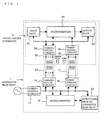
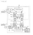
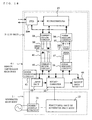
- Fig. 1 is a block diagram illustrating an example of the configuration of an input/output apparatus according to Embodiment 1 of the present invention.
- an electric apparatus hereinafter referred to as an "apparatus main body 1" of a household electrical appliance, such as, for example, a rice cooker and an electromagnetic cooking device includes a power-supply circuit 11 connected to a commercial power supply, a microcomputer 12, a functional unit of the apparatus main body 13, a communication circuit 14 having a transmission and reception unit 15, a power feeding circuit 16 having a feeding unit 17, and an input/output apparatus 2.
- the power-supply circuit 11 When a commercial power supply is applied, the power-supply circuit 11 generates a predetermined constant voltage to supply to the microcomputer 12, the functional unit of the apparatus main body 13, the communication circuit 14, and the power feeding circuit 16 respectively.
- the microcomputer 12 When the power supply is switched on, the microcomputer 12 causes the power feeding circuit 16 to operate so as to cause the feeding unit 17 to generate an AC magnetic field, so that the input/output apparatus 2 side is made to receive an AC voltage.
- the functional unit of the apparatus main body 13 is a circuit unit for achieving various functions included in the apparatus main body 1, and operates under the control of the microcomputer 12.
- the input/output apparatus 2 includes an input unit 21 having various operation switches (not shown), a microcomputer 22, an output unit 23 having an LED and a liquid-crystal display (not shown), a communication circuit 24 (communication means) having a transmission and reception unit 25 arranged so as to face the transmission and reception unit 15, and a power-supply circuit 26 (power receiving means) having a power receiving unit 27 arranged so as to face the feeding unit 17.
- the power-supply circuit 26 When an AC voltage is generated in the power receiving unit 27 due to the induction of an AC magnetic field, the power-supply circuit 26 generates a predetermined constant voltage on the basis of the AC voltage, and supplies it to the input unit 21, the microcomputer 22, the output unit 23, and the communication circuit 24.
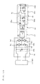
- Fig. 19 is a circuit diagram illustrating the configuration of a power feeding circuit of an apparatus main body and a power-supply circuit of an input/output apparatus.
- the power feeding circuit 16 of the apparatus main body 1 has, at its output end, the feeding unit 17 of a series resonance circuit in which a capacitor C2 and a coil L1 are connected in series with each other, and includes a smoothing circuit 16a formed of a smoothing capacitor C1 connected between the output ends of the power-supply circuit 11, and a full-bridge type inverter 16b.
- switching elements Tr1 and Tr4 are turned on, and switching elements Tr2 and Tr4 are turned off under the control of the microcomputer 12.
- the switching elements Tr1 and Tr4 are turned on, the switching elements Tr2 and Tr4 are turned off, and this operation is repeatedly performed at the period of the resonance frequency of the series resonance circuit, and the AC electric current is supplied to the feeding unit 17, causing the coil L1 of the feeding unit 17 to generate an AC magnetic field.
- the power-supply circuit 26 of the input/output apparatus 2 has, at its input end, the power receiving unit 27 of a parallel resonance circuit in which a coil L2 and a capacitor C3 are connected in parallel with each other, and includes a diode 26a for rectifying the AC voltage that is generated by the induction of the AC magnetic field on the feeding unit 17 side in the power receiving unit 27, a smoothing circuit 26b formed of a capacitor C4 and a smoothing capacitor C5, a power source stabilizing circuit 26c formed of a power-supply regulator IC, a capacitor C6, and a smoothing capacitor C7, and a connector 26d provided at the output end of the power source stabilizing circuit 26c.
- the above-mentioned smoothing circuit 26b smoothes the commercial frequency components of the rectified voltage from the diode 26a by using the capacitor C4 and the smoothing capacitor C5.
- the power source stabilizing circuit 26c stabilizes the output voltage of the smoothing circuit 26b by using a power-supply regulator IC, and suppresses a voltage variation due to a sudden load variation by the capacitor C6 and the smoothing capacitor C7.
- the coil L1 of the feeding unit 17 is separated from the coil L2 of the power receiving unit 27 by a distance in the range of, for example, several mm to several cm.
- the spacing is determined by the injection electric power of the power feeding circuit 16, the electric power consumption on the input/output apparatus 2 side, and adjustment of the configuration (for example, the area of the coils L1 and L2) of the feeding unit 17 and the power receiving unit 27.
- an air-core coil an air-core coil in which a magnetic material is arranged on a portion of the end surface thereof or in which a conductor is wound around a ferrite material, or the like is used.
- a conductor circuit in the form of a flexible sheet, or a sheet-like conductor circuit in which a similar sheet-like magnetic material is arranged on one side thereof may be used.
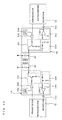
- Fig. 20 is a circuit diagram illustrating the configuration of each of communication circuits of an apparatus main body and an input/output apparatus.
- the communication circuit 14 of the apparatus main body 1 has the transmission and reception unit 15 of a parallel resonance circuit in which a capacitor and a coil are connected in parallel with each other, and includes a carrier oscillation unit 14a for oscillating a high-frequency signal, a logical product circuit 14b for generating the logical product of the high-frequency signal from the carrier oscillation unit 14a and data from the microcomputer 12 so as to be subjected to amplitude-shift keying (ASK), an amplification circuit 14c for amplifying the output signal of the logical product circuit 14b to predetermined electric power so as to excite the transmission and reception unit 15 and for causing a high-frequency magnetic field to be generated from the coil of the transmission and reception unit 15, a detection circuit 14d for smoothing the high-frequencyAC voltage generated
- ASK amplitude-shift keying
- the communication circuit 24 of the input/output apparatus 2 has the transmission and reception unit 25 of a parallel resonance circuit in which a capacitor and a coil are connected in parallel to each other, and includes a carrier oscillation unit 24a for oscillating a high-frequency signal, a logical product circuit 24b for generating the logical product of the high-frequency signal from the carrier oscillation unit 24a and data from the microcomputer 22 so as to be subjected to amplitude-shift keying (ASK), an amplification circuit 24c for amplifying the output signal of the logical product circuit 24b to predetermined electric power so as to excite the transmission and reception unit 25 and causing a high-frequency magnetic field to be generated from the coil of the transmission and reception unit 25, a detection circuit 24d for smoothing the high-frequency AC voltage generated in the transmission and reception unit 25 by the induction of the high-frequency magnetic field on the transmission and reception unit 15 side and removing high frequency components, and a comparator 24e for comparing the signal from the detection circuit 24d with a
- the coils of the communication circuits 14 and 24 are separated from each other by a distance in the range of several mm to several cm, and the spacing is determined by the transmission and reception level, adjustment of the reception sensitivity for the signal and adjustment of the configuration of each of the coils of the transmission and reception units 15 and 25.
- the coil in general, an air-core coil, an air-core coil in which a magnetic material is arranged on a portion of the end surface thereof or in which a conductor is wound around a ferrite material, or the like is used.
- the power-supply circuit 11 when a commercial power supply is applied to the power-supply circuit 11 of the apparatus main body 1, as described above, the power-supply circuit 11 generates a predetermined constant voltage, and supplies it to the microcomputer 12, the functional unit of the apparatus main body 13, the communication circuit 14, and the power feeding circuit 16 inside the apparatus main body 1.
- the microcomputer 12 When the power supply is switched on, the microcomputer 12 causes the power feeding circuit 16 to operate. That is, the inverter 16b of an power feeding circuit 16 is driven, and an alternating electric current is supplied to the feeding unit 17 so that the coil L1 is made to generate an AC magnetic field.
- the power-supply circuit 26 of the input/output apparatus 2 rectifies the AC voltage from the power receiving unit 27 so as to smooth the AC voltage, makes the AC voltage be a predetermined constant voltage, and supplies it to the input unit 21, the microcomputer 22, the output unit 23, and the communication circuit 24 inside the input/output apparatus 2, thereby causing them to enter an operable state.
- the output unit 23 turns on an LED (not shown) so as to indicate that power is being applied.
- the microcomputer 22 When a signal based on a switch operation is output to the microcomputer 22 from the input unit 21 while power is supplied to the input/output apparatus 2, the microcomputer 22 outputs data based on the signal from the input unit 21 to the communication circuit 24 so as to be operated.
- the communication circuit 24 generates the logical product of the high-frequency signal of the carrier oscillation unit 24a and the data from the microcomputer 22 so as to be subjected to amplitude-shift keying, amplifies the result, excites the transmission and reception unit 25, and causes a high-frequency magnetic field to be generated from the transmission and reception unit 25.
- the communication circuit 14 of the apparatus main body 1 smoothes the high-frequencyAC voltage from the transmission and reception unit 15 so as to remove high frequency components, extracts to binarize the data from the input unit 212, and outputs it to the microcomputer 12 of the apparatus main body 1 through the buffer 141.
- the microcomputer 12 when the data from the communication circuit 14 is input, controls the functional unit of the apparatus main body 13 in accordance with the data.
- a signal indicating that the operating state has changed is sent from the functional unit of the apparatus main body 13 under this control, data based on the signal is output to the communication circuit 14 so as to be operated, and a high-frequency magnetic field is generated from the transmission and reception unit 15 in the same manner as described above.
- the transmission and reception unit 25 of the input/output apparatus 2 generates a high-frequencyAC voltage by way of the induction of the high-frequency magnetic field and outputs the high-frequencyAC voltage to the communication circuit 24.
- the communication circuit 24 smoothes the high-frequency AC voltage so as to remove high frequency components, extracts to binarize the data, and outputs it to the microcomputer 22 of the input/output apparatus 2 through the buffer 241.
- the microcomputer 22 outputs the data from the functional unit of the apparatus main body 13, that is, the changed operating state, as a result of the operation of the functional unit of the apparatus main body 13 to the output unit 23, causing the liquid-crystal display to perform display.
- the transmission and reception of data is performed by using the transmission and reception units 15 and 25 of parallel resonance circuits for the communication circuits 14 and 24 of the apparatus main body 1 and the input/output apparatus 2, respectively. Furthermore, by using the feeding unit 17 of a series resonance circuit for the power feeding circuit 16 of the apparatus main body 1 and by using the power receiving unit 27 of a parallel resonance circuit for the power-supply circuit 26 of the input/output apparatus 2, electric power is supplied from the power feeding circuit 16 to the power-supply circuit 26, thereby making it possible to insulate the input/output apparatus 2 from the power supply of the apparatus main body 1. For this reason, it is not necessary to take measures to reinforce insulation with respect to the power supply, and it is possible to prevent the user from being electrically shocked due to insulation breakdown on the power-supply circuit 11 side of the apparatus main body 1.
- Embodiment 1 describes, as an example, transmission and reception of data in accordance with an amplitude shift keying method to and from the communication circuits 14 and 24 of the apparatus main body 1 and the input/output apparatus 2, data may be transmitted and received by using a baseband method, a phase shift keying (PSK) method, a frequency shift keying (FSK) method, a quadrature amplitude modulation (QAM) method, or the like.
- PSK phase shift keying
- FSK frequency shift keying
- QAM quadrature amplitude modulation
- coils are used for power supply and for communication use respectively, power is supplied intermittently so that communication may be performed at an idle time, or the power-supply frequency itself is modulated using data so that the coil may be shared.
- the microcomputer 12 is used for the apparatus main body 1, a logic such as an FPGA (Field Programmable Gate Array), or other control means may be used.
- the input/output apparatus 2 including the input unit 21 and the output unit 23 is used as an example
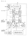
- the input/output apparatus 2 including a UART (Universal Asynchronous Receiver Transmitter) 28a may be used, as shown in Fig. 2 .
- This UART is a device that, for example, converts a serial signal from an external device, such as a personal computer (not shown), into a parallel signal and transfers the parallel signal to the microcomputer 22 and that converts the parallel signal from the microcomputer 22 into a serial signal and transfers the serial signal to the external device.
- a LAN connection unit 28b that is connected a 10Base-T LAN may be used, or as shown in Fig.
- a USB (Universal Serial Bus) connection unit 28c may be provided so as to transmit and receive data to and from an external device.
- a memory card I/F unit 28d may be used. In this case, data is read from a memory card loaded into the memory card I/F unit 28d and is transferred to the microcomputer 12 of the apparatus main body 1, or data from the apparatus main body 1 is recorded in the memory card.
- a PIO (Parallel input/output) 28e may be used so that transmission and reception of data to and from an external device can be performed.
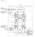
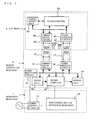
- Fig. 7 is a block diagram illustrating an example of the configuration of a remote control apparatus according to Embodiment 2 of the present invention. Components that are the same as or that correspond to those of Embodiment 1 described with reference to Fig. 1 are designated with the same reference numerals, and descriptions thereof are omitted.
- the remote control apparatus (hereinafter referred to as a "remote controller main body 4") includes a power receiving circuit 41 that is connected through a power-supply line to the power-supply circuit 11 of the apparatus main body 1, which is, for example, an air conditioner, an input unit 42 having various switches (not shown), a microcomputer 43 connected to the functional unit of the apparatus main body 13 of the apparatus main body 1 through a communication line, an output unit 44 having an LED and a liquid-crystal display (not shown), a communication circuit 14 having a transmission and reception unit 15, a power feeding circuit 16 having a feeding unit 17, and an I/F (interface) unit 3.
- a power receiving circuit 41 that is connected through a power-supply line to the power-supply circuit 11 of the apparatus main body 1, which is, for example, an air conditioner, an input unit 42 having various switches (not shown), a microcomputer 43 connected to the functional unit of the apparatus main body 13 of the apparatus main body 1 through a communication line, an output unit 44 having an LED and a liquid-
- the power receiving circuit 41 when the voltage from the power-supply circuit 11 of the apparatus main body 1 is applied, generates a predetermined constant voltage, and supplies it to the input unit 42, the microcomputer 43, the output unit 44, the communication circuit 14, and the power feeding circuit 16.
- the output unit 44 when power is applied, turns on an LED, thereby displaying that the remote controller main body 4 has been powered on.
- the microcomputer 43 will be described in detail when the operation is described.
- the I/F unit 3 includes the microcomputer 22, the communication circuit 24 (communication means) having the transmission and reception unit 25 arranged so as to face the transmission and reception unit 15, the power-supply circuit 26 (power receiving means) having the power receiving unit 27 arranged so as to face the feeding unit 17, and the input/output unit 31 that transfers a signal from an external device (not shown), such as a personal computer, to the microcomputer 22 and transfers a signal from the microcomputer 22 to the external device.
- an external device not shown
- the microcomputer 43 controls the functional unit of the apparatus main body 13 on the basis of the signal from the input unit 42.
- the signal is read, and the current operating state caused by the functional unit of the apparatus main body 13 is displayed on the liquid-crystal display through the output unit 44.
- the power-supply circuit 26 of the I/F unit 3 When an AC voltage is generated in the coil L2 of the power receiving unit 27 of the I/F unit 3 by the induction of the AC magnetic field, the power-supply circuit 26 of the I/F unit 3 generates a predetermined constant voltage on the basis of the AC voltage of the power receiving unit 27, and supplies it to the microcomputer 22, the communication circuit 24, and the input/output unit 31.
- the microcomputer 43 of the remote controller main body 4 causes the power feeding circuit 16 to operate, and thereafter outputs the data obtained from the functional unit of the apparatus main body 13 to the communication circuit 14 so that the high-frequency signal (carrier signal) is amplitude-shift keyed and a high-frequency magnetic field is generated from the transmission and reception unit 15.
- the communication circuit 24 of the I/F unit 3 smoothes the high-frequency AC voltage of the transmission and reception unit 25 so as to remove the high frequency components, extracts to binarize the data of the functional unit of the apparatus main body 13, and outputs to the microcomputer 22 of the I/F unit 3 through the buffer 141.
- the microcomputer 22 outputs the data from the functional unit of the apparatus main body 13 to the input/output unit 31 in accordance with a predetermined procedure, so that the data is transferred to an external device.
- the power-supply circuit 26 of the I/F unit 3 when an AC voltage is generated in the coil L2 of the power receiving unit 27 by the induction of the AC magnetic field from the feeding unit 17, the power-supply circuit 26 of the I/F unit 3 generates a predetermined constant voltage on the basis of the AC voltage, supplies it to the microcomputer 22, the communication circuit 24 and the input/output unit 31.
- the communication circuit 24 smoothes the high-frequency AC voltage that is generated in the transmission and reception unit 25 by of the induction of the high-frequency magnetic field of the transmission and reception unit 15 to remove the high frequency components, extracts to binarize the data receiving instruction output from the microcomputer 43 of the remote controller main body 4, and outputs it to the microcomputer 22 through the buffer 141.
- the microcomputer 22 of the I/F unit 3 when the data receiving instruction is detected, reads the received data from the input/output unit 31 in accordance with a predetermined procedure, outputs the data to the communication circuit 24, whereby the high-frequency signal is amplitude-shift keyed, and causes a high-frequency magnetic field to be generated from the transmission and reception unit 25.
- the communication circuit 14 of the remote controller main body 4 smoothes the high-frequency AC voltage of the transmission and reception unit 15 so as to remove high frequency components, extracts to binarize the received data from the input/output unit 31, and outputs it to the microcomputer 43 of the remote controller main body 4 through the buffer 141.
- the microcomputer 43 outputs the received data to the functional unit of the apparatus main body 13, and the functional unit of the apparatus main body 13 controls its own state or changes internal parameters on the basis of the received data.
- the power feeding circuit 16 of the remote controller main body 4 is made to operate so as to cause the I/F unit 3 to receive power when the data of the functional unit of the apparatus main body 13 is to be transferred from the input/output unit 31 to the external device or when the data received by the input/output unit 31 is to be passed to the functional unit of the apparatus main body 13, the supply of power to the I/F unit 3 may be performed periodically or constantly, and the microcomputer 22 may be made to access the input/output unit 31 so as to make a determination as to the presence or absence of data, and may transmit and receive in accordance with the content of the data.
- the transmission and reception of data may be performed by using a baseband method, a phase shift keying (PSK) method, a frequency shift keying (FSK) method, a quadrature amplitude modulation (QAM) method, or the like.
- PSK phase shift keying
- FSK frequency shift keying
- QAM quadrature amplitude modulation
- a coil is used for feeding power and for communication use respectively, power feeding may be performed intermittently, communication may be performed at an idle time, and the power-supply frequency itself is modulated using data, so that the coil is shared.
- the microcomputer 43 is used for the remote controller main body 4, a logic such as an FPGA (Field Programmable Gate Array), or other control means may be used.
- the transmission and reception of data may be performed to and from, for example, an external device, such as a personal computer (not shown), by using the UART (Universal Asynchronous Receiver Transmitter) 28a for the input/output unit 31.
- the input/output unit 31 may be the LAN connection unit 28b that is connected to a 10Base-T LAN, or as shown in Fig. 10 , the USB (Universal Serial Bus) connection unit 28c may be provided so as to communicate with an external device.
- USB Universal Serial Bus
- the memory card I/F unit 28d may be used as the input/output unit 31, and as shown in Fig. 12 , the PIO (Parallel input/output) 28e may be used so as to communicate with an external device.
- the I/F unit 3 is insulated from the power supply of the remote controller main body 4, and can be provided in the I/F unit 3 without taking any structural measures.
- Embodiment 3 the transmission and reception of data is performed by using the transmission and reception units 15 and 25 of parallel resonance circuits in which a capacitor and a coil are connected in parallel with each other, in present Embodiment 3, the transmission and reception of data is performed by using light.
- a description will be given with reference to Fig. 13 .
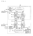
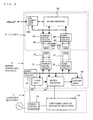
- Fig. 13 is a block diagram illustrating an example of the configuration of a remote control apparatus according to Embodiment 3 of the present invention. Components that are the same as or that correspond to those of Embodiment 2 described with reference to Fig. 7 are designated with the same reference numerals, and descriptions thereof are omitted.
- the communication circuit 32 (communication means) of the I/F unit 3 and the communication circuit 46 of the remote controller main body 4 include, for example, transmission and reception units 33 and 45 formed of a photo-coupler.
- the transmission and reception units 33 and 45 When data is to be transmitted, the transmission and reception units 33 and 45 perform amplitude-shift keying on a high-frequency signal (carrier signal) in accordance with the data, amplifies this data to predetermined electric power, and converts it into light by using a light-emitting diode.
- a high-frequency signal carrier signal
- the transmission and reception units 33 and 45 When data is to be received, light from a light-emitting diode is converted into a signal by using a phototransistor, this signal is smoothed and the high frequency components are removed, and data is extracted, binarized, and output to the microcomputer 22 or 43.
- the microcomputer 43 of the remote controller main body 4 when detecting an instruction of transferring data indicating the operating state of the functional unit of the apparatus main body 13 to an external device through the input unit 42, outputs a data reading instruction to the functional unit of the apparatus main body 13 through a communication line in accordance with the instruction, and when necessary data is input through the communication line in response to the instruction, the microcomputer 43 causes the power feeding circuit 16 (power feeding means) to operate so as to cause the power-supply circuit 26 (power receiving means) of the I/F unit 3 to receive power.
- the data obtained from the functional unit of the apparatus main body 13 is output to the communication circuit 46, the high-frequency signal is amplitude-shift keyed, and light is emitted from the light-emitting diode of the transmission and reception unit 45.
- the communication circuit 32 of the I/F unit 3 smoothes the signal from the transmission and reception unit 33 so as to remove the high frequency components, extracts to binarize the data of the functional unit of the apparatus main body 13, and outputs it to the microcomputer 22 of the I/F unit 3 through the buffer.
- the microcomputer 22 outputs the data from the functional unit of the apparatus main body 13 to the input/output unit 31 in accordance with a predetermined procedure, whereby the data is transferred to the external device.
- the microcomputer 43 of the remote controller main body 4 detects the instruction of transferring the data from the external device to the functional unit of the apparatus main body 13 through the input unit 42, the microcomputer 43 causes the power feeding circuit 16 to operate so as to cause the power-supply circuit 26 of the I/F unit 3 to receive power.
- the microcomputer 43 outputs the data receiving instruction to the communication circuit 46 in accordance with the instruction from the input unit 42 so as to operate, and causes the transmission and reception unit 45 to emit light.
- the communication circuit 32 of the I/F unit 3 smoothes the signal from the transmission and reception unit 33 so as to remove the high frequency components, extracts to binarize the data receiving instruction output from the microcomputer 43 of the remote controller main body 4, and outputs it to the microcomputer 22 of the I/F unit 3 through the buffer.
- the microcomputer 22 detects the data receiving instruction, reads the received data from the input/output unit 31 in accordance with a predetermined procedure, outputs the data to the communication circuit 32 so as to operate, and causes the transmission and reception unit 33 to emit light.
- the phototransistor of the transmission and reception unit 45 of the remote controller main body 4 converts the light into a signal on the basis of the amount of received light
- the communication circuit 46 of the remote controller main body 4 smoothes the signal from the transmission and reception unit 45, removes the high frequency components, extracts to binarize the received data from the input/output unit 31, and outputs it to the microcomputer 43 of the remote controller main body 4 through the buffer.
- the microcomputer 43 outputs the received data to the functional unit of the apparatus main body 13, and the functional unit of the apparatus main body 13 controls its own state or changes an internal parameter on the basis of the received data.
- the transmission and reception of data is performed using the transmission and reception units 45 and 33 formed of a photo-coupler for the communication circuits 46 and 32 of the remote controller main body 4 and the I/F unit 3, respectively. Furthermore, since power is supplied from the power feeding circuit 16 to the power-supply circuit 26 using the feeding unit 17 of a series resonance circuit for the power feeding circuit 16 of the remote controller main body 4 and using the power receiving unit 27 of a parallel resonance circuit for the power-supply circuit 26 of the I/F unit 3, it becomes possible to insulate the I/F unit 3 from the power supply of the remote controller main body 4.
- Embodiment 3 when the data of the functional unit of the apparatus main body 13 is to be transferred from the input/output unit 31 to an external device or when the data received by the input/output unit 31 is passed to the functional unit of the apparatus main body 13, the power feeding circuit 16 of the remote controller main body 4 is operated so that the I/F unit 3 is made to receive power.
- the supply of power to the I/F unit 3 may be performed periodically or constantly, and the microcomputer 22 is made to access the input/output unit 31 so as to make a determination as to the presence or absence of data, and transmission and reception is performed in accordance with the content of the data.
- the transmission of data may be performed by using a baseband method, a phase shift keying (PSK) method, a frequency shift keying (FSK) method, a quadrature amplitude modulation (QAM) method, or the like.
- PSK phase shift keying
- FSK frequency shift keying
- QAM quadrature amplitude modulation
- the microcomputer 43 is used for the remote controller main body 4, a logic, such as an FPGA (Field Programmable Gate Array), and other control means may be used.
- the input/output unit 31 of the I/F unit 3 is not particularly specified, as shown in Fig. 14 , the UART 28a may be used for the input/output unit 31 so that the transmission and reception of data is performed to and from an external device.
- the LAN connection unit 28b that is connected to a 10Base-T LAN may be used or as shown in Fig. 16 , and the USB connection unit 28c may be provided so that communication is performed with an external device.
- the memory card I/F unit 28d may be used as the input/output unit 31, and as shown in Fig.
- the PIO 28e may be used so that the transmission and reception of data to and from an external device can be performed.
- These units can be used because the I/F unit 3 is insulated from the power supply of the remote controller main body 4, and can be provided in the I/F unit 3 without taking any structural measures.
- Application examples of the input/output apparatus of the present invention include an operation display unit of a household electrical appliance and an input/output apparatus of an FA (Factory Automation) apparatus, and application examples of a remote control apparatus include a controller of a building air conditioner.
- FA Vectory Automation
Abstract
Description
- The present invention relates to an input/output apparatus and a remote control apparatus that are equipped with electric apparatuses, such as household electrical appliances and air conditioners.
- Some air conditioners of the related art equip with a wireless remote controller capable of operating (operation, such as driving or stopping) an indoor unit through the wired remote controller instead of a wired remote controller connected through a communication line to an indoor unit. In a case where an indoor unit is operated using one of the two types of remote controllers and thereafter is operated from the other remote controller, the most recent operation is selected with a higher priority (see, for example, Patent Document 1).
-
- [Patent Document 1] Japanese Unexamined Patent Application Publication No.
10-115449 - Since the above-mentioned wired remote controller of an air conditioner of the related art is provided with only reception means for receiving an infrared signal from a wireless remote controller, it is not possible to handle USB memories, which have become popular, or the like. This point is solved by providing an input/output terminal, though. Among air conditioners and household electrical appliances, there are electric apparatuses whose power-supply voltage is 200 V. Therefore, for the purpose of preventing a user from being electrically shocked due to insulation breakdown of the power-supply unit and preventing abnormal electrical current from flowing into an external device through an input/output terminal, it is necessary to have a predetermined required structure so that a user does not touch a metal, such as a terminal, or it is necessary to take measures, such as the insulation of the power-supply unit being reinforced, resulting in the problem that the cost is increased. Furthermore, as for structures whose connection portions such as a USB and a 10BASE-T standard for LAN are defined, structural counter measures cannot be taken in most case, which is a problem.
- The present invention has been achieved to solve problems such as those described above, and has an object to provide an input/output apparatus and a remote control apparatus in which electric shock can be prevented without reinforcing the insulation of a power-supply unit and to which a USB, a LAN, and the like can be connected.
- An input/output apparatus according to the present invention is an input/output apparatus that inputs and outputs a signal to and from an electric apparatus, including: at least one resonance circuit formed of a coil and a capacitor; power receiving means in which electric power obtained from the resonance circuit using electromagnetic induction is made to be a power supply of the present apparatus; and communication means that transmits and receives a signal to and from the electric apparatus by using the resonance circuit. By receiving electric power from the electric apparatus in a non-contact state and by communicating with the electric apparatus in a non-contact state, the input/output apparatus is insulated from a power supply of the electric apparatus.
- Furthermore, a remote control apparatus according to the present invention is a remote control apparatus that operates electric apparatuses through electric wiring and has an internal I/F unit which inputs and outputs a signal to and from the present apparatus. The I/F unit includes input/output means for transmitting and receiving a signal to and from the outside, at least one resonance circuit formed of a coil and a capacitor, power receiving means in which electric power obtained from the resonance circuit using electromagnetic induction is made to be a power supply of the present I/F unit, and communication means for transmitting and receiving a signal to and from the present apparatus by using the resonance circuit. By receiving electric power from the present apparatus in a non-contact state and by communicating with the present apparatus in a non-contact state, the I/F unit is insulated from a power supply of the present apparatus.
- According to the present invention, since the input/output apparatus includes a resonance circuit, power receiving means in which electric power obtained from the resonance circuit using electromagnetic induction is made to be a power supply of the present, and communication means that transmits and receives a signal to and from the electric apparatus by using the resonance circuit, it becomes possible to insulate the input/output apparatus from a power supply of the electric apparatus, thereby removing the need to take measures to reinforce insulation for the power supply. Furthermore, it is possible to prevent a user from being electrically shocked due to the insulation breakdown of the power supply of the electric apparatus, and in addition, since the input/output apparatus is insulated from the electric apparatus in the manner described above, connection of a USB, a LAN, and the like is made possible.
- Furthermore, according to the present invention, since the I/F unit provided in the remote controller main body includes a resonance circuit, power receiving means for using electric power obtained from the resonance circuit by using electromagnetic induction as the power supply of the present I/F unit, and communication means for transmitting and receiving a signal to and from the present apparatus by using the resonance circuit, it becomes possible to insulate the I/F unit from the power supply of the remote control apparatus, thereby removing the need to take measures to reinforce insulation for the power supply. Furthermore, it is possible to prevent the user from being electrically shocked due to insulation breakdown of the power supply of the remote control apparatus, and in addition, the I/F unit is insulated from the remote controller main body in the manner described above, thereby enabling connection of a USB, a LAN, and the like.
-
- [
Fig. 1] Fig. 1 is a block diagram illustrating an example of the configuration of an input/output apparatus according toEmbodiment 1 of the present invention. - [
Fig. 2] Fig. 2 is a block diagram when a UART is used for the input unit and the output unit of the input/output apparatus inEmbodiment 1. - [
Fig. 3] Fig. 3 is a block diagram when a LAN is used for the input unit and the output unit of the input/output apparatus inEmbodiment 1. - [
Fig. 4] Fig. 4 is a block diagram when a USB is used for the input unit and the output unit of the input/output apparatus inEmbodiment 1. - [
Fig. 5] Fig. 5 is a block diagram when a memory card I/F unit is used for the input unit and the output unit of the input/output apparatus inEmbodiment 1. - [
Fig. 6] Fig. 6 is a block diagram when a PIO is used for the input unit and the output unit of the input/output apparatus inEmbodiment 1. - [
Fig. 7] Fig. 7 is a block diagram illustrating an example of the configuration of a remote control apparatus according toEmbodiment 2 of the present invention. - [
Fig. 8] Fig. 8 is a block diagram when a UART is used for an input/output unit of the I/F unit inEmbodiment 2. - [
Fig. 9] Fig. 9 is a block diagram when a LAN is used for the input/output unit of the I/F unit inEmbodiment 2. - [
Fig. 10] Fig. 10 is a block diagram when a USB is used for the input/output unit of the I/F unit inEmbodiment 2. - [
Fig. 11] Fig. 11 is a block diagram when a memory card I/F unit is used for the input/output unit of the I/F unit inEmbodiment 2. - [
Fig. 12] Fig. 12 is a block diagram when a PIO is used for the input/output unit of the I/F unit inEmbodiment 2. - [
Fig. 13] Fig. 13 is a block diagram illustrating an example of the configuration of a remote control apparatus according toEmbodiment 3 of the present invention. - [
Fig. 14] Fig. 14 is a block diagram when a UART is used for the input/output unit of the I/F unit inEmbodiment 3. - [
Fig. 15] Fig. 15 is a block diagram when a LAN is used for the input/output unit of the I/F unit inEmbodiment 3. - [
Fig. 16] Fig. 16 is a block diagram when a USB is used for the input/output unit of the I/F unit inEmbodiment 3. - [
Fig. 17] Fig. 17 is a block diagram when a memory card I/F unit is used for the input/output unit of the I/F unit inEmbodiment 3. - [
Fig. 18] Fig. 18 is a block diagram when a PIO is used for the input/output unit of the I/F unit inEmbodiment 3. - [
Fig. 19] Fig. 19 is a circuit diagram illustrating the configuration of a power feeding circuit of an apparatus main body and a power-supply circuit of an input/output apparatus. - [
Fig. 20] Fig. 20 is a circuit diagram illustrating the configuration of each of communication circuits of the apparatus main body and the input/output apparatus. Reference Numerals - 1 apparatus main body, 11 power-supply circuit, 12 microcomputer, 13 functional unit of apparatus main body, 14 communication circuit, 14a carrier oscillation unit, 14b logical product circuit, 14c amplification circuit, 14d detection circuit, 14e comparator, 141 buffer, 15 transmission and reception unit, 16 power feeding circuit, 16a smoothing circuit, 16b inverter, 17 feeding unit, 2 input/output apparatus, 21 input unit, 22 microcomputer, 23 output unit, 24 communication circuit, 24a carrier oscillation unit, 24b logical product circuit, 24c amplification circuit, 24d detection circuit, 24e comparator, 241 buffer, 25 transmission and reception unit, 26 power-supply circuit, 26a diode, 26b smoothing circuit, 26c power source stabilizing circuit, 26d connector, 27 power receiving unit, 3 I/F unit, 31 input/output unit, 32 communication circuit, 33 transmission and reception unit, 4 remote controller main body, 41 power receiving circuit, 42 input unit, 43 microcomputer, 44 output unit, 45 transmission and reception unit, 46 communication circuit.
-
Fig. 1 is a block diagram illustrating an example of the configuration of an input/output apparatus according toEmbodiment 1 of the present invention.
In the figure, an electric apparatus (hereinafter referred to as an "apparatusmain body 1") of a household electrical appliance, such as, for example, a rice cooker and an electromagnetic cooking device includes a power-supply circuit 11 connected to a commercial power supply, amicrocomputer 12, a functional unit of the apparatusmain body 13, acommunication circuit 14 having a transmission andreception unit 15, apower feeding circuit 16 having afeeding unit 17, and an input/output apparatus 2. When a commercial power supply is applied, the power-supply circuit 11 generates a predetermined constant voltage to supply to themicrocomputer 12, the functional unit of the apparatusmain body 13, thecommunication circuit 14, and thepower feeding circuit 16 respectively. When the power supply is switched on, themicrocomputer 12 causes thepower feeding circuit 16 to operate so as to cause thefeeding unit 17 to generate an AC magnetic field, so that the input/output apparatus 2 side is made to receive an AC voltage. The functional unit of the apparatusmain body 13 is a circuit unit for achieving various functions included in the apparatusmain body 1, and operates under the control of themicrocomputer 12. - The input/
output apparatus 2 includes aninput unit 21 having various operation switches (not shown), amicrocomputer 22, anoutput unit 23 having an LED and a liquid-crystal display (not shown), a communication circuit 24 (communication means) having a transmission andreception unit 25 arranged so as to face the transmission andreception unit 15, and a power-supply circuit 26 (power receiving means) having apower receiving unit 27 arranged so as to face thefeeding unit 17. When an AC voltage is generated in thepower receiving unit 27 due to the induction of an AC magnetic field, the power-supply circuit 26 generates a predetermined constant voltage on the basis of the AC voltage, and supplies it to theinput unit 21, themicrocomputer 22, theoutput unit 23, and thecommunication circuit 24. - Here, a description will be given below, with reference to
Fig. 19 , of the configuration of thepower feeding circuit 16 and the power-supply circuit 26.Fig. 19 is a circuit diagram illustrating the configuration of a power feeding circuit of an apparatus main body and a power-supply circuit of an input/output apparatus.
In the figure, thepower feeding circuit 16 of the apparatusmain body 1 has, at its output end, thefeeding unit 17 of a series resonance circuit in which a capacitor C2 and a coil L1 are connected in series with each other, and includes a smoothing circuit 16a formed of a smoothing capacitor C1 connected between the output ends of the power-supply circuit 11, and a full-bridge type inverter 16b. In thisinverter 16b, switching elements Tr1 and Tr4 are turned on, and switching elements Tr2 and Tr4 are turned off under the control of themicrocomputer 12. Next, the switching elements Tr1 and Tr4 are turned on, the switching elements Tr2 and Tr4 are turned off, and this operation is repeatedly performed at the period of the resonance frequency of the series resonance circuit, and the AC electric current is supplied to thefeeding unit 17, causing the coil L1 of thefeeding unit 17 to generate an AC magnetic field. - The power-
supply circuit 26 of the input/output apparatus 2 has, at its input end, thepower receiving unit 27 of a parallel resonance circuit in which a coil L2 and a capacitor C3 are connected in parallel with each other, and includes adiode 26a for rectifying the AC voltage that is generated by the induction of the AC magnetic field on thefeeding unit 17 side in thepower receiving unit 27, asmoothing circuit 26b formed of a capacitor C4 and a smoothing capacitor C5, a powersource stabilizing circuit 26c formed of a power-supply regulator IC, a capacitor C6, and a smoothing capacitor C7, and aconnector 26d provided at the output end of the powersource stabilizing circuit 26c. The above-mentionedsmoothing circuit 26b smoothes the commercial frequency components of the rectified voltage from thediode 26a by using the capacitor C4 and the smoothing capacitor C5. The powersource stabilizing circuit 26c stabilizes the output voltage of thesmoothing circuit 26b by using a power-supply regulator IC, and suppresses a voltage variation due to a sudden load variation by the capacitor C6 and the smoothing capacitor C7. - The coil L1 of the
feeding unit 17 is separated from the coil L2 of thepower receiving unit 27 by a distance in the range of, for example, several mm to several cm. The spacing is determined by the injection electric power of thepower feeding circuit 16, the electric power consumption on the input/output apparatus 2 side, and adjustment of the configuration (for example, the area of the coils L1 and L2) of thefeeding unit 17 and thepower receiving unit 27. For the coil L1 of thefeeding unit 17 and the coil L2 of thepower receiving unit 27, in general, an air-core coil, an air-core coil in which a magnetic material is arranged on a portion of the end surface thereof or in which a conductor is wound around a ferrite material, or the like is used. Furthermore, in addition to this, a conductor circuit in the form of a flexible sheet, or a sheet-like conductor circuit in which a similar sheet-like magnetic material is arranged on one side thereof may be used. - Next, a description will be given, with reference to
Fig. 20 , of the configuration ofcommunication circuits Fig. 20 is a circuit diagram illustrating the configuration of each of communication circuits of an apparatus main body and an input/output apparatus.
Thecommunication circuit 14 of the apparatusmain body 1 has the transmission andreception unit 15 of a parallel resonance circuit in which a capacitor and a coil are connected in parallel with each other, and includes acarrier oscillation unit 14a for oscillating a high-frequency signal, alogical product circuit 14b for generating the logical product of the high-frequency signal from thecarrier oscillation unit 14a and data from themicrocomputer 12 so as to be subjected to amplitude-shift keying (ASK), anamplification circuit 14c for amplifying the output signal of thelogical product circuit 14b to predetermined electric power so as to excite the transmission andreception unit 15 and for causing a high-frequency magnetic field to be generated from the coil of the transmission andreception unit 15, adetection circuit 14d for smoothing the high-frequencyAC voltage generated in the transmission andreception unit 15 by the induction of the high-frequency magnetic field on the transmission andreception unit 25 side and removing high frequency components, and acomparator 14e for comparing the signal from thedetection circuit 14d with a reference value and outputting the result (binary value) to themicrocomputer 12 through abuffer 141. - Similarly to the above, the
communication circuit 24 of the input/output apparatus 2 has the transmission andreception unit 25 of a parallel resonance circuit in which a capacitor and a coil are connected in parallel to each other, and includes acarrier oscillation unit 24a for oscillating a high-frequency signal, alogical product circuit 24b for generating the logical product of the high-frequency signal from thecarrier oscillation unit 24a and data from themicrocomputer 22 so as to be subjected to amplitude-shift keying (ASK), anamplification circuit 24c for amplifying the output signal of thelogical product circuit 24b to predetermined electric power so as to excite the transmission andreception unit 25 and causing a high-frequency magnetic field to be generated from the coil of the transmission andreception unit 25, adetection circuit 24d for smoothing the high-frequency AC voltage generated in the transmission andreception unit 25 by the induction of the high-frequency magnetic field on the transmission andreception unit 15 side and removing high frequency components, and acomparator 24e for comparing the signal from thedetection circuit 24d with a reference value and outputting the result (binary value) to themicrocomputer 22 through abuffer 241. - Similarly to the above, the coils of the
communication circuits reception units - In the electric apparatus configured as described above, when a commercial power supply is applied to the power-
supply circuit 11 of the apparatusmain body 1, as described above, the power-supply circuit 11 generates a predetermined constant voltage, and supplies it to themicrocomputer 12, the functional unit of the apparatusmain body 13, thecommunication circuit 14, and thepower feeding circuit 16 inside the apparatusmain body 1. When the power supply is switched on, themicrocomputer 12 causes thepower feeding circuit 16 to operate. That is, theinverter 16b of anpower feeding circuit 16 is driven, and an alternating electric current is supplied to thefeeding unit 17 so that the coil L1 is made to generate an AC magnetic field. When an AC voltage is generated in the coil L2 of thepower receiving unit 27 of the input/output apparatus 2 by the induction of the AC magnetic field, the power-supply circuit 26 of the input/output apparatus 2 rectifies the AC voltage from thepower receiving unit 27 so as to smooth the AC voltage, makes the AC voltage be a predetermined constant voltage, and supplies it to theinput unit 21, themicrocomputer 22, theoutput unit 23, and thecommunication circuit 24 inside the input/output apparatus 2, thereby causing them to enter an operable state. At this time, theoutput unit 23 turns on an LED (not shown) so as to indicate that power is being applied. - When a signal based on a switch operation is output to the
microcomputer 22 from theinput unit 21 while power is supplied to the input/output apparatus 2, themicrocomputer 22 outputs data based on the signal from theinput unit 21 to thecommunication circuit 24 so as to be operated. At this time, thecommunication circuit 24 generates the logical product of the high-frequency signal of thecarrier oscillation unit 24a and the data from themicrocomputer 22 so as to be subjected to amplitude-shift keying, amplifies the result, excites the transmission andreception unit 25, and causes a high-frequency magnetic field to be generated from the transmission andreception unit 25. When a high-frequency AC voltage is generated in the transmission andreception unit 15 of the apparatusmain body 1 by the induction of the high-frequency magnetic field, thecommunication circuit 14 of the apparatusmain body 1 smoothes the high-frequencyAC voltage from the transmission andreception unit 15 so as to remove high frequency components, extracts to binarize the data from the input unit 212, and outputs it to themicrocomputer 12 of the apparatusmain body 1 through thebuffer 141. - The
microcomputer 12, when the data from thecommunication circuit 14 is input, controls the functional unit of the apparatusmain body 13 in accordance with the data. When a signal indicating that the operating state has changed is sent from the functional unit of the apparatusmain body 13 under this control, data based on the signal is output to thecommunication circuit 14 so as to be operated, and a high-frequency magnetic field is generated from the transmission andreception unit 15 in the same manner as described above. At this time, the transmission andreception unit 25 of the input/output apparatus 2 generates a high-frequencyAC voltage by way of the induction of the high-frequency magnetic field and outputs the high-frequencyAC voltage to thecommunication circuit 24. Thecommunication circuit 24 smoothes the high-frequency AC voltage so as to remove high frequency components, extracts to binarize the data, and outputs it to themicrocomputer 22 of the input/output apparatus 2 through thebuffer 241. Themicrocomputer 22 outputs the data from the functional unit of the apparatusmain body 13, that is, the changed operating state, as a result of the operation of the functional unit of the apparatusmain body 13 to theoutput unit 23, causing the liquid-crystal display to perform display. - As described above, according to
Embodiment 1, the transmission and reception of data is performed by using the transmission andreception units communication circuits main body 1 and the input/output apparatus 2, respectively. Furthermore, by using thefeeding unit 17 of a series resonance circuit for thepower feeding circuit 16 of the apparatusmain body 1 and by using thepower receiving unit 27 of a parallel resonance circuit for the power-supply circuit 26 of the input/output apparatus 2, electric power is supplied from thepower feeding circuit 16 to the power-supply circuit 26, thereby making it possible to insulate the input/output apparatus 2 from the power supply of the apparatusmain body 1. For this reason, it is not necessary to take measures to reinforce insulation with respect to the power supply, and it is possible to prevent the user from being electrically shocked due to insulation breakdown on the power-supply circuit 11 side of the apparatusmain body 1. - Although
Embodiment 1 describes, as an example, transmission and reception of data in accordance with an amplitude shift keying method to and from thecommunication circuits main body 1 and the input/output apparatus 2, data may be transmitted and received by using a baseband method, a phase shift keying (PSK) method, a frequency shift keying (FSK) method, a quadrature amplitude modulation (QAM) method, or the like. - Furthermore, although coils are used for power supply and for communication use respectively, power is supplied intermittently so that communication may be performed at an idle time, or the power-supply frequency itself is modulated using data so that the coil may be shared. Furthermore, although the
microcomputer 12 is used for the apparatusmain body 1, a logic such as an FPGA (Field Programmable Gate Array), or other control means may be used. - Furthermore, although, in
Embodiment 1, the input/output apparatus 2 including theinput unit 21 and theoutput unit 23 is used as an example, the input/output apparatus 2 including a UART (Universal Asynchronous Receiver Transmitter) 28a may be used, as shown inFig. 2 . This UART is a device that, for example, converts a serial signal from an external device, such as a personal computer (not shown), into a parallel signal and transfers the parallel signal to themicrocomputer 22 and that converts the parallel signal from themicrocomputer 22 into a serial signal and transfers the serial signal to the external device. Furthermore, as shown inFig. 3 , aLAN connection unit 28b that is connected a 10Base-T LAN may be used, or as shown inFig. 4 , a USB (Universal Serial Bus)connection unit 28c may be provided so as to transmit and receive data to and from an external device. Furthermore, as shown inFig. 5 , a memory card I/F unit 28d may be used. In this case, data is read from a memory card loaded into the
memory card I/F unit 28d and is transferred to themicrocomputer 12 of the apparatusmain body 1, or data from the apparatusmain body 1 is recorded in the memory card. Furthermore, as shown inFig. 6 , a PIO (Parallel input/output) 28e may be used so that transmission and reception of data to and from an external device can be performed. These units can be used because the input/output apparatus 2 is insulated from the power supply of the apparatusmain body 1, and can be provided in the input/output apparatus 2 without taking any counter measures structurally. -
Fig. 7 is a block diagram illustrating an example of the configuration of a remote control apparatus according toEmbodiment 2 of the present invention. Components that are the same as or that correspond to those ofEmbodiment 1 described with reference toFig. 1 are designated with the same reference numerals, and descriptions thereof are omitted.
In the figure, the remote control apparatus (hereinafter referred to as a "remote controllermain body 4") includes apower receiving circuit 41 that is connected through a power-supply line to the power-supply circuit 11 of the apparatusmain body 1, which is, for example, an air conditioner, aninput unit 42 having various switches (not shown), amicrocomputer 43 connected to the functional unit of the apparatusmain body 13 of the apparatusmain body 1 through a communication line, anoutput unit 44 having an LED and a liquid-crystal display (not shown), acommunication circuit 14 having a transmission andreception unit 15, apower feeding circuit 16 having a feedingunit 17, and an I/F (interface)unit 3. - The
power receiving circuit 41, when the voltage from the power-supply circuit 11 of the apparatusmain body 1 is applied, generates a predetermined constant voltage, and supplies it to theinput unit 42, themicrocomputer 43, theoutput unit 44, thecommunication circuit 14, and thepower feeding circuit 16. Theoutput unit 44, when power is applied, turns on an LED, thereby displaying that the remote controllermain body 4 has been powered on. Themicrocomputer 43 will be described in detail when the operation is described. The I/F unit 3 includes themicrocomputer 22, the communication circuit 24 (communication means) having the transmission andreception unit 25 arranged so as to face the transmission andreception unit 15, the power-supply circuit 26 (power receiving means) having thepower receiving unit 27 arranged so as to face thefeeding unit 17, and the input/output unit 31 that transfers a signal from an external device (not shown), such as a personal computer, to themicrocomputer 22 and transfers a signal from themicrocomputer 22 to the external device. - In the remote control apparatus configured as described above, for example, when a signal based on a switch operation from the
input unit 42 of the remote controllermain body 4 is output to themicrocomputer 43, themicrocomputer 43 controls the functional unit of the apparatusmain body 13 on the basis of the signal from theinput unit 42. As a result of this control, when a signal indicating the current operating state is input from the functional unit of the apparatusmain body 13, the signal is read, and the current operating state caused by the functional unit of the apparatusmain body 13 is displayed on the liquid-crystal display through theoutput unit 44. - Next, a description will be given of an operation when the operating state of the functional unit of the apparatus
main body 13 is transferred from the input/output unit 31 to the external device on the basis of the operation of the remote controllermain body 4.
When themicrocomputer 43 of the remote controllermain body 4 detects, through theinput unit 42, an instruction of transferring data indicating the operating state of the functional unit of the apparatusmain body 13 to the external device, and then outputs a data reading instruction to the functional unit of the apparatusmain body 13 through a communication line in accordance with the instruction. Then, in response to the instruction when necessary data is input through the communication line, thepower feeding circuit 16 is made to operate, causing the coil L1 of thefeeding unit 17 to generate an AC magnetic field. When an AC voltage is generated in the coil L2 of thepower receiving unit 27 of the I/F unit 3 by the induction of the AC magnetic field, the power-supply circuit 26 of the I/F unit 3 generates a predetermined constant voltage on the basis of the AC voltage of thepower receiving unit 27, and supplies it to themicrocomputer 22, thecommunication circuit 24, and the input/output unit 31. - Furthermore, the
microcomputer 43 of the remote controllermain body 4 causes thepower feeding circuit 16 to operate, and thereafter outputs the data obtained from the functional unit of the apparatusmain body 13 to thecommunication circuit 14 so that the high-frequency signal (carrier signal) is amplitude-shift keyed and a high-frequency magnetic field is generated from the transmission andreception unit 15. When a high-frequencyAC voltage is generated in the transmission andreception unit 25 of the I/F unit 3 by the induction of the high-frequency magnetic field, thecommunication circuit 24 of the I/F unit 3 smoothes the high-frequency AC voltage of the transmission andreception unit 25 so as to remove the high frequency components, extracts to binarize the data of the functional unit of the apparatusmain body 13, and outputs to themicrocomputer 22 of the I/F unit 3 through thebuffer 141. Themicrocomputer 22 outputs the data from the functional unit of the apparatusmain body 13 to the input/output unit 31 in accordance with a predetermined procedure, so that the data is transferred to an external device. - Next, a description will be given of operations when data is input from the input/
output unit 31 to the functional unit of the apparatusmain body 13 on the basis of the operation of the remote controllermain body 4. This operation assumes an operation from the outside, a change of parameters for the operation, or the like.
When themicrocomputer 43 of the remote controllermain body 4 detects, through theinput unit 42, an instruction of transferring data from the external device to the functional unit of the apparatusmain body 13, themicrocomputer 43 causes thepower feeding circuit 16 to operate, so that an AC magnetic field is generated in the coil L1 of thefeeding unit 17. Next, a data receiving instruction is output to thecommunication circuit 14 in accordance with an instruction from theinput unit 42 so as to operate, and a high-frequency magnetic field is generated from the transmission andreception unit 15. - On the other hand, when an AC voltage is generated in the coil L2 of the
power receiving unit 27 by the induction of the AC magnetic field from thefeeding unit 17, the power-supply circuit 26 of the I/F unit 3 generates a predetermined constant voltage on the basis of the AC voltage, supplies it to themicrocomputer 22, thecommunication circuit 24 and the input/output unit 31. At this time, thecommunication circuit 24 smoothes the high-frequency AC voltage that is generated in the transmission andreception unit 25 by of the induction of the high-frequency magnetic field of the transmission andreception unit 15 to remove the high frequency components, extracts to binarize the data receiving instruction output from themicrocomputer 43 of the remote controllermain body 4, and outputs it to themicrocomputer 22 through thebuffer 141. - The
microcomputer 22 of the I/F unit 3, when the data receiving instruction is detected, reads the received data from the input/output unit 31 in accordance with a predetermined procedure, outputs the data to thecommunication circuit 24, whereby the high-frequency signal is amplitude-shift keyed, and causes a high-frequency magnetic field to be generated from the transmission andreception unit 25. When a high-frequencyAC voltage is generated in the transmission andreception unit 15 of the remote controllermain body 4 by the induction of the high-frequency magnetic field, thecommunication circuit 14 of the remote controllermain body 4 smoothes the high-frequency AC voltage of the transmission andreception unit 15 so as to remove high frequency components, extracts to binarize the received data from the input/output unit 31, and outputs it to themicrocomputer 43 of the remote controllermain body 4 through thebuffer 141. Themicrocomputer 43 outputs the received data to the functional unit of the apparatusmain body 13, and the functional unit of the apparatusmain body 13 controls its own state or changes internal parameters on the basis of the received data. - As described above, according to
Embodiment 2, since transmission and reception of data is performed by using the transmission andreception units communication circuits main body 4 and the I/F unit 3, respectively, and furthermore, since power is supplied from thepower feeding circuit 16 to the power-supply circuit 26 by using thefeeding unit 17 of a series resonance circuit for thepower feeding circuit 16 of the remote controllermain body 4 and by using thepower receiving unit 27 of a parallel resonance circuit for the power-supply circuit 26 of the I/F unit 3, it is possible to insulate the I/F unit 3 from the power supply of the remote controllermain body 4. Consequently, it is not necessary to take measures to reinforce insulation with respect to the power supply, and it is possible to suppress the damage of the I/F unit 3 due to insulation breakdown on thepower receiving circuit 41 side of the remote controllermain body 4, and suppress the flow of abnormal electrical current into the external device through the input/output unit 31. - In
Embodiment 2, although thepower feeding circuit 16 of the remote controllermain body 4 is made to operate so as to cause the I/F unit 3 to receive power when the data of the functional unit of the apparatusmain body 13 is to be transferred from the input/output unit 31 to the external device or when the data received by the input/output unit 31 is to be passed to the functional unit of the apparatusmain body 13, the supply of power to the I/F unit 3 may be performed periodically or constantly, and themicrocomputer 22 may be made to access the input/output unit 31 so as to make a determination as to the presence or absence of data, and may transmit and receive in accordance with the content of the data. - Furthermore, although an example in which the
communication circuits main body 4 and the I/F unit 3 transmit and receive data in accordance with an amplitude shift keying method has been described, the transmission and reception of data may be performed by using a baseband method, a phase shift keying (PSK) method, a frequency shift keying (FSK) method, a quadrature amplitude modulation (QAM) method, or the like. - Furthermore, although a coil is used for feeding power and for communication use respectively, power feeding may be performed intermittently, communication may be performed at an idle time, and the power-supply frequency itself is modulated using data, so that the coil is shared. Furthermore, although the
microcomputer 43 is used for the remote controllermain body 4, a logic such as an FPGA (Field Programmable Gate Array), or other control means may be used. - Furthermore, in
Embodiment 2, as shown inFig. 8 , although the input/output unit 31 of the I/F unit 3 is not particularly specified, the transmission and reception of data may be performed to and from, for example, an external device, such as a personal computer (not shown), by using the UART (Universal Asynchronous Receiver Transmitter) 28a for the input/output unit 31. Furthermore, as shown inFig. 9 , the input/output unit 31 may be theLAN connection unit 28b that is connected to a 10Base-T LAN, or as shown inFig. 10 , the USB (Universal Serial Bus)connection unit 28c may be provided so as to communicate with an external device. Furthermore, as shown inFig. 11 , the memory card I/F unit 28d may be used as the input/output unit 31, and as shown inFig. 12 , the PIO (Parallel input/output) 28e may be used so as to communicate with an external device. These units can be used because the I/F unit 3 is insulated from the power supply of the remote controllermain body 4, and can be provided in the I/F unit 3 without taking any structural measures. - Although in
Embodiment 1, the transmission and reception of data is performed by using the transmission andreception units present Embodiment 3, the transmission and reception of data is performed by using light. Hereinafter, a description will be given with reference toFig. 13 . -
Fig. 13 is a block diagram illustrating an example of the configuration of a remote control apparatus according toEmbodiment 3 of the present invention.
Components that are the same as or that correspond to those ofEmbodiment 2 described with reference toFig. 7 are designated with the same reference numerals, and descriptions thereof are omitted.
In the figure, the communication circuit 32 (communication means) of the I/F unit 3 and thecommunication circuit 46 of the remote controllermain body 4 include, for example, transmission andreception units reception units microcomputer - Next, a description will be given of the operation of the remote control apparatus according to
Embodiment 3. Since the operation based on the switch operation of theinput unit 42 of the remote controllermain body 4 is the same as that ofEmbodiment 2, the description thereof is omitted. Furthermore, since the operation of supplying power from the remote controllermain body 4 to the I/F unit 3 when the operating state of the functional unit of the apparatusmain body 13 is transferred from the input/output unit 31 to the external device on the basis of the operation of the remote controllermain body 4, and the operation of supplying power from the remote controllermain body 4 to the I/F unit 3 when data is input from the input/output unit 31 to the functional unit of the apparatusmain body 13 on the basis of the operation of the remote controllermain body 4 are the same as those ofEmbodiment 2, descriptions thereof are omitted. - The
microcomputer 43 of the remote controllermain body 4, when detecting an instruction of transferring data indicating the operating state of the functional unit of the apparatusmain body 13 to an external device through theinput unit 42, outputs a data reading instruction to the functional unit of the apparatusmain body 13 through a communication line in accordance with the instruction, and when necessary data is input through the communication line in response to the instruction, themicrocomputer 43 causes the power feeding circuit 16 (power feeding means) to operate so as to cause the power-supply circuit 26 (power receiving means) of the I/F unit 3 to receive power. Then, the data obtained from the functional unit of the apparatusmain body 13 is output to thecommunication circuit 46, the high-frequency signal is amplitude-shift keyed, and light is emitted from the light-emitting diode of the transmission andreception unit 45. On the other hand, when the phototransistor of the transmission andreception unit 33 of the I/F unit 3 converts the light into a signal in accordance with the amount of received light, thecommunication circuit 32 of the I/F unit 3 smoothes the signal from the transmission andreception unit 33 so as to remove the high frequency components, extracts to binarize the data of the functional unit of the apparatusmain body 13, and outputs it to themicrocomputer 22 of the I/F unit 3 through the buffer. Themicrocomputer 22 outputs the data from the functional unit of the apparatusmain body 13 to the input/output unit 31 in accordance with a predetermined procedure, whereby the data is transferred to the external device. - Furthermore, when the
microcomputer 43 of the remote controllermain body 4 detects the instruction of transferring the data from the external device to the functional unit of the apparatusmain body 13 through theinput unit 42, themicrocomputer 43 causes thepower feeding circuit 16 to operate so as to cause the power-supply circuit 26 of the I/F unit 3 to receive power. Next, themicrocomputer 43 outputs the data receiving instruction to thecommunication circuit 46 in accordance with the instruction from theinput unit 42 so as to operate, and causes the transmission andreception unit 45 to emit light. On the other hand, when the phototransistor of the transmission andreception unit 33 of the I/F unit 3 converts the light into a signal on the basis of the amount of received light, thecommunication circuit 32 of the I/F unit 3 smoothes the signal from the transmission andreception unit 33 so as to remove the high frequency components, extracts to binarize the data receiving instruction output from themicrocomputer 43 of the remote controllermain body 4, and outputs it to themicrocomputer 22 of the I/F unit 3 through the buffer. When themicrocomputer 22 detects the data receiving instruction, reads the received data from the input/output unit 31 in accordance with a predetermined procedure, outputs the data to thecommunication circuit 32 so as to operate, and causes the transmission andreception unit 33 to emit light. At this time, the phototransistor of the transmission andreception unit 45 of the remote controllermain body 4 converts the light into a signal on the basis of the amount of received light, and thecommunication circuit 46 of the remote controllermain body 4 smoothes the signal from the transmission andreception unit 45, removes the high frequency components, extracts to binarize the received data from the input/output unit 31, and outputs it to themicrocomputer 43 of the remote controllermain body 4 through the buffer.
Themicrocomputer 43 outputs the received data to the functional unit of the apparatusmain body 13, and the functional unit of the apparatusmain body 13 controls its own state or changes an internal parameter on the basis of the received data. - As described above, according to
Embodiment 3, the transmission and reception of data is performed using the transmission andreception units communication circuits main body 4 and the I/F unit 3, respectively. Furthermore, since power is supplied from thepower feeding circuit 16 to the power-supply circuit 26 using thefeeding unit 17 of a series resonance circuit for thepower feeding circuit 16 of the remote controllermain body 4 and using thepower receiving unit 27 of a parallel resonance circuit for the power-supply circuit 26 of the I/F unit 3, it becomes possible to insulate the I/F unit 3 from the power supply of the remote controllermain body 4. Consequently, it is not necessary to take measures to reinforce insulation with respect to the power supply, and it is possible to suppress the damage of the I/F unit 3 due to insulation breakdown of thepower receiving circuit 41 of the remote controllermain body 4 and suppress the flow of an abnormal electrical current into an external device through the input/output unit 31. - In
Embodiment 3, when the data of the functional unit of the apparatusmain body 13 is to be transferred from the input/output unit 31 to an external device or when the data received by the input/output unit 31 is passed to the functional unit of the apparatusmain body 13, thepower feeding circuit 16 of the remote controllermain body 4 is operated so that the I/F unit 3 is made to receive power. Alternatively, the supply of power to the I/F unit 3 may be performed periodically or constantly, and themicrocomputer 22 is made to access the input/output unit 31 so as to make a determination as to the presence or absence of data, and transmission and reception is performed in accordance with the content of the data. - Furthermore, although descriptions have been given by taking examples in which the
communication circuits main body 4 and the I/F unit 3 transmit data in accordance with an amplitude shift keying method, the transmission of data may be performed by using a baseband method, a phase shift keying (PSK) method, a frequency shift keying (FSK) method, a quadrature amplitude modulation (QAM) method, or the like. Furthermore, although themicrocomputer 43 is used for the remote controllermain body 4, a logic, such as an FPGA (Field Programmable Gate Array), and other control means may be used. - Furthermore, although in
Embodiment 3, the input/output unit 31 of the I/F unit 3 is not particularly specified, as shown inFig. 14 , theUART 28a may be used for the input/output unit 31 so that the transmission and reception of data is performed to and from an external device. Furthermore, as shown inFig. 15 , theLAN connection unit 28b that is connected to a 10Base-T LAN may be used or as shown inFig. 16 , and theUSB connection unit 28c may be provided so that communication is performed with an external device. Furthermore, as shown inFig. 17 , the memory card I/F unit 28d may be used as the input/output unit 31, and as shown inFig. 18 , thePIO 28e may be used so that the transmission and reception of data to and from an external device can be performed. These units can be used because the I/F unit 3 is insulated from the power supply of the remote controllermain body 4, and can be provided in the I/F unit 3 without taking any structural measures. - Application examples of the input/output apparatus of the present invention include an operation display unit of a household electrical appliance and an input/output apparatus of an FA (Factory Automation) apparatus, and application examples of a remote control apparatus include a controller of a building air conditioner.
Claims (13)
- An input/output apparatus that inputs and outputs a signal to and from an electric apparatus, the input/output apparatus comprising:at least one resonance circuit formed of a coil and a capacitor;power receiving means in which electric power obtained from said resonance circuit using electromagnetic induction is made to be a power supply of the present apparatus; and communication means that transmits and receives a signal to and from the electric apparatus using said resonance circuit,wherein the input/output apparatus is insulated from the power supply of the electric apparatus by receiving electric power from the electric apparatus in a non-contact state and by communicating with the electric apparatus in a non-contact state.
- The input/output apparatus of claim 1, comprising a start-stop synchronous serial communication unit.
- The input/output apparatus of claim 1, comprising a LAN connection unit.
- The input/output apparatus according to Claim 1, comprising a USB connection unit.
- The input/output apparatus of claim 1, comprising a memory card I/F unit.
- The input/output apparatus of claim 1, wherein said input/output apparatus comprises a parallel input/output port.
- A remote control apparatus that operates electric apparatuses through electric wiring and that has an internal I/F unit which inputs and outputs a signal to and from the present apparatus,
wherein said I/F unit includes
input/output means for transmitting and receiving a signal to and from the outside,
at least one resonance circuit formed of a coil and a capacitor,
power receiving means in which electric power obtained from said resonance circuit using electromagnetic induction is made to be a power supply of the present I/F unit, and
communication means for transmitting and receiving a signal to and from the present apparatus using said resonance circuit,
wherein by receiving electric power from the present apparatus in a non-contact state and by communicating with the present apparatus in a non-contact state, said I/F unit is insulated from a power supply of the present apparatus. - A remote control apparatus that operates electric apparatuses through electric wiring and that has an I/F unit that inputs and outputs a signal to and from the present apparatus therein,
wherein said I/F unit includes
input/output means for transmitting and receiving a signal to and from the outside,
at least one resonance circuit formed of a coil and a capacitor,
power receiving means in which electric power obtained from said resonance circuit by using electromagnetic induction is made to be a power supply of the present I/F unit, and
communication means for transmitting and receiving a signal to and from the present apparatus using an optical wireless medium, and
wherein by receiving electric power from the present apparatus in a non-contact state and by communicating with the present apparatus in a non-contact state, said I/F unit is insulated from a power supply of the present apparatus. - The remote control apparatus of claim 7 or 8, wherein said input/output means includes a start-stop synchronous serial communication unit.
- The remote control apparatus of claim 7 or 8, wherein said input/output means includes a LAN connection unit.
- The remote control apparatus of claim 7 or 8, wherein said input/output means includes a USB connection unit.
- The remote control apparatus of claim 7 or 8, wherein said input/output means includes a memory card I/F unit.
- The remote control apparatus of claim 7 or 8, wherein said input/output means includes a parallel input/output port.
Applications Claiming Priority (1)
| Application Number | Priority Date | Filing Date | Title |
|---|---|---|---|
| PCT/JP2009/055102 WO2010106629A1 (en) | 2009-03-17 | 2009-03-17 | Input/output device and remote controller |
Publications (3)
| Publication Number | Publication Date |
|---|---|
| EP2410629A1 true EP2410629A1 (en) | 2012-01-25 |
| EP2410629A4 EP2410629A4 (en) | 2015-09-23 |
| EP2410629B1 EP2410629B1 (en) | 2018-11-28 |
Family
ID=42739300
Family Applications (1)
| Application Number | Title | Priority Date | Filing Date |
|---|---|---|---|
| EP09841835.3A Active EP2410629B1 (en) | 2009-03-17 | 2009-03-17 | Input/output device and remote controller |
Country Status (5)
| Country | Link |
|---|---|
| US (1) | US9306398B2 (en) |
| EP (1) | EP2410629B1 (en) |
| CN (1) | CN102341992B (en) |
| ES (1) | ES2704647T3 (en) |
| WO (1) | WO2010106629A1 (en) |
Families Citing this family (29)
| Publication number | Priority date | Publication date | Assignee | Title |
|---|---|---|---|---|
| US10854378B2 (en) | 2009-02-23 | 2020-12-01 | Triune Ip Llc | Wireless power transmittal |
| US9602167B2 (en) * | 2012-03-28 | 2017-03-21 | Triune Systems, LLC | Remote energy transfer system |
| JP5664019B2 (en) * | 2009-10-28 | 2015-02-04 | Tdk株式会社 | Wireless power feeder, wireless power transmission system, and table and table lamp using the same |
| CN102754306B (en) * | 2010-05-28 | 2014-12-24 | 株式会社村田制作所 | Power transmission system |
| TWI429165B (en) | 2011-02-01 | 2014-03-01 | Fu Da Tong Technology Co Ltd | Method of data transmission in high power |
| US8772977B2 (en) | 2010-08-25 | 2014-07-08 | Tdk Corporation | Wireless power feeder, wireless power transmission system, and table and table lamp using the same |
| US10038338B2 (en) | 2011-02-01 | 2018-07-31 | Fu Da Tong Technology Co., Ltd. | Signal modulation method and signal rectification and modulation device |
| US9075587B2 (en) | 2012-07-03 | 2015-07-07 | Fu Da Tong Technology Co., Ltd. | Induction type power supply system with synchronous rectification control for data transmission |
| US9671444B2 (en) | 2011-02-01 | 2017-06-06 | Fu Da Tong Technology Co., Ltd. | Current signal sensing method for supplying-end module of induction type power supply system |
| US9831687B2 (en) | 2011-02-01 | 2017-11-28 | Fu Da Tong Technology Co., Ltd. | Supplying-end module for induction-type power supply system and signal analysis circuit therein |
| US10056944B2 (en) | 2011-02-01 | 2018-08-21 | Fu Da Tong Technology Co., Ltd. | Data determination method for supplying-end module of induction type power supply system and related supplying-end module |
| US9048881B2 (en) | 2011-06-07 | 2015-06-02 | Fu Da Tong Technology Co., Ltd. | Method of time-synchronized data transmission in induction type power supply system |
| US8941267B2 (en) * | 2011-06-07 | 2015-01-27 | Fu Da Tong Technology Co., Ltd. | High-power induction-type power supply system and its bi-phase decoding method |
| US9600021B2 (en) | 2011-02-01 | 2017-03-21 | Fu Da Tong Technology Co., Ltd. | Operating clock synchronization adjusting method for induction type power supply system |
| US9628147B2 (en) | 2011-02-01 | 2017-04-18 | Fu Da Tong Technology Co., Ltd. | Method of automatically adjusting determination voltage and voltage adjusting device thereof |
| FR2980055B1 (en) * | 2011-09-12 | 2013-12-27 | Valeo Systemes Thermiques | INDUCTIVE POWER TRANSMISSION DEVICE |
| US9246357B2 (en) * | 2011-12-07 | 2016-01-26 | Semiconductor Energy Laboratory Co., Ltd. | Contactless power feeding system |
| JP6008672B2 (en) | 2012-09-26 | 2016-10-19 | ローム株式会社 | Wireless power supply / reception device, wireless power reception device, and wireless power supply device |
| US9787114B2 (en) * | 2014-07-11 | 2017-10-10 | Samsung Electro-Mechanics Co., Ltd. | Wireless power transmitter and wireless power transmission system |
| CN108141191B (en) * | 2015-08-24 | 2021-05-25 | 加利福尼亚大学董事会 | Low power magnetic field body area network |
| US20200091778A1 (en) * | 2018-09-13 | 2020-03-19 | Zyxel Communications Corp. | Wireless transmission system and method thereof for power and data transmission |
| US11476898B2 (en) | 2021-01-28 | 2022-10-18 | Nucurrent, Inc. | Wireless power transfer system with mode switching using selective quality factor alteration |
| US11418069B1 (en) | 2021-01-28 | 2022-08-16 | Nucurrent, Inc. | Wireless power transfer system with data-priority and power-priority transfer modes |
| US11271611B1 (en) * | 2021-01-28 | 2022-03-08 | Nucurrent, Inc. | Wireless power transfer with in-band virtualized wired communications |
| US11316378B1 (en) | 2021-01-28 | 2022-04-26 | Nucurrent, Inc. | Wireless power receiver with in-band virtualized wired communications |
| US11838076B2 (en) | 2021-01-28 | 2023-12-05 | Nucurrent, Inc. | Wireless power transmitter with in-band virtualized wired communications |
| US11483033B2 (en) | 2021-01-28 | 2022-10-25 | Nucurrent, Inc. | Wireless power transfer system with data versus power priority optimization |
| US11754618B2 (en) | 2021-10-15 | 2023-09-12 | Nucurrent, Inc. | Testing device for electronic devices with in-band virtualized wired communications |
| US11626756B1 (en) | 2021-10-15 | 2023-04-11 | Nucurrent, Inc. | Wireless power and data transfer system with out of band communications hand off |
Family Cites Families (19)
| Publication number | Priority date | Publication date | Assignee | Title |
|---|---|---|---|---|
| JPH06187514A (en) | 1992-12-15 | 1994-07-08 | Pfu Ltd | Ic memory card system |
| JPH10115449A (en) | 1996-10-09 | 1998-05-06 | Hitachi Ltd | Wired remote controller for air conditioner |
| US5734254A (en) * | 1996-12-06 | 1998-03-31 | Hewlett-Packard Company | Battery pack and charging system for a portable electronic device |
| US6275143B1 (en) * | 1997-05-09 | 2001-08-14 | Anatoli Stobbe | Security device having wireless energy transmission |
| JP3338631B2 (en) | 1997-05-19 | 2002-10-28 | 日本バルーフ株式会社 | High frequency type remote sensor device |
| JP3884565B2 (en) | 1998-05-21 | 2007-02-21 | 株式会社日立国際電気 | Non-contact IC card reader / writer device |
| JP2001033136A (en) | 1999-07-19 | 2001-02-09 | Sharp Corp | Refrigerator |
| US7295878B1 (en) * | 1999-07-30 | 2007-11-13 | Advanced Bionics Corporation | Implantable devices using rechargeable zero-volt technology lithium-ion batteries |
| JP2001112075A (en) | 1999-10-08 | 2001-04-20 | Mitsubishi Electric Corp | Electric device, power control method for the electric device, and operation command control method for the electric device |
| JP2002198873A (en) | 2000-12-27 | 2002-07-12 | Nippon Baruufu Kk | High-frequency type remote driving apparatus |
| JP2004084976A (en) | 2002-08-23 | 2004-03-18 | Fujitsu General Ltd | Remote control device of air conditioner |
| DE10353943B4 (en) * | 2003-11-18 | 2013-01-03 | Deutsches Zentrum für Luft- und Raumfahrt e.V. | Arrangement for the wireless transmission of energy to an implanted device |
| WO2007007429A1 (en) * | 2005-07-08 | 2007-01-18 | Matsushita Electric Works, Ltd. | Dual wiring system |
| GB2429372B (en) * | 2005-08-16 | 2010-02-24 | Zarlink Semiconductor Ab | A pick up coil functioning as an inductive element and as an antenna, especially useful in high frequency medical in-vivo devices |
| JP4155408B2 (en) * | 2005-09-29 | 2008-09-24 | ソニー・エリクソン・モバイルコミュニケーションズ株式会社 | Charging device and charging system |
| KR100736053B1 (en) * | 2005-10-24 | 2007-07-06 | 삼성전자주식회사 | Apparatus and method of wireless power sharing by induction method |
| JP2007198704A (en) | 2006-01-30 | 2007-08-09 | Matsushita Electric Ind Co Ltd | Air conditioner |
| US7772802B2 (en) * | 2007-03-01 | 2010-08-10 | Eastman Kodak Company | Charging display system |
| JP2008288921A (en) | 2007-05-18 | 2008-11-27 | Funai Electric Co Ltd | Remote control system |
-
2009
- 2009-03-17 EP EP09841835.3A patent/EP2410629B1/en active Active
- 2009-03-17 US US13/145,265 patent/US9306398B2/en active Active
- 2009-03-17 CN CN200980157717.4A patent/CN102341992B/en not_active Expired - Fee Related
- 2009-03-17 ES ES09841835T patent/ES2704647T3/en active Active
- 2009-03-17 WO PCT/JP2009/055102 patent/WO2010106629A1/en active Application Filing
Also Published As
| Publication number | Publication date |
|---|---|
| CN102341992B (en) | 2014-07-09 |
| US20110285212A1 (en) | 2011-11-24 |
| ES2704647T3 (en) | 2019-03-19 |
| EP2410629A4 (en) | 2015-09-23 |
| CN102341992A (en) | 2012-02-01 |
| WO2010106629A1 (en) | 2010-09-23 |
| EP2410629B1 (en) | 2018-11-28 |
| US9306398B2 (en) | 2016-04-05 |
Similar Documents
| Publication | Publication Date | Title |
|---|---|---|
| EP2410629B1 (en) | Input/output device and remote controller | |
| US10530426B2 (en) | Wireless power transferring method and device therefor | |
| KR101743071B1 (en) | Wireless power transmitter,wireless power receiver, and wireless charging system | |
| JP5554937B2 (en) | Contactless power supply system | |
| US9464813B2 (en) | Cooking device | |
| JP4125275B2 (en) | Non-contact IC medium control system | |
| US20180316388A1 (en) | Wireless power transmitter, wireless power receiver, and wireless system, for transmitting and receiving wireless signal, and operating method therefor | |
| KR102034323B1 (en) | Power supply device, power supply method and recording medium | |
| CN108521841A (en) | Support the wireless power transmitter of multiple patterns | |
| US9288663B2 (en) | Terminal device, and communication method and communication module for the same | |
| JP2009165291A (en) | Input/output device, electric equipment, induction heating cooker, and control method of electric equipment and induction heating cooker | |
| US20150180934A1 (en) | System and a method for remotely interacting with items in an electrical field affected environment | |
| JP6918526B2 (en) | Non-contact power transmission equipment and non-contact power transmission equipment | |
| CN110999030B (en) | Wireless charging device, receiver device and related methods | |
| CN112234720B (en) | Contactless power supply device | |
| CN110365127A (en) | Wireless power transmitter/acceptor device | |
| JP2006334208A (en) | Multifunctional processor | |
| KR200453596Y1 (en) | Aquarium and lighting device using wireless power transmission | |
| JP4812738B2 (en) | Remote control device | |
| KR20140094738A (en) | Reception node and transmission node using mutual resonance, power and data reception/transmission system using mutual resonance, method thereof | |
| EP3297124A1 (en) | Wireless power transmission apparatus and control method therefor, method for controlling wireless power reception apparatus, and wireless power transmission system and wireless power transmission method therefor | |
| CN104919814B (en) | Control device and control method | |
| KR102483258B1 (en) | Wireless power transmission apparatus and wireless power transmission method thereof | |
| CN111371130A (en) | Wireless power supply equipment, method and electronic equipment | |
| US9246547B2 (en) | Method and arrangement for transmitting data via an electric conductor of a current network |
Legal Events
| Date | Code | Title | Description |
|---|---|---|---|
| PUAI | Public reference made under article 153(3) epc to a published international application that has entered the european phase |
Free format text: ORIGINAL CODE: 0009012 |
|
| 17P | Request for examination filed |
Effective date: 20110819 |
|
| AK | Designated contracting states |
Kind code of ref document: A1 Designated state(s): AT BE BG CH CY CZ DE DK EE ES FI FR GB GR HR HU IE IS IT LI LT LU LV MC MK MT NL NO PL PT RO SE SI SK TR |
|
| DAX | Request for extension of the european patent (deleted) | ||
| RA4 | Supplementary search report drawn up and despatched (corrected) |
Effective date: 20150825 |
|
| RIC1 | Information provided on ipc code assigned before grant |
Ipc: H02J 17/00 20060101AFI20150819BHEP |
|
| STAA | Information on the status of an ep patent application or granted ep patent |
Free format text: STATUS: EXAMINATION IS IN PROGRESS |
|
| 17Q | First examination report despatched |
Effective date: 20180111 |
|
| REG | Reference to a national code |
Ref country code: DE Ref legal event code: R079 Ref document number: 602009055961 Country of ref document: DE Free format text: PREVIOUS MAIN CLASS: H02J0017000000 Ipc: H02J0050120000 |
|
| GRAP | Despatch of communication of intention to grant a patent |
Free format text: ORIGINAL CODE: EPIDOSNIGR1 |
|
| STAA | Information on the status of an ep patent application or granted ep patent |
Free format text: STATUS: GRANT OF PATENT IS INTENDED |
|
| RIC1 | Information provided on ipc code assigned before grant |
Ipc: H02J 50/12 20160101AFI20180516BHEP |
|
| INTG | Intention to grant announced |
Effective date: 20180612 |
|
| GRAS | Grant fee paid |
Free format text: ORIGINAL CODE: EPIDOSNIGR3 |
|
| GRAA | (expected) grant |
Free format text: ORIGINAL CODE: 0009210 |
|
| STAA | Information on the status of an ep patent application or granted ep patent |
Free format text: STATUS: THE PATENT HAS BEEN GRANTED |
|
| AK | Designated contracting states |
Kind code of ref document: B1 Designated state(s): AT BE BG CH CY CZ DE DK EE ES FI FR GB GR HR HU IE IS IT LI LT LU LV MC MK MT NL NO PL PT RO SE SI SK TR |
|
| REG | Reference to a national code |
Ref country code: GB Ref legal event code: FG4D |
|
| REG | Reference to a national code |
Ref country code: CH Ref legal event code: EP |
|
| REG | Reference to a national code |
Ref country code: AT Ref legal event code: REF Ref document number: 1071382 Country of ref document: AT Kind code of ref document: T Effective date: 20181215 |
|
| REG | Reference to a national code |
Ref country code: DE Ref legal event code: R096 Ref document number: 602009055961 Country of ref document: DE |
|
| REG | Reference to a national code |
Ref country code: IE Ref legal event code: FG4D |
|
| REG | Reference to a national code |
Ref country code: ES Ref legal event code: FG2A Ref document number: 2704647 Country of ref document: ES Kind code of ref document: T3 Effective date: 20190319 |
|
| REG | Reference to a national code |
Ref country code: NL Ref legal event code: MP Effective date: 20181128 |
|
| REG | Reference to a national code |
Ref country code: LT Ref legal event code: MG4D |
|
| REG | Reference to a national code |
Ref country code: AT Ref legal event code: MK05 Ref document number: 1071382 Country of ref document: AT Kind code of ref document: T Effective date: 20181128 |
|
| PG25 | Lapsed in a contracting state [announced via postgrant information from national office to epo] |
Ref country code: BG Free format text: LAPSE BECAUSE OF FAILURE TO SUBMIT A TRANSLATION OF THE DESCRIPTION OR TO PAY THE FEE WITHIN THE PRESCRIBED TIME-LIMIT Effective date: 20190228 Ref country code: IS Free format text: LAPSE BECAUSE OF FAILURE TO SUBMIT A TRANSLATION OF THE DESCRIPTION OR TO PAY THE FEE WITHIN THE PRESCRIBED TIME-LIMIT Effective date: 20190328 Ref country code: LT Free format text: LAPSE BECAUSE OF FAILURE TO SUBMIT A TRANSLATION OF THE DESCRIPTION OR TO PAY THE FEE WITHIN THE PRESCRIBED TIME-LIMIT Effective date: 20181128 Ref country code: FI Free format text: LAPSE BECAUSE OF FAILURE TO SUBMIT A TRANSLATION OF THE DESCRIPTION OR TO PAY THE FEE WITHIN THE PRESCRIBED TIME-LIMIT Effective date: 20181128 Ref country code: LV Free format text: LAPSE BECAUSE OF FAILURE TO SUBMIT A TRANSLATION OF THE DESCRIPTION OR TO PAY THE FEE WITHIN THE PRESCRIBED TIME-LIMIT Effective date: 20181128 Ref country code: HR Free format text: LAPSE BECAUSE OF FAILURE TO SUBMIT A TRANSLATION OF THE DESCRIPTION OR TO PAY THE FEE WITHIN THE PRESCRIBED TIME-LIMIT Effective date: 20181128 Ref country code: AT Free format text: LAPSE BECAUSE OF FAILURE TO SUBMIT A TRANSLATION OF THE DESCRIPTION OR TO PAY THE FEE WITHIN THE PRESCRIBED TIME-LIMIT Effective date: 20181128 Ref country code: NO Free format text: LAPSE BECAUSE OF FAILURE TO SUBMIT A TRANSLATION OF THE DESCRIPTION OR TO PAY THE FEE WITHIN THE PRESCRIBED TIME-LIMIT Effective date: 20190228 |
|
| PG25 | Lapsed in a contracting state [announced via postgrant information from national office to epo] |
Ref country code: GR Free format text: LAPSE BECAUSE OF FAILURE TO SUBMIT A TRANSLATION OF THE DESCRIPTION OR TO PAY THE FEE WITHIN THE PRESCRIBED TIME-LIMIT Effective date: 20190301 Ref country code: PT Free format text: LAPSE BECAUSE OF FAILURE TO SUBMIT A TRANSLATION OF THE DESCRIPTION OR TO PAY THE FEE WITHIN THE PRESCRIBED TIME-LIMIT Effective date: 20190328 Ref country code: SE Free format text: LAPSE BECAUSE OF FAILURE TO SUBMIT A TRANSLATION OF THE DESCRIPTION OR TO PAY THE FEE WITHIN THE PRESCRIBED TIME-LIMIT Effective date: 20181128 |
|
| PG25 | Lapsed in a contracting state [announced via postgrant information from national office to epo] |
Ref country code: NL Free format text: LAPSE BECAUSE OF FAILURE TO SUBMIT A TRANSLATION OF THE DESCRIPTION OR TO PAY THE FEE WITHIN THE PRESCRIBED TIME-LIMIT Effective date: 20181128 |
|
| PG25 | Lapsed in a contracting state [announced via postgrant information from national office to epo] |
Ref country code: CZ Free format text: LAPSE BECAUSE OF FAILURE TO SUBMIT A TRANSLATION OF THE DESCRIPTION OR TO PAY THE FEE WITHIN THE PRESCRIBED TIME-LIMIT Effective date: 20181128 Ref country code: DK Free format text: LAPSE BECAUSE OF FAILURE TO SUBMIT A TRANSLATION OF THE DESCRIPTION OR TO PAY THE FEE WITHIN THE PRESCRIBED TIME-LIMIT Effective date: 20181128 Ref country code: IT Free format text: LAPSE BECAUSE OF FAILURE TO SUBMIT A TRANSLATION OF THE DESCRIPTION OR TO PAY THE FEE WITHIN THE PRESCRIBED TIME-LIMIT Effective date: 20181128 Ref country code: PL Free format text: LAPSE BECAUSE OF FAILURE TO SUBMIT A TRANSLATION OF THE DESCRIPTION OR TO PAY THE FEE WITHIN THE PRESCRIBED TIME-LIMIT Effective date: 20181128 |
|
| REG | Reference to a national code |
Ref country code: DE Ref legal event code: R097 Ref document number: 602009055961 Country of ref document: DE |
|
| PG25 | Lapsed in a contracting state [announced via postgrant information from national office to epo] |
Ref country code: SK Free format text: LAPSE BECAUSE OF FAILURE TO SUBMIT A TRANSLATION OF THE DESCRIPTION OR TO PAY THE FEE WITHIN THE PRESCRIBED TIME-LIMIT Effective date: 20181128 Ref country code: RO Free format text: LAPSE BECAUSE OF FAILURE TO SUBMIT A TRANSLATION OF THE DESCRIPTION OR TO PAY THE FEE WITHIN THE PRESCRIBED TIME-LIMIT Effective date: 20181128 Ref country code: EE Free format text: LAPSE BECAUSE OF FAILURE TO SUBMIT A TRANSLATION OF THE DESCRIPTION OR TO PAY THE FEE WITHIN THE PRESCRIBED TIME-LIMIT Effective date: 20181128 |
|
| PLBE | No opposition filed within time limit |
Free format text: ORIGINAL CODE: 0009261 |
|
| STAA | Information on the status of an ep patent application or granted ep patent |
Free format text: STATUS: NO OPPOSITION FILED WITHIN TIME LIMIT |
|
| PG25 | Lapsed in a contracting state [announced via postgrant information from national office to epo] |
Ref country code: MC Free format text: LAPSE BECAUSE OF FAILURE TO SUBMIT A TRANSLATION OF THE DESCRIPTION OR TO PAY THE FEE WITHIN THE PRESCRIBED TIME-LIMIT Effective date: 20181128 Ref country code: SI Free format text: LAPSE BECAUSE OF FAILURE TO SUBMIT A TRANSLATION OF THE DESCRIPTION OR TO PAY THE FEE WITHIN THE PRESCRIBED TIME-LIMIT Effective date: 20181128 |
|
| REG | Reference to a national code |
Ref country code: CH Ref legal event code: PL |
|
| 26N | No opposition filed |
Effective date: 20190829 |
|
| PG25 | Lapsed in a contracting state [announced via postgrant information from national office to epo] |
Ref country code: LU Free format text: LAPSE BECAUSE OF NON-PAYMENT OF DUE FEES Effective date: 20190317 |
|
| REG | Reference to a national code |
Ref country code: BE Ref legal event code: MM Effective date: 20190331 |
|
| PG25 | Lapsed in a contracting state [announced via postgrant information from national office to epo] |
Ref country code: LI Free format text: LAPSE BECAUSE OF NON-PAYMENT OF DUE FEES Effective date: 20190331 Ref country code: CH Free format text: LAPSE BECAUSE OF NON-PAYMENT OF DUE FEES Effective date: 20190331 Ref country code: IE Free format text: LAPSE BECAUSE OF NON-PAYMENT OF DUE FEES Effective date: 20190317 |
|
| PG25 | Lapsed in a contracting state [announced via postgrant information from national office to epo] |
Ref country code: BE Free format text: LAPSE BECAUSE OF NON-PAYMENT OF DUE FEES Effective date: 20190331 |
|
| PG25 | Lapsed in a contracting state [announced via postgrant information from national office to epo] |
Ref country code: TR Free format text: LAPSE BECAUSE OF FAILURE TO SUBMIT A TRANSLATION OF THE DESCRIPTION OR TO PAY THE FEE WITHIN THE PRESCRIBED TIME-LIMIT Effective date: 20181128 |
|
| PG25 | Lapsed in a contracting state [announced via postgrant information from national office to epo] |
Ref country code: MT Free format text: LAPSE BECAUSE OF NON-PAYMENT OF DUE FEES Effective date: 20190317 |
|
| PG25 | Lapsed in a contracting state [announced via postgrant information from national office to epo] |
Ref country code: CY Free format text: LAPSE BECAUSE OF FAILURE TO SUBMIT A TRANSLATION OF THE DESCRIPTION OR TO PAY THE FEE WITHIN THE PRESCRIBED TIME-LIMIT Effective date: 20181128 |
|
| PG25 | Lapsed in a contracting state [announced via postgrant information from national office to epo] |
Ref country code: HU Free format text: LAPSE BECAUSE OF FAILURE TO SUBMIT A TRANSLATION OF THE DESCRIPTION OR TO PAY THE FEE WITHIN THE PRESCRIBED TIME-LIMIT; INVALID AB INITIO Effective date: 20090317 |
|
| REG | Reference to a national code |
Ref country code: DE Ref legal event code: R084 Ref document number: 602009055961 Country of ref document: DE |
|
| PGFP | Annual fee paid to national office [announced via postgrant information from national office to epo] |
Ref country code: FR Payment date: 20220209 Year of fee payment: 14 |
|
| REG | Reference to a national code |
Ref country code: GB Ref legal event code: 746 Effective date: 20220510 |
|
| PG25 | Lapsed in a contracting state [announced via postgrant information from national office to epo] |
Ref country code: MK Free format text: LAPSE BECAUSE OF FAILURE TO SUBMIT A TRANSLATION OF THE DESCRIPTION OR TO PAY THE FEE WITHIN THE PRESCRIBED TIME-LIMIT Effective date: 20181128 |
|
| PGFP | Annual fee paid to national office [announced via postgrant information from national office to epo] |
Ref country code: ES Payment date: 20220401 Year of fee payment: 14 |
|
| REG | Reference to a national code |
Ref country code: ES Ref legal event code: GC2A Effective date: 20220822 |
|
| PGFP | Annual fee paid to national office [announced via postgrant information from national office to epo] |
Ref country code: GB Payment date: 20230202 Year of fee payment: 15 Ref country code: DE Payment date: 20230131 Year of fee payment: 15 |
|
| P01 | Opt-out of the competence of the unified patent court (upc) registered |
Effective date: 20230512 |
|
| PG25 | Lapsed in a contracting state [announced via postgrant information from national office to epo] |
Ref country code: FR Free format text: LAPSE BECAUSE OF NON-PAYMENT OF DUE FEES Effective date: 20230331 |