EP2410552B1 - Control device for switches with silicone domes - Google Patents
Control device for switches with silicone domes Download PDFInfo
- Publication number
- EP2410552B1 EP2410552B1 EP20110174816 EP11174816A EP2410552B1 EP 2410552 B1 EP2410552 B1 EP 2410552B1 EP 20110174816 EP20110174816 EP 20110174816 EP 11174816 A EP11174816 A EP 11174816A EP 2410552 B1 EP2410552 B1 EP 2410552B1
- Authority
- EP
- European Patent Office
- Prior art keywords
- plate
- silicone
- dome
- metallic
- bubble
- Prior art date
- Legal status (The legal status is an assumption and is not a legal conclusion. Google has not performed a legal analysis and makes no representation as to the accuracy of the status listed.)
- Not-in-force
Links
- 229920001296 polysiloxane Polymers 0.000 title claims description 24
- 238000006243 chemical reaction Methods 0.000 claims description 4
- 230000006835 compression Effects 0.000 claims description 3
- 238000007906 compression Methods 0.000 claims description 3
- 238000009825 accumulation Methods 0.000 claims description 2
- 230000000750 progressive effect Effects 0.000 claims description 2
- XUIMIQQOPSSXEZ-UHFFFAOYSA-N Silicon Chemical compound [Si] XUIMIQQOPSSXEZ-UHFFFAOYSA-N 0.000 claims 1
- 239000012190 activator Substances 0.000 claims 1
- 238000005452 bending Methods 0.000 claims 1
- 229910052710 silicon Inorganic materials 0.000 claims 1
- 239000010703 silicon Substances 0.000 claims 1
- 239000002184 metal Substances 0.000 description 11
- 230000000284 resting effect Effects 0.000 description 3
- 230000007423 decrease Effects 0.000 description 2
- 238000006073 displacement reaction Methods 0.000 description 2
- 230000009286 beneficial effect Effects 0.000 description 1
- 238000004140 cleaning Methods 0.000 description 1
- 230000006837 decompression Effects 0.000 description 1
- 238000010586 diagram Methods 0.000 description 1
- 230000000694 effects Effects 0.000 description 1
- 238000005457 optimization Methods 0.000 description 1
- 230000000717 retained effect Effects 0.000 description 1
Images


Classifications
-
- H—ELECTRICITY
- H01—ELECTRIC ELEMENTS
- H01H—ELECTRIC SWITCHES; RELAYS; SELECTORS; EMERGENCY PROTECTIVE DEVICES
- H01H13/00—Switches having rectilinearly-movable operating part or parts adapted for pushing or pulling in one direction only, e.g. push-button switch
- H01H13/70—Switches having rectilinearly-movable operating part or parts adapted for pushing or pulling in one direction only, e.g. push-button switch having a plurality of operating members associated with different sets of contacts, e.g. keyboard
- H01H13/84—Switches having rectilinearly-movable operating part or parts adapted for pushing or pulling in one direction only, e.g. push-button switch having a plurality of operating members associated with different sets of contacts, e.g. keyboard characterised by ergonomic functions, e.g. for miniature keyboards; characterised by operational sensory functions, e.g. sound feedback
- H01H13/85—Switches having rectilinearly-movable operating part or parts adapted for pushing or pulling in one direction only, e.g. push-button switch having a plurality of operating members associated with different sets of contacts, e.g. keyboard characterised by ergonomic functions, e.g. for miniature keyboards; characterised by operational sensory functions, e.g. sound feedback characterised by tactile feedback features
-
- H—ELECTRICITY
- H01—ELECTRIC ELEMENTS
- H01H—ELECTRIC SWITCHES; RELAYS; SELECTORS; EMERGENCY PROTECTIVE DEVICES
- H01H2201/00—Contacts
- H01H2201/004—Wiping action
-
- H—ELECTRICITY
- H01—ELECTRIC ELEMENTS
- H01H—ELECTRIC SWITCHES; RELAYS; SELECTORS; EMERGENCY PROTECTIVE DEVICES
- H01H2205/00—Movable contacts
- H01H2205/002—Movable contacts fixed to operating part
-
- H—ELECTRICITY
- H01—ELECTRIC ELEMENTS
- H01H—ELECTRIC SWITCHES; RELAYS; SELECTORS; EMERGENCY PROTECTIVE DEVICES
- H01H2209/00—Layers
- H01H2209/068—Properties of the membrane
- H01H2209/074—Properties of the membrane elastomeric
-
- H—ELECTRICITY
- H01—ELECTRIC ELEMENTS
- H01H—ELECTRIC SWITCHES; RELAYS; SELECTORS; EMERGENCY PROTECTIVE DEVICES
- H01H2215/00—Tactile feedback
- H01H2215/004—Collapsible dome or bubble
- H01H2215/018—Collapsible dome or bubble unstressed in open position of switch
-
- H—ELECTRICITY
- H01—ELECTRIC ELEMENTS
- H01H—ELECTRIC SWITCHES; RELAYS; SELECTORS; EMERGENCY PROTECTIVE DEVICES
- H01H2221/00—Actuators
- H01H2221/072—Stroke amplification
-
- H—ELECTRICITY
- H01—ELECTRIC ELEMENTS
- H01H—ELECTRIC SWITCHES; RELAYS; SELECTORS; EMERGENCY PROTECTIVE DEVICES
- H01H2237/00—Mechanism between key and laykey
- H01H2237/004—Cantilever
Definitions
- Subject of the invention is a control device for switches with silicone domes.
- the device which will be described below has been studied in order to realize a family of switches with such an actuating and closing system of the contact, such to obtain force/stroke features suitable for the new demands of the market, by at the same time optimizing the electric performances.
- the aim of the new device is also to exploit some features of the silicone bubbles and others of the metal sheets in order to obtain a new result in terms of feeling without for this reason having to add components or degrade the electric aspects of the switch.
- the invention proposes to realize a control device according to claim 1.
- Figures 1 , 8 and 9 show the main components of a switch provided with an actuation switch according to the invention, comprising vertical actuators 10, flexible actuation plates (also referred to as blades, levers, sheets) 11, a silicone mat 12 provided with bubbles or domes 13 and a printed circuit 14 with paths 15 for realizing a wiring diagram.
- vertical actuators 10 flexible actuation plates (also referred to as blades, levers, sheets) 11, a silicone mat 12 provided with bubbles or domes 13 and a printed circuit 14 with paths 15 for realizing a wiring diagram.
- each bubble or silicone dome 13 occurs by means of an elastic lever (sheet) 11 resting at respective ends 16 and 17 on bubble 13 and plate 14 of circuit 15, passing through an elongated hole 18 of silicone mat 12.
- Figures 2 and 3 show that in a traditional way the electric contact 19 can respectively be either integral with the dome itself or with a metal sheet 20 placed on the underlying circuit.
- the electric contact can be integrally made by metal sheet 11 partially cut in order to form an appendix 21 turning inside bubble or dome 13 through one of its through holes 22.
- Bent contact element 21 of the sheet (a single piece sheet-contact) is so positioned at a predetermined distance from the circuit.
- a protrusion 9 protrudes, which enters elongated hole 8 of sheet 11, obtained by cutting and turning bent appendix 21.
- the protrusion hinders side movements of sheet 11 with respect to bubble 13; in effect, it is important that the sheet be retained in order not to move laterally, avoiding the risk of distorting the contacts or in the case of important movements, of deactivating the switch.
- a centering system is applied to actuator 10, by making it stuck into a hole 23 of the sheet 11 in an intermediate position with its two supports, in order to create the dragging.
- Printed circuit 15 acts both as a support and as an electric connection element between the outlet connector and sheet 11.
- Actuator 10 in its movement downwards pushes on sheet 11 causing both the progressive compression of silicone bubble 13 and the arching of the metal sheet (realized with a flexible geometry). This warping is equivalent to an energy accumulation which will thereafter be a fundamental element during the operation of the device.
- the trend of the effort in relation to the displacement of actuator 10 is therefore defined both by the characteristic curve of the silicone bubble (which notoriously has a first length of stroke in which the force grows and a second length in which the same decreases, all with a trend similar to a sinusoid), and by the elastic feature of the metal sheet.
- the return to the resting position of the whole system occurs with inverted modes; after a first short length in which the force decreases due to the decompression of all intermediate elements brought in compression and during which the user can possibly be able to slowly accompany the system, the system then arrives to the region of the characteristic curve of the silicone bubble in which a steep spike occurs of the reaction force of the same, and due to the flexibility of the sheet, the return movement of the bubble is absorbed by the sheet itself, so causing on the actuator the same abrupt variation of the force described at the beginning. From here on, the return of the actuator occurs with practically linear force/stroke trends up to the exhaustion of the elastic energy stored by the various elements.
- the entire system described can be adopted both individually on switches of the "Push” kind (that is, those having a movement of the user interface element of the vertical kind), and in pairs on switches of the "tilting” kind (that is, having a movement of the user interface element of the rotary kind in two directions).
- the device described before has the peculiarity of allowing a wide range of calibration and refinement of the final result from the point of view of the feeling.
- the greater or smaller rapidity of descent of the curve in the snap phase is easily controlled and defined by putting in relation the intrinsic flexibility of the metal sheet with the own slope of the used bubble.
Landscapes
- Tumbler Switches (AREA)
- Push-Button Switches (AREA)
Description
- Subject of the invention is a control device for switches with silicone domes.
- Document
US 2002/0027062 discloses a device according to the preamble ofclaim 1. - In the automotive, until today the most on board used systems of switches can be summarized by the following types:
- switches with fast-snap metal sheets;
- switches with silicone bubbles with on-board contact;
- switches with silicone bubbles and metal contact integral with the electronic circuit;
- switches with metal snap domes (directly actuated or through silicone intermediary).
- These different types of principles of operation have precise intrinsic features both at the mechanic level (forces, strokes and noise) and at the electric level, so that they do not in some cases satisfy the new demands of the automotive world.
- The device which will be described below has been studied in order to realize a family of switches with such an actuating and closing system of the contact, such to obtain force/stroke features suitable for the new demands of the market, by at the same time optimizing the electric performances.
- At the same time a switch is realized with IP52 protection with the same element (silicone mat) used for generating the feeling of actuation.
- The aim of the new device is also to exploit some features of the silicone bubbles and others of the metal sheets in order to obtain a new result in terms of feeling without for this reason having to add components or degrade the electric aspects of the switch.
- For these and further aims which will be better comprised hereafter, the invention proposes to realize a control device according to
claim 1. - The device of the invention will now be described, with reference to the annexed drawings, in which:
-
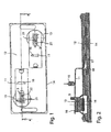
figure 1 is a top view of a switch according to the invention; -
figure 2 shows the A-A cross-section offigure 1 in a first embodiment of the device according to the invention; -
figure 3 shows the A-A cross-section offigure 1 in a second embodiment of the device according to the invention; -
figure 4 shows the A-A cross-section offigure 1 in a third embodiment of the device according to the invention; -
figures 5, 6 and7 show the A-A cross-section offigure 1 in a first embodiment of the device according to the invention and in three different operating positions; -
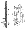
figures 8 and9 are a perspective and exploded view of the switch according to the invention, respectively; -
figure 10 is the A-A cross-section offigure 1 showing the general principle of the device according to the invention. -
Figures 1 ,8 and9 show the main components of a switch provided with an actuation switch according to the invention, comprisingvertical actuators 10, flexible actuation plates (also referred to as blades, levers, sheets) 11, asilicone mat 12 provided with bubbles ordomes 13 and a printedcircuit 14 withpaths 15 for realizing a wiring diagram. - The device according to the invention is shown in its general shape in
figure 10 where it can be noted that the actuation of each bubble orsilicone dome 13 occurs by means of an elastic lever (sheet) 11 resting atrespective ends bubble 13 andplate 14 ofcircuit 15, passing through anelongated hole 18 ofsilicone mat 12. - Obviously, in order to work the system so configured needs an electric contact actuated by the bubble on the circuit.
-
Figures 2 and3 show that in a traditional way theelectric contact 19 can respectively be either integral with the dome itself or with ametal sheet 20 placed on the underlying circuit. - On the contrary, according to the invention, the electric contact can be integrally made by
metal sheet 11 partially cut in order to form anappendix 21 turning inside bubble or dome 13 through one of its throughholes 22.Bent contact element 21 of the sheet (a single piece sheet-contact) is so positioned at a predetermined distance from the circuit. - According to the invention, from each bubble 13 a
protrusion 9 protrudes, which enterselongated hole 8 ofsheet 11, obtained by cutting and turningbent appendix 21. The protrusion hinders side movements ofsheet 11 with respect tobubble 13; in effect, it is important that the sheet be retained in order not to move laterally, avoiding the risk of distorting the contacts or in the case of important movements, of deactivating the switch. - Always according to the invention, a centering system is applied to
actuator 10, by making it stuck into ahole 23 of thesheet 11 in an intermediate position with its two supports, in order to create the dragging. - Printed
circuit 15 acts both as a support and as an electric connection element between the outlet connector andsheet 11. -
Actuator 10 in its movement downwards pushes onsheet 11 causing both the progressive compression ofsilicone bubble 13 and the arching of the metal sheet (realized with a flexible geometry). This warping is equivalent to an energy accumulation which will thereafter be a fundamental element during the operation of the device. - The trend of the effort in relation to the displacement of
actuator 10 is therefore defined both by the characteristic curve of the silicone bubble (which notoriously has a first length of stroke in which the force grows and a second length in which the same decreases, all with a trend similar to a sinusoid), and by the elastic feature of the metal sheet. - When the device has brought the silicone bubble in the stroke conditions which correspond to the maximum effort before collapsing (see
figure 6 ) and consequently the sheet has its maximum warping, the reaction of the bubble begins to reduce itself and consequently the sheet gives back (almost instantly) the stored energy bringing the bubble itself up to the limit of stroke (seefigure 7 ). - This behavior means on the graph force-displacement the postponement of the snap point (point of collapse of the bubble), but most of all in an abrupt switching from the maximum to the minimum reaction of the bubble (feature required by the automotive).
- When contact 21 of the sheet comes in contact with the circuit, the stop of the stroke of the bubble occurs and the contact is closed.
- The further stroke of the actuator is absorbed once again by the flexible metal sheet without damages. This "extra-stroke" has, for this kind of device, a great importance. In fact, following the particular geometry of the sheet itself, the extra-stroke causes a beneficial creep of the two
resting regions sheet 11 oncircuit 15 with a consequent neverending cleaning of the surfaces interested and therefore of the keeping of the electric switching features, similar to those of the new device. - The return to the resting position of the whole system occurs with inverted modes; after a first short length in which the force decreases due to the decompression of all intermediate elements brought in compression and during which the user can possibly be able to slowly accompany the system, the system then arrives to the region of the characteristic curve of the silicone bubble in which a steep spike occurs of the reaction force of the same, and due to the flexibility of the sheet, the return movement of the bubble is absorbed by the sheet itself, so causing on the actuator the same abrupt variation of the force described at the beginning. From here on, the return of the actuator occurs with practically linear force/stroke trends up to the exhaustion of the elastic energy stored by the various elements.
- The entire system described can be adopted both individually on switches of the "Push" kind (that is, those having a movement of the user interface element of the vertical kind), and in pairs on switches of the "tilting" kind (that is, having a movement of the user interface element of the rotary kind in two directions).
- The device described before has the peculiarity of allowing a wide range of calibration and refinement of the final result from the point of view of the feeling.
- In fact, the variation of geometry and position of the various elements involved entails that the obtained forces and strokes are practically endless.
- Furthermore, the greater or smaller rapidity of descent of the curve in the snap phase is easily controlled and defined by putting in relation the intrinsic flexibility of the metal sheet with the own slope of the used bubble.
- The use of the metal lever even for closing the contact allows an undoubted economic efficiency and an electric optimization which makes it possible to use the device even for critical electric applications (minimum currents).
Claims (7)
- Control device having switches with silicone domes, comprising actuator means (10) which act on the silicone domes (13) associated with metallic means for closing and selectively opening electric contacts of a printed circuit activators; whereby
between each actuator means (10) and the respective silicone dome (13) is positioned a plate (11), which rests one side on the dome (13) and upon which said actuator means act, and whereby
the actuation of each bubble or silicone dome (13) occurs by means of an elastic lever, realized by said plate (11) which is flexible, and whereby the actuator means (10) in its movement downwards pushes on said flexible plate (11) causing both the progressive compression of silicone dome (13) and the arching of said flexible plate (11); the arching of the flexible plate (11) is an energy accumulation; characterized in that:
the flexible plate (11) is metallic and has its maximum warping in the stroke condition of the controlling device which correspond to the maximum effort before the collapse of silicone dome (13); and in that the reaction of the silicon dome (13) begins to reduce itself and consequently the metallic flexible plate (11) give backs the stored energy bringing the silicone dome (13) itself up to the limit of stroke. - Device according to claim 1 characterized in that the metallic means (19) for closing and selectively opening electric contacts are plates mounted on the silicone domes (13).
- Device according to claim 1 characterized in that the metallic means (20) for closing and selectively opening electric contacts are plates positioned between the printed circuit (15) and the silicone domes (13).
- Device according to claim 1 characterized in that the metallic means (21) for closing and selectively opening electric contacts are constituted by an appendix (21) or the metallic plate (11) passing through a hole (22) of the silicone dome (13) for acting on the contacts of the circuit itself.
- Device according to claim 1 characterized in that the actuator (10) is fixed in a hole (23) of the plate (11) in a intermediate position with respect to its two supports (17, 21) in such a way as to create the sliding during the actuation and disconnection phase of the switch.
- Device according to claim 4 characterized in that the appendix (21) is obtained by cutting a tract of plate (11) and that the bubble (13) has a protuberance (9) which is inserted in the slot (8) of the plate, obtained by bending the appendix (21), preventing lateral movements of the plate itself (11).
- Device according to claim 1, in which said metallic plate (11) rests one side on the dome (13) and to the other side on the printed circuit (15).
Priority Applications (1)
| Application Number | Priority Date | Filing Date | Title |
|---|---|---|---|
| SI201130329T SI2410552T1 (en) | 2010-07-22 | 2011-07-21 | Control device for switches with silicone domes |
Applications Claiming Priority (1)
| Application Number | Priority Date | Filing Date | Title |
|---|---|---|---|
| ITTO2010A000636A IT1401365B1 (en) | 2010-07-22 | 2010-07-22 | CONTROL DEVICE FOR SWITCHES WITH SILICONE DUOMES |
Publications (2)
| Publication Number | Publication Date |
|---|---|
| EP2410552A1 EP2410552A1 (en) | 2012-01-25 |
| EP2410552B1 true EP2410552B1 (en) | 2014-08-27 |
Family
ID=43629284
Family Applications (1)
| Application Number | Title | Priority Date | Filing Date |
|---|---|---|---|
| EP20110174816 Not-in-force EP2410552B1 (en) | 2010-07-22 | 2011-07-21 | Control device for switches with silicone domes |
Country Status (5)
| Country | Link |
|---|---|
| US (1) | US8872051B2 (en) |
| EP (1) | EP2410552B1 (en) |
| ES (1) | ES2524709T3 (en) |
| IT (1) | IT1401365B1 (en) |
| SI (1) | SI2410552T1 (en) |
Families Citing this family (4)
| Publication number | Priority date | Publication date | Assignee | Title |
|---|---|---|---|---|
| ITTO20121094A1 (en) * | 2012-12-18 | 2014-06-19 | Bitron Spa | CONTROL DEVICE FOR SWITCHES INCLUDING AT LEAST TWO SILICONE DUOMES. |
| ITTO20120749A1 (en) | 2012-08-30 | 2014-03-01 | Bitron Spa | CONTROL DEVICE FOR SWITCHES |
| MX342285B (en) * | 2012-08-30 | 2016-09-23 | Bitron Spa | SWITCH CONTROL DEVICE, WHICH INCLUDES AT LEAST TWO DOMES OF SILICONE. |
| SG11202007327SA (en) * | 2018-02-01 | 2020-08-28 | Razer Asia Pacific Pte Ltd | Key switch mechanisms, user input devices and methods of fabricating a key switch mechanism |
Family Cites Families (6)
| Publication number | Priority date | Publication date | Assignee | Title |
|---|---|---|---|---|
| US3731014A (en) * | 1971-08-02 | 1973-05-01 | Universal Technology | Keyboard switch and unitized multiple switch configuration |
| DE2902769C2 (en) * | 1979-01-25 | 1982-12-09 | Rudolf Schadow Gmbh, 1000 Berlin | Push button switch |
| JPS6230745Y2 (en) * | 1980-04-08 | 1987-08-07 | ||
| JP3941357B2 (en) * | 2000-08-21 | 2007-07-04 | 松下電器産業株式会社 | Pushbutton switch and composite switch using the same |
| JP3996400B2 (en) * | 2002-01-11 | 2007-10-24 | 株式会社東海理化電機製作所 | Elastic sheet structure and printed circuit board structure having electrical conduction function |
| HK1120991A2 (en) * | 2008-02-05 | 2009-04-09 | 佳美工业(香港)有限公司 | Low-profile switch mechanism |
-
2010
- 2010-07-22 IT ITTO2010A000636A patent/IT1401365B1/en active
-
2011
- 2011-07-20 US US13/136,026 patent/US8872051B2/en active Active
- 2011-07-21 ES ES11174816.6T patent/ES2524709T3/en active Active
- 2011-07-21 EP EP20110174816 patent/EP2410552B1/en not_active Not-in-force
- 2011-07-21 SI SI201130329T patent/SI2410552T1/en unknown
Also Published As
| Publication number | Publication date |
|---|---|
| EP2410552A1 (en) | 2012-01-25 |
| IT1401365B1 (en) | 2013-07-18 |
| ITTO20100636A1 (en) | 2012-01-23 |
| ES2524709T3 (en) | 2014-12-11 |
| US20120018292A1 (en) | 2012-01-26 |
| US8872051B2 (en) | 2014-10-28 |
| SI2410552T1 (en) | 2015-02-27 |
Similar Documents
| Publication | Publication Date | Title |
|---|---|---|
| US4467160A (en) | Low profile switch | |
| JP5681282B2 (en) | Switch for electric parking brake in detail | |
| EP2410552B1 (en) | Control device for switches with silicone domes | |
| JP2003263257A (en) | Keyboard input device | |
| JP2005005139A (en) | Switch | |
| CN104685598B (en) | Controls for switches | |
| CN105247644A (en) | Low Travel Switch Assembly | |
| CN101523724A (en) | Operating parts | |
| KR101450995B1 (en) | A module for controlling a force required to actuate an electromechanical actuator | |
| CN101640138A (en) | Touch switch | |
| US6538553B2 (en) | Switching element for electric switch | |
| EP1180775A1 (en) | Keyswitch having a keytop which is movable upward and downward and method of assembling same | |
| JP4779892B2 (en) | Switch and contact module | |
| EP1126483B1 (en) | Switch device | |
| US10886085B2 (en) | Temperature-controlled device for switching off a heating installation | |
| EP1890309B1 (en) | Keyboards | |
| WO2011156888A2 (en) | Electrical switch assembly with pivoting actuator | |
| JP2012528423A (en) | Electrical switch assembly having an angled plunger | |
| CN107978477A (en) | Electric push-button snap switches with means for recognizing the position of the push-button and/or actuating member | |
| WO2014033660A1 (en) | Control device for switches comprising at least two silicone domes | |
| EP2908325A1 (en) | Electric switch with an actuator | |
| JP4730171B2 (en) | Push / Slide switch | |
| JP2010021034A (en) | Push-switch | |
| US20160035515A1 (en) | Single actuator control switch | |
| KR101916284B1 (en) | Switch Having Structure Of Load Peak Position Delay |
Legal Events
| Date | Code | Title | Description |
|---|---|---|---|
| AK | Designated contracting states |
Kind code of ref document: A1 Designated state(s): AL AT BE BG CH CY CZ DE DK EE ES FI FR GB GR HR HU IE IS IT LI LT LU LV MC MK MT NL NO PL PT RO RS SE SI SK SM TR |
|
| AX | Request for extension of the european patent |
Extension state: BA ME |
|
| PUAI | Public reference made under article 153(3) epc to a published international application that has entered the european phase |
Free format text: ORIGINAL CODE: 0009012 |
|
| 17P | Request for examination filed |
Effective date: 20120720 |
|
| 17Q | First examination report despatched |
Effective date: 20130121 |
|
| GRAP | Despatch of communication of intention to grant a patent |
Free format text: ORIGINAL CODE: EPIDOSNIGR1 |
|
| INTG | Intention to grant announced |
Effective date: 20140305 |
|
| RIN1 | Information on inventor provided before grant (corrected) |
Inventor name: TALLONE, FABIO Inventor name: BARILE, MARCO Inventor name: RULFI, UMBERTO Inventor name: BALLATORE, PAOLO |
|
| GRAS | Grant fee paid |
Free format text: ORIGINAL CODE: EPIDOSNIGR3 |
|
| GRAA | (expected) grant |
Free format text: ORIGINAL CODE: 0009210 |
|
| AK | Designated contracting states |
Kind code of ref document: B1 Designated state(s): AL AT BE BG CH CY CZ DE DK EE ES FI FR GB GR HR HU IE IS IT LI LT LU LV MC MK MT NL NO PL PT RO RS SE SI SK SM TR |
|
| REG | Reference to a national code |
Ref country code: GB Ref legal event code: FG4D |
|
| REG | Reference to a national code |
Ref country code: CH Ref legal event code: EP |
|
| REG | Reference to a national code |
Ref country code: AT Ref legal event code: REF Ref document number: 684868 Country of ref document: AT Kind code of ref document: T Effective date: 20140915 |
|
| REG | Reference to a national code |
Ref country code: IE Ref legal event code: FG4D |
|
| REG | Reference to a national code |
Ref country code: DE Ref legal event code: R096 Ref document number: 602011009411 Country of ref document: DE Effective date: 20141009 |
|
| REG | Reference to a national code |
Ref country code: ES Ref legal event code: FG2A Ref document number: 2524709 Country of ref document: ES Kind code of ref document: T3 Effective date: 20141211 |
|
| REG | Reference to a national code |
Ref country code: AT Ref legal event code: MK05 Ref document number: 684868 Country of ref document: AT Kind code of ref document: T Effective date: 20140827 |
|
| REG | Reference to a national code |
Ref country code: LT Ref legal event code: MG4D |
|
| REG | Reference to a national code |
Ref country code: NL Ref legal event code: VDEP Effective date: 20140827 |
|
| PG25 | Lapsed in a contracting state [announced via postgrant information from national office to epo] |
Ref country code: FI Free format text: LAPSE BECAUSE OF FAILURE TO SUBMIT A TRANSLATION OF THE DESCRIPTION OR TO PAY THE FEE WITHIN THE PRESCRIBED TIME-LIMIT Effective date: 20140827 Ref country code: BG Free format text: LAPSE BECAUSE OF FAILURE TO SUBMIT A TRANSLATION OF THE DESCRIPTION OR TO PAY THE FEE WITHIN THE PRESCRIBED TIME-LIMIT Effective date: 20141127 Ref country code: LT Free format text: LAPSE BECAUSE OF FAILURE TO SUBMIT A TRANSLATION OF THE DESCRIPTION OR TO PAY THE FEE WITHIN THE PRESCRIBED TIME-LIMIT Effective date: 20140827 Ref country code: SE Free format text: LAPSE BECAUSE OF FAILURE TO SUBMIT A TRANSLATION OF THE DESCRIPTION OR TO PAY THE FEE WITHIN THE PRESCRIBED TIME-LIMIT Effective date: 20140827 Ref country code: GR Free format text: LAPSE BECAUSE OF FAILURE TO SUBMIT A TRANSLATION OF THE DESCRIPTION OR TO PAY THE FEE WITHIN THE PRESCRIBED TIME-LIMIT Effective date: 20141128 Ref country code: PT Free format text: LAPSE BECAUSE OF FAILURE TO SUBMIT A TRANSLATION OF THE DESCRIPTION OR TO PAY THE FEE WITHIN THE PRESCRIBED TIME-LIMIT Effective date: 20141229 Ref country code: NO Free format text: LAPSE BECAUSE OF FAILURE TO SUBMIT A TRANSLATION OF THE DESCRIPTION OR TO PAY THE FEE WITHIN THE PRESCRIBED TIME-LIMIT Effective date: 20141127 |
|
| PG25 | Lapsed in a contracting state [announced via postgrant information from national office to epo] |
Ref country code: HR Free format text: LAPSE BECAUSE OF FAILURE TO SUBMIT A TRANSLATION OF THE DESCRIPTION OR TO PAY THE FEE WITHIN THE PRESCRIBED TIME-LIMIT Effective date: 20140827 Ref country code: LV Free format text: LAPSE BECAUSE OF FAILURE TO SUBMIT A TRANSLATION OF THE DESCRIPTION OR TO PAY THE FEE WITHIN THE PRESCRIBED TIME-LIMIT Effective date: 20140827 Ref country code: RS Free format text: LAPSE BECAUSE OF FAILURE TO SUBMIT A TRANSLATION OF THE DESCRIPTION OR TO PAY THE FEE WITHIN THE PRESCRIBED TIME-LIMIT Effective date: 20140827 Ref country code: IS Free format text: LAPSE BECAUSE OF FAILURE TO SUBMIT A TRANSLATION OF THE DESCRIPTION OR TO PAY THE FEE WITHIN THE PRESCRIBED TIME-LIMIT Effective date: 20141227 Ref country code: CY Free format text: LAPSE BECAUSE OF FAILURE TO SUBMIT A TRANSLATION OF THE DESCRIPTION OR TO PAY THE FEE WITHIN THE PRESCRIBED TIME-LIMIT Effective date: 20140827 Ref country code: AT Free format text: LAPSE BECAUSE OF FAILURE TO SUBMIT A TRANSLATION OF THE DESCRIPTION OR TO PAY THE FEE WITHIN THE PRESCRIBED TIME-LIMIT Effective date: 20140827 |
|
| PG25 | Lapsed in a contracting state [announced via postgrant information from national office to epo] |
Ref country code: NL Free format text: LAPSE BECAUSE OF FAILURE TO SUBMIT A TRANSLATION OF THE DESCRIPTION OR TO PAY THE FEE WITHIN THE PRESCRIBED TIME-LIMIT Effective date: 20140827 |
|
| PG25 | Lapsed in a contracting state [announced via postgrant information from national office to epo] |
Ref country code: IT Free format text: LAPSE BECAUSE OF FAILURE TO SUBMIT A TRANSLATION OF THE DESCRIPTION OR TO PAY THE FEE WITHIN THE PRESCRIBED TIME-LIMIT Effective date: 20140827 Ref country code: SK Free format text: LAPSE BECAUSE OF FAILURE TO SUBMIT A TRANSLATION OF THE DESCRIPTION OR TO PAY THE FEE WITHIN THE PRESCRIBED TIME-LIMIT Effective date: 20140827 Ref country code: EE Free format text: LAPSE BECAUSE OF FAILURE TO SUBMIT A TRANSLATION OF THE DESCRIPTION OR TO PAY THE FEE WITHIN THE PRESCRIBED TIME-LIMIT Effective date: 20140827 Ref country code: RO Free format text: LAPSE BECAUSE OF FAILURE TO SUBMIT A TRANSLATION OF THE DESCRIPTION OR TO PAY THE FEE WITHIN THE PRESCRIBED TIME-LIMIT Effective date: 20140827 Ref country code: DK Free format text: LAPSE BECAUSE OF FAILURE TO SUBMIT A TRANSLATION OF THE DESCRIPTION OR TO PAY THE FEE WITHIN THE PRESCRIBED TIME-LIMIT Effective date: 20140827 Ref country code: CZ Free format text: LAPSE BECAUSE OF FAILURE TO SUBMIT A TRANSLATION OF THE DESCRIPTION OR TO PAY THE FEE WITHIN THE PRESCRIBED TIME-LIMIT Effective date: 20140827 |
|
| REG | Reference to a national code |
Ref country code: HU Ref legal event code: AG4A Ref document number: E022493 Country of ref document: HU Ref country code: DE Ref legal event code: R097 Ref document number: 602011009411 Country of ref document: DE |
|
| PG25 | Lapsed in a contracting state [announced via postgrant information from national office to epo] |
Ref country code: PL Free format text: LAPSE BECAUSE OF FAILURE TO SUBMIT A TRANSLATION OF THE DESCRIPTION OR TO PAY THE FEE WITHIN THE PRESCRIBED TIME-LIMIT Effective date: 20140827 |
|
| PLBE | No opposition filed within time limit |
Free format text: ORIGINAL CODE: 0009261 |
|
| STAA | Information on the status of an ep patent application or granted ep patent |
Free format text: STATUS: NO OPPOSITION FILED WITHIN TIME LIMIT |
|
| 26N | No opposition filed |
Effective date: 20150528 |
|
| PG25 | Lapsed in a contracting state [announced via postgrant information from national office to epo] |
Ref country code: MC Free format text: LAPSE BECAUSE OF FAILURE TO SUBMIT A TRANSLATION OF THE DESCRIPTION OR TO PAY THE FEE WITHIN THE PRESCRIBED TIME-LIMIT Effective date: 20140827 |
|
| REG | Reference to a national code |
Ref country code: CH Ref legal event code: PL |
|
| GBPC | Gb: european patent ceased through non-payment of renewal fee |
Effective date: 20150721 |
|
| PG25 | Lapsed in a contracting state [announced via postgrant information from national office to epo] |
Ref country code: LU Free format text: LAPSE BECAUSE OF FAILURE TO SUBMIT A TRANSLATION OF THE DESCRIPTION OR TO PAY THE FEE WITHIN THE PRESCRIBED TIME-LIMIT Effective date: 20150721 |
|
| REG | Reference to a national code |
Ref country code: IE Ref legal event code: MM4A |
|
| PG25 | Lapsed in a contracting state [announced via postgrant information from national office to epo] |
Ref country code: GB Free format text: LAPSE BECAUSE OF NON-PAYMENT OF DUE FEES Effective date: 20150721 Ref country code: LI Free format text: LAPSE BECAUSE OF NON-PAYMENT OF DUE FEES Effective date: 20150731 Ref country code: CH Free format text: LAPSE BECAUSE OF NON-PAYMENT OF DUE FEES Effective date: 20150731 |
|
| REG | Reference to a national code |
Ref country code: FR Ref legal event code: ST Effective date: 20160331 |
|
| PG25 | Lapsed in a contracting state [announced via postgrant information from national office to epo] |
Ref country code: FR Free format text: LAPSE BECAUSE OF NON-PAYMENT OF DUE FEES Effective date: 20150731 |
|
| PG25 | Lapsed in a contracting state [announced via postgrant information from national office to epo] |
Ref country code: BE Free format text: LAPSE BECAUSE OF FAILURE TO SUBMIT A TRANSLATION OF THE DESCRIPTION OR TO PAY THE FEE WITHIN THE PRESCRIBED TIME-LIMIT Effective date: 20140827 Ref country code: IE Free format text: LAPSE BECAUSE OF NON-PAYMENT OF DUE FEES Effective date: 20150721 |
|
| PG25 | Lapsed in a contracting state [announced via postgrant information from national office to epo] |
Ref country code: MT Free format text: LAPSE BECAUSE OF FAILURE TO SUBMIT A TRANSLATION OF THE DESCRIPTION OR TO PAY THE FEE WITHIN THE PRESCRIBED TIME-LIMIT Effective date: 20140827 |
|
| PG25 | Lapsed in a contracting state [announced via postgrant information from national office to epo] |
Ref country code: SM Free format text: LAPSE BECAUSE OF FAILURE TO SUBMIT A TRANSLATION OF THE DESCRIPTION OR TO PAY THE FEE WITHIN THE PRESCRIBED TIME-LIMIT Effective date: 20140827 |
|
| PG25 | Lapsed in a contracting state [announced via postgrant information from national office to epo] |
Ref country code: TR Free format text: LAPSE BECAUSE OF FAILURE TO SUBMIT A TRANSLATION OF THE DESCRIPTION OR TO PAY THE FEE WITHIN THE PRESCRIBED TIME-LIMIT Effective date: 20140827 |
|
| PG25 | Lapsed in a contracting state [announced via postgrant information from national office to epo] |
Ref country code: MK Free format text: LAPSE BECAUSE OF FAILURE TO SUBMIT A TRANSLATION OF THE DESCRIPTION OR TO PAY THE FEE WITHIN THE PRESCRIBED TIME-LIMIT Effective date: 20140827 |
|
| PG25 | Lapsed in a contracting state [announced via postgrant information from national office to epo] |
Ref country code: AL Free format text: LAPSE BECAUSE OF FAILURE TO SUBMIT A TRANSLATION OF THE DESCRIPTION OR TO PAY THE FEE WITHIN THE PRESCRIBED TIME-LIMIT Effective date: 20140827 |
|
| PGFP | Annual fee paid to national office [announced via postgrant information from national office to epo] |
Ref country code: ES Payment date: 20190822 Year of fee payment: 9 Ref country code: DE Payment date: 20190730 Year of fee payment: 9 Ref country code: SI Payment date: 20190712 Year of fee payment: 9 |
|
| PGFP | Annual fee paid to national office [announced via postgrant information from national office to epo] |
Ref country code: HU Payment date: 20190709 Year of fee payment: 9 |
|
| REG | Reference to a national code |
Ref country code: DE Ref legal event code: R119 Ref document number: 602011009411 Country of ref document: DE |
|
| PG25 | Lapsed in a contracting state [announced via postgrant information from national office to epo] |
Ref country code: HU Free format text: LAPSE BECAUSE OF NON-PAYMENT OF DUE FEES Effective date: 20200722 |
|
| PG25 | Lapsed in a contracting state [announced via postgrant information from national office to epo] |
Ref country code: DE Free format text: LAPSE BECAUSE OF NON-PAYMENT OF DUE FEES Effective date: 20210202 Ref country code: SI Free format text: LAPSE BECAUSE OF NON-PAYMENT OF DUE FEES Effective date: 20200722 |
|
| REG | Reference to a national code |
Ref country code: ES Ref legal event code: FD2A Effective date: 20211230 |
|
| PG25 | Lapsed in a contracting state [announced via postgrant information from national office to epo] |
Ref country code: ES Free format text: LAPSE BECAUSE OF NON-PAYMENT OF DUE FEES Effective date: 20200722 |