EP2410342A2 - Pipetting device with independently movable pipette tips - Google Patents
Pipetting device with independently movable pipette tips Download PDFInfo
- Publication number
- EP2410342A2 EP2410342A2 EP11171558A EP11171558A EP2410342A2 EP 2410342 A2 EP2410342 A2 EP 2410342A2 EP 11171558 A EP11171558 A EP 11171558A EP 11171558 A EP11171558 A EP 11171558A EP 2410342 A2 EP2410342 A2 EP 2410342A2
- Authority
- EP
- European Patent Office
- Prior art keywords
- vessels
- units
- pipetting
- pipette
- distance
- Prior art date
- Legal status (The legal status is an assumption and is not a legal conclusion. Google has not performed a legal analysis and makes no representation as to the accuracy of the status listed.)
- Granted
Links
Images


Classifications
-
- G—PHYSICS
- G01—MEASURING; TESTING
- G01N—INVESTIGATING OR ANALYSING MATERIALS BY DETERMINING THEIR CHEMICAL OR PHYSICAL PROPERTIES
- G01N35/00—Automatic analysis not limited to methods or materials provided for in any single one of groups G01N1/00 - G01N33/00; Handling materials therefor
- G01N35/10—Devices for transferring samples or any liquids to, in, or from, the analysis apparatus, e.g. suction devices, injection devices
- G01N35/1009—Characterised by arrangements for controlling the aspiration or dispense of liquids
- G01N35/1011—Control of the position or alignment of the transfer device
-
- B—PERFORMING OPERATIONS; TRANSPORTING
- B01—PHYSICAL OR CHEMICAL PROCESSES OR APPARATUS IN GENERAL
- B01L—CHEMICAL OR PHYSICAL LABORATORY APPARATUS FOR GENERAL USE
- B01L3/00—Containers or dishes for laboratory use, e.g. laboratory glassware; Droppers
- B01L3/02—Burettes; Pipettes
- B01L3/021—Pipettes, i.e. with only one conduit for withdrawing and redistributing liquids
-
- G—PHYSICS
- G01—MEASURING; TESTING
- G01N—INVESTIGATING OR ANALYSING MATERIALS BY DETERMINING THEIR CHEMICAL OR PHYSICAL PROPERTIES
- G01N35/00—Automatic analysis not limited to methods or materials provided for in any single one of groups G01N1/00 - G01N33/00; Handling materials therefor
- G01N35/10—Devices for transferring samples or any liquids to, in, or from, the analysis apparatus, e.g. suction devices, injection devices
- G01N35/1009—Characterised by arrangements for controlling the aspiration or dispense of liquids
- G01N35/1016—Control of the volume dispensed or introduced
-
- G—PHYSICS
- G01—MEASURING; TESTING
- G01N—INVESTIGATING OR ANALYSING MATERIALS BY DETERMINING THEIR CHEMICAL OR PHYSICAL PROPERTIES
- G01N35/00—Automatic analysis not limited to methods or materials provided for in any single one of groups G01N1/00 - G01N33/00; Handling materials therefor
- G01N35/10—Devices for transferring samples or any liquids to, in, or from, the analysis apparatus, e.g. suction devices, injection devices
- G01N35/1065—Multiple transfer devices
- G01N35/1067—Multiple transfer devices for transfer to or from containers having different spacing
Definitions
- the present invention relates to a pipetting device, method and system with more than one pipetting units, wherein said pipetting units are are movable relative to each other along one axis.
- Pipetting devices are used in automated analyzers for distributing samples or reagents. Pipetting devices comprising more than one pipetting unit are known in the art. Movable pipetting units are useful to transfer samples or reagents from one number of vessels to another number of vessels. Such a device with movable pipetting units is known from US2001/0036425 .
- the present invention provides an improved device with movable pipetting units.
- the present invention relates to a device for aspirating and dispensing more than one liquid sample.
- the invention also relates to an analyzer comprising such a device.
- the device comprises a main frame body and more than one pipetting units, said pipetting units extending side by side in parallel with each other.
- a pipetting unit comprises an interface for interacting with an interface of a pipette tip.
- It further comprises a first module for aspirating and dispensing a liquid.
- One preferred embodiment of such a module is a pump.
- It further comprises a second module for Y-axis movement, and third module for Z-axis movement, wherein said second and third modules function independently.
- Said second and third modules are preferably actuators. More preferably, said third module is a spindle drive.
- Said pipette unit further comprises a fourth module for controlling functions of said pipette unit.
- said fourth module is an electronic module controlling all functions of said pipette unit.
- the pipetting unit comprises two frames for receiving at least one of said modules, wherein said at least one module is mounted in one of said frames.
- the device comprises an X-transfer mechanism connected to said main frame body to which said pipetting units are connected. Said at least one module of one pipette unit is mounted in one of said two frames, and said at least one module of the adjacent pipette units are mounted in the frame in the location corresponding to the frame of said first pipette unit which is empty.
- the device according to the present invention has the advantage that an appropriate spacing between pipette units can be achieved even if modules required for each pipette unit are too broad to be placed next to each other.
- At least one module is mounted outside of said frame, wherein the said modules of two adjacent pipetting units are staggered. This again allows achieving an appropriate spacing between said pipetting units.
- the pipetting unit does not comprise frames.
- at least one module is mounted in a staggered fashion on two adjacent pipetting units.
- a preferred shortest distance between said more than one pipette units is 10 mm or shorter. More preferably, the shortest distance between said more than one pipette units is between 10 mm and 1 mm. Further preferred shortest distances are 9 mm, 4.5 mm, 2.25 mm, 1.125 mm.
- the device hereinbefore described additionally comprises a sixth module, which is a sensor module.
- Preferred sensor modules are sensors for initializing or determining the position in Y or Z direction of the pipette unit.
- Preferred sensors for determining the position of the pipette unit in is a ultrasound sensor.
- one side of a pipette unit is connected to said Y-axis transfer mechanism.
- said pipette units additionally comprise ball bearings, wherein said ball bearings of two adjacent pipette units are staggered.
- the present invention further relates to a method of pipetting samples from a first set of vessels holding said samples to a second set of vessels, wherein the distance between adjacent vessels of the first set of vessels is different from the distance between adjacent vessels of the second set of vessels.
- Said method comprises aspirating said samples with pipette tips mounted on a device hereinbefore described, wherein the distance between said pipetting units is adjusted to the distance between said first set of vessels by moving the pipetting units along one axis prior to aspiration. The distance between the pipette units to the distance between said second set of vessels prior to dispensing is then adjusted for dispensing said samples into the second set of vessels.
- said first set of vessels comprises at least two vessels in a linear arrangement.
- said second set of vessels are integrally formed.
- the second set of vessels is only one vessel.
- said second set of vessels comprises a multiwell plate.
- the present invention further relates to a method of isolating and analyzing at least one analyte that may be present in at least one liquid sample in an automated analytical system, comprising the automated steps of providing a first set of vessels comprising said at least one liquid sample to said automated analytical system; aspirating at least a portion of said at least two liquid samples from said first set of vessels with a pipetting device comprising more than one pipetting unit, wherein the distance between said pipetting units is adjusted to the distance between the first set of vessels prior to aspiration; adjusting the distance between said pipetting units to the distance between vessels of a second set of vessels; dispensing said liquid samples into said second set of vessels.
- the method further comprises the steps of combining together a solid support material and one of said fluid samples in a well of said second set of vessels vessel for a period of time and under conditions sufficient to permit said analyte to be immobilized on the solid support material. isolating the solid support material is then isolated from other material present in the fluid sample in a separation station. The analyte is then purified in the separation station by separating the fluid sample from the solid support material and washing the materials one or more times with a wash buffer. Finally, the analyte is analyzed.
- the method comprises at least two liquid samples.
- said analyte is a nucleic acid. More preferably, said device comprises the device hereinbefore described.
- the present invention also relates to an analytical system for isolating an analyte, comprising a module for transferring samples from a first set of vessels to a second set of vessels, wherein said module comprises a pipetting device comprising more than one pipetting units, wherein said pipetting units are movable relative to each other along one axis; and a module for isolating said analyte.
- said analytical system additionally comprises a module for analyzing said analyte.
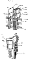
- a device (700) according to the invention comprising a main frame body (701) and two pipetting units (702 a,b) is shown in Fig. 1 .
- Each pipetting unit (702) comprises two frames (703, 704).
- any one of the pipetting unit (702) comprises an electronic module (705).
- the electronic module (705) of pipetting unit (702 a) is mounted in the lower frame (703)
- the electronic module (705) of pipetting unit (702 b) is mounted in the upper frame (704).
- the Y-axis actuators (717) are also mounted on the pipette units in a staggered fashion.
- the pipetting units also comprise interfaces (706) for interacting with pipette tips (3, 4).
- Fig. 2 shows the two units (702 a, b) as they are moved together, bringing the two pipette tips (3, 4) into close proximity.
- Corresponding modules (eg 705) are arranged in an nonoverlapping way to allow for an optimal spacing between the two pipetting units.
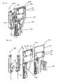
- Fig. 3 a) shows a device (700) with five pipette units (702 a to e) with the staggered mount of different modules (705). Four of the pipette units (702 b to e) are shown with a short distance between each other. The fifth unit (702 a) is shown in a position further away.
- Fig. 3b ) shows a device (700) with eight pipetting units (702), wherein all units (702) are in close proximity to the adjacent units (702) and have needles (80) for pipetting.
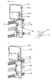
- Fig. 4 shows an embodiment of a pipetting device (700) which is only moved in Z-direction.
- a) Two units (702) are fixed in the support (707). To obtain a sufficiently small raster, e.g. a 9 mm raster, the units (702) are mounted in a staggered manner. Modules (710) on the tools (709) as well as modules (705, 711) on the frame part (703) of the pipette unit (702) are staggered to obtain the required distance between the pipette units (702).
- B) shows the pipette units (709 a, b) and the frames (702 a, b) in a disassembled manner.
- Fig. 5 shows the interface to the frame body (701): a) the frame body is a Y-carriage; the pipetting unit (702) comprises an interacting part (712) which can be engaged with a receiving part (713) of the frame body (701) and releasably fixed. b) shows a detail of the interacting part before engagement. c) shows the frame engaged to the frame body.
- Fig. 6 a shows an adaptor plate (714) for fixing the pipette tool (709) to the frame part (710) of the pipette unit (702).
- Other tools (715, 716) may also be attached to said frame part (710).
- b) shows a detail of the pipette tool (709) fixed to the frame part (702).
- the pipette unit may comprise additional modules.
- such modules comprise sensors.
- sensors Several types of sensors and other modules are shown in Fig. 7 a) to c) , eg. a magnet (720), a hallsensor (721), an init-sensor of the Z-drive (723), an init sensor of the Y-drive (722), an ultrasound sensor (724).
Abstract
Description
- The present invention relates to a pipetting device, method and system with more than one pipetting units, wherein said pipetting units are are movable relative to each other along one axis.
- Pipetting devices are used in automated analyzers for distributing samples or reagents. Pipetting devices comprising more than one pipetting unit are known in the art. Movable pipetting units are useful to transfer samples or reagents from one number of vessels to another number of vessels. Such a device with movable pipetting units is known from
US2001/0036425 . - The present invention provides an improved device with movable pipetting units.
- The present invention relates to a device for aspirating and dispensing more than one liquid sample. The invention also relates to an analyzer comprising such a device. The device comprises a main frame body and more than one pipetting units, said pipetting units extending side by side in parallel with each other. A pipetting unit comprises an interface for interacting with an interface of a pipette tip. It further comprises a first module for aspirating and dispensing a liquid. One preferred embodiment of such a module is a pump. It further comprises a second module for Y-axis movement, and third module for Z-axis movement, wherein said second and third modules function independently. Said second and third modules are preferably actuators. More preferably, said third module is a spindle drive. Said pipette unit further comprises a fourth module for controlling functions of said pipette unit. Preferably, said fourth module is an electronic module controlling all functions of said pipette unit. The pipetting unit comprises two frames for receiving at least one of said modules, wherein said at least one module is mounted in one of said frames. Furthermore, the device comprises an X-transfer mechanism connected to said main frame body to which said pipetting units are connected. Said at least one module of one pipette unit is mounted in one of said two frames, and said at least one module of the adjacent pipette units are mounted in the frame in the location corresponding to the frame of said first pipette unit which is empty.
- The device according to the present invention has the advantage that an appropriate spacing between pipette units can be achieved even if modules required for each pipette unit are too broad to be placed next to each other.
-
-
Fig. 1 shows two pipette units with staggered modules connected to a frame part. -
Fig. 2 shows two pipette units moved into close proximity of each other. -
Fig. 3 a) shows five pipette units connected to one frame part. Four pipette units are in close proximity, the fifth pipette unit is moved independently away from the others. In b) eight pipetting units are shown in close proximity to each other. -
Fig. 4 shows a device with two units fixed to a support for movement in Z-direction, but not in Y-direction (a). In b) shows the two units from a) with individual parts separated. -
Fig. 5 a) to c) show the interface of frame parts with Y-carriage or fixed block. -
Fig. 6 shows an adapter plate (a) and the adapter plate with pipetting unit fixed to the frame part (b). -
Fig. 7 a) to c) show examples of sensors. - In one embodiment of the device hereinbefore described, at least one module is mounted outside of said frame, wherein the said modules of two adjacent pipetting units are staggered. This again allows achieving an appropriate spacing between said pipetting units. In another embodiment, the pipetting unit does not comprise frames. In this embodiment, at least one module is mounted in a staggered fashion on two adjacent pipetting units.
- A preferred shortest distance between said more than one pipette units is 10 mm or shorter. More preferably, the shortest distance between said more than one pipette units is between 10 mm and 1 mm. Further preferred shortest distances are 9 mm, 4.5 mm, 2.25 mm, 1.125 mm.
- In a preferred embodiment, the device hereinbefore described additionally comprises a sixth module, which is a sensor module. Preferred sensor modules are sensors for initializing or determining the position in Y or Z direction of the pipette unit. Preferred sensors for determining the position of the pipette unit in is a ultrasound sensor.
- Preferably, one side of a pipette unit is connected to said Y-axis transfer mechanism.
- Preferably, said pipette units additionally comprise ball bearings, wherein said ball bearings of two adjacent pipette units are staggered.
- The present invention further relates to a method of pipetting samples from a first set of vessels holding said samples to a second set of vessels, wherein the distance between adjacent vessels of the first set of vessels is different from the distance between adjacent vessels of the second set of vessels. Said method comprises aspirating said samples with pipette tips mounted on a device hereinbefore described, wherein the distance between said pipetting units is adjusted to the distance between said first set of vessels by moving the pipetting units along one axis prior to aspiration. The distance between the pipette units to the distance between said second set of vessels prior to dispensing is then adjusted for dispensing said samples into the second set of vessels.
- In a preferred embodiment of the method hereinbefore described, said first set of vessels comprises at least two vessels in a linear arrangement. Preferably, said second set of vessels are integrally formed. In another preferred embodiment, the second set of vessels is only one vessel. In a more preferred embodiment, said second set of vessels comprises a multiwell plate.
- The present invention further relates to a method of isolating and analyzing at least one analyte that may be present in at least one liquid sample in an automated analytical system, comprising the automated steps of providing a first set of vessels comprising said at least one liquid sample to said automated analytical system; aspirating at least a portion of said at least two liquid samples from said first set of vessels with a pipetting device comprising more than one pipetting unit, wherein the distance between said pipetting units is adjusted to the distance between the first set of vessels prior to aspiration; adjusting the distance between said pipetting units to the distance between vessels of a second set of vessels; dispensing said liquid samples into said second set of vessels. The method further comprises the steps of combining together a solid support material and one of said fluid samples in a well of said second set of vessels vessel for a period of time and under conditions sufficient to permit said analyte to be immobilized on the solid support material. isolating the solid support material is then isolated from other material present in the fluid sample in a separation station. The analyte is then purified in the separation station by separating the fluid sample from the solid support material and washing the materials one or more times with a wash buffer. Finally, the analyte is analyzed. In a preferred embodiment, the method comprises at least two liquid samples. In another preferred embodiment, said analyte is a nucleic acid. More preferably, said device comprises the device hereinbefore described.
- The present invention also relates to an analytical system for isolating an analyte, comprising a module for transferring samples from a first set of vessels to a second set of vessels, wherein said module comprises a pipetting device comprising more than one pipetting units, wherein said pipetting units are movable relative to each other along one axis; and a module for isolating said analyte. Preferably, said analytical system additionally comprises a module for analyzing said analyte.
- A device (700) according to the invention comprising a main frame body (701) and two pipetting units (702 a,b) is shown in
Fig. 1 . Each pipetting unit (702) comprises two frames (703, 704). In the non-limiting example shown inFig. 1 , any one of the pipetting unit (702) comprises an electronic module (705). The electronic module (705) of pipetting unit (702 a) is mounted in the lower frame (703), the electronic module (705) of pipetting unit (702 b) is mounted in the upper frame (704). The Y-axis actuators (717) are also mounted on the pipette units in a staggered fashion. The pipetting units also comprise interfaces (706) for interacting with pipette tips (3, 4). -
Fig. 2 shows the two units (702 a, b) as they are moved together, bringing the two pipette tips (3, 4) into close proximity. Corresponding modules (eg 705) are arranged in an nonoverlapping way to allow for an optimal spacing between the two pipetting units.Fig. 3 a) shows a device (700) with five pipette units (702 a to e) with the staggered mount of different modules (705). Four of the pipette units (702 b to e) are shown with a short distance between each other. The fifth unit (702 a) is shown in a position further away.Fig. 3b ) shows a device (700) with eight pipetting units (702), wherein all units (702) are in close proximity to the adjacent units (702) and have needles (80) for pipetting. -
Fig. 4 shows an embodiment of a pipetting device (700) which is only moved in Z-direction. a) Two units (702) are fixed in the support (707). To obtain a sufficiently small raster, e.g. a 9 mm raster, the units (702) are mounted in a staggered manner. Modules (710) on the tools (709) as well as modules (705, 711) on the frame part (703) of the pipette unit (702) are staggered to obtain the required distance between the pipette units (702). B) shows the pipette units (709 a, b) and the frames (702 a, b) in a disassembled manner. -
Fig. 5 shows the interface to the frame body (701): a) the frame body is a Y-carriage; the pipetting unit (702) comprises an interacting part (712) which can be engaged with a receiving part (713) of the frame body (701) and releasably fixed. b) shows a detail of the interacting part before engagement. c) shows the frame engaged to the frame body. -
Fig. 6 a) shows an adaptor plate (714) for fixing the pipette tool (709) to the frame part (710) of the pipette unit (702). Other tools (715, 716) may also be attached to said frame part (710). b) shows a detail of the pipette tool (709) fixed to the frame part (702). - The pipette unit may comprise additional modules. Preferably, such modules comprise sensors. Several types of sensors and other modules are shown in
Fig. 7 a) to c) , eg. a magnet (720), a hallsensor (721), an init-sensor of the Z-drive (723), an init sensor of the Y-drive (722), an ultrasound sensor (724).
Claims (13)
- A device for aspirating and dispensing more than one liquid sample, said device comprising- a main frame body- more than one pipetting units, said pipetting units extending side by side in parallel with each other; wherein a pipetting unit comprises- an interface for interacting with an interface of a pipette tip,- a first module for aspirating and dispensing a liquid,- a second module for Y-axis movement, and third module for Z-Axis movement, wherein said second and third modules are function independently;- a fourth module for controlling functions of said pipette unit;- two frames for receiving at least one of said modules, wherein said at least one module is mounted in one of said frames,- an X-transfer mechanism connected to said main frame body to which said pipetting units are connected;
wherein said at least one module of one pipette unit is mounted in one of said two frames, and said at least one module of the adjacent pipette units are mounted in the frame in the location corresponding to the frame of said first pipette unit which is empty. - The device of claim 1, wherein the shortest distance between said more than one pipette units is 10 mm or shorter.
- The device of claims 1 or 2, wherein the shortest distance between said more than one pipette units is between 10 mm and 1 mm.
- The device of any one of claims 1 to 3, additionally comprising a sensor module.
- The device of any one of claims 1 to 4, wherein one side of a pipette unit is connected to said Y-axis transfer mechanism.
- The device of any one of claims 1 to 5, wherein said pipette units additionally comprise ball bearings, wherein said ball bearings of two adjacent pipette units are staggered.
- A method of pipetting samples from a first set of vessels holding said samples to a second set of vessels, wherein the distance between adjacent vessels of the first set of vessels is different from the distance between adjacent vessels of the second set of vessels, said method comprising- aspirating said samples with pipette tips mounted on a device according to claims 1 to 6, wherein the distance between said pipetting units is adjusted to the distance between said first set of vessels by moving the pipetting units along one axis prior to aspiration;- dispensing said samples into the second set of vessels by adjusting the distance between the pipette units to the distance between said second set of vessels prior to dispensing.
- The method of claim 7, wherein said first set of vessels comprises at least two vessels in a linear arrangement.
- The method of claims 7 or 8, wherein said second set of vessels are integrally formed.
- The method of any one of claims 7 to 9, wherein said second set of vessels comprises a multiwell plate.
- A method of isolating and analyzing at least one analyte that may be present in at least one liquid sample in an automated analytical system, comprising the automated steps of- providing a first set of vessels comprising said at least one liquid sample to said automated analytical system;- aspirating at least a portion of said at least two liquid samples from said first set of vessels with a pipetting device comprising more than one pipetting unit, wherein the distance between said pipetting units is adjusted to the distance between the first set of vessels prior to aspiration;- adjusting the distance between said pipetting units to the distance between vessels of a second set of vessels;- dispensing said liquid samples into said second set of vessels;- combining together a solid support material and one of said fluid samples in a well of said second set of vessels vessel for a period of time and under conditions sufficient to permit said analyte to be immobilized on the solid support material ;- isolating the solid support material from other material present in the fluid sample in a separation station; and- purifying the analyte in the separation station by separating the fluid sample from the solid support material and washing the materials one or more times with a wash buffer; and- analyzing said analyte.
- The method of claim 11, comprising at least two liquid samples.
- The method of claims 11 to 12, wherein said device comprises the device according to any one of claims 1 to 6.
Priority Applications (1)
| Application Number | Priority Date | Filing Date | Title |
|---|---|---|---|
| EP11171558.7A EP2410342B1 (en) | 2010-06-29 | 2011-06-27 | Pipetting device with independently movable pipette tips |
Applications Claiming Priority (2)
| Application Number | Priority Date | Filing Date | Title |
|---|---|---|---|
| EP10167646 | 2010-06-29 | ||
| EP11171558.7A EP2410342B1 (en) | 2010-06-29 | 2011-06-27 | Pipetting device with independently movable pipette tips |
Publications (3)
| Publication Number | Publication Date |
|---|---|
| EP2410342A2 true EP2410342A2 (en) | 2012-01-25 |
| EP2410342A3 EP2410342A3 (en) | 2012-02-29 |
| EP2410342B1 EP2410342B1 (en) | 2020-02-19 |
Family
ID=43334698
Family Applications (1)
| Application Number | Title | Priority Date | Filing Date |
|---|---|---|---|
| EP11171558.7A Active EP2410342B1 (en) | 2010-06-29 | 2011-06-27 | Pipetting device with independently movable pipette tips |
Country Status (2)
| Country | Link |
|---|---|
| US (3) | US8900527B2 (en) |
| EP (1) | EP2410342B1 (en) |
Cited By (13)
| Publication number | Priority date | Publication date | Assignee | Title |
|---|---|---|---|---|
| WO2014041113A1 (en) * | 2012-09-17 | 2014-03-20 | Hamilton Bonaduz Ag | Combined block- and individual-drive device, in particular for pipetting channels |
| DE102013220427A1 (en) * | 2013-10-10 | 2015-04-16 | Hamilton Bonaduz Ag | Movement device with combined individual and block movement drive for several jointly guided movement units |
| WO2018007290A1 (en) | 2016-07-07 | 2018-01-11 | Hamilton Bonaduz Ag | Pipetting device having a displaceable pipetting channel having enlarged suporting location spacing |
| WO2019092089A1 (en) | 2017-11-10 | 2019-05-16 | Hamilton Bonaduz Ag | Pipette device with electromagnetically drivable locking actuator for locking releasably coupled pipette tips |
| US10300480B2 (en) | 2015-10-13 | 2019-05-28 | Roche Molecular Systems, Inc. | Pipetting device for an apparatus for processing a sample or reagent, apparatus for processing a sample or reagent and method for pipetting a sample or reagent |
| WO2019204841A1 (en) | 2018-04-23 | 2019-10-31 | Meon Medical Solutions Gmbh & Co Kg | Automatic analyser and optical measurement method for obtaining measurement signals from liquid media |
| WO2020142798A1 (en) | 2019-01-11 | 2020-07-16 | Meon Medical Solutions Gmbh & Co Kg | Pipetting device and method for the transfer of fluids |
| GB2581800A (en) * | 2019-02-26 | 2020-09-02 | Reliance Prec Limited | Linear actuator |
| EP3769842A1 (en) | 2017-07-14 | 2021-01-27 | Meon Medical Solutions GmbH & Co. KG | Automatic analyzer and method for performing chemical, biochemical and / or immunochemical analyses |
| CN114849809A (en) * | 2022-04-11 | 2022-08-05 | 成都开图医疗系统科技有限公司 | High-precision distance changing device for pipettor and distance dividing plate |
| US11524287B2 (en) | 2017-07-14 | 2022-12-13 | Meon Medical Solutions Gmbh & Co Kg | Automatic pipetting device for transferring samples and/or reagents and method for transferring liquid samples and/or reagents |
| US11635443B2 (en) | 2017-07-14 | 2023-04-25 | Meon Medical Solutions Gmbh & Co Kg | Automatic analyzer and method for carrying out chemical, biochemical, and/or immunochemical analyses |
| LU102878B1 (en) * | 2021-11-15 | 2023-05-15 | Stratec Se | Pipetting unit |
Families Citing this family (11)
| Publication number | Priority date | Publication date | Assignee | Title |
|---|---|---|---|---|
| US20140011290A1 (en) * | 2007-01-16 | 2014-01-09 | Roche Diagnostics Operations, Inc. | Collection of liquid analytical samples for clinical analytical purpose and device thereof |
| US20160266162A1 (en) * | 2013-11-06 | 2016-09-15 | Degree Of Freedom Scientific Machine Co., Ltd. | Fully-automatic pipetting instrument and use thereof |
| US9579646B2 (en) | 2014-07-24 | 2017-02-28 | Accel Biotech, Inc. | Dual tip array dispensing head |
| JP6746574B2 (en) * | 2014-07-28 | 2020-08-26 | ダグラス・サイエンティフィック・エルエルシー | Instruments for analyzing biological samples and reagents |
| CN104614543B (en) * | 2015-01-05 | 2016-01-20 | 嘉兴科瑞迪医疗器械有限公司 | A kind of full-automatic binary channels sample loading gun |
| WO2019017726A2 (en) | 2017-07-21 | 2019-01-24 | Seegene, Inc. | Modules for transferring magnetic beads, automated system comprising the same and method for nucleic acid extraction using the same |
| USD908912S1 (en) * | 2018-04-03 | 2021-01-26 | Tecan Trading Ag | Four channel pipetting arm |
| DE102020200295A1 (en) * | 2020-01-13 | 2021-07-15 | Festo Se & Co. Kg | Positioning system for positioning end effectors |
| LU102489B1 (en) | 2021-02-03 | 2022-08-09 | Stratec Se | Device for moving probes |
| CN114713305A (en) * | 2021-11-11 | 2022-07-08 | 杭州博日科技股份有限公司 | Pipettor adjustment mechanism and pipettor |
| CN115382592A (en) * | 2022-09-09 | 2022-11-25 | 科来思(深圳)科技有限公司 | Double-needle type liquid transfer device with adjustable spacing |
Citations (1)
| Publication number | Priority date | Publication date | Assignee | Title |
|---|---|---|---|---|
| US20010036425A1 (en) | 1995-10-12 | 2001-11-01 | Michel Gazeau | Device for transferring samples of micro-amounts of liquids |
Family Cites Families (24)
| Publication number | Priority date | Publication date | Assignee | Title |
|---|---|---|---|---|
| DE69212156T2 (en) | 1991-05-24 | 1996-12-05 | Harvard College | PARALLEL AND SEQUENTIAL REACTOR |
| US5439649A (en) * | 1993-09-29 | 1995-08-08 | Biogenex Laboratories | Automated staining apparatus |
| ATE215401T1 (en) * | 1997-10-31 | 2002-04-15 | Pe Corp Ny | METHOD AND DEVICE FOR PRODUCING SAMPLE MATRIXES |
| US6103255A (en) * | 1999-04-16 | 2000-08-15 | Rutgers, The State University | Porous polymer scaffolds for tissue engineering |
| AU2002239442A1 (en) | 2000-10-25 | 2002-05-21 | Dna Sciences, Inc. | Variable geometry fluid sample loader |
| DE20018628U1 (en) * | 2000-11-01 | 2002-03-14 | Evotec Biosystems Ag | Sample delivery device |
| WO2002059626A1 (en) | 2001-01-25 | 2002-08-01 | Tecan Trading Ag | Pipetting device |
| JP4016811B2 (en) * | 2002-11-15 | 2007-12-05 | 日立工機株式会社 | Automatic dispensing device |
| JP3765788B2 (en) * | 2002-11-29 | 2006-04-12 | 照明 伊藤 | Sample dispensing system |
| JP4102863B2 (en) * | 2003-02-14 | 2008-06-18 | 株式会社スタックシステム | Dispenser and dispenser |
| DE502004001011D1 (en) | 2003-05-14 | 2006-09-07 | Tecan Trading Ag | Device for precise start-up of microplate wells |
| EP1508809B1 (en) * | 2003-08-20 | 2007-02-28 | Sysmex Corporation | Sample analyzer and nucleic acid detector |
| JP4505230B2 (en) * | 2004-01-20 | 2010-07-21 | シスメックス株式会社 | Analysis equipment |
| CH701163B1 (en) | 2004-06-24 | 2010-12-15 | Tecan Trading Ag | System for manipulating liquid samples as well as apparatus and method for arranging pipette or dispenser tips in such a system. |
| US7662339B2 (en) | 2004-10-22 | 2010-02-16 | Beckman Coulter, Inc. | Apparatus having improved gantry assembly suitable for use in a laboratory environment |
| JP4476906B2 (en) * | 2005-09-02 | 2010-06-09 | 富士フイルム株式会社 | Dispensing device |
| WO2007075891A2 (en) * | 2005-12-23 | 2007-07-05 | Perkinelmer Las, Inc. | Multiplex assays using magnetic and non-magnetic particles |
| US8192698B2 (en) * | 2006-01-27 | 2012-06-05 | Parker-Hannifin Corporation | Sampling probe, gripper and interface for laboratory sample management systems |
| US7988934B2 (en) * | 2006-04-28 | 2011-08-02 | Tecan Trading Ag | Carrier for positioning objects in relation to laboratory articles |
| WO2007132631A1 (en) | 2006-05-17 | 2007-11-22 | Olympus Corporation | Cleaning equipment and automatic analyzer |
| DE102006034245C5 (en) * | 2006-07-21 | 2014-05-28 | Stratec Biomedical Systems Ag | Positioning device for positioning pipettes |
| US8900878B2 (en) | 2008-11-28 | 2014-12-02 | Roche Molecular Systems Inc. | Pipetting device, modular pipetting unit, pipetting system and method for pipetting of fluid samples |
| JP5846773B2 (en) * | 2010-06-29 | 2016-01-20 | エフ.ホフマン−ラ ロシュ アーゲーF. Hoffmann−La Roche Aktiengesellschaft | Sample distribution |
| ES2534361T3 (en) * | 2011-06-20 | 2015-04-21 | F. Hoffmann-La Roche Ag | Device for uncovering and recapping sample tubes |
-
2011
- 2011-06-27 US US13/169,593 patent/US8900527B2/en active Active
- 2011-06-27 EP EP11171558.7A patent/EP2410342B1/en active Active
-
2014
- 2014-10-16 US US14/515,668 patent/US9101922B2/en active Active
-
2015
- 2015-07-06 US US14/792,155 patent/US9244087B2/en active Active
Patent Citations (1)
| Publication number | Priority date | Publication date | Assignee | Title |
|---|---|---|---|---|
| US20010036425A1 (en) | 1995-10-12 | 2001-11-01 | Michel Gazeau | Device for transferring samples of micro-amounts of liquids |
Cited By (24)
| Publication number | Priority date | Publication date | Assignee | Title |
|---|---|---|---|---|
| WO2014041113A1 (en) * | 2012-09-17 | 2014-03-20 | Hamilton Bonaduz Ag | Combined block- and individual-drive device, in particular for pipetting channels |
| US9664263B2 (en) | 2013-10-10 | 2017-05-30 | Hamilton Bonaduz Ag | Movement device comprising a combined individual movement and block movement drive for a plurality of jointly guided movement units |
| EP2871481A1 (en) * | 2013-10-10 | 2015-05-13 | Hamilton Bonaduz AG | Movement device with combined individual and block movement drive for multiple jointly guided moving units |
| DE102013220427A1 (en) * | 2013-10-10 | 2015-04-16 | Hamilton Bonaduz Ag | Movement device with combined individual and block movement drive for several jointly guided movement units |
| US10300480B2 (en) | 2015-10-13 | 2019-05-28 | Roche Molecular Systems, Inc. | Pipetting device for an apparatus for processing a sample or reagent, apparatus for processing a sample or reagent and method for pipetting a sample or reagent |
| US10493444B2 (en) | 2015-10-13 | 2019-12-03 | Roche Molecular Systems, Inc. | Pipetting device for an apparatus for processing a sample or reagent, apparatus for processing a sample or reagent and method for pipetting a sample or reagent |
| US10837979B2 (en) | 2016-07-07 | 2020-11-17 | Hamilton Bonaduz Ag | Pipetting device having a displaceable pipetting channel having enlarged supporting location spacing |
| WO2018007290A1 (en) | 2016-07-07 | 2018-01-11 | Hamilton Bonaduz Ag | Pipetting device having a displaceable pipetting channel having enlarged suporting location spacing |
| DE102016212444A1 (en) | 2016-07-07 | 2018-01-11 | Hamilton Bonaduz Ag | Pipetting device with displaceable pipetting channel with increased storage location distance |
| US11867710B2 (en) | 2017-07-14 | 2024-01-09 | Meon Medical Solutions Gmbh & Co Kg | Automatic analyzer and method for carrying out chemical, biochemical and/or immunochemical analyses |
| US11635443B2 (en) | 2017-07-14 | 2023-04-25 | Meon Medical Solutions Gmbh & Co Kg | Automatic analyzer and method for carrying out chemical, biochemical, and/or immunochemical analyses |
| US11524287B2 (en) | 2017-07-14 | 2022-12-13 | Meon Medical Solutions Gmbh & Co Kg | Automatic pipetting device for transferring samples and/or reagents and method for transferring liquid samples and/or reagents |
| EP3769842A1 (en) | 2017-07-14 | 2021-01-27 | Meon Medical Solutions GmbH & Co. KG | Automatic analyzer and method for performing chemical, biochemical and / or immunochemical analyses |
| WO2019092089A1 (en) | 2017-11-10 | 2019-05-16 | Hamilton Bonaduz Ag | Pipette device with electromagnetically drivable locking actuator for locking releasably coupled pipette tips |
| DE102017220042A1 (en) | 2017-11-10 | 2019-05-16 | Hamilton Bonaduz Ag | Pipetting device with electromagnetically driven locking actuator for locking detachably coupled pipetting tips |
| WO2019204841A1 (en) | 2018-04-23 | 2019-10-31 | Meon Medical Solutions Gmbh & Co Kg | Automatic analyser and optical measurement method for obtaining measurement signals from liquid media |
| WO2020142798A1 (en) | 2019-01-11 | 2020-07-16 | Meon Medical Solutions Gmbh & Co Kg | Pipetting device and method for the transfer of fluids |
| WO2020174207A1 (en) * | 2019-02-26 | 2020-09-03 | Reliance Precision Limited | Linear actuator |
| GB2581800A (en) * | 2019-02-26 | 2020-09-02 | Reliance Prec Limited | Linear actuator |
| GB2581800B (en) * | 2019-02-26 | 2023-08-09 | Reliance Rg Ltd | Linear actuator |
| LU102878B1 (en) * | 2021-11-15 | 2023-05-15 | Stratec Se | Pipetting unit |
| EP4180822A1 (en) | 2021-11-15 | 2023-05-17 | Stratec SE | Pipetting unit |
| CN114849809A (en) * | 2022-04-11 | 2022-08-05 | 成都开图医疗系统科技有限公司 | High-precision distance changing device for pipettor and distance dividing plate |
| CN114849809B (en) * | 2022-04-11 | 2024-03-22 | 成都开图医疗系统科技有限公司 | High-precision distance changing device for pipettor and distance separating plate |
Also Published As
| Publication number | Publication date |
|---|---|
| EP2410342B1 (en) | 2020-02-19 |
| US20150096356A1 (en) | 2015-04-09 |
| US20150309065A1 (en) | 2015-10-29 |
| US8900527B2 (en) | 2014-12-02 |
| US20120186367A1 (en) | 2012-07-26 |
| US9101922B2 (en) | 2015-08-11 |
| US9244087B2 (en) | 2016-01-26 |
| EP2410342A3 (en) | 2012-02-29 |
Similar Documents
| Publication | Publication Date | Title |
|---|---|---|
| US9244087B2 (en) | Methods for using a pipetting device with independently movable pipette units | |
| EP2263802A1 (en) | System and method for dispensing fluids | |
| US9733265B2 (en) | Method for adjusting position of aspirator and sample processing apparatus | |
| US9383379B2 (en) | Sample distribution in a method for isolating analytes in fluid samples in an automated system | |
| EP2333560A2 (en) | Method for separating and detecting an analyte | |
| EP2338600B1 (en) | Process head positioning | |
| US20110300620A1 (en) | Combo-tip Rack | |
| US9696327B2 (en) | Consumable hardware coding system | |
| WO2010106885A1 (en) | Automatic analytical device | |
| EP2602626A1 (en) | Workflow timing between modules | |
| US9377479B2 (en) | System and method for the automated processing of fluids, method for determining the matching of objects | |
| EP3120930A1 (en) | Pipette device and liquid treatment system | |
| US10337967B2 (en) | Magnetic base for collection and release of paramagnetic particles | |
| CN109696556B (en) | Pipetting device and pipetting device positioning system | |
| CN1540354A (en) | Test element holder with probe guide for analyzer | |
| EP1403644A1 (en) | Fluid analyzer | |
| CN104459173B (en) | A kind of sample transfer equipment and sample conveyance system | |
| US20090090198A1 (en) | Separation apparatus | |
| US20090206970A1 (en) | Device for coupling an attachment | |
| JP2009168728A (en) | Analyte handling apparatus | |
| US20230373107A1 (en) | Gripping apparatus for gripping sample container | |
| EP4006549A1 (en) | Device for simultaneous analysis of multiple biomarkers and method for simultaneous analysis of multiple biomarkers | |
| EP4184176A1 (en) | Method for detection of a bottom of at least one well | |
| CN117405907A (en) | Automatic biological sample detection device and detection method based on coded liquid phase chip | |
| JP2015125050A (en) | Analysis system, conveyance unit, and analysis device |
Legal Events
| Date | Code | Title | Description |
|---|---|---|---|
| AK | Designated contracting states |
Kind code of ref document: A2 Designated state(s): AL AT BE BG CH CY CZ DE DK EE ES FI FR GB GR HR HU IE IS IT LI LT LU LV MC MK MT NL NO PL PT RO RS SE SI SK SM TR |
|
| AX | Request for extension of the european patent |
Extension state: BA ME |
|
| PUAI | Public reference made under article 153(3) epc to a published international application that has entered the european phase |
Free format text: ORIGINAL CODE: 0009012 |
|
| PUAL | Search report despatched |
Free format text: ORIGINAL CODE: 0009013 |
|
| AK | Designated contracting states |
Kind code of ref document: A3 Designated state(s): AL AT BE BG CH CY CZ DE DK EE ES FI FR GB GR HR HU IE IS IT LI LT LU LV MC MK MT NL NO PL PT RO RS SE SI SK SM TR |
|
| AX | Request for extension of the european patent |
Extension state: BA ME |
|
| RIC1 | Information provided on ipc code assigned before grant |
Ipc: G01N 35/10 20060101AFI20120125BHEP |
|
| 17P | Request for examination filed |
Effective date: 20120829 |
|
| STAA | Information on the status of an ep patent application or granted ep patent |
Free format text: STATUS: EXAMINATION IS IN PROGRESS |
|
| 17Q | First examination report despatched |
Effective date: 20181206 |
|
| RIC1 | Information provided on ipc code assigned before grant |
Ipc: B01L 3/02 20060101ALI20190709BHEP Ipc: G01N 35/10 20060101AFI20190709BHEP |
|
| GRAP | Despatch of communication of intention to grant a patent |
Free format text: ORIGINAL CODE: EPIDOSNIGR1 |
|
| STAA | Information on the status of an ep patent application or granted ep patent |
Free format text: STATUS: GRANT OF PATENT IS INTENDED |
|
| INTG | Intention to grant announced |
Effective date: 20190827 |
|
| GRAS | Grant fee paid |
Free format text: ORIGINAL CODE: EPIDOSNIGR3 |
|
| GRAA | (expected) grant |
Free format text: ORIGINAL CODE: 0009210 |
|
| STAA | Information on the status of an ep patent application or granted ep patent |
Free format text: STATUS: THE PATENT HAS BEEN GRANTED |
|
| AK | Designated contracting states |
Kind code of ref document: B1 Designated state(s): AL AT BE BG CH CY CZ DE DK EE ES FI FR GB GR HR HU IE IS IT LI LT LU LV MC MK MT NL NO PL PT RO RS SE SI SK SM TR |
|
| REG | Reference to a national code |
Ref country code: GB Ref legal event code: FG4D |
|
| REG | Reference to a national code |
Ref country code: CH Ref legal event code: EP |
|
| REG | Reference to a national code |
Ref country code: DE Ref legal event code: R096 Ref document number: 602011065056 Country of ref document: DE |
|
| REG | Reference to a national code |
Ref country code: AT Ref legal event code: REF Ref document number: 1235564 Country of ref document: AT Kind code of ref document: T Effective date: 20200315 |
|
| REG | Reference to a national code |
Ref country code: IE Ref legal event code: FG4D |
|
| REG | Reference to a national code |
Ref country code: NL Ref legal event code: MP Effective date: 20200219 |
|
| PG25 | Lapsed in a contracting state [announced via postgrant information from national office to epo] |
Ref country code: FI Free format text: LAPSE BECAUSE OF FAILURE TO SUBMIT A TRANSLATION OF THE DESCRIPTION OR TO PAY THE FEE WITHIN THE PRESCRIBED TIME-LIMIT Effective date: 20200219 Ref country code: RS Free format text: LAPSE BECAUSE OF FAILURE TO SUBMIT A TRANSLATION OF THE DESCRIPTION OR TO PAY THE FEE WITHIN THE PRESCRIBED TIME-LIMIT Effective date: 20200219 Ref country code: NO Free format text: LAPSE BECAUSE OF FAILURE TO SUBMIT A TRANSLATION OF THE DESCRIPTION OR TO PAY THE FEE WITHIN THE PRESCRIBED TIME-LIMIT Effective date: 20200519 |
|
| REG | Reference to a national code |
Ref country code: LT Ref legal event code: MG4D |
|
| PG25 | Lapsed in a contracting state [announced via postgrant information from national office to epo] |
Ref country code: IS Free format text: LAPSE BECAUSE OF FAILURE TO SUBMIT A TRANSLATION OF THE DESCRIPTION OR TO PAY THE FEE WITHIN THE PRESCRIBED TIME-LIMIT Effective date: 20200619 Ref country code: BG Free format text: LAPSE BECAUSE OF FAILURE TO SUBMIT A TRANSLATION OF THE DESCRIPTION OR TO PAY THE FEE WITHIN THE PRESCRIBED TIME-LIMIT Effective date: 20200519 Ref country code: GR Free format text: LAPSE BECAUSE OF FAILURE TO SUBMIT A TRANSLATION OF THE DESCRIPTION OR TO PAY THE FEE WITHIN THE PRESCRIBED TIME-LIMIT Effective date: 20200520 Ref country code: HR Free format text: LAPSE BECAUSE OF FAILURE TO SUBMIT A TRANSLATION OF THE DESCRIPTION OR TO PAY THE FEE WITHIN THE PRESCRIBED TIME-LIMIT Effective date: 20200219 Ref country code: SE Free format text: LAPSE BECAUSE OF FAILURE TO SUBMIT A TRANSLATION OF THE DESCRIPTION OR TO PAY THE FEE WITHIN THE PRESCRIBED TIME-LIMIT Effective date: 20200219 Ref country code: LV Free format text: LAPSE BECAUSE OF FAILURE TO SUBMIT A TRANSLATION OF THE DESCRIPTION OR TO PAY THE FEE WITHIN THE PRESCRIBED TIME-LIMIT Effective date: 20200219 |
|
| PG25 | Lapsed in a contracting state [announced via postgrant information from national office to epo] |
Ref country code: NL Free format text: LAPSE BECAUSE OF FAILURE TO SUBMIT A TRANSLATION OF THE DESCRIPTION OR TO PAY THE FEE WITHIN THE PRESCRIBED TIME-LIMIT Effective date: 20200219 |
|
| PG25 | Lapsed in a contracting state [announced via postgrant information from national office to epo] |
Ref country code: DK Free format text: LAPSE BECAUSE OF FAILURE TO SUBMIT A TRANSLATION OF THE DESCRIPTION OR TO PAY THE FEE WITHIN THE PRESCRIBED TIME-LIMIT Effective date: 20200219 Ref country code: EE Free format text: LAPSE BECAUSE OF FAILURE TO SUBMIT A TRANSLATION OF THE DESCRIPTION OR TO PAY THE FEE WITHIN THE PRESCRIBED TIME-LIMIT Effective date: 20200219 Ref country code: SM Free format text: LAPSE BECAUSE OF FAILURE TO SUBMIT A TRANSLATION OF THE DESCRIPTION OR TO PAY THE FEE WITHIN THE PRESCRIBED TIME-LIMIT Effective date: 20200219 Ref country code: SK Free format text: LAPSE BECAUSE OF FAILURE TO SUBMIT A TRANSLATION OF THE DESCRIPTION OR TO PAY THE FEE WITHIN THE PRESCRIBED TIME-LIMIT Effective date: 20200219 Ref country code: PT Free format text: LAPSE BECAUSE OF FAILURE TO SUBMIT A TRANSLATION OF THE DESCRIPTION OR TO PAY THE FEE WITHIN THE PRESCRIBED TIME-LIMIT Effective date: 20200712 Ref country code: ES Free format text: LAPSE BECAUSE OF FAILURE TO SUBMIT A TRANSLATION OF THE DESCRIPTION OR TO PAY THE FEE WITHIN THE PRESCRIBED TIME-LIMIT Effective date: 20200219 Ref country code: LT Free format text: LAPSE BECAUSE OF FAILURE TO SUBMIT A TRANSLATION OF THE DESCRIPTION OR TO PAY THE FEE WITHIN THE PRESCRIBED TIME-LIMIT Effective date: 20200219 Ref country code: RO Free format text: LAPSE BECAUSE OF FAILURE TO SUBMIT A TRANSLATION OF THE DESCRIPTION OR TO PAY THE FEE WITHIN THE PRESCRIBED TIME-LIMIT Effective date: 20200219 Ref country code: CZ Free format text: LAPSE BECAUSE OF FAILURE TO SUBMIT A TRANSLATION OF THE DESCRIPTION OR TO PAY THE FEE WITHIN THE PRESCRIBED TIME-LIMIT Effective date: 20200219 |
|
| REG | Reference to a national code |
Ref country code: AT Ref legal event code: MK05 Ref document number: 1235564 Country of ref document: AT Kind code of ref document: T Effective date: 20200219 |
|
| REG | Reference to a national code |
Ref country code: DE Ref legal event code: R097 Ref document number: 602011065056 Country of ref document: DE |
|
| PLBE | No opposition filed within time limit |
Free format text: ORIGINAL CODE: 0009261 |
|
| STAA | Information on the status of an ep patent application or granted ep patent |
Free format text: STATUS: NO OPPOSITION FILED WITHIN TIME LIMIT |
|
| 26N | No opposition filed |
Effective date: 20201120 |
|
| PG25 | Lapsed in a contracting state [announced via postgrant information from national office to epo] |
Ref country code: IT Free format text: LAPSE BECAUSE OF FAILURE TO SUBMIT A TRANSLATION OF THE DESCRIPTION OR TO PAY THE FEE WITHIN THE PRESCRIBED TIME-LIMIT Effective date: 20200219 Ref country code: MC Free format text: LAPSE BECAUSE OF FAILURE TO SUBMIT A TRANSLATION OF THE DESCRIPTION OR TO PAY THE FEE WITHIN THE PRESCRIBED TIME-LIMIT Effective date: 20200219 Ref country code: AT Free format text: LAPSE BECAUSE OF FAILURE TO SUBMIT A TRANSLATION OF THE DESCRIPTION OR TO PAY THE FEE WITHIN THE PRESCRIBED TIME-LIMIT Effective date: 20200219 |
|
| PG25 | Lapsed in a contracting state [announced via postgrant information from national office to epo] |
Ref country code: SI Free format text: LAPSE BECAUSE OF FAILURE TO SUBMIT A TRANSLATION OF THE DESCRIPTION OR TO PAY THE FEE WITHIN THE PRESCRIBED TIME-LIMIT Effective date: 20200219 Ref country code: PL Free format text: LAPSE BECAUSE OF FAILURE TO SUBMIT A TRANSLATION OF THE DESCRIPTION OR TO PAY THE FEE WITHIN THE PRESCRIBED TIME-LIMIT Effective date: 20200219 |
|
| PG25 | Lapsed in a contracting state [announced via postgrant information from national office to epo] |
Ref country code: LU Free format text: LAPSE BECAUSE OF NON-PAYMENT OF DUE FEES Effective date: 20200627 |
|
| REG | Reference to a national code |
Ref country code: BE Ref legal event code: MM Effective date: 20200630 |
|
| PG25 | Lapsed in a contracting state [announced via postgrant information from national office to epo] |
Ref country code: IE Free format text: LAPSE BECAUSE OF NON-PAYMENT OF DUE FEES Effective date: 20200627 |
|
| PG25 | Lapsed in a contracting state [announced via postgrant information from national office to epo] |
Ref country code: BE Free format text: LAPSE BECAUSE OF NON-PAYMENT OF DUE FEES Effective date: 20200630 |
|
| PG25 | Lapsed in a contracting state [announced via postgrant information from national office to epo] |
Ref country code: TR Free format text: LAPSE BECAUSE OF FAILURE TO SUBMIT A TRANSLATION OF THE DESCRIPTION OR TO PAY THE FEE WITHIN THE PRESCRIBED TIME-LIMIT Effective date: 20200219 Ref country code: MT Free format text: LAPSE BECAUSE OF FAILURE TO SUBMIT A TRANSLATION OF THE DESCRIPTION OR TO PAY THE FEE WITHIN THE PRESCRIBED TIME-LIMIT Effective date: 20200219 Ref country code: CY Free format text: LAPSE BECAUSE OF FAILURE TO SUBMIT A TRANSLATION OF THE DESCRIPTION OR TO PAY THE FEE WITHIN THE PRESCRIBED TIME-LIMIT Effective date: 20200219 |
|
| PG25 | Lapsed in a contracting state [announced via postgrant information from national office to epo] |
Ref country code: MK Free format text: LAPSE BECAUSE OF FAILURE TO SUBMIT A TRANSLATION OF THE DESCRIPTION OR TO PAY THE FEE WITHIN THE PRESCRIBED TIME-LIMIT Effective date: 20200219 Ref country code: AL Free format text: LAPSE BECAUSE OF FAILURE TO SUBMIT A TRANSLATION OF THE DESCRIPTION OR TO PAY THE FEE WITHIN THE PRESCRIBED TIME-LIMIT Effective date: 20200219 |
|
| PGFP | Annual fee paid to national office [announced via postgrant information from national office to epo] |
Ref country code: FR Payment date: 20230509 Year of fee payment: 13 Ref country code: DE Payment date: 20230509 Year of fee payment: 13 |
|
| PGFP | Annual fee paid to national office [announced via postgrant information from national office to epo] |
Ref country code: GB Payment date: 20230510 Year of fee payment: 13 Ref country code: CH Payment date: 20230701 Year of fee payment: 13 |