EP2410302A1 - Liquid level detector - Google Patents
Liquid level detector Download PDFInfo
- Publication number
- EP2410302A1 EP2410302A1 EP10753527A EP10753527A EP2410302A1 EP 2410302 A1 EP2410302 A1 EP 2410302A1 EP 10753527 A EP10753527 A EP 10753527A EP 10753527 A EP10753527 A EP 10753527A EP 2410302 A1 EP2410302 A1 EP 2410302A1
- Authority
- EP
- European Patent Office
- Prior art keywords
- contact
- conductive segments
- liquid level
- sliding
- level detecting
- Prior art date
- Legal status (The legal status is an assumption and is not a legal conclusion. Google has not performed a legal analysis and makes no representation as to the accuracy of the status listed.)
- Withdrawn
Links
- 239000007788 liquid Substances 0.000 title claims description 80
- 239000000758 substrate Substances 0.000 claims description 8
- 239000004020 conductor Substances 0.000 description 26
- 238000001514 detection method Methods 0.000 description 10
- 230000007423 decrease Effects 0.000 description 9
- 238000010586 diagram Methods 0.000 description 4
- 239000000446 fuel Substances 0.000 description 4
- 230000002093 peripheral effect Effects 0.000 description 4
- OKKJLVBELUTLKV-UHFFFAOYSA-N Methanol Chemical compound OC OKKJLVBELUTLKV-UHFFFAOYSA-N 0.000 description 3
- 230000000694 effects Effects 0.000 description 3
- 238000002474 experimental method Methods 0.000 description 3
- 239000002828 fuel tank Substances 0.000 description 3
- 229910001020 Au alloy Inorganic materials 0.000 description 2
- RYGMFSIKBFXOCR-UHFFFAOYSA-N Copper Chemical compound [Cu] RYGMFSIKBFXOCR-UHFFFAOYSA-N 0.000 description 2
- 229910000881 Cu alloy Inorganic materials 0.000 description 2
- LFQSCWFLJHTTHZ-UHFFFAOYSA-N Ethanol Chemical compound CCO LFQSCWFLJHTTHZ-UHFFFAOYSA-N 0.000 description 2
- 238000005452 bending Methods 0.000 description 2
- 229910052802 copper Inorganic materials 0.000 description 2
- 239000010949 copper Substances 0.000 description 2
- 230000007797 corrosion Effects 0.000 description 2
- 238000005260 corrosion Methods 0.000 description 2
- PCHJSUWPFVWCPO-UHFFFAOYSA-N gold Chemical compound [Au] PCHJSUWPFVWCPO-UHFFFAOYSA-N 0.000 description 2
- 229910052737 gold Inorganic materials 0.000 description 2
- 239000010931 gold Substances 0.000 description 2
- 239000003353 gold alloy Substances 0.000 description 2
- 239000000463 material Substances 0.000 description 2
- 238000005259 measurement Methods 0.000 description 2
- 238000012986 modification Methods 0.000 description 2
- 230000004048 modification Effects 0.000 description 2
- SWELZOZIOHGSPA-UHFFFAOYSA-N palladium silver Chemical compound [Pd].[Ag] SWELZOZIOHGSPA-UHFFFAOYSA-N 0.000 description 2
- 229910001220 stainless steel Inorganic materials 0.000 description 2
- NINIDFKCEFEMDL-UHFFFAOYSA-N Sulfur Chemical compound [S] NINIDFKCEFEMDL-UHFFFAOYSA-N 0.000 description 1
- 229910052782 aluminium Inorganic materials 0.000 description 1
- XAGFODPZIPBFFR-UHFFFAOYSA-N aluminium Chemical compound [Al] XAGFODPZIPBFFR-UHFFFAOYSA-N 0.000 description 1
- 239000000470 constituent Substances 0.000 description 1
- 230000006866 deterioration Effects 0.000 description 1
- 238000005868 electrolysis reaction Methods 0.000 description 1
- 239000003792 electrolyte Substances 0.000 description 1
- 239000011521 glass Substances 0.000 description 1
- 238000001746 injection moulding Methods 0.000 description 1
- 238000003780 insertion Methods 0.000 description 1
- 230000037431 insertion Effects 0.000 description 1
- 229910052751 metal Inorganic materials 0.000 description 1
- 239000002184 metal Substances 0.000 description 1
- 238000000034 method Methods 0.000 description 1
- 238000000465 moulding Methods 0.000 description 1
- KDLHZDBZIXYQEI-UHFFFAOYSA-N palladium Substances [Pd] KDLHZDBZIXYQEI-UHFFFAOYSA-N 0.000 description 1
- 238000012545 processing Methods 0.000 description 1
- 229910001925 ruthenium oxide Inorganic materials 0.000 description 1
- WOCIAKWEIIZHES-UHFFFAOYSA-N ruthenium(iv) oxide Chemical compound O=[Ru]=O WOCIAKWEIIZHES-UHFFFAOYSA-N 0.000 description 1
- 239000010935 stainless steel Substances 0.000 description 1
- 229910052717 sulfur Inorganic materials 0.000 description 1
- 239000011593 sulfur Substances 0.000 description 1
- 229920003002 synthetic resin Polymers 0.000 description 1
- 239000000057 synthetic resin Substances 0.000 description 1
- 238000012360 testing method Methods 0.000 description 1
Images



Classifications
-
- G—PHYSICS
- G01—MEASURING; TESTING
- G01F—MEASURING VOLUME, VOLUME FLOW, MASS FLOW OR LIQUID LEVEL; METERING BY VOLUME
- G01F23/00—Indicating or measuring liquid level or level of fluent solid material, e.g. indicating in terms of volume or indicating by means of an alarm
- G01F23/30—Indicating or measuring liquid level or level of fluent solid material, e.g. indicating in terms of volume or indicating by means of an alarm by floats
- G01F23/32—Indicating or measuring liquid level or level of fluent solid material, e.g. indicating in terms of volume or indicating by means of an alarm by floats using rotatable arms or other pivotable transmission elements
- G01F23/36—Indicating or measuring liquid level or level of fluent solid material, e.g. indicating in terms of volume or indicating by means of an alarm by floats using rotatable arms or other pivotable transmission elements using electrically actuated indicating means
- G01F23/363—Indicating or measuring liquid level or level of fluent solid material, e.g. indicating in terms of volume or indicating by means of an alarm by floats using rotatable arms or other pivotable transmission elements using electrically actuated indicating means using electromechanically actuated indicating means
-
- H—ELECTRICITY
- H01—ELECTRIC ELEMENTS
- H01C—RESISTORS
- H01C10/00—Adjustable resistors
- H01C10/30—Adjustable resistors the contact sliding along resistive element
- H01C10/32—Adjustable resistors the contact sliding along resistive element the contact moving in an arcuate path
- H01C10/34—Adjustable resistors the contact sliding along resistive element the contact moving in an arcuate path the contact or the associated conducting structure riding on collector formed as a ring or portion thereof
-
- H—ELECTRICITY
- H01—ELECTRIC ELEMENTS
- H01C—RESISTORS
- H01C10/00—Adjustable resistors
- H01C10/30—Adjustable resistors the contact sliding along resistive element
- H01C10/32—Adjustable resistors the contact sliding along resistive element the contact moving in an arcuate path
Definitions
- the present invention relates to a contact type liquid level detecting apparatus which measures a remaining amount of fuel by detecting the liquid level, and particularly to a liquid level detecting apparatus that realizes highly reliable liquid level detection.
- an arm 120 which is attached to a float 121, is pivotally moved in accordance with a change of the level of the liquid surface S.
- Contacts 111 and 112 which are provided at a sliding body 110 that moves integrally with the arm 120, slidingly contact on conductor electrodes 150A and 150B of a resistance plate 130.
- the liquid level is detected by detecting a voltage value that changes accordingly.
- the resistance plate 130 is configured by an Ag/Pd-type conductor circuit portion, which is not illustrated in the figure, sintered on an aluminum substrate.
- the metal contacts 111 and 112 of the sliding body 110 contact with and slide on the resistance plate 130.
- the contacts 111 and 112 contact with the conductor electrodes 150A and 150B at the side of the resistance plate 130 as the contacts 111 and 112 are pushed by contact springs 140A and 140B.
- the parts of the contacts 111 and 112 that contact with the conductor electrodes 150A and 150B are typically formed to have an R-shaped cross-section. Therefore, the contacts 111 and 112 contact with the conductor electrodes 150A and 150B in a point-contact mode.
- An object of the invention is to provide a liquid level detecting apparatus that realizes highly reliable liquid level detection all the time, wherein the change of a contact over time is stabilized by lowering intense wear of the contact in the initial sliding stage and imparting stabilized wear characteristics from the initial stage of sliding.
- a liquid level detecting apparatus includes following features (1) to (6).
- liquid level detecting apparatus of the above mentioned (1) intense wear of the contact in the initial sliding stage is lowered by making the top portion of the contact that contacts the conductive segments flat.
- stabilized wear characteristics is imparted from the initial stage of sliding and the change of a contact over time is stabilized. It is possible to realize highly reliable liquid level detection all the time.
- the liquid level detecting apparatus of the above mentioned (2) since the top portion of the contact has such a size that the contact does not simultaneously contact three or more neighboring conductive segments, it is possible for the apparatus to maintain a high level of liquid level detecting precision.
- the liquid level detecting apparatus of the above mentioned (3) since the force per unit area applied to the top portion of the contact decreases greatly, and the contact has such a size that the contact does not simultaneously contact three or more neighboring conductive segments, it is possible to maintain a high level of liquid level detecting precision.
- the liquid level detecting apparatus of the above mentioned (4) in the initial sliding stage when the top portion of the conductive segments does not become flat, even if the diameter ⁇ of the top portion of the contact is less than 0.7 [mm], it is possible that the top portion of the contact have such a size that the contact does not simultaneously contact three or more neighboring conductive segments.
- the wear of both the contact and the conductive segments in the initial sliding stage can be greatly lowered by making both the top portion of the contact that contacts with the conductive segments and the top portion of the conductive segments that contact with the contact flat.
- the top portions of the conductive segments becomes natural and flat by slidingly contacting onto the flat top portion of the contact in the initial sliding stage. As a result, without processing the part which should become the top portions of the conductive segments, the wear of both the contact and the conductive segments after the top portion of the conductive segments has become flat can be greatly lowered.
- liquid level detecting apparatus of the invention intense wear of the contact in the initial sliding stage is lowered by making the top portion of the contact which contacts with the conductive segments flat.
- stabilized wear characteristics is imparted from the initial stage of sliding and the change of a contact over time is stabilized. It is possible to realize highly reliable liquid level detection all the time.
- Fig. 1 is a plan view showing a liquid level detecting apparatus of an embodiment of the present invention.
- Fig. 2 is a perspective view showing a sliding body in Fig. 1 .
- Fig. 3 is a side view of the sliding body.
- Fig. 4A is a side view showing a contact of the invention and
- Fig. 4B is a plan view of the contact.
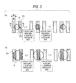
- Fig. 5A is an explanatory diagram showing the relationship of the contact (diameter ⁇ of the contact is 0.3 [mm]) of the invention and conductor pattern of the conductor segments, and Fig.
- FIG. 5B is an explanatory diagram showing the relationship of the contact (diameter ⁇ of the contact is 0.6 [mm]) of the invention and conductor pattern of the conductor segments.
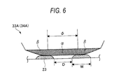
- Fig. 6 is a VI-VI line section view of Fig. 5 .
- Figs. 7A and 7B are side views for illustrating the shapes of the conductor segments which slidingly contact the contact before the sliding starts and in the initial sliding stage, respectively.
- Figs. 8A and 8B are side views for illustrating the contacting state of the conductor segment and the contact of the invention before the sliding starts and in the initial sliding stage, respectively.
- FIG. 9 is a chart of the relationship of the number of sliding times and the wear amount of the contact, which is obtained when comparison experiment are made by making use of the liquid level detecting apparatuses of the invention and a conventional one.
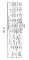
- Fig. 10 is a table showing the result of inspecting contacting areas and surface pressures for various contact diameters by making use of the liquid level detecting apparatus of the invention.
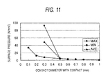
- Fig. 11 is a chart showing the relationship of the various contact diameters and the surface pressures [N/mm 2 ] shown in Fig. 10 .
- Fig. 1 shows a liquid level detecting apparatus 1 according to the invention.
- the liquid level detecting apparatus 1 is mounted on an automobile in order to detect a height of a liquid surface S of liquid (fuel) L within a fuel tank outside the figure.
- the liquid level detecting apparatus 1 includes a frame 10, a resistance plate 20, a sliding body 30 and a float arm 40.
- a float 41 which moves upward and downward in accordance with a change of the level of the liquid surface S of liquid (fuel) L inside the fuel tank, is supported integrally at a distal end of the float arm 40.
- the resistance plate 20 and the sliding body 30 are provided in the frame 10.
- the sliding body 30 slides on a conductive pattern 20B (described later) of the resistance plate 20 in conjunction with the rotation of the float arm 40.
- the conductive pattern 20B made of silver palladium (AgPd) which has excellent electrical conductivity and also is excellent in deterioration resistance and corrosion resistance, is provided on the resistance plate 20.
- the conductive pattern 20B includes an arc-shaped first sliding portion 21 and an arc-shaped second sliding portion 22 that are formed on an insulating substrate 20A.
- conductive segments 23, having roughly pectinate, are arranged at certain intervals in a sliding direction of the sliding body 30, and an arc-shaped resistor 24 is formed on the conductive segments 23.
- the resistor 24 is a resistance layer made of ruthenium oxide which is excellent in sulfur resistance and is less liable to be deteriorated and corroded by electrolysis even when it is exposed to an electrolyte such as ethanol and methanol.
- Adjacent conductive segments 23 are connected together via the resistor 24, a contact spring 32, a first contact 33 and a second contact 34 (the contact spring 32, the first contact 33 and the second contact 34 will be described later).
- the first sliding portion 21 is electrically connected to output terminal 25A.
- conductive segments 23, havingroughly pectinate, are arranged at certain intervals in a sliding direction of the sliding body 30, and the arc-shaped second sliding portion 22 is formed by conductive materials (silver palladium).
- the second sliding portion 22 is electrically connected to 25B.
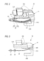
- the sliding body 30 has, as shown in Figs. 2 and 3 , an arm holder 31, a contact spring 32, a first contact 33 and a second contact 34 that are fixed to one end of the contact spring 32.
- the arm holder 31 is formed to be roughly U-shaped when viewed from the side (see Figs. 2 and 3 ).
- An upper holding portion 31A and a lower holding portion 31B are formed to be parallel to each other, and are interconnected by an interconnecting portion 31C.
- the arm holder 31 of the embodiment is formed by injection molding synthetic resin.
- a shaft hole 311 for the passage of the proximal end side of the float arm 40 therethrough is formed through the upper holding portion 31A and the lower holding portion 31B (See Fig. 2 ). Furthermore, the proximal end side of the float arm 40 is bent in a vertical direction orthogonal to the paper surface in Fig. 1 , and the proximal end side is inserted through the shaft hole 311. Further, a pair of side walls 312 is set on the upper holding portion 31A, and the float arm 40 passing through the shaft hole 311 is held between the pair of side walls 312. Therefore, the arm holder 31 (the sliding body 30) is pivotally moved together with the float arm 40 in accordance with a change of the level of the liquid surface S.
- the float arm 40 of the embodiment is formed by bending a stainless steel wire into a predetermined shape.
- the contact spring 32 is formed by a thin sheet made of stainless steel having high corrosion resistance.
- a first contact holding portion 32A and a second contact holding portion 32B that are roughly V-shaped are formed to be parallel to each other.
- the first contact holding portion 32A and the second contact holding portion 32B are connected by a proximal end portion 32C (See Fig. 3 ) such that the first contact holding portion 32A and the second contact holding portion 32B are electrically connected together.
- the proximal end portion 32C is fixed to the upper holding portion 31A of the arm holder 31 by insertion molding.
- the first contact 33 for sliding on the first sliding portion 21 is fixed to the distal end of the first contact holding portion 32A
- the second contact 34 for sliding on the second sliding portion 22 is fixed to the distal end of the second contact holding portion 32B.
- the first contact 33 and the second contact 34 are made of gold or gold alloy.
- the first contact 33 and the second contact 34 may be made of copper or copper alloy, in which case gold or gold alloy is plated on the surface of the copper or copper alloy substrate.
- the first contact 33 and the second contact 34 are fixed to the first contact holding portion 32A and the second contact holding portion 32B of the contact spring 32.
- the first contact 33 and the second contact 34 is fitted and fixed in holes (not shown in the figure) provided at distal ends of the first contact holding portion 32A and the second contact holding portion 32B.
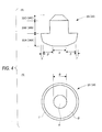
- the first contact 33 and the second contact 34 have a specific shape shown in Fig. 4 , respectively.
- the first contact 33 of the embodiment has a roughly inverted T-shape cross-section. Its lower part is a contacting portion 33A, its middle part is a fixing portion 33B for fixing to the contact spring 32, and its upper part is a conical portion 33C whose bottom surface is a part that contacts with the fixing portion 33B, and which makes it easy to insert the first contact 33 into the holes (not shown in the figure) provided at the first contact holding portion 32A and the second contact holding portion 32B when the first contact 33 is fixed to the first contact holding portion 32A and the second contact holding portion 32B.
- the contacting portion 33A is a portion that contacts with and slides on the conductive segments 23 of the first sliding portion 21.
- the contacting portion 33A is configured by a central portion ⁇ which is located at the top of the contacting portion 33A, a peripheral portion ⁇ which is provided around the central portion ⁇ , and an extensional portion ⁇ which is further provided around the peripheral portion ⁇ .
- the central portion ⁇ unlike the arc-shaped cross-section of the conventional contact, has a flat surface in horizontal direction (the left and right direction in Fig. 4(A) ), and the surface is round, as shown in Fig. 4(B) .
- the central portion ⁇ is restricted to a size which allows to contact simultaneously no more than two conductive segments 23 even when the conductive segments 23 are moved. Namely, when the central portion ⁇ contacts more conductive segments 23, the resistance value between the first contact 33 and the second contact 34 becomes larger, and the detection precision of the liquid level is effected. Thus, the effects on the detection precision of the liquid level is minimized by restricting the number of the conductive segments 23 that the first contact 33 or the second contact 34 contacts with at the same time to neighboring two.
- a predetermined load is set and given based on the bending amount of the contact spring 32 as a pressing force when the first contact 33 or the second contact 34 contacts with the conductive segments 23.
- the central portion ⁇ is configured by a flat surface, compared with the conventional point-contact ones, it is possible to stabilize and ensure a predetermined contacting area with the conductive segments 23.
- a surface, whose diameter [mm] satisfies the following formulae, is formed as the central portion ⁇ of the contacting portion 33A. That is, as shown in Fig. 6 , in the embodiment, when the width W of a conductive segment 23 is 200 ⁇ m on average, and the interval D between conductive segments 23 is 200 ⁇ m, the diameter ( ⁇ ), which is the contact width of the first contact 33, satisfies the following formula. 0.5 ⁇ ⁇ mm ⁇ 0.7 Preferably, the diameter ( ⁇ ) satisfies the following formula. 0.5 ⁇ ⁇ mm ⁇ 0.6 The processes to obtain the formulae (1) and (2) are described later.
- Each of the conductive segments 23, as shown in Fig. 7(A) has a generally arc-shaped cross-section before the initial sliding stage starts.
- the central portion (top portion) of each of the conductive segments 23 is worn (the amount ⁇ is worn) due to the sliding operation when in use, and a generally flat surface (below, flat surface 23A) is gradually formed.
- the flat surface 23A is expanded gradually (The width w of the flat surface 23A can be expanded to no more than the width W of one conductive segment).
- each of the conductive segments 23 forms the flat surface 23A and the central portions ⁇ of the first contact 33 and the second contact 34 have a shape that satisfies the above formulae (1) or (2), as described later, the wear of the first and second contacts 33 and 34 and the conductive segments 23 is lowered due to the contacting thereof, and a desired liquid level detecting precision is maintained.
- the peripheral portion ⁇ has a generally R-like arc-shaped in cross-section, in order to smoothly slide on each of the conductive segments 23 which are roughly pectinate conductive electrodes of the resistance plate 20.
- extensional portion ⁇ is formed to have an inclined cross-section.
- the second contact 34 also has a similar configuration, and performs similar operations on the conductive segments 23.
- the contact spring 32 shown in Fig. 2 has electrical conductivity and resiliency, and the first contact 33 and the second contact 34 are pressed by a resilient force against the conductive segments 23 of the first sliding portion 21 and the second sliding portion 22, respectively. Because of this, the first contact 33 of the sliding body 30 shown in Fig. 1 contacts the conductive segments 23 of the first sliding portion 21 that opposes to the first contact 33 at a certain time, and the second contact 34 contacts the conductive segments of the second sliding portion 22 that opposes to the second contact 34 at a certain time. In this way, the first sliding portion 21 and the second sliding portion 22 are electrically connected to each other via the contact spring 32.
- the float 41 moves upwards and downwards accordingly. Therefore, the contacting position of the sliding body 30 and the conductive segments 23 changes relatively. As a result, because the resistance value of the resistance plate 20 via the sliding body 30 and the conductive segments 23 changes, the height of the liquid level is detected on the basis of the fluctuation of the voltage output from the output terminals 25A and 25B at the time.
- the wear of the first contact 33 and the second contact 34 due to the contacting with the conductive segments 23 is lowered, in comparison with the point contacting of the conventional arc shape, by the stabilized pressure towards the conductive segments 23 and the surface contacting with the conductive segments 23, and predetermined liquid level detecting precision is maintained from the initial sliding stage.
- the distal end of the conventional contact is formed to have a generally R-like cross-section, although it is possible for the contact to incline by means of the contact spring, if a tiny insulating foreign object P is hold at the position of the point contact, the conduction of the contact and the conductive segment is cut off, and there is a possibility of having great influence on liquid level measurement.
- the conventional contact has a R-shaped cross-section
- the slip of the contact in the sliding direction was easy to occur due to the sliding operation of the contact with the R-shaped cross-section.
- the contacting point and the contact area were offset by the movement due to the slid of the contact from the original contacting positions, and positions changed.
- a strongly non-linear relationship existed in the range of the flat surface of each of the conductive segments, and error may be generated in liquid level measurement.
- the central portions ⁇ of the contacting portions of the first and second contacts 33, 34 have a flat shape, this kind of trouble can be avoided.
- liquid level detecting apparatus of the embodiment when a flat surface 23A as shown in Fig. 8(B) was formed on the conductive segments 23 with the lapse of use time, even when a similar tiny insulating foreign object P is trapped between the first contact 33 (or the second contact 34) and the conductive segment 23, it is possible that the first contact 33 (or the second contact 34) is ensured to conductively contact with the conductive segment 23 by extremely slight inclination of the first contact 33 (or the second contact 34).
- the change of a contact over time is stabilized by lowering intense wear of the contact in the initial sliding stage and imparting stabilized wear characteristics from the initial stage of sliding.
- the liquid level detecting apparatus including the first contact 33 and the second contact 34 of the invention, and the liquid level detecting apparatus provided with a conventional contact whose distal end contacts with and slides on conductive segments and which has a R-shaped cross-section, the relationship of the number (N) of the sliding times of the contact and the conductive segment and the wear amount of the contact ( ⁇ ; See Fig. 7(B) ) is illustrated.
- the function as shown in Fig. 9 was obtained.
- the horizontal axis is the sliding times
- the vertical axis is the wear amount of the contact (the wear amount from the top portion of the contact towards the contact spring).
- the graph A is shown for the present invention
- the graph B is for the conventional one.
- the diameter ⁇ of the contact it is appreciated from the aforementioned formulae (3) and (4) that it is desirable for the diameter ⁇ of the contact to have a size that satisfies the following formula. 0.5 ⁇ ⁇ mm ⁇ 0.6
- the present invention is not limited to the above embodiment, and suitable modifications, improvements, can be made.
- the material, shape, dimensions, numerical values, form, number, disposition, etc. , of each of the constituent elements of the above embodiment are arbitrary and are not limited so far as the invention can be achieved.
- the central portion ⁇ of the first and second contacts 33 and 34 shown in Fig. 4(B) has a flat surface that has a round shape, it is not particularly limited to the round shape, as long as the relationship of the contacting area [mm 2 ] and the surface pressure [N/mm 2 ] shown in Figs. 10 and 11 is satisfied and the contact does not contact simultaneously with three or more neighboring conductive segments.
Landscapes
- Physics & Mathematics (AREA)
- Fluid Mechanics (AREA)
- General Physics & Mathematics (AREA)
- Engineering & Computer Science (AREA)
- Microelectronics & Electronic Packaging (AREA)
- Level Indicators Using A Float (AREA)
Abstract
Description
- The present invention relates to a contact type liquid level detecting apparatus which measures a remaining amount of fuel by detecting the liquid level, and particularly to a liquid level detecting apparatus that realizes highly reliable liquid level detection.
- Conventionally, it is known that in a liquid level detecting apparatus for detecting a liquid level of a fuel tank of an automobile, in order to detecting the liquid level, the liquid level is converted into a potential difference by making contacts provided at a sliding body slide on a resistance plate with the upward and downward movement of a float moving upward and downward in accordance with the liquid level (see, for example, Patent Document 1).
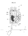
- In a liquid level detecting apparatus, as shown in
Fig. 12 , anarm 120, which is attached to afloat 121, is pivotally moved in accordance with a change of the level of the liquidsurface S. Contacts 111 and 112, which are provided at asliding body 110 that moves integrally with thearm 120, slidingly contact onconductor electrodes resistance plate 130. The liquid level is detected by detecting a voltage value that changes accordingly. In particular, in a liquidlevel detecting apparatus 100, theresistance plate 130 is configured by an Ag/Pd-type conductor circuit portion, which is not illustrated in the figure, sintered on an aluminum substrate. Themetal contacts 111 and 112 of thesliding body 110 contact with and slide on theresistance plate 130. -
-
Patent Document 1JP-A-2009-8535 - In the liquid level detecting apparatus, because the materials that form the conductor circuit portion typically contains glass component other than Ag/Pd, wear of the contact proceeds rapidly especially due to friction with the conductor circuit portion. On the one hand, the
contacts 111 and 112 contact with theconductor electrodes resistance plate 130 as thecontacts 111 and 112 are pushed bycontact springs contacts 111 and 112 that contact with theconductor electrodes contacts 111 and 112 contact with theconductor electrodes contacts 111 and 112 and theconductor electrodes - In view of the above facts, it is desired to decrease the pressure applied to the contacts when the contacts start to slidingly contact onto the above-mentioned conductor electrodes for a while (initial sliding stage in which the contacts repeat the sliding 100,000 times), so as to lower the wear when the contacts slidingly contact onto the conductor electrodes.
- The present invention is made in view of the above mentioned facts. An object of the invention is to provide a liquid level detecting apparatus that realizes highly reliable liquid level detection all the time, wherein the change of a contact over time is stabilized by lowering intense wear of the contact in the initial sliding stage and imparting stabilized wear characteristics from the initial stage of sliding.
- In order to achieve the above object, a liquid level detecting apparatus includes following features (1) to (6).
- (1) There is provided a liquid level detecting apparatus, comprising
a resistance plate that has a plurality of conductive segments provided on an insulating substrate, and a resistor electrically connected with the plurality of conductive segments; and
a sliding body that has a contact which contacts with the plurality of conductive segments, and slides on the plurality of conductive segments in accordance with change of a level of a liquid surface,
wherein the contact of the sliding body has a flat top which contacts with the conductive segments and comes into surface contact with top portions of the plurality of conductive segments when the contact slides on the plurality of conductive segments. - (2) In the liquid level detecting apparatus according to the above mentioned (1), the plurality of conductive segments are provided on the insulating substrate at approximately equal intervals; and the top portion of the contact has such a shape that the contact comes into contact with no more than two neighboring conductive segments when the contact slides on the plurality of conductive segments.
- (3) In the liquid level detecting apparatus according to the above mentioned (2), the top portion of the contact has round shape, and the diameter ϕ of the top portion satisfies 0.5< ϕ [mm] <0.6, when the width W of the conductive segment is 200 [µm], and the interval D of the neighboring conductive segments is 200 [µm].
- (4) In the liquid level detecting apparatus according to the above mentioned (2), the top portion of the contact has round shape, and the diameter ϕ of the top portion in an initial sliding stage satisfies 0.5< ϕ [mm] <0.7, when the width W of the conductive segment is 200 [µm], and the interval D of neighboring conductive segments is 200 [µm].
- (5) In the liquid level detecting apparatus according to any one of the above mentioned (1) to (4), top portions of the conductive segments of the resistance plate which come into contact with the contact have flat shape, and come into surface contact with the top portion of the contact when the contact slidingly contacts with the plurality of conductive segments.
- (6) In the liquid level detecting apparatus according to the above mentioned (5), wherein in the initial sliding stage when the contact slides on the plurality of the conductive segments, the top portions of the conductive segments becomes flat shape due to wear with the sliding of the top portion of the contact.
- According to the liquid level detecting apparatus of the above mentioned (1), intense wear of the contact in the initial sliding stage is lowered by making the top portion of the contact that contacts the conductive segments flat. Thus, stabilized wear characteristics is imparted from the initial stage of sliding and the change of a contact over time is stabilized. It is possible to realize highly reliable liquid level detection all the time.
According to the liquid level detecting apparatus of the above mentioned (2), since the top portion of the contact has such a size that the contact does not simultaneously contact three or more neighboring conductive segments, it is possible for the apparatus to maintain a high level of liquid level detecting precision.
According to the liquid level detecting apparatus of the above mentioned (3), since the force per unit area applied to the top portion of the contact decreases greatly, and the contact has such a size that the contact does not simultaneously contact three or more neighboring conductive segments, it is possible to maintain a high level of liquid level detecting precision.
According to the liquid level detecting apparatus of the above mentioned (4), in the initial sliding stage when the top portion of the conductive segments does not become flat, even if the diameter ϕ of the top portion of the contact is less than 0.7 [mm], it is possible that the top portion of the contact have such a size that the contact does not simultaneously contact three or more neighboring conductive segments.
According to the liquid level detecting apparatus of the above mentioned (5), the wear of both the contact and the conductive segments in the initial sliding stage can be greatly lowered by making both the top portion of the contact that contacts with the conductive segments and the top portion of the conductive segments that contact with the contact flat.
According to the liquid level detecting apparatus of the above mentioned (6), although the conductive segments are not specially processed, the top portions of the conductive segments becomes natural and flat by slidingly contacting onto the flat top portion of the contact in the initial sliding stage. As a result, without processing the part which should become the top portions of the conductive segments, the wear of both the contact and the conductive segments after the top portion of the conductive segments has become flat can be greatly lowered. - In the liquid level detecting apparatus of the invention, intense wear of the contact in the initial sliding stage is lowered by making the top portion of the contact which contacts with the conductive segments flat. Thus, stabilized wear characteristics is imparted from the initial stage of sliding and the change of a contact over time is stabilized. It is possible to realize highly reliable liquid level detection all the time.
- The present invention has been briefly described above. Details of the invention will become more apparent by reading the below-described embodiments of the invention with reference to the accompanying drawings.
-
-
Fig. 1 is a plan view showing a liquid level detecting apparatus of an embodiment of the present invention. -
Fig. 2 is a perspective view showing a sliding body inFig. 1 . -
Fig. 3 is a side view of the sliding body. -
Fig. 4A is a side view showing a contact of the invention andFig. 4B is a plan view of the contact. -
Fig. 5A is an explanatory diagram showing the relationship of the contact (diameter ϕ of the contact is 0.3 [mm]) of the invention and conductor pattern of the conductor segments, andFig. 5B is an explanatory diagram showing the relationship of the contact (diameter ϕ of the contact is 0.6 [mm]) of the invention and conductor pattern of the conductor segments. -
Fig. 6 is a VI-VI line section view ofFig. 5 . -
Fig. 7A is a side view for illustrating the shapes of the conductor segments which slidingly contact the contact before the sliding starts andFig. 7B is a side view for illustrating the shapes of the conductor segments which slidingly contact the contact in the initial sliding stage. -
Fig. 8A is a side view for illustrating the contacting state of the conductor segment and the contact of the invention before the sliding starts andFig. 8B is a side view for illustrating the contacting state of the conductor segment and the contact of the invention in the initial sliding stage. -
Fig. 9 is a chart of the relationship of the number of sliding times and the wear amount of the contact, which is obtained when comparison experiment are made by making use of the liquid level detecting apparatuses of the invention and a conventional one. -
Fig. 10 is a table showing the result of inspecting contacting areas and surface pressures for various contact diameters by making use of the liquid level detecting apparatus of the invention. -
Fig. 11 is a chart showing the relationship of the various contact diameters and the surface pressures [N/mm2] shown inFig. 10 . -
Fig. 12 is a plan view showing a conventional liquid level detecting apparatus. - Next, the embodiments of the invention will be described in detail with reference to the accompanying drawings.
Fig. 1 is a plan view showing a liquid level detecting apparatus of an embodiment of the present invention.Fig. 2 is a perspective view showing a sliding body inFig. 1 .Fig. 3 is a side view of the sliding body.Fig. 4A is a side view showing a contact of the invention andFig. 4B is a plan view of the contact.Fig. 5A is an explanatory diagram showing the relationship of the contact (diameter ϕ of the contact is 0.3 [mm]) of the invention and conductor pattern of the conductor segments, andFig. 5B is an explanatory diagram showing the relationship of the contact (diameter ϕ of the contact is 0.6 [mm]) of the invention and conductor pattern of the conductor segments.Fig. 6 is a VI-VI line section view ofFig. 5 .Figs. 7A and 7B are side views for illustrating the shapes of the conductor segments which slidingly contact the contact before the sliding starts and in the initial sliding stage, respectively.Figs. 8A and 8B are side views for illustrating the contacting state of the conductor segment and the contact of the invention before the sliding starts and in the initial sliding stage, respectively.Fig. 9 is a chart of the relationship of the number of sliding times and the wear amount of the contact, which is obtained when comparison experiment are made by making use of the liquid level detecting apparatuses of the invention and a conventional one.Fig. 10 is a table showing the result of inspecting contacting areas and surface pressures for various contact diameters by making use of the liquid level detecting apparatus of the invention.Fig. 11 is a chart showing the relationship of the various contact diameters and the surface pressures [N/mm2] shown inFig. 10 . -
Fig. 1 shows a liquidlevel detecting apparatus 1 according to the invention. The liquidlevel detecting apparatus 1 is mounted on an automobile in order to detect a height of a liquid surface S of liquid (fuel) L within a fuel tank outside the figure. The liquidlevel detecting apparatus 1 includes aframe 10, aresistance plate 20, a slidingbody 30 and afloat arm 40. Afloat 41, which moves upward and downward in accordance with a change of the level of the liquid surface S of liquid (fuel) L inside the fuel tank, is supported integrally at a distal end of thefloat arm 40. - The
resistance plate 20 and the slidingbody 30 are provided in theframe 10. The slidingbody 30 slides on aconductive pattern 20B (described later) of theresistance plate 20 in conjunction with the rotation of thefloat arm 40. - The
conductive pattern 20B, made of silver palladium (AgPd) which has excellent electrical conductivity and also is excellent in deterioration resistance and corrosion resistance, is provided on theresistance plate 20. Theconductive pattern 20B includes an arc-shaped first slidingportion 21 and an arc-shaped second slidingportion 22 that are formed on an insulatingsubstrate 20A. - In the first sliding
portion 21,conductive segments 23, having roughly pectinate, are arranged at certain intervals in a sliding direction of the slidingbody 30, and an arc-shapedresistor 24 is formed on theconductive segments 23. Theresistor 24 is a resistance layer made of ruthenium oxide which is excellent in sulfur resistance and is less liable to be deteriorated and corroded by electrolysis even when it is exposed to an electrolyte such as ethanol and methanol. Adjacentconductive segments 23 are connected together via theresistor 24, acontact spring 32, afirst contact 33 and a second contact 34 (thecontact spring 32, thefirst contact 33 and thesecond contact 34 will be described later). The first slidingportion 21 is electrically connected tooutput terminal 25A. - In the second sliding
portion 22,conductive segments 23, havingroughly pectinate, are arranged at certain intervals in a sliding direction of the slidingbody 30, and the arc-shaped second slidingportion 22 is formed by conductive materials (silver palladium). The second slidingportion 22 is electrically connected to 25B. - The sliding
body 30 has, as shown inFigs. 2 and 3 , anarm holder 31, acontact spring 32, afirst contact 33 and asecond contact 34 that are fixed to one end of thecontact spring 32. - The
arm holder 31 is formed to be roughly U-shaped when viewed from the side (seeFigs. 2 and 3 ). Anupper holding portion 31A and alower holding portion 31B are formed to be parallel to each other, and are interconnected by an interconnectingportion 31C. Thearm holder 31 of the embodiment is formed by injection molding synthetic resin. - A
shaft hole 311 for the passage of the proximal end side of thefloat arm 40 therethrough is formed through theupper holding portion 31A and thelower holding portion 31B (SeeFig. 2 ). Furthermore, the proximal end side of thefloat arm 40 is bent in a vertical direction orthogonal to the paper surface inFig. 1 , and the proximal end side is inserted through theshaft hole 311. Further, a pair ofside walls 312 is set on theupper holding portion 31A, and thefloat arm 40 passing through theshaft hole 311 is held between the pair ofside walls 312. Therefore, the arm holder 31 (the sliding body 30) is pivotally moved together with thefloat arm 40 in accordance with a change of the level of the liquid surface S. Thefloat arm 40 of the embodiment is formed by bending a stainless steel wire into a predetermined shape. - The
contact spring 32, as shown inFig. 2 , is formed by a thin sheet made of stainless steel having high corrosion resistance. A firstcontact holding portion 32A and a secondcontact holding portion 32B that are roughly V-shaped are formed to be parallel to each other. The firstcontact holding portion 32A and the secondcontact holding portion 32B are connected by aproximal end portion 32C (SeeFig. 3 ) such that the firstcontact holding portion 32A and the secondcontact holding portion 32B are electrically connected together. Theproximal end portion 32C is fixed to theupper holding portion 31A of thearm holder 31 by insertion molding. - The
first contact 33 for sliding on the first slidingportion 21 is fixed to the distal end of the firstcontact holding portion 32A, and thesecond contact 34 for sliding on the second slidingportion 22 is fixed to the distal end of the secondcontact holding portion 32B. Thefirst contact 33 and thesecond contact 34 are made of gold or gold alloy. Or thefirst contact 33 and thesecond contact 34 may be made of copper or copper alloy, in which case gold or gold alloy is plated on the surface of the copper or copper alloy substrate. - The
first contact 33 and thesecond contact 34, as mentioned above, are fixed to the firstcontact holding portion 32A and the secondcontact holding portion 32B of thecontact spring 32. In particular, thefirst contact 33 and thesecond contact 34 is fitted and fixed in holes (not shown in the figure) provided at distal ends of the firstcontact holding portion 32A and the secondcontact holding portion 32B. Thefirst contact 33 and thesecond contact 34 have a specific shape shown inFig. 4 , respectively. - That is, the
first contact 33 of the embodiment has a roughly inverted T-shape cross-section. Its lower part is a contactingportion 33A, its middle part is a fixingportion 33B for fixing to thecontact spring 32, and its upper part is aconical portion 33C whose bottom surface is a part that contacts with the fixingportion 33B, and which makes it easy to insert thefirst contact 33 into the holes (not shown in the figure) provided at the firstcontact holding portion 32A and the secondcontact holding portion 32B when thefirst contact 33 is fixed to the firstcontact holding portion 32A and the secondcontact holding portion 32B. - The contacting
portion 33A is a portion that contacts with and slides on theconductive segments 23 of the first slidingportion 21. The contactingportion 33A is configured by a central portion α which is located at the top of the contactingportion 33A, a peripheral portion β which is provided around the central portion α, and an extensional portion γ which is further provided around the peripheral portion β. - The central portion α, unlike the arc-shaped cross-section of the conventional contact, has a flat surface in horizontal direction (the left and right direction in
Fig. 4(A) ), and the surface is round, as shown inFig. 4(B) . In addition, the central portion α, as shown inFigs. 5(A) and 5(B) , is restricted to a size which allows to contact simultaneously no more than twoconductive segments 23 even when theconductive segments 23 are moved. Namely, when the central portion α contacts moreconductive segments 23, the resistance value between thefirst contact 33 and thesecond contact 34 becomes larger, and the detection precision of the liquid level is effected. Thus, the effects on the detection precision of the liquid level is minimized by restricting the number of theconductive segments 23 that thefirst contact 33 or thesecond contact 34 contacts with at the same time to neighboring two. - In addition, a predetermined load is set and given based on the bending amount of the
contact spring 32 as a pressing force when thefirst contact 33 or thesecond contact 34 contacts with theconductive segments 23. In the present invention, since the central portion α is configured by a flat surface, compared with the conventional point-contact ones, it is possible to stabilize and ensure a predetermined contacting area with theconductive segments 23. Thus, it is possible to press thefirst contact 33 or thesecond contact 34 against theconductive segments 23 at desired surface pressure. - In the
first contact 33 of the embodiment, a surface, whose diameter [mm] satisfies the following formulae, is formed as the central portion α of the contactingportion 33A. That is, as shown inFig. 6 , in the embodiment, when the width W of aconductive segment 23 is 200µm on average, and the interval D betweenconductive segments 23 is 200µm, the diameter (ϕ), which is the contact width of thefirst contact 33, satisfies the following formula.
Preferably, the diameter (ϕ) satisfies the following formula.
The processes to obtain the formulae (1) and (2) are described later. - Each of the
conductive segments 23, as shown inFig. 7(A) , has a generally arc-shaped cross-section before the initial sliding stage starts. As shown inFig. 7(B) , the central portion (top portion) of each of theconductive segments 23 is worn (the amount δ is worn) due to the sliding operation when in use, and a generally flat surface (below,flat surface 23A) is gradually formed. Theflat surface 23A is expanded gradually (The width w of theflat surface 23A can be expanded to no more than the width W of one conductive segment). Thus, when the top portion of each of theconductive segments 23 forms theflat surface 23A and the central portions α of thefirst contact 33 and thesecond contact 34 have a shape that satisfies the above formulae (1) or (2), as described later, the wear of the first andsecond contacts conductive segments 23 is lowered due to the contacting thereof, and a desired liquid level detecting precision is maintained. - As shown in
Fig. 4 , the peripheral portion β has a generally R-like arc-shaped in cross-section, in order to smoothly slide on each of theconductive segments 23 which are roughly pectinate conductive electrodes of theresistance plate 20. - In addition, the extensional portion γ is formed to have an inclined cross-section.
- Furthermore, although the
first contact 33 is described mainly, thesecond contact 34 also has a similar configuration, and performs similar operations on theconductive segments 23. - Next, the effects of the embodiment are described.
In the liquid level detecting apparatus of the embodiment, thecontact spring 32 shown inFig. 2 has electrical conductivity and resiliency, and thefirst contact 33 and thesecond contact 34 are pressed by a resilient force against theconductive segments 23 of the first slidingportion 21 and the second slidingportion 22, respectively. Because of this, thefirst contact 33 of the slidingbody 30 shown inFig. 1 contacts theconductive segments 23 of the first slidingportion 21 that opposes to thefirst contact 33 at a certain time, and thesecond contact 34 contacts the conductive segments of the second slidingportion 22 that opposes to thesecond contact 34 at a certain time. In this way, the first slidingportion 21 and the second slidingportion 22 are electrically connected to each other via thecontact spring 32. - When the height of the liquid level changes, the
float 41 moves upwards and downwards accordingly. Therefore, the contacting position of the slidingbody 30 and theconductive segments 23 changes relatively. As a result, because the resistance value of theresistance plate 20 via the slidingbody 30 and theconductive segments 23 changes, the height of the liquid level is detected on the basis of the fluctuation of the voltage output from theoutput terminals - Particularly, according to the embodiment, because the central portions of the
first contact 33 and thesecond contact 34 have a flat surface, the wear of thefirst contact 33 and thesecond contact 34 due to the contacting with theconductive segments 23 is lowered, in comparison with the point contacting of the conventional arc shape, by the stabilized pressure towards theconductive segments 23 and the surface contacting with theconductive segments 23, and predetermined liquid level detecting precision is maintained from the initial sliding stage. - For example, as shown in
Fig. 8(A) , in the initial sliding stage, even when a tiny insulating foreign object P is trapped between the first contact 33 (or the second contact 34) and theconductive segment 23, it is possible that the first contact 33 (or the second contact 34) are ensured to conductively contacts with theconductive segment 23 by slight inclination of the first contact 33 (or the second contact 34) attached to thecontact spring 32A (or 32B) which possesses flexibility. On the one hand, since the distal end of the conventional contact is formed to have a generally R-like cross-section, although it is possible for the contact to incline by means of the contact spring, if a tiny insulating foreign object P is hold at the position of the point contact, the conduction of the contact and the conductive segment is cut off, and there is a possibility of having great influence on liquid level measurement. - Particularly, since the conventional contact has a R-shaped cross-section, in the contacting operation with the roughly pectinate conductive segments, the slip of the contact in the sliding direction was easy to occur due to the sliding operation of the contact with the R-shaped cross-section. As a result, the contacting point and the contact area were offset by the movement due to the slid of the contact from the original contacting positions, and positions changed. As a result, there was a possibility that a strongly non-linear relationship existed in the range of the flat surface of each of the conductive segments, and error may be generated in liquid level measurement. On the other hand, in the present embodiment, since the central portions α of the contacting portions of the first and
second contacts flat surface 23A as shown inFig. 8(B) was formed on theconductive segments 23 with the lapse of use time, even when a similar tiny insulating foreign object P is trapped between the first contact 33 (or the second contact 34) and theconductive segment 23, it is possible that the first contact 33 (or the second contact 34) is ensured to conductively contact with theconductive segment 23 by extremely slight inclination of the first contact 33 (or the second contact 34). - Thus, according to the liquid level detecting apparatus of the embodiment, the change of a contact over time is stabilized by lowering intense wear of the contact in the initial sliding stage and imparting stabilized wear characteristics from the initial stage of sliding. Thus, it is possible to realize highly reliable liquid level detection all the time.
- Next, with respect to the liquid level detecting apparatus including the
first contact 33 and thesecond contact 34 of the invention, and the liquid level detecting apparatus provided with a conventional contact whose distal end contacts with and slides on conductive segments and which has a R-shaped cross-section, the relationship of the number (N) of the sliding times of the contact and the conductive segment and the wear amount of the contact (δ; SeeFig. 7(B) ) is illustrated. - As the result of testing the relationship of the number (N) of the sliding times of the contact and the conductive segment and the wear amount of the contact (δ), the function as shown in
Fig. 9 was obtained. InFig. 9 , the horizontal axis is the sliding times, and the vertical axis is the wear amount of the contact (the wear amount from the top portion of the contact towards the contact spring). Further, the graph A is shown for the present invention, and the graph B is for the conventional one.
Therefore, it is appreciated that, compared with the conventional liquid level detecting apparatus whose contact has a generally arc-shaped cross-section, since the central portion of thefirst contact 33 and thesecond contact 34 of the liquid level detecting apparatus of the present invention has a flat surface, these contacts would not be sharply worn in the initial sliding stage (before 100,000 times of sliding). In other words, a linear graph is obtained as the correlation in the present invention. Because the wear over time is almost the same despite the sliding times, stabilized contacting and sliding operations can be obtained. - On the other hand, for the conventional liquid level detecting apparatus, it is appreciated that the contact is sharply worn in the initial sliding stage (before 100,000 times of sliding). Because of this, the contact and sliding operation become unstable, the detecting precision in the initial sliding stage is low, and it was verified that accurate liquid level detection is impossible.
- Next, in order to specify optimum diameter of the
first contact 33 or thesecond contact 34 of the liquid level detecting apparatus of the invention, experiments are made on the relationship of the diameter ϕ [mm] of the contact that contacts with theconductive segments 23, the contacting area [mm2] of the contact in which the contact contacts with theconductive segments 23, and the surface pressure [N/mm2] which is force per unit area applied to the contact that depends on the contact area, to find out their minimum values (MIN), maximum values (MAX), and mean values (AVE), respectively. Then, the results shown inFig. 10 were obtained. Further, in order to find out the correlation of the diameter [mm] of the contact and the surface pressure [N/mm2], the graph inFig. 11 , which shows their correlation clearly, was drawn up on the basis of the experimental data inFig. 10 . - Therefore, when the diameter ϕ of the contact is 0.3 to 0.5 [mm], it can be seen that the surface pressure decreases sharply from the relationship of the contacting area of the contact with the conductive segment and the surface pressure in
Figs. 10 and11 . On the one hand, when the diameter (ϕ) of the contact exceeds 0.5 [mm], the surface pressure does not decrease significantly, but decreases gradually to near 0. Therefore, in order to decrease the wear of the contact, it is found that it is desirable to satisfy the following relationship.
- However, when the value of ϕ is increased in order to decrease the surface pressure, it becomes possible that the contact contacts simultaneously with three or more neighboring conductive segments. In this case, the decrease of the detection precision occurs with the increase of the resistance value. In addition, it is verified that when the contact contacts simultaneously with no more than two neighboring conductive segments, detection precision is not a problem.
- Therefore, as shown in
Fig. 7 , when the width W of one conductive segment is 200 [µm], and the interval D of neighboring conductive segments is 200 [µm], it is found that it is desirable for the diameter ϕ of the contact to satisfy the next formula.
- Therefore, in the embodiment, it is appreciated from the aforementioned formulae (3) and (4) that it is desirable for the diameter ϕ of the contact to have a size that satisfies the following formula.

- Furthermore, in each pattern of the conductor segments, as shown in
Fig. 7(B) , when aflat surface 23A is formed and the width w of theflat surface 23A reaches 200 [µm], to avoid that the above contact contacts simultaneously to three or more neighboring conductive segments, it is necessary for the diameter ϕ of the contact to be less than 0.6 [mm]. On the one hand, when the width w of theflat surface 23A is less than 200 [µm], it is also possible that the diameter ϕ of the contact is larger than 0.6 [mm]. Thus, when it is considered that aflat surface 23A has not been formed in the initial sliding stage, it is also allowable that the diameter ϕ of the contact satisfies the following formula.
- The present invention is not limited to the above embodiment, and suitable modifications, improvements, can be made. Furthermore, the material, shape, dimensions, numerical values, form, number, disposition, etc. , of each of the constituent elements of the above embodiment are arbitrary and are not limited so far as the invention can be achieved. For example, although the central portion α of the first and
second contacts Fig. 4(B) has a flat surface that has a round shape, it is not particularly limited to the round shape, as long as the relationship of the contacting area [mm2] and the surface pressure [N/mm2] shown inFigs. 10 and11 is satisfied and the contact does not contact simultaneously with three or more neighboring conductive segments. - Although the present invention is described in detail with reference to the embodiments, it is apparent that various modifications and amendments may be made by those skilled in the art without departing from the spirit and scope of the invention.
- This application is based on the Japanese patent application (patent application
2009-064364 -
- 1
- liquid level detecting apparatus
- 10
- frame
- 20
- resistance plate
- 20A
- insulating substrate
- 20B
- conductive pattern
- 21
- first sliding portion
- 22
- second sliding portion
- 23
- conductive segment
- 23A
- flat surface
- 24
- resistor
- 25A, 25B
- output terminal
- 30
- sliding body
- 31
- arm holder
- 31A
- upper holding portion
- 31B
- lower holding portion
- 31C
- interconnecting portion
- 311
- shaft hole
- 32
- contact spring
- 32A
- first contact holding portion
- 32B
- second contact holding portion
- 32C
- proximal end portion
- 33
- first contact
- 33A
- contacting portion
- 33B
- fixing portion
- 34
- second contact
- 41
- float
- 40
- float arm
- L
- fuel
- P
- insulating foreign object
- S
- liquid surface
- α
- central portion (flat portion)
- β
- peripheral portion
- γ
- extensional portion
- ϕ
- diameter (contacting width)
Claims (6)
- A liquid level detecting apparatus, comprising
a resistance plate that has a plurality of conductive segments provided on an insulating substrate, and a resistor electrically connected with the plurality of conductive segments; and
a sliding body that has a contact which contacts with the plurality of conductive segments, and slides on the plurality of conductive segments in accordance with change of a level of a liquid surface,
wherein the contact of the sliding body has a flat top which contacts with the conductive segments and comes into surface contact with top portions of the plurality of conductive segments when the contact slides on the plurality of conductive segments. - The liquid level detecting apparatus according to claim 1, wherein the plurality of conductive segments are provided on the insulating substrate at approximately equal intervals; and
wherein the top portion of the contact has such a shape that the contact comes into contact with no more than two neighboring conductive segments when the contact slides on the plurality of conductive segments. - The liquid level detecting apparatus according to claim 2, wherein the top portion of the contact has round shape, and the diameter ϕ of the top portion satisfies 0.5< ϕ [mm] <0.6, when the width W of the conductive segment is 200 [µm], and the interval D of the neighboring conductive segments is 200 [µm].
- The liquid level detecting apparatus according to claim 2, wherein the top portion of the contact has round shape, and the diameter ϕ of the top portion in an initial sliding stage satisfies 0.5< ϕ [mm] <0.7, when the width W of the conductive segment is 200 [µm], and the interval D of neighboring conductive segments is 200 [µm].
- The liquid level detecting apparatus according to any one of claims 1 to 4, wherein top portions of the conductive segments of the resistance plate which come into contact with the contact have flat shape, and come into surface contact with the top portion of the contact when the contact slidingly contacts with the plurality of conductive segments.
- The liquid level detecting apparatus according to claim 5, wherein in the initial sliding stage when the contact slides on the plurality of the conductive segments, the top portions of the conductive segments becomes flat shape due to wear with the sliding of the top portion of the contact.
Applications Claiming Priority (2)
| Application Number | Priority Date | Filing Date | Title |
|---|---|---|---|
| JP2009064364A JP5241020B2 (en) | 2009-03-17 | 2009-03-17 | Liquid level detector |
| PCT/JP2010/054463 WO2010107035A1 (en) | 2009-03-17 | 2010-03-16 | Liquid level detector |
Publications (2)
| Publication Number | Publication Date |
|---|---|
| EP2410302A1 true EP2410302A1 (en) | 2012-01-25 |
| EP2410302A4 EP2410302A4 (en) | 2017-12-27 |
Family
ID=42739695
Family Applications (1)
| Application Number | Title | Priority Date | Filing Date |
|---|---|---|---|
| EP10753527.0A Withdrawn EP2410302A4 (en) | 2009-03-17 | 2010-03-16 | Liquid level detector |
Country Status (5)
| Country | Link |
|---|---|
| US (1) | US8746061B2 (en) |
| EP (1) | EP2410302A4 (en) |
| JP (1) | JP5241020B2 (en) |
| CN (1) | CN102356304A (en) |
| WO (1) | WO2010107035A1 (en) |
Cited By (2)
| Publication number | Priority date | Publication date | Assignee | Title |
|---|---|---|---|---|
| WO2018141443A1 (en) * | 2017-02-03 | 2018-08-09 | Robert Bosch Gmbh | Method and device for determining a functional status of a sliding contact of a fill level sensor that moves along a resistance section |
| WO2018224209A1 (en) * | 2017-06-06 | 2018-12-13 | Robert Bosch Gmbh | Variable electric resistor and method for detecting wear on a sliding contact of the variable resistor |
Families Citing this family (5)
| Publication number | Priority date | Publication date | Assignee | Title |
|---|---|---|---|---|
| JP5483277B2 (en) * | 2009-11-09 | 2014-05-07 | 矢崎総業株式会社 | Contact of liquid level detection device and liquid level detection device |
| JP5353953B2 (en) * | 2011-06-03 | 2013-11-27 | 株式会社デンソー | Liquid level detection system and liquid level detection device |
| JP6061137B2 (en) * | 2013-01-21 | 2017-01-18 | 日本精機株式会社 | Liquid level detector |
| US10425730B2 (en) * | 2016-04-14 | 2019-09-24 | Harman International Industries, Incorporated | Neural network-based loudspeaker modeling with a deconvolution filter |
| US10634102B2 (en) * | 2018-09-06 | 2020-04-28 | Trico Group, LLC | Fuel pump assembly |
Family Cites Families (13)
| Publication number | Priority date | Publication date | Assignee | Title |
|---|---|---|---|---|
| JP3663296B2 (en) * | 1998-03-26 | 2005-06-22 | カヤバ工業株式会社 | Potentiometer |
| JP2000046632A (en) * | 1998-07-31 | 2000-02-18 | Nippon Seiki Co Ltd | Liquid level detecting device |
| JP2000193512A (en) * | 1998-12-28 | 2000-07-14 | Nippon Seiki Co Ltd | Liquid level detecting device |
| JP3901968B2 (en) * | 2001-08-27 | 2007-04-04 | 矢崎総業株式会社 | Liquid level detector |
| JP2004184097A (en) * | 2002-11-29 | 2004-07-02 | Nippon Seiki Co Ltd | Liquid level detector |
| JP3941710B2 (en) * | 2003-02-20 | 2007-07-04 | 株式会社デンソー | Liquid level detector |
| US6828898B2 (en) * | 2003-04-03 | 2004-12-07 | Cts Corporation | Fuel tank resistor card having improved corrosion resistance |
| US7043982B2 (en) * | 2003-09-26 | 2006-05-16 | Robert Bosch Corporation | Fuel level sending unit and contact button for same |
| JP4405334B2 (en) * | 2004-07-22 | 2010-01-27 | 矢崎総業株式会社 | Liquid level detector |
| JP2006058598A (en) * | 2004-08-20 | 2006-03-02 | Fuji Xerox Co Ltd | Memory tag, process cartridge and image forming apparatus |
| JP2007093472A (en) * | 2005-09-29 | 2007-04-12 | Yazaki Corp | Electrical contact material and sliding liquid level detector |
| JP4832085B2 (en) * | 2006-01-16 | 2011-12-07 | 矢崎総業株式会社 | Sliding liquid level detector |
| JP5078461B2 (en) * | 2007-06-28 | 2012-11-21 | 矢崎総業株式会社 | Liquid level detector |
-
2009
- 2009-03-17 JP JP2009064364A patent/JP5241020B2/en not_active Expired - Fee Related
-
2010
- 2010-03-16 CN CN201080012488XA patent/CN102356304A/en active Pending
- 2010-03-16 WO PCT/JP2010/054463 patent/WO2010107035A1/en not_active Ceased
- 2010-03-16 US US13/256,747 patent/US8746061B2/en not_active Expired - Fee Related
- 2010-03-16 EP EP10753527.0A patent/EP2410302A4/en not_active Withdrawn
Non-Patent Citations (1)
| Title |
|---|
| See references of WO2010107035A1 * |
Cited By (2)
| Publication number | Priority date | Publication date | Assignee | Title |
|---|---|---|---|---|
| WO2018141443A1 (en) * | 2017-02-03 | 2018-08-09 | Robert Bosch Gmbh | Method and device for determining a functional status of a sliding contact of a fill level sensor that moves along a resistance section |
| WO2018224209A1 (en) * | 2017-06-06 | 2018-12-13 | Robert Bosch Gmbh | Variable electric resistor and method for detecting wear on a sliding contact of the variable resistor |
Also Published As
| Publication number | Publication date |
|---|---|
| US20120000282A1 (en) | 2012-01-05 |
| JP2010217002A (en) | 2010-09-30 |
| WO2010107035A1 (en) | 2010-09-23 |
| CN102356304A (en) | 2012-02-15 |
| EP2410302A4 (en) | 2017-12-27 |
| JP5241020B2 (en) | 2013-07-17 |
| US8746061B2 (en) | 2014-06-10 |
Similar Documents
| Publication | Publication Date | Title |
|---|---|---|
| US8746061B2 (en) | Liquid level detecting apparatus | |
| EP2013617B1 (en) | Biological testing system | |
| KR101860923B1 (en) | Contacts for testing a semiconductor device, and socket device | |
| US6985068B2 (en) | Fuel tank resistor card having improved corrosion resistance | |
| US20140065893A1 (en) | Compliant Electrical Contact | |
| US7752912B2 (en) | Sliding fluid level-detecting device | |
| US8671751B2 (en) | Liquid level detecting apparatus | |
| US7111510B2 (en) | Liquid level detection device | |
| US4701702A (en) | Contact pin having a spring under tension | |
| US20090000376A1 (en) | Liquid level detecting apparatus | |
| KR102165661B1 (en) | Socket for electrical parts and manufacturing method thereof | |
| US8044698B2 (en) | Liquid level detection apparatus | |
| CN1146730C (en) | Easy-to-use contact device | |
| EP1630530B1 (en) | Liquid level detector | |
| KR102757925B1 (en) | Test contactor | |
| CN107870018B (en) | Fuel level sensing device for fuel tank | |
| CN224123544U (en) | Sensing connector | |
| EP3035356A1 (en) | Electrical switches and methods | |
| CN220626595U (en) | Test structure and test device | |
| CN110672184A (en) | Liquid level sensor of vehicle box | |
| CN221039322U (en) | Test structure and test device | |
| KR920000564B1 (en) | Weighting sensor | |
| JPH09232481A (en) | Connector for electronic part | |
| JP2013088353A (en) | Liquid level detection apparatus using slide resistance type sensor | |
| JP3908230B2 (en) | probe |
Legal Events
| Date | Code | Title | Description |
|---|---|---|---|
| PUAI | Public reference made under article 153(3) epc to a published international application that has entered the european phase |
Free format text: ORIGINAL CODE: 0009012 |
|
| 17P | Request for examination filed |
Effective date: 20110916 |
|
| AK | Designated contracting states |
Kind code of ref document: A1 Designated state(s): AT BE BG CH CY CZ DE DK EE ES FI FR GB GR HR HU IE IS IT LI LT LU LV MC MK MT NL NO PL PT RO SE SI SK SM TR |
|
| DAX | Request for extension of the european patent (deleted) | ||
| RA4 | Supplementary search report drawn up and despatched (corrected) |
Effective date: 20171128 |
|
| RIC1 | Information provided on ipc code assigned before grant |
Ipc: G01F 23/36 20060101AFI20171122BHEP Ipc: H01C 10/32 20060101ALI20171122BHEP |
|
| 17Q | First examination report despatched |
Effective date: 20180522 |
|
| STAA | Information on the status of an ep patent application or granted ep patent |
Free format text: STATUS: THE APPLICATION HAS BEEN WITHDRAWN |
|
| 18W | Application withdrawn |
Effective date: 20180731 |