EP2410297A2 - Systems and methods for measuring angular motion - Google Patents
Systems and methods for measuring angular motion Download PDFInfo
- Publication number
- EP2410297A2 EP2410297A2 EP11250653A EP11250653A EP2410297A2 EP 2410297 A2 EP2410297 A2 EP 2410297A2 EP 11250653 A EP11250653 A EP 11250653A EP 11250653 A EP11250653 A EP 11250653A EP 2410297 A2 EP2410297 A2 EP 2410297A2
- Authority
- EP
- European Patent Office
- Prior art keywords
- sensor
- nut
- tapered surface
- sensor component
- sensors
- Prior art date
- Legal status (The legal status is an assumption and is not a legal conclusion. Google has not performed a legal analysis and makes no representation as to the accuracy of the status listed.)
- Granted
Links
Images



Classifications
-
- G—PHYSICS
- G01—MEASURING; TESTING
- G01D—MEASURING NOT SPECIALLY ADAPTED FOR A SPECIFIC VARIABLE; ARRANGEMENTS FOR MEASURING TWO OR MORE VARIABLES NOT COVERED IN A SINGLE OTHER SUBCLASS; TARIFF METERING APPARATUS; MEASURING OR TESTING NOT OTHERWISE PROVIDED FOR
- G01D5/00—Mechanical means for transferring the output of a sensing member; Means for converting the output of a sensing member to another variable where the form or nature of the sensing member does not constrain the means for converting; Transducers not specially adapted for a specific variable
- G01D5/12—Mechanical means for transferring the output of a sensing member; Means for converting the output of a sensing member to another variable where the form or nature of the sensing member does not constrain the means for converting; Transducers not specially adapted for a specific variable using electric or magnetic means
- G01D5/14—Mechanical means for transferring the output of a sensing member; Means for converting the output of a sensing member to another variable where the form or nature of the sensing member does not constrain the means for converting; Transducers not specially adapted for a specific variable using electric or magnetic means influencing the magnitude of a current or voltage
- G01D5/20—Mechanical means for transferring the output of a sensing member; Means for converting the output of a sensing member to another variable where the form or nature of the sensing member does not constrain the means for converting; Transducers not specially adapted for a specific variable using electric or magnetic means influencing the magnitude of a current or voltage by varying inductance, e.g. by a movable armature
-
- B—PERFORMING OPERATIONS; TRANSPORTING
- B64—AIRCRAFT; AVIATION; COSMONAUTICS
- B64C—AEROPLANES; HELICOPTERS
- B64C25/00—Alighting gear
- B64C25/02—Undercarriages
- B64C25/08—Undercarriages non-fixed, e.g. jettisonable
- B64C25/10—Undercarriages non-fixed, e.g. jettisonable retractable, foldable, or the like
- B64C25/18—Operating mechanisms
- B64C25/26—Control or locking systems therefor
- B64C25/28—Control or locking systems therefor with indicating or warning devices
-
- B—PERFORMING OPERATIONS; TRANSPORTING
- B64—AIRCRAFT; AVIATION; COSMONAUTICS
- B64D—EQUIPMENT FOR FITTING IN OR TO AIRCRAFT; FLIGHT SUITS; PARACHUTES; ARRANGEMENT OR MOUNTING OF POWER PLANTS OR PROPULSION TRANSMISSIONS IN AIRCRAFT
- B64D45/00—Aircraft indicators or protectors not otherwise provided for
- B64D2045/008—Devices for detecting or indicating hard landing
Definitions
- the present invention provides a system for monitoring landing gear position.
- the present invention also provides a system for measuring strut extension by measuring rotation of the torque linkage which occurs as the strut is extended.
- An example rotation position sensor includes a hub mount that locks within a shaft of a joint between two rotatably attached parts, a first sensor component that is attached to the hub mount, and a second sensor component that is attached to the rotatably attached part that does not rotate with the joint of the shaft.
- the hub mount includes a nut that has a partially tapered surface and a threaded cavity. The nut is secured within the sha8.
- the hub mount also includes a mounting unit that has a partially tapered surface that is in opposition to the partially tapered surface of the nut. A fastener is received within the threaded cavity far securing the hub mount to the nut.
- the partially tapered surface of the nut is an outer surface and the partially tapered surface of the mounting unit is in inner surface.
- the first sensor component includes a magnetometer and the second sensor component includes one or more magnets.
- the first sensor component includes one or more inductor sensors and the second sensor component includes one or more devices that cause a change in an inductance value of the one or more inductor sensors as the joint rotates.
- FIGURE 1 is a perspective view of a landing gear assembly
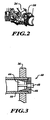
- FIGURE 2 is a perspective view of a link joint of the assembly shown in FIGURE 1 ;
- FIGURE 3 is a cross-sectional view of a joint mounting component formed in accordance with the present invention.
- FIGURE 4 is a cross-sectional view of a monitoring device formed in accordance with an embodiment of the present invention.
- FIGURES 5-1, 5-2 illustrate magnetometer used in the device shown in FIGURE 4 ;
- FIGURE 6 illustrate a geometrical relationship of the strut assembly
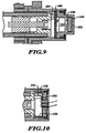
- FIGURES 7-10 are cross-sectional views of various monitoring device formed in accordance with an alternate embodiments of the present invention.
- FIGURES 1 and 2 illustrate a landing gear structure 20 having a torque linkage 24.
- the torque linkage 24 restrains a piston 22 from rotating within a strut 23 under a torque MV.
- the torque linkage 24 is designed to flex as the piston 22 is telescoped into the strut 23.
- the present invention is a device that mounts within a link joint shaft 30 for sensing rotation of the link joint shaft 30 to determine position of the piston 22 relative to the strut 23 (i.e., amount of piston extension).
- FIGURE 3 shows a hub assembly 40 mounted in the joint shaft 30.
- the hub assembly 40 includes a shaft nut 44, a bolt 48 end a tapered looking hub 46 which has independent axial fingers formed by slitting the hub radially every 20 degrees or more or less often.
- the shaft nut 44, the bolt 48 and the tapered looking hub 46 are loosely assembled with the bolt 48 inserted through the locking hub 46 and a threaded cavity of the nut 44. This loose assembly is inserted into the shaft 30.
- the tapered locking hub 46 securely wedges between the outer circumference of the nut 44 and the inner wall of the shaft 30.
- An outer flange of the tapered locking hub 46 may come in contact with an outer edge of the shaft 30.
- Other configurations between the nut 44 and the hub 46 may be used.
- a magnetometer angle sensor 60 is mounted to the link joint shaft 30 via the hub assembly 40.
- the sensor 60 includes thin magnets 82, 84, and a magnetoresistive magnetometer 80 attached to a circuit card 88.
- the circuit card 88 is attached (bolted, epoxy, or other attachment device) to the hub assembly 40.
- the magnetometer 80 is positioned on the circuit card 88 such that it fits between the two magnets 82, 84 that are attached to the stationary strut 25 via a frame device 86.
- the magnets 82, 84, are opposed to each other, presenting opposite north/south poles to the magnetometer 80.
- the magnetometer 80 has magnetoresistive elements in a Wheatstone bridge configuration.
- An example magnetometer device is produced by MEAS Deutschland GmbH, which incorporates two magnetoresistive bridges at 45 degrees to each other as described above. This device is mounted on the circuit card 88 and position in the center of the flux field between magnets 84.
- support electronics are applied to the circuit board hosting the magnetometer 80.
- the support electronics may include a battery and/or a local wireless transmitter that is either integral to the magnetometer 80 or wired to a separate host module elsewhere in the system.
- a sensor 160 extends beyond the end of the shaft 30.
- the sensor 160 includes a sensing element 164 that is mounted on the hub assembly 40.
- a two-part metal shield 150 protects the sensor 160 from contamination.
- the shield 150 includes a first half 152 that attaches to a fixed portion of the strut 25.
- the shield 150 includes a second half 162 that attaches to the hub assembly 40 using lugs or screws or other fastening means 166.
- the second half 162 and the shaft 30 move with the torque linkage 24 as it rotates.
- a securing device 172 is bonded or integral with the first half 152.
- the securing device 172 is secured in various ways to the strut 25 depending on the strut configuration.
- the halves 152, 162 come in contact to provide a seal.
- a puck 154 is mounted to the first half of the shield 152.
- the sensing element 164 includes one or more antennae (an example is produced by Sagentia Ltd., UK), which are mounted to the hub assembly 40.
- the one or more antennae face the puck 154. Rotational position is sensed by mutual inductance between the puck 154 and the antennae.
- the antennae include a receive circuit and a set of current-carrying conductor (i.e., a transmit circuit) that produce an alternating electromagnetic field.
- the receive circuit is electrically insulated from the transmit circuit. Signals induced in the receive circuits may be electronically decoded using various methods in order to provide information about the position of the torque link/shaft.
- the puck 154 includes a passive resonant circuit having a resonant frequency in the range of 1-3 MHz - other frequencies may be used.
- the puck 154 includes a capacitor mounted on a printed circuit board whose conductors are patterned in such a way as to produce an inductor.
- a sending antenna patterned on a circuit board forms a portion of a sensing element 164 that radiates an RF field inducing a current in the puck 154.
- the puck 154 re-radiates a field activating a receive antenna Located on the sensing element 164 from which is derived the position of the puck from which is inferred the rotational angle of the torque link/shaft. Details of this mechanism can be found in U.S. Patent # 7,208,945 owned by Sagentia Ltd.
- the locations of the puck 154 and the antenna board 164 may be reversed.
- the inductive sensor is enclosed within the bushing or shaft of the landing gear in the interest of reducing size and offering protection from flying debris.
- a bushing 210 mounts to the stationary strut (lug) 25 and extends beyond the hub assembly 40.
- the hub assembly 40 receives the inductive puck 204.
- the antenna board 206 is mounted to the bushing 210 or to a retainer 212 which hermetically seals the puck(s) 204 and the antenna board 206.
- the sensor of FIGURE 8 includes a radome 220 that is attached to or part of the stationary bushing 210.
- a battery 224 and a radio circuit 226 are located within the radome 220.
- the radio circuit 226 is in signal communication with the antenna board 206 and an antenna 222.
- the radome 220 is made of a low dielectric material as to not interfere with radio propagation. Various methods of sealing may be employed.
- FIGURE 10 illustrates an embodiment where a flexible antenna 250 that is attached to an inner wall of a portion attached to the strut 25 or a retainer.
- a puck 252 is mounted to a component 256 such that the puck 252 faces the flexible antenna 250 and is attached to the hub assembly 40.
Landscapes
- Engineering & Computer Science (AREA)
- Mechanical Engineering (AREA)
- Aviation & Aerospace Engineering (AREA)
- Physics & Mathematics (AREA)
- General Physics & Mathematics (AREA)
- Measurement Of Length, Angles, Or The Like Using Electric Or Magnetic Means (AREA)
Abstract
Description
- There are presently some devices for monitoring loading of landing gear. Current systems have a low level of accuracy and provide little information on actual stresses in the landing gear structure. A new landing gear overload system is devised. One element of such a system is measurement of strut extension, allowing calculation of loading moment on the strut. Conventional means of measuring strut extension might rely on position sensors which are delicate, expensive, and require significant protection from debris and other environmental factors.
- The present invention provides a system for monitoring landing gear position. The present invention also provides a system for measuring strut extension by measuring rotation of the torque linkage which occurs as the strut is extended.
- An example rotation position sensor includes a hub mount that locks within a shaft of a joint between two rotatably attached parts, a first sensor component that is attached to the hub mount, and a second sensor component that is attached to the rotatably attached part that does not rotate with the joint of the shaft. The hub mount includes a nut that has a partially tapered surface and a threaded cavity. The nut is secured within the sha8. The hub mount also includes a mounting unit that has a partially tapered surface that is in opposition to the partially tapered surface of the nut. A fastener is received within the threaded cavity far securing the hub mount to the nut.
- In one aspect of the invention, the partially tapered surface of the nut is an outer surface and the partially tapered surface of the mounting unit is in inner surface.
- In another aspect of the invention, the first sensor component includes a magnetometer and the second sensor component includes one or more magnets.
- In still another aspect of the invention, the first sensor component includes one or more inductor sensors and the second sensor component includes one or more devices that cause a change in an inductance value of the one or more inductor sensors as the joint rotates.
- These and other examples of the invention will be described in further detail below.
- Preferred and alternative examples of the present invention are described in detail below with reference to the following drawings:
-
FIGURE 1 is a perspective view of a landing gear assembly; -
FIGURE 2 is a perspective view of a link joint of the assembly shown inFIGURE 1 ; -
FIGURE 3 is a cross-sectional view of a joint mounting component formed in accordance with the present invention; -
FIGURE 4 is a cross-sectional view of a monitoring device formed in accordance with an embodiment of the present invention. -
FIGURES 5-1, 5-2 illustrate magnetometer used in the device shown inFIGURE 4 ; -
FIGURE 6 illustrate a geometrical relationship of the strut assembly; and -
FIGURES 7-10 are cross-sectional views of various monitoring device formed in accordance with an alternate embodiments of the present invention. -
FIGURES 1 and2 illustrate a landing gear structure 20 having atorque linkage 24. Thetorque linkage 24 restrains apiston 22 from rotating within astrut 23 under a torque MV. Thetorque linkage 24 is designed to flex as thepiston 22 is telescoped into thestrut 23. The present invention is a device that mounts within alink joint shaft 30 for sensing rotation of thelink joint shaft 30 to determine position of thepiston 22 relative to the strut 23 (i.e., amount of piston extension). -
FIGURE 3 shows ahub assembly 40 mounted in thejoint shaft 30. Other joints in the landing gear structure 20 may be used. Thehub assembly 40 includes a shaft nut 44, abolt 48 end a tapered lookinghub 46 which has independent axial fingers formed by slitting the hub radially every 20 degrees or more or less often. The shaft nut 44, thebolt 48 and the tapered lookinghub 46 are loosely assembled with thebolt 48 inserted through thelocking hub 46 and a threaded cavity of the nut 44. This loose assembly is inserted into theshaft 30. As thebolt 48 is tightened into the nut 44, thetapered locking hub 46 securely wedges between the outer circumference of the nut 44 and the inner wall of theshaft 30. An outer flange of thetapered locking hub 46 may come in contact with an outer edge of theshaft 30. Other configurations between the nut 44 and thehub 46 may be used. - As shown in
FIGURE 4 , a magnetometer angle sensor 60 is mounted to thelink joint shaft 30 via thehub assembly 40. The sensor 60 includesthin magnets 82, 84, and amagnetoresistive magnetometer 80 attached to acircuit card 88. Thecircuit card 88 is attached (bolted, epoxy, or other attachment device) to thehub assembly 40. Themagnetometer 80 is positioned on thecircuit card 88 such that it fits between the twomagnets 82, 84 that are attached to thestationary strut 25 via a frame device 86. Themagnets 82, 84, are opposed to each other, presenting opposite north/south poles to themagnetometer 80. Themagnetometer 80 has magnetoresistive elements in a Wheatstone bridge configuration. There are two bridges in the device which are 45° apart relative to each other. As the device rotates in the field, the bridge output varies as the resistance of each of the bridge elements is dependent on the direction of the flux field relative to element Rotation of themagnetometer 80 via thehub 40 within this intervening flux field caused by themagnets 82, 84 varies the total resistivity of each bridge of themagnetometer 80 such that the voltage output from each bridge varies with angle but differently due to their 45° difference in orientation. The actual angle is solved mathematically (Equation 1) from the two voltages as shown below.FIGURES 5-1, 5-2 indicate a schematic representation of the sensor and the variables used in Equation 1:
- Where α = the angle relative to the magnetic flux lines
- R = resistance in ohms of the respective bridges
- Y = the ratio of the two bridge voltages
- The ARCTAN of Y yields the angle α.
- The sensor 60 measures the angular position of the
torque link 24. The calculations below (Equation 2) are used to determine the relative motion of the piston.FIGURE 6 is a schematic representation of the sensor and the variables used in Equation 2: (not to be confused with the variable in equation 1)
- C = sensed angle
- a = distance of strut extension
- An example magnetometer device is produced by MEAS Deutschland GmbH, which incorporates two magnetoresistive bridges at 45 degrees to each other as described above. This device is mounted on the
circuit card 88 and position in the center of the flux field betweenmagnets 84. - In one embodiment, support electronics are applied to the circuit board hosting the
magnetometer 80. The support electronics may include a battery and/or a local wireless transmitter that is either integral to themagnetometer 80 or wired to a separate host module elsewhere in the system. - As shown in
FIGURE 7 , asensor 160 extends beyond the end of theshaft 30. Thesensor 160 includes asensing element 164 that is mounted on thehub assembly 40. A two-part metal shield 150 protects thesensor 160 from contamination. Theshield 150 includes afirst half 152 that attaches to a fixed portion of thestrut 25. Theshield 150 includes asecond half 162 that attaches to thehub assembly 40 using lugs or screws or other fastening means 166. Thesecond half 162 and theshaft 30 move with thetorque linkage 24 as it rotates. In one embodiment, a securingdevice 172 is bonded or integral with thefirst half 152. The securingdevice 172 is secured in various ways to thestrut 25 depending on the strut configuration. Thehalves - In one embodiment, a
puck 154 is mounted to the first half of theshield 152. Thesensing element 164 includes one or more antennae (an example is produced by Sagentia Ltd., UK), which are mounted to thehub assembly 40. The one or more antennae face thepuck 154. Rotational position is sensed by mutual inductance between thepuck 154 and the antennae. The antennae include a receive circuit and a set of current-carrying conductor (i.e., a transmit circuit) that produce an alternating electromagnetic field. The receive circuit is electrically insulated from the transmit circuit. Signals induced in the receive circuits may be electronically decoded using various methods in order to provide information about the position of the torque link/shaft. - The
puck 154 includes a passive resonant circuit having a resonant frequency in the range of 1-3 MHz - other frequencies may be used. Thepuck 154 includes a capacitor mounted on a printed circuit board whose conductors are patterned in such a way as to produce an inductor. A sending antenna patterned on a circuit board forms a portion of asensing element 164 that radiates an RF field inducing a current in thepuck 154. Thepuck 154 re-radiates a field activating a receive antenna Located on thesensing element 164 from which is derived the position of the puck from which is inferred the rotational angle of the torque link/shaft. Details of this mechanism can be found in U.S. Patent # 7,208,945 owned by Sagentia Ltd. - In another embodiment, the locations of the
puck 154 and theantenna board 164 may be reversed. - In another embodiment the inductive sensor is enclosed within the bushing or shaft of the landing gear in the interest of reducing size and offering protection from flying debris. In
FIGURE 8 , abushing 210 mounts to the stationary strut (lug) 25 and extends beyond thehub assembly 40. Thehub assembly 40 receives theinductive puck 204. Theantenna board 206 is mounted to thebushing 210 or to aretainer 212 which hermetically seals the puck(s) 204 and theantenna board 206. - In another embodiment, as shown in
FIGURE 9 , the sensor ofFIGURE 8 includes aradome 220 that is attached to or part of thestationary bushing 210. Abattery 224 and aradio circuit 226 are located within theradome 220. Theradio circuit 226 is in signal communication with theantenna board 206 and anantenna 222. Theradome 220 is made of a low dielectric material as to not interfere with radio propagation. Various methods of sealing may be employed. -
FIGURE 10 illustrates an embodiment where aflexible antenna 250 that is attached to an inner wall of a portion attached to thestrut 25 or a retainer. Apuck 252 is mounted to acomponent 256 such that thepuck 252 faces theflexible antenna 250 and is attached to thehub assembly 40. - While the preferred embodiment of the invention has been illustrated and described, as noted above, many changes can be made without departing from the spirit and scope of the invention. For example, many other types of encoders may be suitable, such as capacitive, eddy current, optical, etc. Accordingly, the scope of the invention is not limited by the disclosure of the preferred embodiment. Instead, the invention should be determined entirely by reference to the claims that follow.
Claims (15)
- A rotation position sensor comprising:a hub mount configured to lock within a shaft of a joint between two rotatably attached parts;a first sensor component attached to the hub mount; anda second sensor component attached to the rotatably attached part that does not rotate with the joint of the shaft.
- The sensor of Claim 1, wherein the hub mount comprises:a nut having a partially tapered surface and a threaded cavity, wherein the nut is secured within the shaft;a mounting unit having a partially tapered surface that is in opposition to the partially tapered surface of the nut; anda fastener configured to be received within the threaded cavity for securing the hub mount to the nut.
- The sensor of Claim 2, wherein the partially tapered surface of the nut is an outer surface and the partially tapered surface of the mounting unit is in inner surface.
- The sensor of Claim 1, wherein the first sensor component comprises a magnetometer and the second sensor component comprises one or more magnets.
- The sensor of Claim 1, wherein the first sensor component comprises one or more inductor sensors and the second sensor component comprises a first component configured to induce a current in the one or more inductor sensors and a second component configured to receive a signal from the one or more inductor sensors.
- The sensor of Claim 5, wherein at least one of:-
the second sensor component comprises a flexible circuit mounted to an Interior wall of a housing surrounding the hub mount; or
the second sensor component comprises one or more inductor sensors and the first sensor component comprises a first component configured to induce a current in the one or more inductor sensors and a second component configured to receive a signal from the one or more inductor sensors; or
the sensor further comprises a transmitter configured to transmit a signal produced by one of the first or second sensor component. - The sensor of Claim 2, further comprising a cover that protects the sensors from contaminants.
- A landing gear assembly comprising:a strut assembly;a torque linkage assembly;a joint configured to rotatably connect the strut assembly to the torque linkage assembly; anda rotation position sensor comprising:a hub mount configured to lock within the joint between two rotatably attached parts;a first sensor component attached to the hub mount; anda second sensor component attached to the rotatably attached part that does not rotate with the joint of the shaft.
- The landing gear assembly of Claim 8, wherein the hub mount comprises:a nut having a partially tapered surface and a threaded cavity, wherein the nut is secured within the shaft;a mounting unit having a partially tapered surface that is in opposition to the partially tapered surface of the nut; anda fastener configured to be received within the threaded cavity for security the hub mount to the nut.
- The landing gear assembly of Claim 9, wherein the partially tapered surface of the nut is an outer surface and the partially tapered surface of the mounting unit is in inner surface.
- The landing gear assembly of Claim 8, wherein the first sensor component comprises a magnetometer and the second sensor component comprises one or more magnets.
- The landing gear assembly of Claim 8, wherein the first sensor component comprises one or more inductor sensors and the second sensor component comprises a first component configured to induce a current in the one or more inductor sensors and a second component configured to receive a signal from the one or more inductor sensors.
- The landing gear assembly of Claim 12, wherein at least one of:-
the landing gear assembly further comprises a housing component attached to the strut assembly, the housing component surrounds the hub mount, wherein the second sensor component comprises a flexible circuit mounted to an interior wall of the housing component; or
the second sensors component comprises one or more inductor sensors and the first sensor component comprises a first component configured to induce a current in the one or more inductor sensors and a second component configured to receive a signal from the one or more inductor sensors. - The landing gear assembly of Claim 8, further comprising a transmitter configured to transmit a signal produced by one of the first or second sensor component.
- The landing gear assembly of Claim 9, further comprising a cover that protects the sensors from contaminants.
Applications Claiming Priority (1)
| Application Number | Priority Date | Filing Date | Title |
|---|---|---|---|
| US12/839,216 US8286508B2 (en) | 2010-07-19 | 2010-07-19 | Systems and methods for measuring angular motion |
Publications (3)
| Publication Number | Publication Date |
|---|---|
| EP2410297A2 true EP2410297A2 (en) | 2012-01-25 |
| EP2410297A3 EP2410297A3 (en) | 2014-05-14 |
| EP2410297B1 EP2410297B1 (en) | 2016-01-06 |
Family
ID=44545594
Family Applications (1)
| Application Number | Title | Priority Date | Filing Date |
|---|---|---|---|
| EP11250653.0A Active EP2410297B1 (en) | 2010-07-19 | 2011-07-11 | Systems and methods for measuring angular motion |
Country Status (3)
| Country | Link |
|---|---|
| US (1) | US8286508B2 (en) |
| EP (1) | EP2410297B1 (en) |
| CA (1) | CA2746071C (en) |
Cited By (2)
| Publication number | Priority date | Publication date | Assignee | Title |
|---|---|---|---|---|
| US10899435B2 (en) | 2010-10-15 | 2021-01-26 | Goodrich Corporation | Systems and methods for detecting landing gear ground loads |
| CN114577254A (en) * | 2022-05-07 | 2022-06-03 | 成都凯天电子股份有限公司 | High reliability detection method and system based on landing gear inductive proximity sensor |
Families Citing this family (12)
| Publication number | Priority date | Publication date | Assignee | Title |
|---|---|---|---|---|
| US8607640B2 (en) * | 2010-07-19 | 2013-12-17 | Odd Harald Steen Eriksen | Sensor for measuring large mechanical strains in shear or lateral translation |
| US8659307B2 (en) | 2010-08-17 | 2014-02-25 | Rosemount Aerospace Inc. | Capacitive sensors for monitoring load bearing on pins |
| US8359932B2 (en) | 2010-07-19 | 2013-01-29 | Goodrich Corporation | Systems and methods for mounting landing gear strain sensors |
| US8933713B2 (en) | 2010-07-19 | 2015-01-13 | Goodrich Corporation | Capacitive sensors for monitoring loads |
| US8286508B2 (en) | 2010-07-19 | 2012-10-16 | Goodrich Corporation | Systems and methods for measuring angular motion |
| US8627727B2 (en) | 2010-07-19 | 2014-01-14 | United Technologies Corporation | Sensor for measuring large mechanical strains with fine adjustment device |
| US9567097B2 (en) | 2012-02-03 | 2017-02-14 | Rosemount Aerospace Inc. | System and method for real-time aircraft performance monitoring |
| DE202013012545U1 (en) | 2012-11-15 | 2017-07-03 | SZ DJI Technology Co., Ltd. | Unmanned aerial vehicle with multiple rotors |
| EP3159260B1 (en) * | 2015-10-23 | 2019-11-27 | Safran Landing Systems UK Limited | Aircraft landing gear assembly including a health and usage monitoring system (hums) and method |
| US11604058B2 (en) | 2020-02-25 | 2023-03-14 | Allegro Microsystems, Llc | Reducing stray magnetic field effect on an angle sensor |
| CN113562167B (en) * | 2021-08-07 | 2024-06-18 | 中国航空工业集团公司沈阳飞机设计研究所 | Multi-position monitoring device for retraction of undercarriage |
| GB2643125A (en) * | 2024-07-31 | 2026-02-11 | Airbus Operations Ltd | Bush |
Family Cites Families (56)
| Publication number | Priority date | Publication date | Assignee | Title |
|---|---|---|---|---|
| US2968031A (en) | 1955-02-24 | 1961-01-10 | North American Aviation Inc | Electronic micrometer |
| US3783496A (en) | 1968-12-19 | 1974-01-08 | J Siler | Method of assembling members having misaligned holes |
| US4269070A (en) | 1979-09-28 | 1981-05-26 | Weico Corporation | Strain/deflection sensitive variable reluctance transducer assembly |
| US4312042A (en) | 1979-12-12 | 1982-01-19 | Sundstrand Data Control, Inc. | Weight, balance, and tire pressure detection systems |
| US4480480A (en) | 1981-05-18 | 1984-11-06 | Scott Science & Technology, Inc. | System for assessing the integrity of structural systems |
| DE3273648D1 (en) | 1981-08-14 | 1986-11-13 | Atomic Energy Authority Uk | Extensometers |
| DE3239877A1 (en) | 1982-10-27 | 1984-05-03 | Interatom Internationale Atomreaktorbau Gmbh, 5060 Bergisch Gladbach | Device for strain measurement |
| FR2545170B1 (en) | 1983-04-29 | 1986-02-21 | Sfena | METHOD FOR PRODUCING ELEMENT SUPPORT BEARING RING FOR HOLLOW OR FULL CYLINDRICAL PARTS AND BEARING RING THUS OBTAINED |
| WO1988008391A1 (en) | 1987-04-29 | 1988-11-03 | Bell Helicopter Textron Inc. | Landing gear load transducer |
| SU1469339A1 (en) | 1987-09-09 | 1989-03-30 | Сибирский государственный научно-исследовательский институт метрологии | Capacitive transducer of movements with variable interelectrode gap |
| IT1224034B (en) | 1988-12-23 | 1990-09-26 | Marelli Autronica | CAPACITIVE DEFORMATION SENSOR |
| US5358637A (en) | 1989-02-18 | 1994-10-25 | Herman Finckh Maschinenfabrik Gmbh & Co. | Apparatus for sorting and deflaking fibrous suspensions |
| FR2645259B1 (en) | 1989-04-04 | 1994-02-11 | Thomson Csf | CAPACITIVE SENSOR FOR DISPLACEMENTS AND TORSION ANGLE SENSOR COMPRISING AT LEAST ONE SUCH CAPACITIVE SENSOR |
| US4925249A (en) * | 1989-04-14 | 1990-05-15 | Auspelmyer Wilfred C | Automobile hub mount |
| DE4035197A1 (en) | 1990-07-07 | 1992-01-09 | Vdo Schindling | Inductive force sensor mounted on aircraft landing gear - has two mounting elements, one carrying measurement tongue between them, on carrying sensor coils, produces high useful signal level |
| DE4112675A1 (en) | 1990-10-20 | 1992-04-23 | Vdo Schindling | ARRANGEMENT OF AT LEAST ONE SENSOR ON THE UNDERCARRIAGE OF AN AIRPLANE FOR MEASURING ITS WEIGHT AND FOCUS |
| DE69303253D1 (en) | 1992-05-22 | 1996-07-25 | Short Brothers Plc | CLOSER ERROR INDICATOR |
| US5314115A (en) | 1992-05-27 | 1994-05-24 | Bombardier Inc. | Rail cross-tie for LIM transit system |
| JP3144173B2 (en) * | 1993-08-26 | 2001-03-12 | 株式会社明電舎 | Vehicle drive system test equipment |
| CN1085332C (en) * | 1994-05-14 | 2002-05-22 | 辛纳普蒂克斯(英国)有限公司 | Position encoder |
| US5446666A (en) | 1994-05-17 | 1995-08-29 | The Boeing Company | Ground state-fly state transition control for unique-trim aircraft flight control system |
| US6354152B1 (en) | 1996-05-08 | 2002-03-12 | Edward Charles Herlik | Method and system to measure dynamic loads or stresses in aircraft, machines, and structures |
| FR2772342B1 (en) | 1997-12-16 | 2000-02-18 | Aerospatiale | PROPELLER ASSEMBLY WITH BLOWER HOODS PROVIDED WITH HOLDING AND POSITIONING SAFETY DEVICES FOR AIRCRAFT |
| US6289289B1 (en) | 1998-12-10 | 2001-09-11 | Honeywell International Inc. | Aircraft structural fatigue monitor |
| US6516508B1 (en) * | 1999-11-10 | 2003-02-11 | Siemens Vdo Automotive Corporation | Magnetoelastic non-compliant torque sensor and method of producing same |
| DE10023196C2 (en) * | 2000-05-11 | 2003-04-03 | Orenstein & Koppel Ag | Device for detecting the angle of rotation between two components |
| WO2002012043A1 (en) | 2000-08-04 | 2002-02-14 | Dunlop Aerospace Limited | Brake condition monitoring |
| US6349901B1 (en) * | 2000-08-30 | 2002-02-26 | Northrop Grumman Corporation | Landing gear |
| GB0126014D0 (en) | 2001-10-30 | 2001-12-19 | Sensopad Technologies Ltd | Modulated field position sensor |
| US6865690B2 (en) | 2001-06-21 | 2005-03-08 | Northrop Grumman Corporation | Voltage conditioner with embedded battery backup |
| US6676075B2 (en) | 2001-08-30 | 2004-01-13 | The Boeing Company | Airplane hard landing indication system |
| US6745153B2 (en) | 2001-11-27 | 2004-06-01 | General Motors Corporation | Data collection and manipulation apparatus and method |
| GB2387912A (en) | 2002-04-26 | 2003-10-29 | Messier Dowty Inc | Monitoring parameters in structural components |
| US7131672B2 (en) | 2002-05-03 | 2006-11-07 | Hartwell Corporation | Latch mechanism |
| US6807853B2 (en) | 2002-05-10 | 2004-10-26 | Michelin Recherche Et Technique S.A. | System and method for generating electric power from a rotating tire's mechanical energy using piezoelectric fiber composites |
| EP1535224A2 (en) | 2002-07-31 | 2005-06-01 | Sap Ag | Tagging with maintenance related information |
| EP1549546B1 (en) | 2002-09-25 | 2007-08-29 | Goodrich Corporation | Aircraft shock strut having a fluid level monitor |
| US7490793B2 (en) | 2002-10-18 | 2009-02-17 | The Boeing Company | Wireless landing gear monitoring system |
| US6909985B2 (en) | 2002-11-27 | 2005-06-21 | Lockheed Martin Corporation | Method and apparatus for recording changes associated with acceleration of a structure |
| GB2414809A (en) | 2003-01-23 | 2005-12-07 | Jentek Sensors Inc | Damage tolerance using adaptive model-based methods |
| US6951145B2 (en) * | 2003-03-24 | 2005-10-04 | Siemens Vdo Automotive Corporation | Non-contact thrust force sensor assembly |
| US6880784B1 (en) | 2003-05-08 | 2005-04-19 | Supersonic Aerospace International, Llc | Automatic takeoff thrust management system |
| WO2005022098A1 (en) | 2003-08-27 | 2005-03-10 | Airbus Uk Limited | Optically measuring the dispacing or load for an aircraft component, landing gear, braking control |
| US7252311B2 (en) | 2003-09-17 | 2007-08-07 | Hartwell Corporation | Motor driven latch |
| US20060004499A1 (en) | 2004-06-30 | 2006-01-05 | Angela Trego | Structural health management architecture using sensor technology |
| CA2487704A1 (en) | 2004-11-18 | 2006-05-18 | R. Kyle Schmidt | Method and system for health monitoring of aircraft landing gear |
| GB0428378D0 (en) | 2004-12-24 | 2005-02-02 | Airbus Uk Ltd | Apparatus and method for measuring loads sustained by a bearing pin |
| CA2509742A1 (en) | 2005-06-10 | 2006-12-10 | Messier-Dowty Inc. | System and method for determining aircraft hard landing events from inertial and aircraft reference frame data |
| ES2566046T3 (en) | 2006-03-29 | 2016-04-08 | Meggitt Sa | Force measuring device for vehicle chassis |
| US7491145B2 (en) * | 2006-06-19 | 2009-02-17 | Magna Powertrain Usa, Inc. | Dynamic traction control system |
| US7843363B2 (en) | 2007-07-12 | 2010-11-30 | Rosemount Aerospace Inc. | Mechanical latch locking detection sensors |
| US20090173823A1 (en) | 2008-01-07 | 2009-07-09 | Rohr, Inc. | Method and component for determining load on a latch assembly |
| DE102008002065B4 (en) * | 2008-05-29 | 2017-03-09 | Zf Friedrichshafen Ag | Arrangement for contactless detection of a torque |
| US8286508B2 (en) | 2010-07-19 | 2012-10-16 | Goodrich Corporation | Systems and methods for measuring angular motion |
| US8359932B2 (en) | 2010-07-19 | 2013-01-29 | Goodrich Corporation | Systems and methods for mounting landing gear strain sensors |
| US8627727B2 (en) | 2010-07-19 | 2014-01-14 | United Technologies Corporation | Sensor for measuring large mechanical strains with fine adjustment device |
-
2010
- 2010-07-19 US US12/839,216 patent/US8286508B2/en active Active
-
2011
- 2011-07-11 EP EP11250653.0A patent/EP2410297B1/en active Active
- 2011-07-12 CA CA2746071A patent/CA2746071C/en active Active
Non-Patent Citations (1)
| Title |
|---|
| None |
Cited By (2)
| Publication number | Priority date | Publication date | Assignee | Title |
|---|---|---|---|---|
| US10899435B2 (en) | 2010-10-15 | 2021-01-26 | Goodrich Corporation | Systems and methods for detecting landing gear ground loads |
| CN114577254A (en) * | 2022-05-07 | 2022-06-03 | 成都凯天电子股份有限公司 | High reliability detection method and system based on landing gear inductive proximity sensor |
Also Published As
| Publication number | Publication date |
|---|---|
| CA2746071C (en) | 2017-08-01 |
| US8286508B2 (en) | 2012-10-16 |
| CA2746071A1 (en) | 2012-01-19 |
| US20120012700A1 (en) | 2012-01-19 |
| EP2410297A3 (en) | 2014-05-14 |
| EP2410297B1 (en) | 2016-01-06 |
Similar Documents
| Publication | Publication Date | Title |
|---|---|---|
| EP2410297B1 (en) | Systems and methods for measuring angular motion | |
| US6695483B2 (en) | Sensor and rolling bearing apparatus with sensor | |
| US10605624B2 (en) | Magnet-based angular displacement measuring system | |
| US10727721B2 (en) | Motor with enhanced protection against noises | |
| US7509883B2 (en) | Torque detecting apparatus and manufacturing method thereof | |
| US8607650B2 (en) | Torque sensor arrangement with rotational angle index detection | |
| US8587294B2 (en) | Angular or linear magnetic position sensor not sensitive to external fields | |
| US8659289B2 (en) | Rotating field sensor | |
| US20050172727A1 (en) | Apparatus for sensing position and/or torque | |
| CN116635696B (en) | High resolution angle sensing sensor and associated methods of use | |
| US10998798B2 (en) | Drive assembly, in particular hydraulic assembly of an electronically slip-controllable vehicle brake system | |
| EP4184123A1 (en) | Radial inductive position sensor for detecting a rotational movement, high-resolution position sensor system and torque sensor system | |
| CN109937345B (en) | Rotation angle sensor, stator element and rotor element therefor | |
| GB2489350A (en) | Relative angle detection device,rotation angle detection device, relative angle detection method and rotation angle detection method | |
| KR100286191B1 (en) | Measuring wheels for force and moment detection | |
| US9587657B2 (en) | Sensor arrangement for a rotatable element | |
| WO2014101943A1 (en) | Driver circuit for capacitive gap sensor | |
| US6541962B1 (en) | Device for detecting the angle position of a motor vehicle steering wheel | |
| CA2755101C (en) | Capacitive sensors for monitoring loads | |
| US11099036B2 (en) | 360 degree position sensor | |
| CA1177891A (en) | Magnetic sensors having misalignment compensating means | |
| US20150253154A1 (en) | Rotational sensor | |
| US9000756B2 (en) | Steering position sensor and method for using the same | |
| CN219625519U (en) | Motor rotation speed detection circuit and sensor assembly | |
| CN110753835A (en) | Device for determining a torque |
Legal Events
| Date | Code | Title | Description |
|---|---|---|---|
| 17P | Request for examination filed |
Effective date: 20110722 |
|
| AK | Designated contracting states |
Kind code of ref document: A2 Designated state(s): AL AT BE BG CH CY CZ DE DK EE ES FI FR GB GR HR HU IE IS IT LI LT LU LV MC MK MT NL NO PL PT RO RS SE SI SK SM TR |
|
| AX | Request for extension of the european patent |
Extension state: BA ME |
|
| PUAI | Public reference made under article 153(3) epc to a published international application that has entered the european phase |
Free format text: ORIGINAL CODE: 0009012 |
|
| PUAL | Search report despatched |
Free format text: ORIGINAL CODE: 0009013 |
|
| AK | Designated contracting states |
Kind code of ref document: A3 Designated state(s): AL AT BE BG CH CY CZ DE DK EE ES FI FR GB GR HR HU IE IS IT LI LT LU LV MC MK MT NL NO PL PT RO RS SE SI SK SM TR |
|
| AX | Request for extension of the european patent |
Extension state: BA ME |
|
| RIC1 | Information provided on ipc code assigned before grant |
Ipc: B64D 45/00 20060101ALI20140407BHEP Ipc: G01D 5/20 20060101AFI20140407BHEP Ipc: B64C 25/28 20060101ALI20140407BHEP |
|
| GRAP | Despatch of communication of intention to grant a patent |
Free format text: ORIGINAL CODE: EPIDOSNIGR1 |
|
| RIC1 | Information provided on ipc code assigned before grant |
Ipc: G01D 5/20 20060101AFI20150702BHEP Ipc: B64D 45/00 20060101ALI20150702BHEP Ipc: B64C 25/28 20060101ALI20150702BHEP |
|
| INTG | Intention to grant announced |
Effective date: 20150722 |
|
| GRAS | Grant fee paid |
Free format text: ORIGINAL CODE: EPIDOSNIGR3 |
|
| GRAA | (expected) grant |
Free format text: ORIGINAL CODE: 0009210 |
|
| AK | Designated contracting states |
Kind code of ref document: B1 Designated state(s): AL AT BE BG CH CY CZ DE DK EE ES FI FR GB GR HR HU IE IS IT LI LT LU LV MC MK MT NL NO PL PT RO RS SE SI SK SM TR |
|
| REG | Reference to a national code |
Ref country code: GB Ref legal event code: FG4D |
|
| REG | Reference to a national code |
Ref country code: CH Ref legal event code: EP |
|
| REG | Reference to a national code |
Ref country code: IE Ref legal event code: FG4D |
|
| REG | Reference to a national code |
Ref country code: AT Ref legal event code: REF Ref document number: 769224 Country of ref document: AT Kind code of ref document: T Effective date: 20160215 |
|
| REG | Reference to a national code |
Ref country code: DE Ref legal event code: R096 Ref document number: 602011022411 Country of ref document: DE |
|
| REG | Reference to a national code |
Ref country code: LT Ref legal event code: MG4D |
|
| REG | Reference to a national code |
Ref country code: NL Ref legal event code: MP Effective date: 20160106 |
|
| REG | Reference to a national code |
Ref country code: AT Ref legal event code: MK05 Ref document number: 769224 Country of ref document: AT Kind code of ref document: T Effective date: 20160106 |
|
| REG | Reference to a national code |
Ref country code: FR Ref legal event code: PLFP Year of fee payment: 6 |
|
| PG25 | Lapsed in a contracting state [announced via postgrant information from national office to epo] |
Ref country code: NL Free format text: LAPSE BECAUSE OF FAILURE TO SUBMIT A TRANSLATION OF THE DESCRIPTION OR TO PAY THE FEE WITHIN THE PRESCRIBED TIME-LIMIT Effective date: 20160106 |
|
| PG25 | Lapsed in a contracting state [announced via postgrant information from national office to epo] |
Ref country code: HR Free format text: LAPSE BECAUSE OF FAILURE TO SUBMIT A TRANSLATION OF THE DESCRIPTION OR TO PAY THE FEE WITHIN THE PRESCRIBED TIME-LIMIT Effective date: 20160106 Ref country code: FI Free format text: LAPSE BECAUSE OF FAILURE TO SUBMIT A TRANSLATION OF THE DESCRIPTION OR TO PAY THE FEE WITHIN THE PRESCRIBED TIME-LIMIT Effective date: 20160106 Ref country code: GR Free format text: LAPSE BECAUSE OF FAILURE TO SUBMIT A TRANSLATION OF THE DESCRIPTION OR TO PAY THE FEE WITHIN THE PRESCRIBED TIME-LIMIT Effective date: 20160407 Ref country code: NO Free format text: LAPSE BECAUSE OF FAILURE TO SUBMIT A TRANSLATION OF THE DESCRIPTION OR TO PAY THE FEE WITHIN THE PRESCRIBED TIME-LIMIT Effective date: 20160406 Ref country code: IT Free format text: LAPSE BECAUSE OF FAILURE TO SUBMIT A TRANSLATION OF THE DESCRIPTION OR TO PAY THE FEE WITHIN THE PRESCRIBED TIME-LIMIT Effective date: 20160106 Ref country code: ES Free format text: LAPSE BECAUSE OF FAILURE TO SUBMIT A TRANSLATION OF THE DESCRIPTION OR TO PAY THE FEE WITHIN THE PRESCRIBED TIME-LIMIT Effective date: 20160106 |
|
| PG25 | Lapsed in a contracting state [announced via postgrant information from national office to epo] |
Ref country code: SE Free format text: LAPSE BECAUSE OF FAILURE TO SUBMIT A TRANSLATION OF THE DESCRIPTION OR TO PAY THE FEE WITHIN THE PRESCRIBED TIME-LIMIT Effective date: 20160106 Ref country code: LV Free format text: LAPSE BECAUSE OF FAILURE TO SUBMIT A TRANSLATION OF THE DESCRIPTION OR TO PAY THE FEE WITHIN THE PRESCRIBED TIME-LIMIT Effective date: 20160106 Ref country code: LT Free format text: LAPSE BECAUSE OF FAILURE TO SUBMIT A TRANSLATION OF THE DESCRIPTION OR TO PAY THE FEE WITHIN THE PRESCRIBED TIME-LIMIT Effective date: 20160106 Ref country code: RS Free format text: LAPSE BECAUSE OF FAILURE TO SUBMIT A TRANSLATION OF THE DESCRIPTION OR TO PAY THE FEE WITHIN THE PRESCRIBED TIME-LIMIT Effective date: 20160106 Ref country code: PL Free format text: LAPSE BECAUSE OF FAILURE TO SUBMIT A TRANSLATION OF THE DESCRIPTION OR TO PAY THE FEE WITHIN THE PRESCRIBED TIME-LIMIT Effective date: 20160106 Ref country code: AT Free format text: LAPSE BECAUSE OF FAILURE TO SUBMIT A TRANSLATION OF THE DESCRIPTION OR TO PAY THE FEE WITHIN THE PRESCRIBED TIME-LIMIT Effective date: 20160106 Ref country code: PT Free format text: LAPSE BECAUSE OF FAILURE TO SUBMIT A TRANSLATION OF THE DESCRIPTION OR TO PAY THE FEE WITHIN THE PRESCRIBED TIME-LIMIT Effective date: 20160506 Ref country code: IS Free format text: LAPSE BECAUSE OF FAILURE TO SUBMIT A TRANSLATION OF THE DESCRIPTION OR TO PAY THE FEE WITHIN THE PRESCRIBED TIME-LIMIT Effective date: 20160506 |
|
| REG | Reference to a national code |
Ref country code: DE Ref legal event code: R097 Ref document number: 602011022411 Country of ref document: DE |
|
| PG25 | Lapsed in a contracting state [announced via postgrant information from national office to epo] |
Ref country code: DK Free format text: LAPSE BECAUSE OF FAILURE TO SUBMIT A TRANSLATION OF THE DESCRIPTION OR TO PAY THE FEE WITHIN THE PRESCRIBED TIME-LIMIT Effective date: 20160106 Ref country code: EE Free format text: LAPSE BECAUSE OF FAILURE TO SUBMIT A TRANSLATION OF THE DESCRIPTION OR TO PAY THE FEE WITHIN THE PRESCRIBED TIME-LIMIT Effective date: 20160106 |
|
| PLBE | No opposition filed within time limit |
Free format text: ORIGINAL CODE: 0009261 |
|
| STAA | Information on the status of an ep patent application or granted ep patent |
Free format text: STATUS: NO OPPOSITION FILED WITHIN TIME LIMIT |
|
| PG25 | Lapsed in a contracting state [announced via postgrant information from national office to epo] |
Ref country code: SK Free format text: LAPSE BECAUSE OF FAILURE TO SUBMIT A TRANSLATION OF THE DESCRIPTION OR TO PAY THE FEE WITHIN THE PRESCRIBED TIME-LIMIT Effective date: 20160106 Ref country code: SM Free format text: LAPSE BECAUSE OF FAILURE TO SUBMIT A TRANSLATION OF THE DESCRIPTION OR TO PAY THE FEE WITHIN THE PRESCRIBED TIME-LIMIT Effective date: 20160106 Ref country code: CZ Free format text: LAPSE BECAUSE OF FAILURE TO SUBMIT A TRANSLATION OF THE DESCRIPTION OR TO PAY THE FEE WITHIN THE PRESCRIBED TIME-LIMIT Effective date: 20160106 Ref country code: RO Free format text: LAPSE BECAUSE OF FAILURE TO SUBMIT A TRANSLATION OF THE DESCRIPTION OR TO PAY THE FEE WITHIN THE PRESCRIBED TIME-LIMIT Effective date: 20160106 |
|
| 26N | No opposition filed |
Effective date: 20161007 |
|
| PG25 | Lapsed in a contracting state [announced via postgrant information from national office to epo] |
Ref country code: BE Free format text: LAPSE BECAUSE OF FAILURE TO SUBMIT A TRANSLATION OF THE DESCRIPTION OR TO PAY THE FEE WITHIN THE PRESCRIBED TIME-LIMIT Effective date: 20160106 |
|
| PG25 | Lapsed in a contracting state [announced via postgrant information from national office to epo] |
Ref country code: SI Free format text: LAPSE BECAUSE OF FAILURE TO SUBMIT A TRANSLATION OF THE DESCRIPTION OR TO PAY THE FEE WITHIN THE PRESCRIBED TIME-LIMIT Effective date: 20160106 Ref country code: BG Free format text: LAPSE BECAUSE OF FAILURE TO SUBMIT A TRANSLATION OF THE DESCRIPTION OR TO PAY THE FEE WITHIN THE PRESCRIBED TIME-LIMIT Effective date: 20160406 |
|
| REG | Reference to a national code |
Ref country code: CH Ref legal event code: PL |
|
| GBPC | Gb: european patent ceased through non-payment of renewal fee |
Effective date: 20160711 |
|
| PG25 | Lapsed in a contracting state [announced via postgrant information from national office to epo] |
Ref country code: MC Free format text: LAPSE BECAUSE OF FAILURE TO SUBMIT A TRANSLATION OF THE DESCRIPTION OR TO PAY THE FEE WITHIN THE PRESCRIBED TIME-LIMIT Effective date: 20160106 |
|
| PG25 | Lapsed in a contracting state [announced via postgrant information from national office to epo] |
Ref country code: LI Free format text: LAPSE BECAUSE OF NON-PAYMENT OF DUE FEES Effective date: 20160731 Ref country code: CH Free format text: LAPSE BECAUSE OF NON-PAYMENT OF DUE FEES Effective date: 20160731 |
|
| REG | Reference to a national code |
Ref country code: IE Ref legal event code: MM4A |
|
| PG25 | Lapsed in a contracting state [announced via postgrant information from national office to epo] |
Ref country code: GB Free format text: LAPSE BECAUSE OF NON-PAYMENT OF DUE FEES Effective date: 20160711 |
|
| REG | Reference to a national code |
Ref country code: FR Ref legal event code: PLFP Year of fee payment: 7 |
|
| PG25 | Lapsed in a contracting state [announced via postgrant information from national office to epo] |
Ref country code: IE Free format text: LAPSE BECAUSE OF NON-PAYMENT OF DUE FEES Effective date: 20160711 |
|
| PG25 | Lapsed in a contracting state [announced via postgrant information from national office to epo] |
Ref country code: LU Free format text: LAPSE BECAUSE OF NON-PAYMENT OF DUE FEES Effective date: 20160711 |
|
| PG25 | Lapsed in a contracting state [announced via postgrant information from national office to epo] |
Ref country code: HU Free format text: LAPSE BECAUSE OF FAILURE TO SUBMIT A TRANSLATION OF THE DESCRIPTION OR TO PAY THE FEE WITHIN THE PRESCRIBED TIME-LIMIT; INVALID AB INITIO Effective date: 20110711 Ref country code: CY Free format text: LAPSE BECAUSE OF FAILURE TO SUBMIT A TRANSLATION OF THE DESCRIPTION OR TO PAY THE FEE WITHIN THE PRESCRIBED TIME-LIMIT Effective date: 20160106 |
|
| REG | Reference to a national code |
Ref country code: FR Ref legal event code: PLFP Year of fee payment: 8 |
|
| PG25 | Lapsed in a contracting state [announced via postgrant information from national office to epo] |
Ref country code: TR Free format text: LAPSE BECAUSE OF FAILURE TO SUBMIT A TRANSLATION OF THE DESCRIPTION OR TO PAY THE FEE WITHIN THE PRESCRIBED TIME-LIMIT Effective date: 20160106 Ref country code: MT Free format text: LAPSE BECAUSE OF NON-PAYMENT OF DUE FEES Effective date: 20160731 Ref country code: MK Free format text: LAPSE BECAUSE OF FAILURE TO SUBMIT A TRANSLATION OF THE DESCRIPTION OR TO PAY THE FEE WITHIN THE PRESCRIBED TIME-LIMIT Effective date: 20160106 |
|
| PG25 | Lapsed in a contracting state [announced via postgrant information from national office to epo] |
Ref country code: AL Free format text: LAPSE BECAUSE OF FAILURE TO SUBMIT A TRANSLATION OF THE DESCRIPTION OR TO PAY THE FEE WITHIN THE PRESCRIBED TIME-LIMIT Effective date: 20160106 |
|
| REG | Reference to a national code |
Ref country code: DE Ref legal event code: R082 Ref document number: 602011022411 Country of ref document: DE |
|
| P01 | Opt-out of the competence of the unified patent court (upc) registered |
Effective date: 20230522 |
|
| PGFP | Annual fee paid to national office [announced via postgrant information from national office to epo] |
Ref country code: FR Payment date: 20250620 Year of fee payment: 15 |
|
| PGFP | Annual fee paid to national office [announced via postgrant information from national office to epo] |
Ref country code: DE Payment date: 20250620 Year of fee payment: 15 |