EP2410291A1 - Profile Measuring Instrument - Google Patents
Profile Measuring Instrument Download PDFInfo
- Publication number
- EP2410291A1 EP2410291A1 EP11174025A EP11174025A EP2410291A1 EP 2410291 A1 EP2410291 A1 EP 2410291A1 EP 11174025 A EP11174025 A EP 11174025A EP 11174025 A EP11174025 A EP 11174025A EP 2410291 A1 EP2410291 A1 EP 2410291A1
- Authority
- EP
- European Patent Office
- Prior art keywords
- probe
- compensation
- rotation
- compensation amount
- unit
- Prior art date
- Legal status (The legal status is an assumption and is not a legal conclusion. Google has not performed a legal analysis and makes no representation as to the accuracy of the status listed.)
- Granted
Links
Images







Classifications
-
- G—PHYSICS
- G01—MEASURING; TESTING
- G01B—MEASURING LENGTH, THICKNESS OR SIMILAR LINEAR DIMENSIONS; MEASURING ANGLES; MEASURING AREAS; MEASURING IRREGULARITIES OF SURFACES OR CONTOURS
- G01B21/00—Measuring arrangements or details thereof, where the measuring technique is not covered by the other groups of this subclass, unspecified or not relevant
- G01B21/02—Measuring arrangements or details thereof, where the measuring technique is not covered by the other groups of this subclass, unspecified or not relevant for measuring length, width, or thickness
- G01B21/04—Measuring arrangements or details thereof, where the measuring technique is not covered by the other groups of this subclass, unspecified or not relevant for measuring length, width, or thickness by measuring coordinates of points
- G01B21/045—Correction of measurements
Definitions
- the present invention relates to a profile measuring instrument.
- a known profile measuring instrument includes: a probe having a measurement unit for measuring an object; a movement mechanism for moving the probe; and a controller for controlling the movement mechanism, the measurement unit being moved along a surface of the object to measure a profile of the object (see, for instance, Patent Literature 1: JP-A-55-154408 and Patent Literature 2: JP-A-07-324928 ).
- a coordinate measuring machine uses acceleration of respective driven components or acceleration obtained by a drive motor in order to compensate measurement errors caused by a deflection of a movement mechanism on account of inertial force during the scanning movement of the probe, i.e. dynamic deflection (dynamic Abbe's error) caused by a deformation of the movement mechanism.
- dynamic deflection dynamic Abbe's error
- the CMM (Coordinate Measuring Machine) disclosed in the Patent Literature 2 calculates a compensation value representing deflection characteristics of the movement mechanism as a function of the probe position and acceleration in order to compensate the aforementioned dynamic Abbe's error.
- Fig. 12 is an illustration showing a model of Abbe's error to be compensated by a conventional profile measuring instrument.
- the CMM disclosed in the Patent Literature 2 models the Abbe's error as a spring SP connecting a probe position Ps (xs, ys, zs) and a compensated probe position Pc (xc, yc, zc) as shown in Fig. 12 .
- a spring constant K of the spring SP represents the deflection characteristics of the movement mechanism, which are dependent on the probe position Ps.
- a relationship between the probe position xs and the compensated position xc in X-axis can be expressed by the following formula (1) based on the spring constant K and a force F applied on the spring SP.
- xc xs - K ⁇ F
- the force F is caused on account of the inertial force during the scanning movement of the probe, the force F is proportional to acceleration a of the probe.
- Ka represents a proportion constant between the force F and the acceleration a of the probe.
- the CMM disclosed in the Patent Literature 2 can compensate the Abbe's error based on a function of the probe position Ps and the acceleration a.
- the CMM disclosed in the Patent Literature 2 compensates the Abbe's error based on the function of the probe position Ps and the acceleration a, the Abbe's error cannot be appropriately compensated when the model of the Abbe's error has to be expressed by a high-order transfer function.
- the CMM disclosed in the Patent Literature 2 compensates the Abbe's error based on the function of the acceleration a, if one tries to transform the model of the Abbe's error into a function of, for instance, frequency (e.g. a function of rotation frequency of the scanning movement of the probe according to the present invention, which will be described below), only a second-order term of the function can be expressed. Further, the model of the Patent Literature 2 cannot be directly transformed into a transfer function. In the Patent Literature 2, instead of a given mass M, the force F is obtained by acceleration (movement condition) of the mass M to be used for compensation.
- An object of the invention is to provide a profile measuring instrument that can appropriately compensate the Abbe's error.
- a profile measuring instrument includes: a probe having a measurement unit for measuring an object; a movement mechanism that moves the probe; and a controller for controlling the movement mechanism, the measurement unit being moved along a surface of the object to measure a profile of the object, the controller including: a compensation-amount calculating unit that calculates a compensation amount for compensating an error in a position of the measurement unit caused by a scanning movement of the probe; and a compensator that compensates the error in the position of the measurement unit based on the compensation amount calculated by the compensation-amount calculating unit, the compensation-amount calculating unit calculating: a translation-compensation amount for compensating a translation error of the probe at a reference point that is set to the probe; and a rotation-compensation amount for compensating a rotation error of the probe based on a rotation angle of the probe around the reference point and a length of the probe from the reference point to the measurement unit, in which at least one of the translation-compensation amount and the rotation-compensation amount is
- the compensation-amount calculating unit calculates at least one of the translation-compensation amount and the rotation-compensation amount based on the rotation frequency of the scanning movement of the probe, even when the model of the Abbe's error has to be represented by a high-order transfer function, the Abbe's error can be appropriately compensated.
- a multiple of probes are generally exchangeable in order to measure a profile of various objects.
- some of the probes are adapted to be rotated relative to the movement mechanism to change the attitude thereof.
- the rotation-compensation amount varies in accordance with the length and attitude of the probe.
- the profile measuring instrument since the profile measuring instrument includes the compensation-amount calculating unit for separately calculating the translation-compensation amount and the rotation-compensation amount, even when probes of different lengths are used or the attitude of the probe is changed, appropriate compensation amount can be calculated.
- the reference point is preferably set at a rotation center of the probe when the probe is rotated relative to the movement mechanism.
- the rotation-compensation amount can be calculated based on a composition of a rotation angle of the probe relative to the movement mechanism when the probe changes the attitude thereof and a rotation angle of the probe caused due to the deformation of the movement mechanism.
- the controller preferably includes a rotation frequency calculating unit that approximates a path of the probe based on the command value by an arc to calculate a center and a radius of the arc and differentiates the command value to calculate a velocity of the probe to calculate the rotation frequency.
- the following two methods have been proposed for measuring a profile of an object by moving the measurement unit along the surface of the object: (1) an autonomous scanning measurement in which a measurement unit is autonomously moved along the surface of the object while controlling the position of the probe so that the load applied on the measurement unit becomes constant; and (2) design-value scanning measurement in which the measurement unit is moved along the surface of the object by controlling the position of the probe to accord to a design value of the surface profile of the object.
- the rotation frequency calculating unit calculates the rotation frequency based on the command value, the Abbe's error of the autonomous scanning movement can be appropriately compensated.
- the controller preferably includes: a path setting unit that designates a path of the probe by a center and a radius of an arc and a velocity set value of the probe; a movement command unit that outputs a command value for moving the probe based on the center and the radius of the are and the velocity set value of the probe that are designated by the path setting unit; and a rotation frequency unit differentiates the command value to calculate the velocity of the probe and calculates the rotation frequency based on the velocity of the probe and the radius designated by the path setting unit.
- the rotation frequency calculating unit calculates the rotation frequency based on the radius determined by the path setting unit, the Abbe's error of the design-value scanning movement can be appropriately compensated.
- the compensation-amount calculating unit preferably calculates the translation-compensation amount and the rotation-compensation amount based on the rotation frequency and coefficients determined in accordance with an attitude of the probe.
- the coefficients for calculating the translation-compensation amount and the rotation-compensation amount are determined in accordance with the attitude of the probe, even when the translation-compensation amount and the rotation-compensation amount become discontinuous according to the attitude of the probe, the Abbe's error can be appropriately compensated.
- the compensation-amount calculating unit preferably calculates the translation-compensation amount and the rotation-compensation amount based on the rotation frequency, a position of the probe and coefficients determined in accordance with the rotation frequency and the position of the probe.
- the Abbe's error can be further appropriately compensated as compared to an arrangement in which constant coefficient(s) is used for calculating the translation-compensation amount and the rotation-compensation amount.
- the compensation-amount calculating unit preferably calculates the translation-compensation amount and the rotation-compensation amount using a spline function or a segmented polynomial equation that is segmented in accordance with the rotation frequency.
- the coefficients with less error can be determined in accordance with the rotation frequency, so that the Abbe's error can be appropriately compensated.
- the compensation-amount calculating unit preferably calculates the translation-compensation amount and the rotation-compensation amount based on the rotation frequency.
- the compensation-amount calculating unit calculates the translation-compensation amount and the rotation-compensation amount based on the rotation frequency, the Abbe's error can be further appropriately compensated as compared to an arrangement in which at least one of the translation-compensation amount and the rotation-compensation amount is calculated.
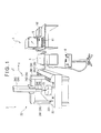
- Fig. 1 is a schematic illustration of an entire coordinate measuring machine according to the first exemplary embodiment of the invention.
- upper direction in Fig. 1 will be referred to as +Z-axis direction and two axes orthogonal to the Z-axis will be described as X-axis and Y-axis respectively, which also applies in the rest of the drawings.
- the coordinate measuring machine 1 (profile measuring instrument) includes: a coordinate measuring machine body 2; a motion controller 3 for performing a drive control over the coordinate measuring machine body 2; an operating unit 4 that provides a command to the motion controller 3 via an operation lever or the like to manually operate the coordinate measuring machine body 2; a host computer 5 that provides a predetermined command to the motion controller 3 and performs an arithmetic processing such as profile analysis of an object W placed on the coordinate measuring machine body 2; and an input unit 61 and an output unit 62 connected to the host computer 5.
- the input unit 61 is used for inputting measurement conditions and the like of the coordinate measuring machine 1 into the host computer 5.
- the output unit 62 is used for outputting measurement results of the coordinate measuring machine 1.
- the coordinate measuring machine body 2 includes: a probe 21 that has a measurement unit 211A at an end thereof (on -Z-axis direction side), the measurement unit 211 A being in contact with a surface of the object W; a movement mechanism 22 that holds a base end (on +Z-axis direction side) of the probe 21 and moves the probe 21; and a measurement stage 23 on which the movement mechanism 22 is vertically provided.
- a reference sphere 231 of a known diameter for calibrating the coordinate measuring machine body 2 is placed on the measurement stage 23.
- the reference sphere 231 can be placed at a plurality of locations on the measurement stage 23.
- the movement mechanism 22 includes: a slide mechanism 24 that holds the base end of the probe 21 while allowing a slide movement of the probe 21; and a drive mechanism 25 that drives the slide mechanism 24 to move the probe 21.
- the slide mechanism 24 includes: two columns 241 that extend from both X-axis-direction sides of the measurement stage 23 in +Z-axis direction, the columns 241 being slidable along Y-axis direction; a beam 242 that extends in X-axis direction being supported by the columns 241; a cylindrical slider 243 that alone Z-axis direction and is slidable on the beam 242 along X-axis direction; and a column 244 inserted in the slider 243, the column 244 being slidable in the slider 243 along Z-axis direction.
- the column 244 holds the base end of the probe 21 at -Z-axis direction end thereof.
- a plurality of types of probes are prepared for the probe 21, one of which is selected to be held by the column 244.
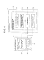
- Fig. 2 is a block diagram showing a schematic arrangement of the coordinate measuring machine 1.
- the drive mechanism 25 includes: a Y-axis driving section 251Y that supports and slidably moves one of the columns 241 located at +X-axis direction side along Y-axis direction; an X-axis driving section 251X that slides the slider 243 on the beam 242 along X-axis direction (not shown in Fig. 1 ); and a Z-axis driving section 251Z (not shown in Fig. 1 ) that slides the column 244 in the slider 243 to move the column 244 along Z-axis direction.
- the X-axis driving section 251X, the Y-axis driving section 251 Y and the Z-axis driving section 251Z are respectively provided with an X-axis scale sensor 252X, a Y-axis scale sensor 252Y and a Z-axis scale sensor 252Z for detecting the positions of the slider 243, the columns 241 and the column 244 in the respective axis directions.
- the scale sensors 252X, 252Y and 252Z are position sensors that output pulse signals corresponding to the positions of the slider 243, the columns 241 and the column 244.
- Fig. 3 is an enlarged schematic illustration showing a part of the column 244 at which the probe 21 is held.
- the probe 21 includes: a stylus 211 that has a measurement unit 211 A at an end thereof; a support mechanism 212 that supports a base end of the stylus 211; and a rotation mechanism 213 that allows the rotation of the support mechanism 212 relative to the column 244.
- the support mechanism 212 biases the stylus 211 in respective axis-directions (X, Y and Z-axis directions) so that the stylus 211 is located at a predetermined position while allowing the movement of the stylus 211 within a predetermined range in X, Y and Z-axis directions when an external force is applied (i.e. when the stylus 211 is in contact with the object W).
- the support mechanism 212 includes an X-axis probe sensor 212X, a Y-axis probe sensor 212Y and a Z-axis probe sensor 212Z for detecting the position of the stylus 211 in the respective axis-directions.
- the probe sensors 212X, 212Y and 212Z are position sensors that output pulse signals corresponding to the position of the stylus 211 in the respective axis directions.
- the rotation mechanism 213 is a mechanism that rotates the support mechanism 212 and the stylus 211 to change the orientation (i.e. attitude: a direction from the base end of the probe 21 toward a tip thereof) of the probe 21.
- the rotation mechanism 213 allows the rotation of the support mechanism 212 and the stylus 211 on the respective X, Y and Z-axes around a reference point R.
- the motion controller 3 includes: a drive control unit 31 that controls the drive mechanism 25 in response to a command from the operating unit 4 or the host computer 5; and a counter unit 32 that counts the pulse signals outputted from the scale sensors 252X, 252Y and 252Z and the probe sensors 212X, 212Y and 212Z.
- the counter unit 32 includes: a scale counter 321 that counts the pulse signals outputted by the scale sensors 252X, 252Y and 252Z to measure the position of the slide mechanism 24 (xs, ys, zs); and a probe counter 322 that counts the pulse signals outputted by the probe sensors 212X, 212Y and 212Z, in which a coordinate system based on the attitude of the probe 21 is converted into a coordinate system of the scale sensor to obtain the position of the stylus 211 (xp, yp, zp) after being converted to the coordinate system of the scale sensor.
- the position of the slide mechanism 24 measured by the scale counter 321 (referred to as a scale value S) and the position of the stylus 211 measured by the probe counter 322 after being converted (referred to as a probe value P) are outputted to the host computer 5.
- the host computer 5 (a controller) includes a CPU (Central Processing Unit), a memory and the like and provides a predetermined command to the motion controller 3 to control the coordinate measuring machine body 2, in which: a movement command unit 51; a position acquiring unit 52; a measurement value calculating unit 53; a form analyzing unit 54; and a storage 55 are provided.
- a CPU Central Processing Unit
- the movement command unit 51 provides a predetermined command to the drive control unit 31 of the motion controller 3 to cause the scanning movement of the slide mechanism 24 of the coordinate measuring machine body 2. Specifically, the movement command unit 51 outputs a scanning vector as a command value indicating a movement direction and a movement speed of the scanning movement of the probe 21 while the measurement unit 211A is in contact with a surface of the object W. Incidentally, in this exemplary embodiment, the movement command unit 51 sequentially outputs a scanning vector for conducting an autonomous scanning measurement in which the measurement unit 211A is autonomously moved along a surface of a cylindrical object W while controlling the position of the probe 21 so that the load applied on the measurement unit 211 A becomes constant.
- the position acquiring unit 52 acquires the scale value S and the probe value P measured by the scale counter 321 and the probe counter 322 at a predetermined sampling interval.
- the measurement value calculating unit 53 calculates the position of the measurement unit 211A based on the scale value S and the probe value P acquired by the position acquiring unit 52.
- the scale value S is adjusted so that the scale value S represents the position of the measurement unit 211A under condition that: the probe 21 is oriented in -Z-axis direction; and the deformation of the slide mechanism 24 on account of the scanning movement and the displacement of the stylus 211 in the support mechanism 212 are not caused.
- the form analyzing unit 54 synthesizes the measurement value calculated by the measurement value calculating unit 53 to calculate a surface profile data of the object W and conducts a profile analysis such as comparison of the calculated surface profile data of the object W with a profile data of the object W previously stored in the storage 55 to obtain an error, distortion and the like.
- the storage 55 stores the data used in the host computer 5 such as the measurement conditions inputted via the input unit 61 and the measurement result outputted via the output unit 62.
- the measurement conditions inputted via the input unit 61 include the profile data of the object W used in the form analyzing unit 54, a sampling interval for acquiring the scale value S and the probe value P by the position acquiring unit 52 and the like.
- Fig. 4 is a block diagram showing a detailed arrangement of the measurement value calculating unit 53.
- the measurement value calculating unit 53 includes: a rotation frequency calculating unit 531; a compensation-amount calculating unit 532; a compensator 533; and a synthesizing unit 534.
- the rotation frequency calculating unit 531 calculates the rotation frequency of the scanning movement of the probe 21 based on the command value outputted by the movement command unit 51.
- Fig. 5 is an illustration showing a calculation of the rotation frequency of the scanning movement of the probe 21 by the rotation frequency calculating unit 531.
- the rotation frequency calculating unit 531 approximates the path of the probe 21 drawn according to a command value Pt (xt, yt, zt) outputted by the movement command unit 51 with an arc to calculate a center P0 (X0, Y0, Z0) and a radius r of the arc and differentiates the command value Pt outputted by the movement command unit 51 to calculate the velocity v of the probe 21 as shown in the following formula (3), in which a velocity obtained by differentiating the command value xt is represented by xv, a velocity obtained by differentiating the command value yt is represented by yv and a velocity obtained by differentiating the command value zt is represented by zv.
- v x ⁇ v 2 + yv 2 + zv 2
- the rotation frequency calculating unit 531 calculates the rotation frequency f based on the radius r the velocity v as shown in the following formula (4).
- f v 2 ⁇ ⁇ ⁇ r
- the compensation-amount calculating unit 532 calculates a compensation amount for compensating the Abbe's error E (E X , E Y , E Z ) based on the rotation frequency f outputted by the rotation frequency calculating unit 531. Specifically, the compensation-amount calculating unit 532 calculates a compensation amount for compensating the error in the position of the measurement unit 211A caused by the scanning movement of the probe 21 based on the rotation frequency f calculated by the rotation frequency calculating unit 531.
- the Abbe's error E X in X-axis direction can be expressed as a resultant of: a translation error CT X of the probe 21 at the reference point R that is set adjacent to the base end of the probe 21; and a rotation error CR X of the probe 21 obtained based on a rotation angle ⁇ ye of the probe 21 around the reference point R and a length L of the probe 21 from the reference point R to the measurement unit 211A (referred to as a swivel length L hereinafter) as shown in the following formula (5).
- E X CT X + CR X
- the rotation angles of the respective X, Y and Z-axes are respectively represented by ⁇ xe, ⁇ ye and ⁇ ze, which are defined positive in rightward screwing direction of the respective axes and are respectively originated (i.e. at 0) at a position aligned with +Y-axis direction, +Z-axis direction and +X-axis direction.
- the Abbe's errors E Y and E Z in Y and Z-axis directions can be expressed by resultants of translation errors CT Y and CT Z and rotation errors CR Y and CR Z (see formula (5)).
- the compensation-amount calculating unit 532 calculates the translation error CT (CT X , CT Y , CT Z ) as a translation-compensation amount and calculates the rotation error CR (CR X , CR Y , CR Z ) as a rotation compensation amount.
- the compensation-amount calculating unit 532 calculates the translation-compensation amount CT based on predetermined coefficients (referred to as translation coefficient(s) hereinafter), the command value Pt outputted by the movement command unit 51 and the center P0 calculated by the rotation frequency calculating unit 531 as shown in the following formula (6).
- CTx CTy CTz xxe xye xze yxe yye yze zxe zye zze ⁇ xt - X ⁇ 0 yt - Y ⁇ 0 zt - Z ⁇ 0
- the translation coefficients in the above formula (6) are calculated according to the following formula (7) that is modeled as polynomial equations of the rotation frequency f calculated by the rotation frequency calculating unit 531.
- the compensation-amount calculating unit 532 calculates the translation-compensation amount CT based on the rotation frequency f.
- the compensation-amount calculating unit 532 calculates the rotation-compensation amount CR based on: lengths (L XY , L YZ , L XZ ) of orthographs of the swivel length L on X-Y plane, Y-Z plane and X-Z plane; the orientation ( ⁇ X0 , ⁇ Y0 , ⁇ Z0 ) of the probe 21 changed by the rotation mechanism 213; and a rotation angle ( ⁇ xe, ⁇ ye, ⁇ ze) of the probe 21 around the reference point R as shown in the following formula (9).
- CR X L XY ⁇ cos ⁇ Z ⁇ 0 + ⁇ Ze - cos ⁇ Z ⁇ 0 + L XZ ⁇ sin ⁇ Y ⁇ 0 + ⁇ Ye - sin ⁇ Y ⁇ 0
- CR Y L YZ ⁇ cos ⁇ X ⁇ 0 + ⁇ Xe - cos ⁇ X ⁇ 0 + L XY ⁇ sin ⁇ Z ⁇ 0 + ⁇ Ze - sin ⁇ Z ⁇ 0
- CR Z L XZ ⁇ cos ⁇ Y ⁇ 0 + ⁇ Ye - cos ⁇ Y ⁇ 0 + L YZ ⁇ sin ⁇ X ⁇ 0 + ⁇ Xe - sin ⁇ X ⁇ 0
- the compensation-amount calculating unit 532 calculates the lengths (L XY , L YZ , L XZ ) of orthographs of the swivel length L on X-Y plane, Y-Z plane and X-Z plane based on the length (L X , L Y , L X ) of the swivel length L in the respective axis-directions as shown in the following formula (10).
- L XY L X 2 + L Y 2
- L YZ L Y 2 + L Z 2
- L XZ L Z 2 + L X 2
- the compensation-amount calculating unit 532 calculates the orientation ( ⁇ X0 , ⁇ Y0 , ⁇ X0 ) of the probe 21 changed by the rotation mechanism 213 based on the size of the swivel length L as shown in the following formula (11), in which "sign" refers to a function that returns a sign numerical value.
- the compensation-amount calculating unit 532 calculates the rotation angle ( ⁇ xe, ⁇ ye, ⁇ ze) of the probe 21 around the reference point R based on predetermined coefficients (referred to as rotation coefficient(s) hereinafter), the command value Pt outputted by the movement command unit 51 and the center P0 calculated by the rotation frequency calculating unit 531 as shown in the following formula (12).
- ⁇ xe ⁇ ye ⁇ ze ⁇ xxe ⁇ xye ⁇ xze ⁇ yxe ⁇ yye ⁇ yze ⁇ zxe ⁇ zye ⁇ zze ⁇ xt - X ⁇ 0 yt - Y ⁇ 0 zt - Z ⁇ 0
- the rotation coefficients in the above formula (12) are calculated according to the following formula (13) that is modeled as polynomial equations of the rotation frequency f calculated by the rotation frequency calculating unit 531.
- the compensation-amount calculating unit 532 calculates the rotation-compensation amount CR based on the rotation frequency f.
- the change in the rotation error CR depends on the scale value S due to the structure of the slide mechanism 24, the coefficients of the polynomial equations of the rotation frequency fin the above formula (13) are modeled as polynomial equations of the scale value S as shown in the following formula (14), in which scale value S (xs, ys, zs) is represented as (x, y, z) for simplifying the formula.
- the coefficients in the polynomial equations in the above formulae (8) and (14) are separately determined in accordance with the attitude of the probe 21 according to the following conditional equations (15A) to (15F).
- the compensation-amount calculating unit 532 calculates the translation-compensation amount CT and the rotation-compensation amount CR based on the rotation frequency f and the coefficients determined in accordance with the attitude of the probe 21.
- the compensation-amount calculating unit 532 calculates the translation-compensation amount CT and the rotation-compensation amount CR based on the rotation frequency f and the coefficients determined in accordance with the rotation frequency f.
- the coefficients of the polynomial equations in the equations (15A) to (15F) are calculated by measuring the Abbe's error E in this exemplary embodiment.
- the Abbe's error E is measured by: obtaining the position of the measurement unit 211A during a scanning movement of the probe 21 at a constant angular velocity while the measurement unit 211A is in contact with the reference sphere 231; and subtracting the radius of the reference sphere 231 from the radius of the circle determined based on the position of the measurement unit 211A.
- the Abbe's error E is measured while changing respective conditions of: the orientation of the probe 21 ( ⁇ X-axis direction, ⁇ Y-axis direction and -Z-axis direction); the position of the slide mechanism 24 (xs, ys, zs); the swivel length L; and the scanning movement velocity v.
- the orientation of the probe 21 in +Z-axis direction is not listed as the above conditions because the probe 21 cannot be oriented in +Z-axis direction due to the structure of the coordinate measuring machine body 2 (see Fig. 1 ). Further, when the probe 21 is oriented in ⁇ X-axis direction, the probe 21 is subjected to a scanning movement within Y-Z plane to measure errors E Y , E Z . When the probe 21 is oriented in ⁇ Y-axis direction, the probe 21 is subjected to a scanning movement within X-Z plane to measure errors E X , E Z . When the probe 21 is oriented in -Z-axis direction, the probe 21 is subjected to a scanning movement within X-Y plane to measure errors E X , E Y .
- the compensator 533 compensates the scale value S acquired by the position acquiring unit 52 based on the translation-compensation amount CT and the rotation-compensation amount CR calculated by the compensation-amount calculating unit 532. Specifically, the compensator 533 compensates the error in the position of the measurement unit 211A caused by the scanning movement of the probe 21 based on the translation-compensation amount CT and the rotation-compensation amount CR calculated by the compensation-amount calculating unit 532.
- the compensator 533 calculates the compensated scale value C (xc, yc, zc) based on the scale value S and the Abbe's error E as shown in the following formula (16).
- xc xs - E
- X yc ys - E
- Y zc zs - E Z
- the synthesizing unit 534 calculates the measurement value by synthesizing the scale value C compensated by the compensator 533 and the probe value P acquired by the position acquiring unit 52.
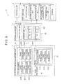
- Fig. 6 is a block diagram showing a relationship between respective components of the measurement value calculating unit 53.
- the measurement value calculating unit 53 calculates the measurement value based on the command value Pt, the swivel length L, the scale value S and the probe value P (see Fig 6 ).
- the rotation frequency calculating unit 531 calculates the center P0 and the rotation frequency f based on the command value Pt.
- the compensation-amount calculating unit 532 calculates the compensation amount (translation-compensation amount CT and rotation-compensation amount CR) based on the command value Pt, the center P0 the rotation frequency f, the swivel length L and the scale value S.
- the compensator 533 compensates the scale value S acquired by the position acquiring unit 52 based on the compensation amount calculated by the compensation-amount calculating unit 532.
- the synthesizing unit 534 calculates the measurement value by synthesizing the scale value C compensated by the compensator 533 and the probe value P acquired by the position acquiring unit 52.
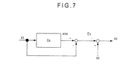
- Fig. 7 is an illustration showing a model of Abbe's error to be compensated by the coordinate measuring machine 1. Incidentally, Fig. 7 only shows a model of Abbe's error in X-axis direction.
- the position xes of the slide mechanism 24 can be estimated according to a command value xt outputted by the movement command unit 51 and a nominal model Gx representing a transfer function until the scale value S and the probe value P are acquired by the position acquiring unit 52 after the command value xt is outputted by the movement command unit 51, as shown in Fig. 7
- the difference between the command value xt outputted by the movement command unit 51 and the estimated position xes of the slide mechanism 24 is the estimated Abbe's error Ex. Accordingly, the compensated scale value xc can be calculated by synthesizing the Abbe's error E X and the scale value xs.
- the model of the Abbe's error E X to be compensated by the coordinate measuring machine 1 corresponds to the nominal model Gx.
- the above description for X-axis direction also applies to Y and Z-axis directions.
- Fig. 8 shows an example of the nominal model Gx.
- An example of the nominal model Gx is a model represented by a high-order transfer function of springs SP1, SP2 connecting the command value Pt and the estimated position ES (xes, yes, zes) of the slide mechanism 24 and masses M1, M2, as shown in Fig. 8 .
- the compensation-amount calculating unit 532 calculates the translation-compensation amount CT and the rotation-compensation amount CR based on the rotation frequency f, even when the model of the Abbe's error E X has to be expressed by a high-order transfer function as in the nominal model Gx shown in Fig. 8 , the Abbe's error E X can be appropriately compensated.
- Fig. 9 is a block diagram showing a schematic arrangement of a coordinate measuring machine 1A according to the second exemplary embodiment of the invention.
- the coordinate measuring machine 1 includes the host computer 5, and the host computer 5 includes the movement command unit 51 and the measurement value calculating unit 53.
- the coordinate measuring machine 1A according to the second exemplary embodiment includes a host computer 5A, and the host computer 5A includes a path setting unit 56, a movement command unit 51A and a measurement value calculating unit 53A.
- the path setting unit 56 designates the path of the probe 21 by setting a center P0 and a radius r of an arc and a velocity set value vt of the probe 21.
- the movement command unit 51A outputs a scanning vector (the command value Pt) for moving the probe 21 based on the center P0 and the radius r of the arc and the velocity set value vt of the probe 21 designated by the path setting unit 56.
- the movement command unit 51A sequentially outputs a scanning vector for conducting a design-value scanning measurement in which the measurement unit 211 A is moved along a surface of the object W by controlling the position of the probe 21 to accord to a profile data (designed value of the surface profile of the object W) of the object W.
- Fig. 10 is a block diagram showing a detailed arrangement of the measurement value calculating unit 53A.
- the measurement value calculating unit 53A includes a rotation frequency calculating unit 531A.
- the rotation frequency calculating unit 531A differentiates the command value Pt to calculate the velocity v of the probe 21 and calculates the rotation frequency f based on the velocity v of the probe 21 and the radius r designated by the path setting unit 56.
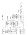
- Fig. 11 shows a relationship between the path setting unit 56, the movement command unit 51A and respective of the measurement value calculating unit 53A.
- the measurement value calculating unit 53A calculates the measurement value based on the center P0, the radius r, the command value Pt, the swivel length L, the scale value S and the probe value P (see Fig 11 ).
- This exemplary embodiment provides the following advantages in addition to the same advantages as the advantages (1) to (3) and (5) to (7) in the first exemplary embodiment.
- the rotation frequency may be acquired with the use of a sensor and the like. In other words, it is only for the controller to calculate at least one of the translation-compensation amount and the rotation-compensation amount based on the rotation frequency of the scanning movement of the probe.
- the compensation-amount calculating unit 532 calculates the translation-compensation amount CT and the rotation-compensation amount CR based on the rotation frequency f in the above exemplary embodiments, it is sufficient that at least one of the translation-compensation amount CT and the rotation-compensation amount CR is calculated.
- the compensation-amount calculating unit 532 calculates the translation-compensation amount CT and the rotation-compensation amount CR based on the rotation frequency f and the coefficients determined in accordance with the attitude of the probe 21 in the above exemplary embodiments, the coefficients may not be determined in accordance with the attitude of the probe.
- the movement command units 51, 51A, the position acquiring unit 52 and the measurement value calculating units 53, 53A are provided to the host computers 5, 5A in the above exemplary embodiments, a part or the entirety of the above components may be provided to the motion controller 3.
- the coordinate measuring machines 1, 1A include the contact-type probe 21 having the measurement unit 211A to be in contact with a surface of the object W.
- the profile measuring instrument may be provided with a non-contact type probe such as a laser device or a camera. In other words, since the profile measuring instrument compensates the Abbe's error caused by the scanning movement of the probe, it is only necessary for the profile measuring instrument to have a probe provided with a measurement unit.
- the coordinate measuring machines 1, 1A include the probe 21 provided with the rotation mechanism 213 that rotates the support mechanism 212 and the stylus 211 to change the attitude of the probe 21.
- the profile measuring instrument may be provided with a probe having no rotation mechanism.
- the reference point may be set at a base point of the probe.
Landscapes
- Physics & Mathematics (AREA)
- General Physics & Mathematics (AREA)
- A Measuring Device Byusing Mechanical Method (AREA)
Abstract
Description
- The present invention relates to a profile measuring instrument.
- A known profile measuring instrument includes: a probe having a measurement unit for measuring an object; a movement mechanism for moving the probe; and a controller for controlling the movement mechanism, the measurement unit being moved along a surface of the object to measure a profile of the object (see, for instance, Patent Literature 1:
JP-A-55-154408 JP-A-07-324928 - A coordinate measuring machine according to the Patent Literature 1 uses acceleration of respective driven components or acceleration obtained by a drive motor in order to compensate measurement errors caused by a deflection of a movement mechanism on account of inertial force during the scanning movement of the probe, i.e. dynamic deflection (dynamic Abbe's error) caused by a deformation of the movement mechanism.
- The CMM (Coordinate Measuring Machine) disclosed in the
Patent Literature 2 calculates a compensation value representing deflection characteristics of the movement mechanism as a function of the probe position and acceleration in order to compensate the aforementioned dynamic Abbe's error. -
Fig. 12 is an illustration showing a model of Abbe's error to be compensated by a conventional profile measuring instrument. - Specifically, the CMM disclosed in the
Patent Literature 2 models the Abbe's error as a spring SP connecting a probe position Ps (xs, ys, zs) and a compensated probe position Pc (xc, yc, zc) as shown inFig. 12 . A spring constant K of the spring SP represents the deflection characteristics of the movement mechanism, which are dependent on the probe position Ps. - Accordingly, for instance, a relationship between the probe position xs and the compensated position xc in X-axis can be expressed by the following formula (1) based on the spring constant K and a force F applied on the spring SP.

- Further, the force F is caused on account of the inertial force during the scanning movement of the probe, the force F is proportional to acceleration a of the probe. In other words, the relationship between the probe position xs and the compensated probe position xc can be expressed by the following formula (2), where Ka represents a proportion constant between the force F and the acceleration a of the probe.

- As described above, the CMM disclosed in the
Patent Literature 2 can compensate the Abbe's error based on a function of the probe position Ps and the acceleration a. - However, since the CMM disclosed in the
Patent Literature 2 compensates the Abbe's error based on the function of the probe position Ps and the acceleration a, the Abbe's error cannot be appropriately compensated when the model of the Abbe's error has to be expressed by a high-order transfer function. - Specifically, since the CMM disclosed in the
Patent Literature 2 compensates the Abbe's error based on the function of the acceleration a, if one tries to transform the model of the Abbe's error into a function of, for instance, frequency (e.g. a function of rotation frequency of the scanning movement of the probe according to the present invention, which will be described below), only a second-order term of the function can be expressed. Further, the model of thePatent Literature 2 cannot be directly transformed into a transfer function. In thePatent Literature 2, instead of a given mass M, the force F is obtained by acceleration (movement condition) of the mass M to be used for compensation. - An object of the invention is to provide a profile measuring instrument that can appropriately compensate the Abbe's error.
- A profile measuring instrument according to an aspect of the invention includes: a probe having a measurement unit for measuring an object; a movement mechanism that moves the probe; and a controller for controlling the movement mechanism, the measurement unit being moved along a surface of the object to measure a profile of the object, the controller including: a compensation-amount calculating unit that calculates a compensation amount for compensating an error in a position of the measurement unit caused by a scanning movement of the probe; and a compensator that compensates the error in the position of the measurement unit based on the compensation amount calculated by the compensation-amount calculating unit, the compensation-amount calculating unit calculating: a translation-compensation amount for compensating a translation error of the probe at a reference point that is set to the probe; and a rotation-compensation amount for compensating a rotation error of the probe based on a rotation angle of the probe around the reference point and a length of the probe from the reference point to the measurement unit, in which at least one of the translation-compensation amount and the rotation-compensation amount is calculated based on a rotation frequency of the scanning movement of the probe.
- According to the above arrangement, since the compensation-amount calculating unit calculates at least one of the translation-compensation amount and the rotation-compensation amount based on the rotation frequency of the scanning movement of the probe, even when the model of the Abbe's error has to be represented by a high-order transfer function, the Abbe's error can be appropriately compensated.
- This is because, since the transfer function is a function of a frequency, a model of Abbe's error of a high-order transfer function can be expressed by approximating the Abbe's error of a high-order transfer function with a polynomial equation of the rotation frequency.
- Further, in such a profile measuring instrument, a multiple of probes are generally exchangeable in order to measure a profile of various objects. Recently, some of the probes are adapted to be rotated relative to the movement mechanism to change the attitude thereof.
- Further, when the length and attitude of the probe are different, though the translation-compensation amount stays substantially constant, the rotation-compensation amount varies in accordance with the length and attitude of the probe.
- According to the above of the invention, since the profile measuring instrument includes the compensation-amount calculating unit for separately calculating the translation-compensation amount and the rotation-compensation amount, even when probes of different lengths are used or the attitude of the probe is changed, appropriate compensation amount can be calculated.
- Incidentally, when a probe of which attitude is used, the reference point is preferably set at a rotation center of the probe when the probe is rotated relative to the movement mechanism. By setting the reference point as in the above, the rotation-compensation amount can be calculated based on a composition of a rotation angle of the probe relative to the movement mechanism when the probe changes the attitude thereof and a rotation angle of the probe caused due to the deformation of the movement mechanism.
- In the above aspect of the invention, the controller preferably includes a rotation frequency calculating unit that approximates a path of the probe based on the command value by an arc to calculate a center and a radius of the arc and differentiates the command value to calculate a velocity of the probe to calculate the rotation frequency.
- The following two methods have been proposed for measuring a profile of an object by moving the measurement unit along the surface of the object: (1) an autonomous scanning measurement in which a measurement unit is autonomously moved along the surface of the object while controlling the position of the probe so that the load applied on the measurement unit becomes constant; and (2) design-value scanning measurement in which the measurement unit is moved along the surface of the object by controlling the position of the probe to accord to a design value of the surface profile of the object.
- According to the above arrangement, since the rotation frequency calculating unit calculates the rotation frequency based on the command value, the Abbe's error of the autonomous scanning movement can be appropriately compensated.
- In the above aspect of the invention, the controller preferably includes: a path setting unit that designates a path of the probe by a center and a radius of an arc and a velocity set value of the probe; a movement command unit that outputs a command value for moving the probe based on the center and the radius of the are and the velocity set value of the probe that are designated by the path setting unit; and a rotation frequency unit differentiates the command value to calculate the velocity of the probe and calculates the rotation frequency based on the velocity of the probe and the radius designated by the path setting unit.
- According to the above arrangement, since the rotation frequency calculating unit calculates the rotation frequency based on the radius determined by the path setting unit, the Abbe's error of the design-value scanning movement can be appropriately compensated.
- In the above aspect of the invention, the compensation-amount calculating unit preferably calculates the translation-compensation amount and the rotation-compensation amount based on the rotation frequency and coefficients determined in accordance with an attitude of the probe.
- According to the above arrangement, since the coefficients for calculating the translation-compensation amount and the rotation-compensation amount are determined in accordance with the attitude of the probe, even when the translation-compensation amount and the rotation-compensation amount become discontinuous according to the attitude of the probe, the Abbe's error can be appropriately compensated.
- Incidentally, when the translation-compensation amount and the rotation-compensation amount become discontinuous due to the rotation frequency, with the use of segmented polynomial equations segmented at a discontinuous point or a spline function, the Abbe's error can be appropriately compensated as will be described later.
- In the above aspect of the invention, the compensation-amount calculating unit preferably calculates the translation-compensation amount and the rotation-compensation amount based on the rotation frequency, a position of the probe and coefficients determined in accordance with the rotation frequency and the position of the probe.
- According to the above arrangement, since the coefficients for calculating the translation-compensation amount and the rotation-compensation amount are determined in accordance with the rotation frequency and the position of the probe, the Abbe's error can be further appropriately compensated as compared to an arrangement in which constant coefficient(s) is used for calculating the translation-compensation amount and the rotation-compensation amount.
- In the above aspect of the invention, the compensation-amount calculating unit preferably calculates the translation-compensation amount and the rotation-compensation amount using a spline function or a segmented polynomial equation that is segmented in accordance with the rotation frequency.
- According to the above arrangement, even when the translation-compensation amount and the rotation-compensation amount become discontinuous, with the use of segmented polynomial equations segmented at the discontinuous point or a spline function, the coefficients with less error can be determined in accordance with the rotation frequency, so that the Abbe's error can be appropriately compensated.
- In the above aspect of the invention, the compensation-amount calculating unit preferably calculates the translation-compensation amount and the rotation-compensation amount based on the rotation frequency.
- According to the above arrangement, since the compensation-amount calculating unit calculates the translation-compensation amount and the rotation-compensation amount based on the rotation frequency, the Abbe's error can be further appropriately compensated as compared to an arrangement in which at least one of the translation-compensation amount and the rotation-compensation amount is calculated.
-
-
Fig. 1 is a schematic illustration of an entire coordinate measuring machine according to a first exemplary embodiment of the invention. -
Fig. 2 is a block diagram showing a schematic arrangement of the coordinate measuring machine according to the first exemplary embodiment of the invention. -
Fig. 3 is an enlarged schematic illustration showing a part of a column at which a probe is held according to the first exemplary embodiment of the invention. -
Fig. 4 is a block diagram showing a detailed arrangement of a measurement value calculating unit according to the first exemplary embodiment of the invention. -
Fig. 5 is an illustration showing a calculation of a rotation frequency of a scanning movement of the probe by a rotation frequency calculating unit according to the first exemplary embodiment of the invention. -
Fig. 6 is an illustration showing a relationship between respective components of the measurement value calculating unit according to the first exemplary embodiment of the invention. -
Fig. 7 is an illustration showing a model of Abbe's error to be compensated by the coordinate measuring machine according to the first exemplary embodiment of the invention. -
Fig. 8 is an illustration showing an example of a nominal model according to the first exemplary embodiment of the invention. -
Fig. 9 is a block diagram showing a schematic arrangement of the coordinate measuring machine according to a second exemplary embodiment of the invention. -
Fig. 10 is a block diagram showing a detailed arrangement of a measurement value calculating unit according to the second exemplary embodiment of the invention. -
Fig. 11 is an illustration showing a relationship between a path setting unit, movement command unit and respective components of the measurement value calculating unit according to the second exemplary embodiment of the invention. -
Fig. 12 is an illustration showing a model of Abbe's error to be compensated by a conventional profile measuring instrument. - A first exemplary embodiment of the invention will be described below with reference to the attached drawings.
-
Fig. 1 is a schematic illustration of an entire coordinate measuring machine according to the first exemplary embodiment of the invention. Incidentally, upper direction inFig. 1 will be referred to as +Z-axis direction and two axes orthogonal to the Z-axis will be described as X-axis and Y-axis respectively, which also applies in the rest of the drawings. - As shown in
Fig. 1 , the coordinate measuring machine 1 (profile measuring instrument) includes: a coordinatemeasuring machine body 2; amotion controller 3 for performing a drive control over the coordinatemeasuring machine body 2; anoperating unit 4 that provides a command to themotion controller 3 via an operation lever or the like to manually operate the coordinatemeasuring machine body 2; ahost computer 5 that provides a predetermined command to themotion controller 3 and performs an arithmetic processing such as profile analysis of an object W placed on the coordinatemeasuring machine body 2; and aninput unit 61 and anoutput unit 62 connected to thehost computer 5. Incidentally, theinput unit 61 is used for inputting measurement conditions and the like of the coordinate measuring machine 1 into thehost computer 5. Theoutput unit 62 is used for outputting measurement results of the coordinate measuring machine 1. - The coordinate measuring
machine body 2 includes: aprobe 21 that has ameasurement unit 211A at an end thereof (on -Z-axis direction side), themeasurement unit 211 A being in contact with a surface of the object W; amovement mechanism 22 that holds a base end (on +Z-axis direction side) of theprobe 21 and moves theprobe 21; and ameasurement stage 23 on which themovement mechanism 22 is vertically provided. Incidentally, areference sphere 231 of a known diameter for calibrating the coordinate measuringmachine body 2 is placed on themeasurement stage 23. Thereference sphere 231 can be placed at a plurality of locations on themeasurement stage 23. - The
movement mechanism 22 includes: aslide mechanism 24 that holds the base end of theprobe 21 while allowing a slide movement of theprobe 21; and adrive mechanism 25 that drives theslide mechanism 24 to move theprobe 21. - The
slide mechanism 24 includes: twocolumns 241 that extend from both X-axis-direction sides of themeasurement stage 23 in +Z-axis direction, thecolumns 241 being slidable along Y-axis direction; abeam 242 that extends in X-axis direction being supported by thecolumns 241; acylindrical slider 243 that alone Z-axis direction and is slidable on thebeam 242 along X-axis direction; and acolumn 244 inserted in theslider 243, thecolumn 244 being slidable in theslider 243 along Z-axis direction. Thecolumn 244 holds the base end of theprobe 21 at -Z-axis direction end thereof. A plurality of types of probes are prepared for theprobe 21, one of which is selected to be held by thecolumn 244. -
Fig. 2 is a block diagram showing a schematic arrangement of the coordinate measuring machine 1. - As shown in
Figs. 1 and2 , thedrive mechanism 25 includes: a Y-axis driving section 251Y that supports and slidably moves one of thecolumns 241 located at +X-axis direction side along Y-axis direction; anX-axis driving section 251X that slides theslider 243 on thebeam 242 along X-axis direction (not shown inFig. 1 ); and a Z-axis driving section 251Z (not shown inFig. 1 ) that slides thecolumn 244 in theslider 243 to move thecolumn 244 along Z-axis direction. - As shown in
Fig. 2 , theX-axis driving section 251X, the Y-axis driving section 251 Y and the Z-axis driving section 251Z are respectively provided with anX-axis scale sensor 252X, a Y-axis scale sensor 252Y and a Z-axis scale sensor 252Z for detecting the positions of theslider 243, thecolumns 241 and thecolumn 244 in the respective axis directions. Incidentally, thescale sensors slider 243, thecolumns 241 and thecolumn 244. -
Fig. 3 is an enlarged schematic illustration showing a part of thecolumn 244 at which theprobe 21 is held. - As shown in
Fig. 3 , theprobe 21 includes: astylus 211 that has ameasurement unit 211 A at an end thereof; asupport mechanism 212 that supports a base end of thestylus 211; and arotation mechanism 213 that allows the rotation of thesupport mechanism 212 relative to thecolumn 244. - The
support mechanism 212 biases thestylus 211 in respective axis-directions (X, Y and Z-axis directions) so that thestylus 211 is located at a predetermined position while allowing the movement of thestylus 211 within a predetermined range in X, Y and Z-axis directions when an external force is applied (i.e. when thestylus 211 is in contact with the object W). As shown inFig. 2 , thesupport mechanism 212 includes anX-axis probe sensor 212X, a Y-axis probe sensor 212Y and a Z-axis probe sensor 212Z for detecting the position of thestylus 211 in the respective axis-directions. Incidentally, similarly to thescale sensors probe sensors stylus 211 in the respective axis directions. - The
rotation mechanism 213 is a mechanism that rotates thesupport mechanism 212 and thestylus 211 to change the orientation (i.e. attitude: a direction from the base end of theprobe 21 toward a tip thereof) of theprobe 21. Incidentally, therotation mechanism 213 allows the rotation of thesupport mechanism 212 and thestylus 211 on the respective X, Y and Z-axes around a reference point R. - As shown in
Fig. 2 , themotion controller 3 includes: adrive control unit 31 that controls thedrive mechanism 25 in response to a command from theoperating unit 4 or thehost computer 5; and acounter unit 32 that counts the pulse signals outputted from thescale sensors probe sensors - The
counter unit 32 includes: ascale counter 321 that counts the pulse signals outputted by thescale sensors probe counter 322 that counts the pulse signals outputted by theprobe sensors probe 21 is converted into a coordinate system of the scale sensor to obtain the position of the stylus 211 (xp, yp, zp) after being converted to the coordinate system of the scale sensor. The position of theslide mechanism 24 measured by the scale counter 321 (referred to as a scale value S) and the position of thestylus 211 measured by theprobe counter 322 after being converted (referred to as a probe value P) are outputted to thehost computer 5. - The host computer 5 (a controller) includes a CPU (Central Processing Unit), a memory and the like and provides a predetermined command to the
motion controller 3 to control the coordinate measuringmachine body 2, in which: amovement command unit 51; aposition acquiring unit 52; a measurementvalue calculating unit 53; aform analyzing unit 54; and astorage 55 are provided. - The
movement command unit 51 provides a predetermined command to thedrive control unit 31 of themotion controller 3 to cause the scanning movement of theslide mechanism 24 of the coordinate measuringmachine body 2. Specifically, themovement command unit 51 outputs a scanning vector as a command value indicating a movement direction and a movement speed of the scanning movement of theprobe 21 while themeasurement unit 211A is in contact with a surface of the object W. Incidentally, in this exemplary embodiment, themovement command unit 51 sequentially outputs a scanning vector for conducting an autonomous scanning measurement in which themeasurement unit 211A is autonomously moved along a surface of a cylindrical object W while controlling the position of theprobe 21 so that the load applied on themeasurement unit 211 A becomes constant. - The
position acquiring unit 52 acquires the scale value S and the probe value P measured by thescale counter 321 and the probe counter 322 at a predetermined sampling interval. - The measurement
value calculating unit 53 calculates the position of themeasurement unit 211A based on the scale value S and the probe value P acquired by theposition acquiring unit 52. Incidentally, the scale value S is adjusted so that the scale value S represents the position of themeasurement unit 211A under condition that: theprobe 21 is oriented in -Z-axis direction; and the deformation of theslide mechanism 24 on account of the scanning movement and the displacement of thestylus 211 in thesupport mechanism 212 are not caused. - The
form analyzing unit 54 synthesizes the measurement value calculated by the measurementvalue calculating unit 53 to calculate a surface profile data of the object W and conducts a profile analysis such as comparison of the calculated surface profile data of the object W with a profile data of the object W previously stored in thestorage 55 to obtain an error, distortion and the like. - The
storage 55 stores the data used in thehost computer 5 such as the measurement conditions inputted via theinput unit 61 and the measurement result outputted via theoutput unit 62. Incidentally, the measurement conditions inputted via theinput unit 61 include the profile data of the object W used in theform analyzing unit 54, a sampling interval for acquiring the scale value S and the probe value P by theposition acquiring unit 52 and the like. -
Fig. 4 is a block diagram showing a detailed arrangement of the measurementvalue calculating unit 53. - As shown in
Fig. 4 , the measurementvalue calculating unit 53 includes: a rotationfrequency calculating unit 531; a compensation-amount calculating unit 532; acompensator 533; and asynthesizing unit 534. - The rotation
frequency calculating unit 531 calculates the rotation frequency of the scanning movement of theprobe 21 based on the command value outputted by themovement command unit 51. -
Fig. 5 is an illustration showing a calculation of the rotation frequency of the scanning movement of theprobe 21 by the rotationfrequency calculating unit 531. - Specifically, as shown in
Fig. 5 , the rotationfrequency calculating unit 531 approximates the path of theprobe 21 drawn according to a command value Pt (xt, yt, zt) outputted by themovement command unit 51 with an arc to calculate a center P0 (X0, Y0, Z0) and a radius r of the arc and differentiates the command value Pt outputted by themovement command unit 51 to calculate the velocity v of theprobe 21 as shown in the following formula (3), in which a velocity obtained by differentiating the command value xt is represented by xv, a velocity obtained by differentiating the command value yt is represented by yv and a velocity obtained by differentiating the command value zt is represented by zv.
- Then, the rotation
frequency calculating unit 531 calculates the rotation frequency f based on the radius r the velocity v as shown in the following formula (4).
- The compensation-
amount calculating unit 532 calculates a compensation amount for compensating the Abbe's error E (EX, EY, EZ) based on the rotation frequency f outputted by the rotationfrequency calculating unit 531. Specifically, the compensation-amount calculating unit 532 calculates a compensation amount for compensating the error in the position of themeasurement unit 211A caused by the scanning movement of theprobe 21 based on the rotation frequency f calculated by the rotationfrequency calculating unit 531. - For instance, as shown in
Fig. 3 , when theprobe 21 is subjected to a scanning movement in X-axis direction (in a direction of an arrow A inFig. 3 ), the Abbe's error EX in X-axis direction can be expressed as a resultant of: a translation error CTX of theprobe 21 at the reference point R that is set adjacent to the base end of theprobe 21; and a rotation error CRX of theprobe 21 obtained based on a rotation angle θye of theprobe 21 around the reference point R and a length L of theprobe 21 from the reference point R to themeasurement unit 211A (referred to as a swivel length L hereinafter) as shown in the following formula (5).
- Incidentally, the rotation angles of the respective X, Y and Z-axes are respectively represented by θxe, θye and θze, which are defined positive in rightward screwing direction of the respective axes and are respectively originated (i.e. at 0) at a position aligned with +Y-axis direction, +Z-axis direction and +X-axis direction.
- Further, in the same manner as X-axis direction, the Abbe's errors EY and EZ in Y and Z-axis directions can be expressed by resultants of translation errors CTY and CTZ and rotation errors CRY and CRZ (see formula (5)).
- Accordingly, the compensation-
amount calculating unit 532 calculates the translation error CT (CTX, CTY, CTZ) as a translation-compensation amount and calculates the rotation error CR (CRX, CRY, CRZ) as a rotation compensation amount. - Specifically, the compensation-
amount calculating unit 532 calculates the translation-compensation amount CT based on predetermined coefficients (referred to as translation coefficient(s) hereinafter), the command value Pt outputted by themovement command unit 51 and the center P0 calculated by the rotationfrequency calculating unit 531 as shown in the following formula (6).
- The translation coefficients in the above formula (6) are calculated according to the following formula (7) that is modeled as polynomial equations of the rotation frequency f calculated by the rotation
frequency calculating unit 531. In other words, the compensation-amount calculating unit 532 calculates the translation-compensation amount CT based on the rotation frequency f.
- Further, since the change in the translation error CT depends on the scale value S due to the structure of the
slide mechanism 24, the coefficients of the polynomial equations of the rotation frequency f in the above formula (7) are modeled as polynomial equations of the scale value S as shown in the following formula (8), in which scale value S (xs, ys, zs) is represented as (x, y, z) for the formula.
- Next, the compensation-
amount calculating unit 532 calculates the rotation-compensation amount CR based on: lengths (LXY, LYZ, LXZ) of orthographs of the swivel length L on X-Y plane, Y-Z plane and X-Z plane; the orientation (θX0, θY0, θZ0) of theprobe 21 changed by therotation mechanism 213; and a rotation angle (θxe, θye, θze) of theprobe 21 around the reference point R as shown in the following formula (9).
- The compensation-
amount calculating unit 532 calculates the lengths (LXY, LYZ, LXZ) of orthographs of the swivel length L on X-Y plane, Y-Z plane and X-Z plane based on the length (LX, LY, LX) of the swivel length L in the respective axis-directions as shown in the following formula (10).
- The compensation-
amount calculating unit 532 calculates the orientation (θX0, θY0, θX0) of theprobe 21 changed by therotation mechanism 213 based on the size of the swivel length L as shown in the following formula (11), in which "sign" refers to a function that returns a sign numerical value.
- Further, the compensation-
amount calculating unit 532 calculates the rotation angle (θxe, θye, θze) of theprobe 21 around the reference point R based on predetermined coefficients (referred to as rotation coefficient(s) hereinafter), the command value Pt outputted by themovement command unit 51 and the center P0 calculated by the rotationfrequency calculating unit 531 as shown in the following formula (12).
- The rotation coefficients in the above formula (12) are calculated according to the following formula (13) that is modeled as polynomial equations of the rotation frequency f calculated by the rotation
frequency calculating unit 531. In other words, the compensation-amount calculating unit 532 calculates the rotation-compensation amount CR based on the rotation frequency f.
- Further, the change in the rotation error CR depends on the scale value S due to the structure of the
slide mechanism 24, the coefficients of the polynomial equations of the rotation frequency fin the above formula (13) are modeled as polynomial equations of the scale value S as shown in the following formula (14), in which scale value S (xs, ys, zs) is represented as (x, y, z) for simplifying the formula.
- The coefficients in the polynomial equations in the above formulae (8) and (14) are separately determined in accordance with the attitude of the
probe 21 according to the following conditional equations (15A) to (15F). In other words, the compensation-amount calculating unit 532 calculates the translation-compensation amount CT and the rotation-compensation amount CR based on the rotation frequency f and the coefficients determined in accordance with the attitude of theprobe 21.


- Further, when the coefficients of the polynomial equations in the above equations (15A) to (15F) become discontinuous according to the rotation frequency, segmented polynomial equations that are segmented at the discontinuous point or a spline function may be used to determine the coefficients of the polynomial equations with less errors according to the rotation frequency f. In other words, the compensation-
amount calculating unit 532 calculates the translation-compensation amount CT and the rotation-compensation amount CR based on the rotation frequency f and the coefficients determined in accordance with the rotation frequency f. - Incidentally, the coefficients of the polynomial equations in the equations (15A) to (15F) are calculated by measuring the Abbe's error E in this exemplary embodiment. Specifically, the Abbe's error E is measured by: obtaining the position of the
measurement unit 211A during a scanning movement of theprobe 21 at a constant angular velocity while themeasurement unit 211A is in contact with thereference sphere 231; and subtracting the radius of thereference sphere 231 from the radius of the circle determined based on the position of themeasurement unit 211A. - The Abbe's error E is measured while changing respective conditions of: the orientation of the probe 21 (±X-axis direction, ±Y-axis direction and -Z-axis direction); the position of the slide mechanism 24 (xs, ys, zs); the swivel length L; and the scanning movement velocity v.
- The orientation of the
probe 21 in +Z-axis direction is not listed as the above conditions because theprobe 21 cannot be oriented in +Z-axis direction due to the structure of the coordinate measuring machine body 2 (seeFig. 1 ). Further, when theprobe 21 is oriented in ±X-axis direction, theprobe 21 is subjected to a scanning movement within Y-Z plane to measure errors EY, EZ. When theprobe 21 is oriented in ±Y-axis direction, theprobe 21 is subjected to a scanning movement within X-Z plane to measure errors EX, EZ. When theprobe 21 is oriented in -Z-axis direction, theprobe 21 is subjected to a scanning movement within X-Y plane to measure errors EX, EY. - The
compensator 533 compensates the scale value S acquired by theposition acquiring unit 52 based on the translation-compensation amount CT and the rotation-compensation amount CR calculated by the compensation-amount calculating unit 532. Specifically, thecompensator 533 compensates the error in the position of themeasurement unit 211A caused by the scanning movement of theprobe 21 based on the translation-compensation amount CT and the rotation-compensation amount CR calculated by the compensation-amount calculating unit 532. - Specifically, since the Abbe's error E can be calculated by the above formula (5) according to the translation-compensation amount CT and the rotation-compensation amount CR, the
compensator 533 calculates the compensated scale value C (xc, yc, zc) based on the scale value S and the Abbe's error E as shown in the following formula (16).
- The synthesizing
unit 534 calculates the measurement value by synthesizing the scale value C compensated by thecompensator 533 and the probe value P acquired by theposition acquiring unit 52. -
Fig. 6 is a block diagram showing a relationship between respective components of the measurementvalue calculating unit 53. - As described above, the measurement
value calculating unit 53 calculates the measurement value based on the command value Pt, the swivel length L, the scale value S and the probe value P (seeFig 6 ). - Specifically, the rotation
frequency calculating unit 531 calculates the center P0 and the rotation frequency f based on the command value Pt. - The compensation-
amount calculating unit 532 calculates the compensation amount (translation-compensation amount CT and rotation-compensation amount CR) based on the command value Pt, the center P0 the rotation frequency f, the swivel length L and the scale value S. - The
compensator 533 compensates the scale value S acquired by theposition acquiring unit 52 based on the compensation amount calculated by the compensation-amount calculating unit 532. - The synthesizing
unit 534 calculates the measurement value by synthesizing the scale value C compensated by thecompensator 533 and the probe value P acquired by theposition acquiring unit 52. -
Fig. 7 is an illustration showing a model of Abbe's error to be compensated by the coordinate measuring machine 1. Incidentally,Fig. 7 only shows a model of Abbe's error in X-axis direction. - For instance, in X-axis direction, the position xes of the
slide mechanism 24 can be estimated according to a command value xt outputted by themovement command unit 51 and a nominal model Gx representing a transfer function until the scale value S and the probe value P are acquired by theposition acquiring unit 52 after the command value xt is outputted by themovement command unit 51, as shown inFig. 7 - The difference between the command value xt outputted by the
movement command unit 51 and the estimated position xes of theslide mechanism 24 is the estimated Abbe's error Ex. Accordingly, the compensated scale value xc can be calculated by synthesizing the Abbe's error EX and the scale value xs. - In other words, the model of the Abbe's error EX to be compensated by the coordinate measuring machine 1 corresponds to the nominal model Gx. The above description for X-axis direction also applies to Y and Z-axis directions.
-
Fig. 8 shows an example of the nominal model Gx. - An example of the nominal model Gx is a model represented by a high-order transfer function of springs SP1, SP2 connecting the command value Pt and the estimated position ES (xes, yes, zes) of the
slide mechanism 24 and masses M1, M2, as shown inFig. 8 . - Since the compensation-
amount calculating unit 532 calculates the translation-compensation amount CT and the rotation-compensation amount CR based on the rotation frequency f, even when the model of the Abbe's error EX has to be expressed by a high-order transfer function as in the nominal model Gx shown inFig. 8 , the Abbe's error EX can be appropriately compensated. - The above exemplary embodiment provides the following advantages.
- (1) Since the compensation-
amount calculating unit 532 calculates the translation-compensation amount CT and the rotation-compensation amount CR based on the rotation frequency f of the scanning movement of theprobe 21, even when the model of the Abbe's error E has to be expressed by a high-order transfer function, the Abbe's error E can be appropriately compensated. - (2) Since the coordinate measuring machine 1 includes the compensation-
amount calculating unit 532 for separately calculating the translation-compensation amount CT and the rotation-compensation amount CR, even when probes 21 of different lengths are used or the attitude of theprobe 21 is changed, appropriate compensation amount can be calculated. - (3) Since the reference point R that is set in the
probe 21 is set at a rotation center of theprobe 21 when theprobe 21 is rotated relative to themovement mechanism 22, the rotation-compensation amount CR can be calculated based on the composition of the rotation angle (θX0, θY0, θZ0) relative to themovement mechanism 22 when the attitude of theprobe 21 is changed and the rotation angle (θxe, θye, θze) of theprobe 21 caused on account of the deformation of themovement mechanism 22. - (4) Since the rotation
frequency calculating unit 531 calculates the rotation frequency f based on the command value Pt, the Abbe's error E of autonomous scanning movement according to this exemplary embodiment can be appropriately compensated. - (5) Since the coefficients for calculating the translation-compensation amount CT and the rotation-compensation amount CR are determined in accordance with the attitude of the
probe 21, even when the translation-compensation amount CT and the rotation-compensation amount CR become discontinuous due to the attitude of theprobe 21, the Abbe's error E can be appropriately compensated. - (6) When the translation-compensation amount CT and the rotation-compensation amount CR become discontinuous due to the rotation frequency, with the use of segmented polynomial equations segmented at the discontinuous point or with the use of a spline function, the Abbe's error can be appropriately compensated.
- (7) Since the coefficients for calculating the translation-compensation amount CT and the rotation-compensation amount CR are determined in accordance with the rotation frequency f and the position of the probe, the Abbe's error E can be further appropriately compensated as compared to an arrangement in which the translation-compensation amount CT and the rotation-compensation amount CR are calculated with the use of constant coefficient(s).
- (8) Since the compensation-
amount calculating unit 532 calculates the translation-compensation amount CT and the rotation-compensation amount CR based on the rotation frequency f, the Abbe's error E can be further appropriately compensated as compared to an arrangement in which at least one of the translation-compensation amount CT and the rotation-compensation amount CR is calculated. - A second exemplary embodiment of the invention will be described below with reference to the attached drawings. Incidentally, the components that have been described above will be denoted by the same reference numeral and the description thereof will be omitted in the following description.
-
Fig. 9 is a block diagram showing a schematic arrangement of a coordinate measuringmachine 1A according to the second exemplary embodiment of the invention. - In the first exemplary embodiment, the coordinate measuring machine 1 includes the
host computer 5, and thehost computer 5 includes themovement command unit 51 and the measurementvalue calculating unit 53. In contrast, the coordinate measuringmachine 1A according to the second exemplary embodiment includes ahost computer 5A, and thehost computer 5A includes apath setting unit 56, amovement command unit 51A and a measurementvalue calculating unit 53A. - The
path setting unit 56 designates the path of theprobe 21 by setting a center P0 and a radius r of an arc and a velocity set value vt of theprobe 21. - The
movement command unit 51A outputs a scanning vector (the command value Pt) for moving theprobe 21 based on the center P0 and the radius r of the arc and the velocity set value vt of theprobe 21 designated by thepath setting unit 56. Incidentally, in this exemplary embodiment, themovement command unit 51A sequentially outputs a scanning vector for conducting a design-value scanning measurement in which themeasurement unit 211 A is moved along a surface of the object W by controlling the position of theprobe 21 to accord to a profile data (designed value of the surface profile of the object W) of the object W. -
Fig. 10 is a block diagram showing a detailed arrangement of the measurementvalue calculating unit 53A. - As shown in
Fig. 10 , the measurementvalue calculating unit 53A includes a rotationfrequency calculating unit 531A. - The rotation
frequency calculating unit 531A differentiates the command value Pt to calculate the velocity v of theprobe 21 and calculates the rotation frequency f based on the velocity v of theprobe 21 and the radius r designated by thepath setting unit 56. -
Fig. 11 shows a relationship between thepath setting unit 56, themovement command unit 51A and respective of the measurementvalue calculating unit 53A. - As described above, the measurement
value calculating unit 53A calculates the measurement value based on the center P0, the radius r, the command value Pt, the swivel length L, the scale value S and the probe value P (seeFig 11 ). - This exemplary embodiment provides the following advantages in addition to the same advantages as the advantages (1) to (3) and (5) to (7) in the first exemplary embodiment.
- (9) Since the rotation
frequency calculating unit 531A calculates the rotation frequency f based on the radius r designated by thepath setting unit 56, the Abbe's error E during the designed-value scanning measurement according to this exemplary embodiment can be appropriately and efficiently compensated. - (10) Since the compensation-
amount calculating unit 532 calculates the compensation amount based on the center P0 designated by thepath setting unit 56, the Abbe's error E during the designed-value scanning measurement according to this exemplary embodiment can be appropriately and efficiently compensated. - It should be appreciated that the scope of the invention is not limited to the above exemplary embodiments but modifications and improvements that are compatible with an object of the invention are included within the scope of the invention.
- For instance, though the
host computers frequency calculating units - Though the compensation-
amount calculating unit 532 calculates the translation-compensation amount CT and the rotation-compensation amount CR based on the rotation frequency f in the above exemplary embodiments, it is sufficient that at least one of the translation-compensation amount CT and the rotation-compensation amount CR is calculated. - Though the compensation-
amount calculating unit 532 calculates the translation-compensation amount CT and the rotation-compensation amount CR based on the rotation frequency f and the coefficients determined in accordance with the attitude of theprobe 21 in the above exemplary embodiments, the coefficients may not be determined in accordance with the attitude of the probe. - Though the
movement command units position acquiring unit 52 and the measurementvalue calculating units host computers motion controller 3. - In the above exemplary embodiments, the coordinate measuring
machines 1, 1A include the contact-type probe 21 having themeasurement unit 211A to be in contact with a surface of the object W. In contrast, the profile measuring instrument may be provided with a non-contact type probe such as a laser device or a camera. In other words, since the profile measuring instrument compensates the Abbe's error caused by the scanning movement of the probe, it is only necessary for the profile measuring instrument to have a probe provided with a measurement unit. - In the above exemplary embodiments, the coordinate measuring
machines 1, 1A include theprobe 21 provided with therotation mechanism 213 that rotates thesupport mechanism 212 and thestylus 211 to change the attitude of theprobe 21. However, the profile measuring instrument may be provided with a probe having no rotation mechanism. - In this instance, the reference point may be set at a base point of the probe.
Claims (7)
- A profile measuring instrument (1, 1A) comprising:a probe (21) having a measurement unit (211A) for measuring an object (W);a movement mechanism (22) that moves the probe (21); anda controller (5, 5A) for controlling the movement mechanism (22), the measurement unit (211A) being moved along a surface of the object (W) to measure a profile of the object (W),the controller (5, 5A) comprising:a compensation-amount calculating unit (532) that calculates a compensation amount for compensating an error in a position of the measurement unit (211A) caused by a scanning movement of the probe (21); anda compensator (533) that compensates the error in the position of the measurement unit (211A) based on the compensation amount calculated by the compensation-amount calculating unit (532),the compensation-amount calculating unit (532) calculating:a translation-compensation amount (CT) for compensating a translation error of the probe (21) at a reference point (R) that is set to the probe (21); anda rotation-compensation amount (CR) for compensating a rotation error of the probe (21) based on a rotation angle of the probe (21) around the reference point (R) and a length of the probe (21) from the reference point (R) to the measurement unit (211A), whereinat least one of the translation-compensation amount (CT) and the rotation-compensation amount (CR) is calculated based on a rotation frequency of the scanning movement of the probe (21).
- The profile measuring instrument according to claim 1, wherein
the controller (5, 5A) includes:a movement command unit (51, 51A) that outputs a command value for moving the probe (21); anda rotation frequency calculating unit (531, 531A) that approximates a path of the probe (21) based on the command value by an arc to calculate a center and a radius of the arc differentiates the command value to calculate a velocity of the probe (21) to calculate the rotation frequency. - The profile measuring instrument according to claim 1, wherein
the controller (5A) includes:a path setting unit (56) that designates a path of the probe (21) by a center and a radius of an arc and a velocity set value of the probe (21);a movement command unit (51A) that outputs a command value for moving the probe (21) based on the center and the radius of the arc and the velocity set value of the probe (21) that are designated by the path setting unit (56); anda rotation frequency calculating unit (531A) that differentiates the command value to calculate the velocity of the probe (21) and calculates the rotation frequency based on the velocity of the probe and the radius designated by the path setting unit (56). - The profile measuring instrument according to any one of claims 1 to 3, wherein
the compensation-amount calculating unit (532) calculates the translation-compensation amount (CT) and the rotation-compensation amount (CR) based on the rotation frequency and coefficients determined in accordance with an attitude of the probe (21). - The profile measuring instrument according to any one of claims 1 to 4, wherein
the compensation-amount calculating unit (532) calculates the translation-compensation amount (CT) and the rotation-compensation amount (CR) based on the rotation frequency, a position of the probe (21) and coefficients determined in accordance with the rotation frequency and the position of the probe (21). - The profile measuring instrument according to any one of claims 1 to 5, wherein
the compensation-amount calculating unit (532) calculates the translation-compensation amount (CT) and the rotation-compensation amount (CR) using a spline function or a segmented polynomial equation that is segmented in accordance with the rotation frequency. - The profile measuring instrument according to any one of claims 1 to 6, wherein
the compensation-amount calculating unit (532) calculates the translation-compensation amount (CT) and the rotation-compensation amount (CR) based on the rotation frequency.
Applications Claiming Priority (1)
| Application Number | Priority Date | Filing Date | Title |
|---|---|---|---|
| JP2010165731A JP5612386B2 (en) | 2010-07-23 | 2010-07-23 | Shape measuring device |
Publications (2)
| Publication Number | Publication Date |
|---|---|
| EP2410291A1 true EP2410291A1 (en) | 2012-01-25 |
| EP2410291B1 EP2410291B1 (en) | 2013-04-03 |
Family
ID=44645496
Family Applications (1)
| Application Number | Title | Priority Date | Filing Date |
|---|---|---|---|
| EP11174025A Active EP2410291B1 (en) | 2010-07-23 | 2011-07-14 | Profile Measuring Instrument |
Country Status (3)
| Country | Link |
|---|---|
| US (1) | US8567084B2 (en) |
| EP (1) | EP2410291B1 (en) |
| JP (1) | JP5612386B2 (en) |
Cited By (1)
| Publication number | Priority date | Publication date | Assignee | Title |
|---|---|---|---|---|
| CN112304270A (en) * | 2019-07-29 | 2021-02-02 | 株式会社三丰 | Shape measuring device and shape measuring method |
Families Citing this family (19)
| Publication number | Priority date | Publication date | Assignee | Title |
|---|---|---|---|---|
| ITTO20060891A1 (en) * | 2006-12-15 | 2008-06-16 | Hexagon Metrology Spa | MEASURING MACHINE A COORDINATED WITH A WEIGHTING DEVICE FOR A MOBILE ORGAN IN VERTICAL DIRECTION |
| US9157723B2 (en) * | 2009-01-30 | 2015-10-13 | Axiam, Inc. | Absolute diameter measurement arm |
| US8561309B2 (en) * | 2009-03-24 | 2013-10-22 | Konica Minolta Opto, Inc. | Shape measuring device |
| GB201104410D0 (en) * | 2011-03-16 | 2011-04-27 | Rolls Royce Plc | A method of measuring a component |
| JP2012248098A (en) * | 2011-05-30 | 2012-12-13 | Okuma Corp | Error compensation value calculation method for machine |
| WO2013130991A1 (en) * | 2012-03-02 | 2013-09-06 | Hexagon Metrology, Inc. | Coordinate measuring machine with support beam having springs |
| CN103455045A (en) * | 2012-05-30 | 2013-12-18 | 鸿富锦精密工业(深圳)有限公司 | Touch movement control system and touch movement control method |
| WO2014084131A1 (en) * | 2012-11-29 | 2014-06-05 | 株式会社ニコン | Shape measuring apparatus, structure manufacturing system, stage apparatus, shape measuring method, structure manufacturing method, program, and recording medium |
| US9134105B2 (en) * | 2012-12-06 | 2015-09-15 | Canon Kabushiki Kaisha | Contour shape measurement method |
| JP2014130091A (en) * | 2012-12-28 | 2014-07-10 | Canon Inc | Measurement device and measurement method |
| JP6181935B2 (en) * | 2013-02-14 | 2017-08-16 | 清野 慧 | Coordinate measuring machine |
| EP2824420B1 (en) * | 2013-07-08 | 2019-03-06 | Hexagon Technology Center GmbH | Device for determining position with an inertial measuring unit |
| JP6219141B2 (en) * | 2013-11-27 | 2017-10-25 | 株式会社ミツトヨ | Shape measuring apparatus and shape measuring method |
| JP6254451B2 (en) * | 2014-02-19 | 2017-12-27 | 株式会社ミツトヨ | Shape measuring apparatus and method for correcting shape measuring error |
| JP6393156B2 (en) * | 2014-11-06 | 2018-09-19 | 株式会社ミツトヨ | Shape measuring apparatus and shape measuring method |
| EP3064902B1 (en) * | 2015-03-06 | 2017-11-01 | Hexagon Technology Center GmbH | System for determining positions |
| EP3502611B1 (en) * | 2017-12-21 | 2023-08-16 | Hexagon Technology Center GmbH | Machine geometry monitoring |
| EP4045415A1 (en) | 2019-10-14 | 2022-08-24 | Cryovac, LLC | Packaging apparatus and process |
| CN119575278B (en) * | 2025-02-08 | 2025-05-16 | 合肥九川智能装备有限公司 | Flying probe test probe deviation compensation method, device, equipment and medium |
Citations (6)
| Publication number | Priority date | Publication date | Assignee | Title |
|---|---|---|---|---|
| JPS55154408A (en) | 1979-03-30 | 1980-12-02 | Renishaw Electrical Ltd | Coordinate measuring apprartus and dimension measuring method of work piece thereon |
| JPH07324928A (en) | 1994-05-27 | 1995-12-12 | Carl Zeiss:Fa | Method for measuring coordinate of surface of workpiece |
| US5594668A (en) * | 1994-10-13 | 1997-01-14 | Carl-Zeiss-Stiftung | Method for correcting coordinate measurement on workpieces based on bending characteristics |
| US20020029119A1 (en) * | 2000-05-23 | 2002-03-07 | Werner Lotze | Correction method for a coordinate measuring apparatus |
| US20070051179A1 (en) * | 2003-11-13 | 2007-03-08 | Renishaw Plc | Method of error compensation |
| US20080065341A1 (en) * | 2006-09-07 | 2008-03-13 | Mitutoyo Corporation | Surface-profile measuring instrument |
Family Cites Families (8)
| Publication number | Priority date | Publication date | Assignee | Title |
|---|---|---|---|---|
| US4819195A (en) | 1987-01-20 | 1989-04-04 | The Warner & Swasey Company | Method for calibrating a coordinate measuring machine and the like and system therefor |
| US6546640B2 (en) * | 2000-01-18 | 2003-04-15 | Mitutoyo Corporation | Traverse linearity compensation method and rotational accuracy compensation method of measuring device |
| GB0016533D0 (en) | 2000-07-06 | 2000-08-23 | Renishaw Plc | Method of and apparatus for correction of coordinate measurement errors due to vibrations in coordinate measuring machines (cmms) |
| EP1978328B1 (en) * | 2007-04-03 | 2015-02-18 | Hexagon Metrology AB | Oscillating scanning probe with constant contact force |
| JP5192196B2 (en) | 2007-08-03 | 2013-05-08 | 株式会社ミツトヨ | Surface shape measuring device |
| DE102007051054A1 (en) * | 2007-10-19 | 2009-04-30 | Carl Zeiss Industrielle Messtechnik Gmbh | Method for correcting the measured values of a coordinate measuring machine and coordinate measuring machine |
| JP5192283B2 (en) * | 2008-05-13 | 2013-05-08 | 株式会社ミツトヨ | CMM |
| JP4829359B2 (en) * | 2010-03-31 | 2011-12-07 | ファナック株式会社 | Calculation method of probe mounting position of on-machine measuring device |
-
2010
- 2010-07-23 JP JP2010165731A patent/JP5612386B2/en active Active
-
2011
- 2011-07-13 US US13/182,027 patent/US8567084B2/en active Active
- 2011-07-14 EP EP11174025A patent/EP2410291B1/en active Active
Patent Citations (7)
| Publication number | Priority date | Publication date | Assignee | Title |
|---|---|---|---|---|
| JPS55154408A (en) | 1979-03-30 | 1980-12-02 | Renishaw Electrical Ltd | Coordinate measuring apprartus and dimension measuring method of work piece thereon |
| US4333238A (en) * | 1979-03-30 | 1982-06-08 | Mcmurtry David R | Coordinate measuring machine |
| JPH07324928A (en) | 1994-05-27 | 1995-12-12 | Carl Zeiss:Fa | Method for measuring coordinate of surface of workpiece |
| US5594668A (en) * | 1994-10-13 | 1997-01-14 | Carl-Zeiss-Stiftung | Method for correcting coordinate measurement on workpieces based on bending characteristics |
| US20020029119A1 (en) * | 2000-05-23 | 2002-03-07 | Werner Lotze | Correction method for a coordinate measuring apparatus |
| US20070051179A1 (en) * | 2003-11-13 | 2007-03-08 | Renishaw Plc | Method of error compensation |
| US20080065341A1 (en) * | 2006-09-07 | 2008-03-13 | Mitutoyo Corporation | Surface-profile measuring instrument |
Cited By (1)
| Publication number | Priority date | Publication date | Assignee | Title |
|---|---|---|---|---|
| CN112304270A (en) * | 2019-07-29 | 2021-02-02 | 株式会社三丰 | Shape measuring device and shape measuring method |
Also Published As
| Publication number | Publication date |
|---|---|
| JP2012026865A (en) | 2012-02-09 |
| US20120017453A1 (en) | 2012-01-26 |
| JP5612386B2 (en) | 2014-10-22 |
| EP2410291B1 (en) | 2013-04-03 |
| US8567084B2 (en) | 2013-10-29 |
Similar Documents
| Publication | Publication Date | Title |
|---|---|---|
| EP2410291B1 (en) | Profile Measuring Instrument | |
| EP2120008B1 (en) | Coordinate measuring machine | |
| US9103648B2 (en) | Profile measuring method and profile measuring instrument | |
| EP2204636B1 (en) | Coordinate measuring machine | |
| EP1898428B1 (en) | Surface-profile measuring instrument | |
| US9746303B2 (en) | Coordinate measuring machine and method for calculating correction matrix by coordinate measuring machine | |
| JP5618066B2 (en) | Force control robot calibration apparatus and method | |
| JP6030339B2 (en) | Shape measuring device | |
| JP6483775B2 (en) | Determining the position of moving parts of coordinate measuring machines | |
| WO2010067651A1 (en) | Machine motion trajectory measuring device, numerically controlled machine tool, and machine motion trajectory measuring method | |
| EP2615409B1 (en) | Measurement coordinate correction method, computer program product and coordinate measuring device | |
| JP5316396B2 (en) | Robot spring constant identification method and robot spring constant identification apparatus | |
| JP5528038B2 (en) | Shape measuring device | |
| US11073383B2 (en) | Geometric error measurement method for feed drive system and computer-readable recording medium having program recorded for executing same | |
| EP3147625A1 (en) | Method for controlling shape measuring apparatus | |
| Zhou et al. | Path generation and optimization for DBB measurement with continuous data capture | |
| JP4618616B2 (en) | Numerical controller | |
| EP2405234B1 (en) | Form measuring instrument | |
| Merlet | Direct kinematics of CDPR with extra cable orientation sensors: the 2 and 3 cables case with perfect measurement and sagging cables | |
| KR102009249B1 (en) | Ball bar with geometric error measuring function | |
| JP2009288227A (en) | Three-dimensional measuring machine | |
| JP2019158385A (en) | measuring device | |
| JP2006105717A (en) | Height data estimation method, height data estimation program, and three-dimensional shape measuring apparatus |
Legal Events
| Date | Code | Title | Description |
|---|---|---|---|
| AK | Designated contracting states |
Kind code of ref document: A1 Designated state(s): AL AT BE BG CH CY CZ DE DK EE ES FI FR GB GR HR HU IE IS IT LI LT LU LV MC MK MT NL NO PL PT RO RS SE SI SK SM TR |
|
| AX | Request for extension of the european patent |
Extension state: BA ME |
|
| PUAI | Public reference made under article 153(3) epc to a published international application that has entered the european phase |
Free format text: ORIGINAL CODE: 0009012 |
|
| 17P | Request for examination filed |
Effective date: 20120705 |
|
| RIC1 | Information provided on ipc code assigned before grant |
Ipc: G01B 21/04 20060101AFI20121008BHEP |
|
| GRAP | Despatch of communication of intention to grant a patent |
Free format text: ORIGINAL CODE: EPIDOSNIGR1 |
|
| GRAS | Grant fee paid |
Free format text: ORIGINAL CODE: EPIDOSNIGR3 |
|
| GRAA | (expected) grant |
Free format text: ORIGINAL CODE: 0009210 |
|
| AK | Designated contracting states |
Kind code of ref document: B1 Designated state(s): AL AT BE BG CH CY CZ DE DK EE ES FI FR GB GR HR HU IE IS IT LI LT LU LV MC MK MT NL NO PL PT RO RS SE SI SK SM TR |
|
| REG | Reference to a national code |
Ref country code: GB Ref legal event code: FG4D |
|
| REG | Reference to a national code |
Ref country code: CH Ref legal event code: EP Ref country code: AT Ref legal event code: REF Ref document number: 605004 Country of ref document: AT Kind code of ref document: T Effective date: 20130415 |
|
| REG | Reference to a national code |
Ref country code: IE Ref legal event code: FG4D |
|
| REG | Reference to a national code |
Ref country code: DE Ref legal event code: R096 Ref document number: 602011001239 Country of ref document: DE Effective date: 20130529 |
|
| REG | Reference to a national code |
Ref country code: AT Ref legal event code: MK05 Ref document number: 605004 Country of ref document: AT Kind code of ref document: T Effective date: 20130403 |
|
| PG25 | Lapsed in a contracting state [announced via postgrant information from national office to epo] |
Ref country code: SI Free format text: LAPSE BECAUSE OF FAILURE TO SUBMIT A TRANSLATION OF THE DESCRIPTION OR TO PAY THE FEE WITHIN THE PRESCRIBED TIME-LIMIT Effective date: 20130403 |
|
| REG | Reference to a national code |
Ref country code: NL Ref legal event code: VDEP Effective date: 20130403 |
|
| REG | Reference to a national code |
Ref country code: LT Ref legal event code: MG4D |
|
| PG25 | Lapsed in a contracting state [announced via postgrant information from national office to epo] |
Ref country code: ES Free format text: LAPSE BECAUSE OF FAILURE TO SUBMIT A TRANSLATION OF THE DESCRIPTION OR TO PAY THE FEE WITHIN THE PRESCRIBED TIME-LIMIT Effective date: 20130714 Ref country code: BE Free format text: LAPSE BECAUSE OF FAILURE TO SUBMIT A TRANSLATION OF THE DESCRIPTION OR TO PAY THE FEE WITHIN THE PRESCRIBED TIME-LIMIT Effective date: 20130403 Ref country code: PT Free format text: LAPSE BECAUSE OF FAILURE TO SUBMIT A TRANSLATION OF THE DESCRIPTION OR TO PAY THE FEE WITHIN THE PRESCRIBED TIME-LIMIT Effective date: 20130805 Ref country code: IS Free format text: LAPSE BECAUSE OF FAILURE TO SUBMIT A TRANSLATION OF THE DESCRIPTION OR TO PAY THE FEE WITHIN THE PRESCRIBED TIME-LIMIT Effective date: 20130803 Ref country code: LT Free format text: LAPSE BECAUSE OF FAILURE TO SUBMIT A TRANSLATION OF THE DESCRIPTION OR TO PAY THE FEE WITHIN THE PRESCRIBED TIME-LIMIT Effective date: 20130403 Ref country code: GR Free format text: LAPSE BECAUSE OF FAILURE TO SUBMIT A TRANSLATION OF THE DESCRIPTION OR TO PAY THE FEE WITHIN THE PRESCRIBED TIME-LIMIT Effective date: 20130704 Ref country code: AT Free format text: LAPSE BECAUSE OF FAILURE TO SUBMIT A TRANSLATION OF THE DESCRIPTION OR TO PAY THE FEE WITHIN THE PRESCRIBED TIME-LIMIT Effective date: 20130403 Ref country code: FI Free format text: LAPSE BECAUSE OF FAILURE TO SUBMIT A TRANSLATION OF THE DESCRIPTION OR TO PAY THE FEE WITHIN THE PRESCRIBED TIME-LIMIT Effective date: 20130403 Ref country code: NO Free format text: LAPSE BECAUSE OF FAILURE TO SUBMIT A TRANSLATION OF THE DESCRIPTION OR TO PAY THE FEE WITHIN THE PRESCRIBED TIME-LIMIT Effective date: 20130703 Ref country code: NL Free format text: LAPSE BECAUSE OF FAILURE TO SUBMIT A TRANSLATION OF THE DESCRIPTION OR TO PAY THE FEE WITHIN THE PRESCRIBED TIME-LIMIT Effective date: 20130403 Ref country code: SE Free format text: LAPSE BECAUSE OF FAILURE TO SUBMIT A TRANSLATION OF THE DESCRIPTION OR TO PAY THE FEE WITHIN THE PRESCRIBED TIME-LIMIT Effective date: 20130403 |
|
| PG25 | Lapsed in a contracting state [announced via postgrant information from national office to epo] |
Ref country code: LV Free format text: LAPSE BECAUSE OF FAILURE TO SUBMIT A TRANSLATION OF THE DESCRIPTION OR TO PAY THE FEE WITHIN THE PRESCRIBED TIME-LIMIT Effective date: 20130403 Ref country code: CY Free format text: LAPSE BECAUSE OF FAILURE TO SUBMIT A TRANSLATION OF THE DESCRIPTION OR TO PAY THE FEE WITHIN THE PRESCRIBED TIME-LIMIT Effective date: 20130403 Ref country code: PL Free format text: LAPSE BECAUSE OF FAILURE TO SUBMIT A TRANSLATION OF THE DESCRIPTION OR TO PAY THE FEE WITHIN THE PRESCRIBED TIME-LIMIT Effective date: 20130403 Ref country code: BG Free format text: LAPSE BECAUSE OF FAILURE TO SUBMIT A TRANSLATION OF THE DESCRIPTION OR TO PAY THE FEE WITHIN THE PRESCRIBED TIME-LIMIT Effective date: 20130703 Ref country code: HR Free format text: LAPSE BECAUSE OF FAILURE TO SUBMIT A TRANSLATION OF THE DESCRIPTION OR TO PAY THE FEE WITHIN THE PRESCRIBED TIME-LIMIT Effective date: 20130403 Ref country code: RS Free format text: LAPSE BECAUSE OF FAILURE TO SUBMIT A TRANSLATION OF THE DESCRIPTION OR TO PAY THE FEE WITHIN THE PRESCRIBED TIME-LIMIT Effective date: 20130403 |
|
| PG25 | Lapsed in a contracting state [announced via postgrant information from national office to epo] |
Ref country code: EE Free format text: LAPSE BECAUSE OF FAILURE TO SUBMIT A TRANSLATION OF THE DESCRIPTION OR TO PAY THE FEE WITHIN THE PRESCRIBED TIME-LIMIT Effective date: 20130403 Ref country code: DK Free format text: LAPSE BECAUSE OF FAILURE TO SUBMIT A TRANSLATION OF THE DESCRIPTION OR TO PAY THE FEE WITHIN THE PRESCRIBED TIME-LIMIT Effective date: 20130403 Ref country code: SK Free format text: LAPSE BECAUSE OF FAILURE TO SUBMIT A TRANSLATION OF THE DESCRIPTION OR TO PAY THE FEE WITHIN THE PRESCRIBED TIME-LIMIT Effective date: 20130403 Ref country code: CZ Free format text: LAPSE BECAUSE OF FAILURE TO SUBMIT A TRANSLATION OF THE DESCRIPTION OR TO PAY THE FEE WITHIN THE PRESCRIBED TIME-LIMIT Effective date: 20130403 |
|
| PLBE | No opposition filed within time limit |
Free format text: ORIGINAL CODE: 0009261 |
|
| STAA | Information on the status of an ep patent application or granted ep patent |
Free format text: STATUS: NO OPPOSITION FILED WITHIN TIME LIMIT |
|
| PG25 | Lapsed in a contracting state [announced via postgrant information from national office to epo] |
Ref country code: RO Free format text: LAPSE BECAUSE OF FAILURE TO SUBMIT A TRANSLATION OF THE DESCRIPTION OR TO PAY THE FEE WITHIN THE PRESCRIBED TIME-LIMIT Effective date: 20130403 Ref country code: MC Free format text: LAPSE BECAUSE OF FAILURE TO SUBMIT A TRANSLATION OF THE DESCRIPTION OR TO PAY THE FEE WITHIN THE PRESCRIBED TIME-LIMIT Effective date: 20130403 Ref country code: IT Free format text: LAPSE BECAUSE OF FAILURE TO SUBMIT A TRANSLATION OF THE DESCRIPTION OR TO PAY THE FEE WITHIN THE PRESCRIBED TIME-LIMIT Effective date: 20130403 |
|
| 26N | No opposition filed |
Effective date: 20140106 |
|
| REG | Reference to a national code |
Ref country code: DE Ref legal event code: R097 Ref document number: 602011001239 Country of ref document: DE Effective date: 20140106 |
|
| REG | Reference to a national code |
Ref country code: IE Ref legal event code: MM4A |
|
| REG | Reference to a national code |
Ref country code: FR Ref legal event code: ST Effective date: 20140331 |
|
| PG25 | Lapsed in a contracting state [announced via postgrant information from national office to epo] |
Ref country code: FR Free format text: LAPSE BECAUSE OF NON-PAYMENT OF DUE FEES Effective date: 20130731 |
|
| PG25 | Lapsed in a contracting state [announced via postgrant information from national office to epo] |
Ref country code: IE Free format text: LAPSE BECAUSE OF NON-PAYMENT OF DUE FEES Effective date: 20130714 |
|
| REG | Reference to a national code |
Ref country code: CH Ref legal event code: PL |
|
| PG25 | Lapsed in a contracting state [announced via postgrant information from national office to epo] |
Ref country code: LI Free format text: LAPSE BECAUSE OF NON-PAYMENT OF DUE FEES Effective date: 20140731 Ref country code: CH Free format text: LAPSE BECAUSE OF NON-PAYMENT OF DUE FEES Effective date: 20140731 |
|
| PG25 | Lapsed in a contracting state [announced via postgrant information from national office to epo] |
Ref country code: SM Free format text: LAPSE BECAUSE OF FAILURE TO SUBMIT A TRANSLATION OF THE DESCRIPTION OR TO PAY THE FEE WITHIN THE PRESCRIBED TIME-LIMIT Effective date: 20130403 |
|
| PG25 | Lapsed in a contracting state [announced via postgrant information from national office to epo] |
Ref country code: TR Free format text: LAPSE BECAUSE OF FAILURE TO SUBMIT A TRANSLATION OF THE DESCRIPTION OR TO PAY THE FEE WITHIN THE PRESCRIBED TIME-LIMIT Effective date: 20130403 Ref country code: MT Free format text: LAPSE BECAUSE OF FAILURE TO SUBMIT A TRANSLATION OF THE DESCRIPTION OR TO PAY THE FEE WITHIN THE PRESCRIBED TIME-LIMIT Effective date: 20130403 |
|
| PG25 | Lapsed in a contracting state [announced via postgrant information from national office to epo] |
Ref country code: LU Free format text: LAPSE BECAUSE OF NON-PAYMENT OF DUE FEES Effective date: 20130714 Ref country code: HU Free format text: LAPSE BECAUSE OF FAILURE TO SUBMIT A TRANSLATION OF THE DESCRIPTION OR TO PAY THE FEE WITHIN THE PRESCRIBED TIME-LIMIT; INVALID AB INITIO Effective date: 20110714 Ref country code: MK Free format text: LAPSE BECAUSE OF FAILURE TO SUBMIT A TRANSLATION OF THE DESCRIPTION OR TO PAY THE FEE WITHIN THE PRESCRIBED TIME-LIMIT Effective date: 20130403 |
|
| PG25 | Lapsed in a contracting state [announced via postgrant information from national office to epo] |
Ref country code: AL Free format text: LAPSE BECAUSE OF FAILURE TO SUBMIT A TRANSLATION OF THE DESCRIPTION OR TO PAY THE FEE WITHIN THE PRESCRIBED TIME-LIMIT Effective date: 20130403 |
|
| PGFP | Annual fee paid to national office [announced via postgrant information from national office to epo] |
Ref country code: DE Payment date: 20250722 Year of fee payment: 15 |
|
| PGFP | Annual fee paid to national office [announced via postgrant information from national office to epo] |
Ref country code: GB Payment date: 20250722 Year of fee payment: 15 |