EP2410266A1 - Drainage structure of corrugated fin-type heat exchanger - Google Patents
Drainage structure of corrugated fin-type heat exchanger Download PDFInfo
- Publication number
- EP2410266A1 EP2410266A1 EP10753254A EP10753254A EP2410266A1 EP 2410266 A1 EP2410266 A1 EP 2410266A1 EP 10753254 A EP10753254 A EP 10753254A EP 10753254 A EP10753254 A EP 10753254A EP 2410266 A1 EP2410266 A1 EP 2410266A1
- Authority
- EP
- European Patent Office
- Prior art keywords
- heat exchanger
- corrugated fin
- type heat
- heat exchange
- drain
- Prior art date
- Legal status (The legal status is an assumption and is not a legal conclusion. Google has not performed a legal analysis and makes no representation as to the accuracy of the status listed.)
- Granted
Links
Images







Classifications
-
- F—MECHANICAL ENGINEERING; LIGHTING; HEATING; WEAPONS; BLASTING
- F25—REFRIGERATION OR COOLING; COMBINED HEATING AND REFRIGERATION SYSTEMS; HEAT PUMP SYSTEMS; MANUFACTURE OR STORAGE OF ICE; LIQUEFACTION SOLIDIFICATION OF GASES
- F25B—REFRIGERATION MACHINES, PLANTS OR SYSTEMS; COMBINED HEATING AND REFRIGERATION SYSTEMS; HEAT PUMP SYSTEMS
- F25B39/00—Evaporators; Condensers
- F25B39/02—Evaporators
-
- F—MECHANICAL ENGINEERING; LIGHTING; HEATING; WEAPONS; BLASTING
- F28—HEAT EXCHANGE IN GENERAL
- F28F—DETAILS OF HEAT-EXCHANGE AND HEAT-TRANSFER APPARATUS, OF GENERAL APPLICATION
- F28F17/00—Removing ice or water from heat-exchange apparatus
- F28F17/005—Means for draining condensates from heat exchangers, e.g. from evaporators
-
- F—MECHANICAL ENGINEERING; LIGHTING; HEATING; WEAPONS; BLASTING
- F28—HEAT EXCHANGE IN GENERAL
- F28D—HEAT-EXCHANGE APPARATUS, NOT PROVIDED FOR IN ANOTHER SUBCLASS, IN WHICH THE HEAT-EXCHANGE MEDIA DO NOT COME INTO DIRECT CONTACT
- F28D1/00—Heat-exchange apparatus having stationary conduit assemblies for one heat-exchange medium only, the media being in contact with different sides of the conduit wall, in which the other heat-exchange medium is a large body of fluid, e.g. domestic or motor car radiators
- F28D1/02—Heat-exchange apparatus having stationary conduit assemblies for one heat-exchange medium only, the media being in contact with different sides of the conduit wall, in which the other heat-exchange medium is a large body of fluid, e.g. domestic or motor car radiators with heat-exchange conduits immersed in the body of fluid
- F28D1/04—Heat-exchange apparatus having stationary conduit assemblies for one heat-exchange medium only, the media being in contact with different sides of the conduit wall, in which the other heat-exchange medium is a large body of fluid, e.g. domestic or motor car radiators with heat-exchange conduits immersed in the body of fluid with tubular conduits
- F28D1/053—Heat-exchange apparatus having stationary conduit assemblies for one heat-exchange medium only, the media being in contact with different sides of the conduit wall, in which the other heat-exchange medium is a large body of fluid, e.g. domestic or motor car radiators with heat-exchange conduits immersed in the body of fluid with tubular conduits the conduits being straight
- F28D1/0535—Heat-exchange apparatus having stationary conduit assemblies for one heat-exchange medium only, the media being in contact with different sides of the conduit wall, in which the other heat-exchange medium is a large body of fluid, e.g. domestic or motor car radiators with heat-exchange conduits immersed in the body of fluid with tubular conduits the conduits being straight the conduits having a non-circular cross-section
- F28D1/05366—Assemblies of conduits connected to common headers, e.g. core type radiators
- F28D1/05383—Assemblies of conduits connected to common headers, e.g. core type radiators with multiple rows of conduits or with multi-channel conduits
-
- F—MECHANICAL ENGINEERING; LIGHTING; HEATING; WEAPONS; BLASTING
- F28—HEAT EXCHANGE IN GENERAL
- F28F—DETAILS OF HEAT-EXCHANGE AND HEAT-TRANSFER APPARATUS, OF GENERAL APPLICATION
- F28F1/00—Tubular elements; Assemblies of tubular elements
- F28F1/02—Tubular elements of cross-section which is non-circular
- F28F1/022—Tubular elements of cross-section which is non-circular with multiple channels
-
- F—MECHANICAL ENGINEERING; LIGHTING; HEATING; WEAPONS; BLASTING
- F28—HEAT EXCHANGE IN GENERAL
- F28F—DETAILS OF HEAT-EXCHANGE AND HEAT-TRANSFER APPARATUS, OF GENERAL APPLICATION
- F28F1/00—Tubular elements; Assemblies of tubular elements
- F28F1/10—Tubular elements and assemblies thereof with means for increasing heat-transfer area, e.g. with fins, with projections, with recesses
- F28F1/12—Tubular elements and assemblies thereof with means for increasing heat-transfer area, e.g. with fins, with projections, with recesses the means being only outside the tubular element
- F28F1/126—Tubular elements and assemblies thereof with means for increasing heat-transfer area, e.g. with fins, with projections, with recesses the means being only outside the tubular element consisting of zig-zag shaped fins
- F28F1/128—Fins with openings, e.g. louvered fins
-
- F—MECHANICAL ENGINEERING; LIGHTING; HEATING; WEAPONS; BLASTING
- F28—HEAT EXCHANGE IN GENERAL
- F28F—DETAILS OF HEAT-EXCHANGE AND HEAT-TRANSFER APPARATUS, OF GENERAL APPLICATION
- F28F1/00—Tubular elements; Assemblies of tubular elements
- F28F1/10—Tubular elements and assemblies thereof with means for increasing heat-transfer area, e.g. with fins, with projections, with recesses
- F28F1/12—Tubular elements and assemblies thereof with means for increasing heat-transfer area, e.g. with fins, with projections, with recesses the means being only outside the tubular element
- F28F1/24—Tubular elements and assemblies thereof with means for increasing heat-transfer area, e.g. with fins, with projections, with recesses the means being only outside the tubular element and extending transversely
- F28F1/26—Tubular elements and assemblies thereof with means for increasing heat-transfer area, e.g. with fins, with projections, with recesses the means being only outside the tubular element and extending transversely the means being integral with the element
-
- F—MECHANICAL ENGINEERING; LIGHTING; HEATING; WEAPONS; BLASTING
- F28—HEAT EXCHANGE IN GENERAL
- F28F—DETAILS OF HEAT-EXCHANGE AND HEAT-TRANSFER APPARATUS, OF GENERAL APPLICATION
- F28F1/00—Tubular elements; Assemblies of tubular elements
- F28F1/10—Tubular elements and assemblies thereof with means for increasing heat-transfer area, e.g. with fins, with projections, with recesses
- F28F1/12—Tubular elements and assemblies thereof with means for increasing heat-transfer area, e.g. with fins, with projections, with recesses the means being only outside the tubular element
- F28F1/24—Tubular elements and assemblies thereof with means for increasing heat-transfer area, e.g. with fins, with projections, with recesses the means being only outside the tubular element and extending transversely
- F28F1/30—Tubular elements and assemblies thereof with means for increasing heat-transfer area, e.g. with fins, with projections, with recesses the means being only outside the tubular element and extending transversely the means being attachable to the element
-
- F—MECHANICAL ENGINEERING; LIGHTING; HEATING; WEAPONS; BLASTING
- F28—HEAT EXCHANGE IN GENERAL
- F28F—DETAILS OF HEAT-EXCHANGE AND HEAT-TRANSFER APPARATUS, OF GENERAL APPLICATION
- F28F17/00—Removing ice or water from heat-exchange apparatus
Definitions
- the present invention relates to a drain structure for a corrugated fin-type heat exchanger, and more specifically, to a drain structure which achieves improvement in drainage of a parallel flow heat exchanger having corrugated fins and flat heat exchange tubes alternately arranged therein.
- a corrugated fin-type heat exchanger is widely used, which is constituted by arranging a plurality of flat heat exchange tubes parallel to one another in a horizontal direction between a pair of opposing header pipes, and joining corrugated fins between the heat exchange tubes.
- the corrugated fin-type heat exchanger of this kind is used as an evaporator, for example, condensed water (dew water) adheres to the surface thereof, which increases an airflow resistance, and further, inhibits heat transfer due to a resistance of a water film adhering to the surfaces of the corrugated fins. As a result, there arises a problem of decrease in heat exchange performance.
- drain guides to be brought into contact with the corrugated fins are each formed of a linear member on a concentrating side of the condensed water, and the drain guides are arranged obliquely to the heat exchange tubes and at least one of the ends of the drain guides is led to a lower end or side end of the corrugated fin-type heat exchanger (see, for example, Patent Literature 2).
- Patent Literature 1 it is necessary to increase, for a high drainage, adherence and the number of contacts between the corrugated fins and the guide plates. Further, in the technology described in Patent Literature 2, it is necessary to arrange, for a high drainage, many drain guides such as wires at a relatively small pitch.
- Patent Literature 1 and Patent Literature 2 it is necessary to increase, for a high drainage, the adherence and the number of contacts between the corrugated fins and the guide plates, or alternatively, arrange many drain guides such as wires at a relatively small pitch. As a result, the flow of air passing through the heat exchanger may be inhibited, which may lead to a fear of increase in airflow resistance.
- the present invention has been made in view of the above-mentioned circumstances, and it is therefore an object thereof to provide a drain structure for a corrugated f in-type heat exchanger, which has, for example, in a case where the corrugated fin-type heat exchanger is used as an evaporator, a sufficient drainage of condensed water (dew water) adhering to a surface thereof to suppress an adverse effect on an airflow resistance and a heat exchange efficiency, even in a case where heat exchange tubes are arranged horizontally.
- dew water condensed water
- a drain structure for a corrugated fin-type heat exchanger being constituted by arranging a plurality of flat heat exchange tubes parallel to one another in a horizontal direction between a pair of opposing header pipes, and joining corrugated fins between the plurality of flat heat exchange tubes, includes a plurality of water flow passages for inducing water retained between the corrugated fins adjacent to an upper side and a lower side of each of the plurality of flat heat exchange tubes, the plurality of water flow passages being formed on an outer end surface of the each of the plurality of flat heat exchange tubes in a width direction thereof at a pitch along a longitudinal direction of the each of the plurality of flat heat exchange tubes.
- the plurality of water flow passages may each be formed by lug pieces, which are obliquely or vertically cut and lugged in a flange portion provided so as to integrally extend along an end portion of the each of the plurality of flat heat exchange tubes in the width direction, or the plurality of water flow passages may each be formed by a groove portion, which is formed in an end portion of the each of the plurality of flat heat exchange tubes in the width direction through cutting performed obliquely or vertically over a range of from the upper side to the lower side.
- each of the plurality of water flow passages be positioned on an inner side of a side end portion of each of the corrugated fins.
- the pitch of the plurality of water flow passages is in a range of four times or smaller than a pitch of each of the corrugated fins.
- the edge portions of the water flow passage are brought into contact with the retained water, and therefore serve as a water-falling origin.
- the water can be induced and drained to the lower corrugated fin.
- a drain structure for a corrugated fin-type heat exchanger including arranging a plurality of flat heat exchange tubes parallel to one another in a horizontal direction between a pair of opposing header pipes, and joining corrugated fins between the plurality of flat heat exchange tubes, includes a water passage for inducing water droplets adhering to the corrugated fin-type heat exchanger, the water passage being formed by a linear drain assisting member, which is arranged so as to extend along each of the plurality of flat heat exchange tubes and to come into contact with the corrugated fins adjacent to an upper side and a lower side of the each of the plurality of flat heat exchange tubes.
- the water droplets adhering to the heat exchanger run through the upper corrugated fin to flow into the drain assisting member arranged along the lower heat exchange tube, and are drained to the lower corrugated fin via the water passage formed by the drain assisting member.
- the linear drain assisting member may be a wire which is arranged to define a fine clearance so as to form the water passage between the wire and the each of the plurality of flat heat exchange tubes.
- the water droplets adhering to the corrugated fin are induced to the clearance between the drain assisting member and the heat exchange tube, and are drained to the lower corrugated fin with the clearance serving as the water passage.
- the linear drain assisting member may have a shape in which a plurality of linear materials are twisted together, the water passage may be formed in a clearance defined among the linear materials, and the clearance may be positioned on an inner side of a side end of each of the corrugated fins.
- the water droplets adhering to the corrugated fin run into the drain assisting member arranged in the vicinity thereof from an open peak portion of a corrugated shape (peak-to-valley shape), and are drained to the lower corrugated fin with the gap of the drain assisting member itself (clearance defined among the linear materials) serving as the water passage.
- the linear drain assisting member be formed of the same material forming the corrugated fin-type heat exchanger, and be integrally joined to the corrugated fin-type heat exchanger by brazing.
- the linear drain assisting member may be wool or a chenille-laced linear material, water droplets adhering to a surface of the wool or the chenille-laced linear material may be induced to a water film or water droplets on a surface of the linear drain assisting member, and the water passage be formed in the surface.
- the water droplets adhere to the surface of the wool or chenille-laced linear material forming the drain assisting member, and further the water film is formed on the surface. Further, the water droplets adhering to the corrugated fin are induced to the water film or water droplets on the surface of the wool or chenille-laced linear material forming the drain assisting member, and are drained to the lower corrugated fin with the surface serving as the water passage.
- the corrugated fin-type heat exchanger be vertically arranged or obliquely arranged with an upper end side of the corrugated fin-type heat exchanger positioned on a leeward side, and the linear drain assisting member be arranged on the leeward side.
- the water droplets adhering to the heat exchanger can more efficiently be drained, on the leeward side of the heat exchanger, from the upper corrugated fin to the lower corrugated fin while running through the water passage formed by the lower drain assisting member.
- the corrugated fin-type heat exchanger may be vertically arranged or obliquely arranged with an upper end side of the corrugated f in-type heat exchanger positioned on a leeward side, and the linear drain assisting member may be arranged on a windward side and the leeward side.
- the water droplets adhering to the heat exchanger can even more efficiently be drained, on the windward side and the leeward side of the heat exchanger, from the upper corrugated fin to the lower corrugated fin while running through the water passage formed by the lower drain assisting member.
- the corrugated fin-type heat exchanger may be vertically arranged or obliquely arranged with an upper end side of the corrugated fin-type heat exchanger positioned on a windward side, and the linear drain assisting member may be arranged on the windward side.
- the water droplets adhering to the heat exchanger can be drained, on the windward side of the heat exchanger, from the upper corrugated fin to the lower corrugated fin while running through the water passage formed by the lower drain assisting member.
- a corrugated fin-type heat exchanger in a corrugated fin-type heat exchanger, it is possible to achieve a sufficient drainage of condensed water (dew water) adhering to a surface thereof to suppress an adverse effect on an airflow resistance and a heat exchange efficiency, even in a case where the heat exchange tubes are arranged horizontally.
- condensed water dew water
- a corrugated fin-type heat exchanger 1 includes a pair of laterally opposing header pipes 2a and 2b each made of aluminum (including aluminum alloy), a plurality of flat heat exchange tubes 3 bridged (continuously provided) in parallel to one another in a horizontal direction between the header pipes 2a and 2b, and corrugated fins 4 each interposed between adjacent heat exchange tubes 3, the heat exchange tubes 3 and the corrugated fins 4 being brazed to the header pipes 2a and 2b.
- the heat exchange tube 3 has a plurality of sectioned heating medium passages 3a formed therein.
- side plates 5 made of aluminum are brazed, respectively.
- end caps 6 made of aluminum are brazed, respectively.
- a flange portion 7 is provided so as to extend along a longitudinal direction of the heat exchange tube 3, and water flow passages 10 for inducing water retained between the corrugated fins 4 adjacent to the upper and lower sides of the heat exchange tube 3 are formed by lug pieces 8, which are, for example, obliquely cut and lugged in the flange portion 7 via cutouts at an appropriate pitch.
- the flange portions 7 may be provided so as to extend along both the end portions of the heat exchange tube to form the lug pieces 8 in the flange portions 7 via cutouts.
- water flow passages 10A may be formed by lug pieces 8A, which are vertically cut and lugged with respect to the heat exchange tube 3.
- the corrugated fin 4 is formed by repeatedly accordion-folding a thin plate to have a predetermined height.
- the corrugated fin 4 may be viewed as successive V-shapes.
- the drain mechanism according to the present invention has the following configuration. Because no water passage to the lower stage is provided with respect to the condensed water (dew water), which is condensed on the surface of a V-shaped (valley-folded) fin, the condensed water moves to an adjacent inverse-V-shaped (mountain-folded) portion via fin louvers 4c (see FIG. 2(b) ), which are formed by cutting and lugging a plurality of longitudinal slits provided in parallel to one another in the width direction of the corrugated fin 4.
- the condensed water accumulated in the inverse-V-shaped portion flows into a lower corrugated fin 4 through a lower opening portion via the water flow passages 10 (10A) formed in the heat exchange tube 3.
- the condensed water is prompted to be drained.
- heat exchange performance can be improved, that is, by providing a predetermined number of louvers formed in the air passage at a predetermined angle, heat transfer performance can be improved due to a turbulence effect or the like.
- the drain structure having the above-mentioned configuration, when the surface of the heat exchanger becomes wet, under a state in which the condensed water (dew water) in the form of water droplets, which is condensed on the surface of the corrugated fin 4, is retained between the corrugated fins 4 adjacent to the upper and lower sides of the heat exchange tube 3, the edge portions of the lug pieces 8 (8A) ⁇ water flow passages 10 (10A) ⁇ are brought into contact with the retained water, and therefore serve as a water-falling origin. As a result, the water can be induced and drained to the lower corrugated fin 4. Subsequently, in the same manner, the condensed water (dew water) in the form of water droplets, which is condensed on the surface of the corrugated fin 4, is sequentially drained to the lower corrugated fin 4.
- a thick portion 9 may be provided to the end portion of the heat exchange tube 3 in the width direction, and a groove portion 11 may be formed by, for example, vertically cutting out the thick portion 9 over the range of from the upper side to the lower side, to thereby form water flow passages 10B.
- a plurality of groove portions 11 are provided at an appropriate pitch P2 along the longitudinal direction of the heat exchange tube 3, and at least part of the groove portion 11 is positioned on the inner side of the side end portion of the corrugated fin 4.
- the pitch P2 of the groove portions 11, that is, the water flow passages 10B falls in the range of four times or smaller than the pitch P of the corrugated fin 4 (peak-to-valley dimension).
- the thick portions 9 may be provided to both the end portions of the heat exchange tube 3 in the width direction to form the water flow passages 10B by the groove portions 11, which are formed by cutting out the thick portion 9 over the range of from the upper side to the lower side.
- water flow passages 10C may be formed by a groove portion 11A, which are formed through cutting performed obliquely to the heat exchange tube 3.
- the pitch P2 of the water flow passages 10B (10C), that is, the groove portions 11 (11A), be four times or smaller than the pitch P of the corrugated fin 4 (peak-to-valley dimension).
- the drain structure of the second embodiment having the above-mentioned configuration, when the surface of the heat exchanger becomes wet, under a state in which the condensed water (dew water) in the form of water droplets, which is condensed on the surface of the corrugated fin 4, is retained between the corrugated fins 4 adjacent to the upper and lower sides of the heat exchange tube 3, the edge portions of the groove portions 11 (11A) ⁇ water flow passages 10B (11C) ⁇ are brought into contact with the retained water, and therefore serve as a water-falling origin. As a result, the water can be induced and drained to the lower corrugated fin 4. Subsequently, in the same manner, the condensed water (dew water) in the form of water droplets, which is condensed on the surface of the corrugated fin 4, is sequentially drained to the lower corrugated fin 4.
- a plurality of water flow passages 10 (10A, 10B, 10C) for inducing water retained between the corrugated fins 4 adjacent to the upper and lower sides of the heat exchange tube 3 are formed on the outer end surface of the heat exchange tube 3 in the width direction at the appropriate pitch along the longitudinal direction of the heat exchange tube 3.
- water flow passages 10 (10A, 10B, 10C) are formed in the end portion of the heat exchange tube 3, and hence the flow of air passing through the heat exchanger 1 is not inhibited. Thus, it is possible to suppress an adverse effect on the airflow resistance and the heat exchange efficiency.
- the water flow passages 10 (10A, 10B, 10C) are formed in the heat exchange tube 3 to provide the heat exchanger itself with the drain prompting mechanism, and hence the number of components does not need to be increased and the components can be assembled easily. As a result, the heat exchanger 1 can be manufactured easily.
- FIGS. 9 to 15 description is given of drain structures according to other embodiments of the present invention.
- the heat exchanger 1 is the same as those in the above-mentioned first and second embodiments, and hence the same components are represented by the same reference symbols to omit their description.
- a linear drain assisting member 100 is arranged so as to extend along the heat exchange tube 3 and to come into contact with the corrugated fins 4 adjacent to the upper and lower sides of the heat exchange tube 3.
- the drain assisting member 100 forms a water passage for inducing the water droplets adhering to the heat exchanger 1.
- the drain assisting member 100 is formed of, for example, a single linear wire made of aluminum or a synthetic resin, and the water passage is formed by a clearance 110 between the drain assisting member 100 and the heat exchange tube 3.
- the heat exchanger 1 having the above-mentioned configuration is generally constituted by assembling the heat exchange tubes 3, the corrugated fins 4, and the like between the header pipes 2a and 2b, and then integrally brazing (joining) those components by brazing.
- the drain assisting member 100 is formed of a wire made of aluminum
- the drain assisting member 100 is formed of a wire made of a synthetic resin
- the heat exchanger 1 itself is brazed (joined) and then the drain assisting member 100 is fixed with an adhesive or the like.
- the drain structure having the above-mentioned configuration, when the surface of the heat exchanger becomes wet, the water droplets adhering to the corrugated fin 4 are induced to the clearance 110 between the drain assisting member 100 and the heat exchange tube 3, and are drained to the lower corrugated fin 4 with the clearance 110 serving as the water passage. Subsequently, in the same manner, the water droplets adhering to the corrugated fin 4 are sequentially drained to the lower corrugated fin 4.
- the above-mentioned third embodiment has described the case where the drain assisting member 100 is formed of a single wire, but a drain assisting member having a different shape may be used.
- a drain assisting member 20 has a shape in which a plurality of linear materials 21 made of aluminum, for example, two or three linear materials 21 ( FIGS. 11 illustrate a case of three linear materials 21), are twisted together, and the water passage is formed in a clearance 22 defined among the respective linear materials 21.
- the clearance 22 is positioned on the inner side of the side end of the corrugated fin 4.
- the water droplets adhering to the corrugated fin 4 run into the drain assisting member 20 arranged in the vicinity thereof from an open peak portion 4a of a corrugated shape, that is, a peak-4a-to-valley-4b shape, and are drained to the lower corrugated fin 4 with the gap of the drain assisting member 20 itself, that is, the clearance 22 defined among the linear materials 21 serving as the water passage. Subsequently, in the same manner, the water droplets adhering to the corrugated fin 4 are sequentially drained to the lower corrugated fin 4.
- the drain assisting member 100 in the case where the drain assisting member 100 is formed of a wire made of aluminum, the drain assisting member 100 is provided along the heat exchange tube 3 and is then integrally brazed (joined) together with the heat exchanger.
- a drain assisting member 30 is formed of wool or a chenille-laced linear material, and the water droplets adhering to a fuzzy surface of the drain assisting member 30 formed of the wool or chenille-laced linear material are induced to a water film or water droplets on the surface of the drain assisting member 30. Accordingly, the water passage is formed in this surface.
- the heat exchanger 1 when the heat exchanger 1 becomes wet, the water droplets adhere to the surface of the wool or chenille-laced linear material forming the drain assisting member 30, and further the water film is formed on the surface. Further, the water droplets adhering to the corrugated fin 4 are induced to the water film or water droplets on the surface of the wool or chenille-laced linear material forming the drain assisting member 30 by the capillary phenomenon, and are drained to the lower corrugated fin 4 with the surface serving as the water passage. Subsequently, in the same manner, the water droplets adhering to the corrugated fin 4 are sequentially drained to the lower corrugated fin 4. Note that, other components in the fifth embodiment are the same as those in the third and fourth embodiments, and hence the same components are represented by the same reference symbols to omit their description.
- the heat exchanger 1 including the drain structure of each of the third to fifth embodiments having the above-mentioned configurations is usable in the following condition.
- the heat exchanger 1 is usable in such a manner that the heat exchanger 1 is vertically arranged or obliquely arranged with the upper end side of the heat exchanger 1 positioned on a leeward side, and the drain assisting member 100, 20, or 30 (hereinafter, representatively indicated by reference numeral 100) is arranged on the leeward side.
- the water droplets adhering to the heat exchanger 1 can more efficiently be drained, on the leeward side of the heat exchanger 1, from the upper corrugated fin 4 to the lower corrugated fin 4 while running through the water passage formed by the lower drain assisting member 100.
- the heat exchanger 1 is usable in such a manner that the heat exchanger 1 is vertically arranged or obliquely arranged with the upper end side thereof positioned on a leeward side, and the drain assisting member 100 is arranged on the windward side and the leeward side.
- the water droplets adhering to the heat exchanger 1 can even more efficiently be drained, on the windward side and the leeward side of the heat exchanger 1, from the upper corrugated fin 4 to the lower corrugated fin 4 while running through the water passage formed by the lower drain assisting member 100.
- the heat exchanger 1 may be used in such a manner that the heat exchanger 1 is vertically arranged or obliquely arranged with the upper end side of the heat exchanger 1 positioned on a windward side, and the drain assisting member 100 is arranged on the windward side.
- the water droplets adhering to the heat exchanger 1 can be drained, on the windward side of the heat exchanger 1, from the upper corrugated fin 4 to the lower corrugated fin 4 while running through the water passage formed by the lower drain assisting member 100.
- the linear drain assisting member 100 (20 or 30) is arranged so as to extend along the heat exchange tube 3 and to come into contact with the corrugated fins 4 adjacent to the upper and lower sides of the heat exchange tube 3, and the drain assisting member 100 (20 or 30) forms the water passage for inducing the water droplets adhering to the heat exchanger 1, that is, the clearance 110 (22).
- drain assisting member 100 (20 or 30) is arranged along the heat exchange tube 3, and hence the flow of air passing through the heat exchanger 1 is not inhibited by the added drain assisting member itself. Thus, it is possible to suppress the adverse effect on the airflow resistance and the heat exchange efficiency.
- the drain assisting member 100 (20 or 30) can be assembled to the heat exchanger 1 more easily than in the case where a linear material such as a wire is obliquely arranged on the surface of the heat exchanger. Further, in the case where the drain assisting member 100 (20) is formed of a wire made of aluminum, the drain assisting member 100 (20) can integrally be brazed (joined) together with the heat exchanger 1. As a result, the heat exchanger 1 can be manufactured easily.
- the present invention is useful when used in an evaporator.
- a parallel flow corrugated fin-type heat exchanger other than the evaporator it is possible to provide a sufficient drainage of water droplets adhering to a surface thereof to suppress an adverse effect on an airflow resistance and a heat exchange efficiency, even in a case where heat exchange tubes are arranged horizontally.
Landscapes
- Engineering & Computer Science (AREA)
- Physics & Mathematics (AREA)
- Thermal Sciences (AREA)
- Mechanical Engineering (AREA)
- General Engineering & Computer Science (AREA)
- Geometry (AREA)
- Heat-Exchange Devices With Radiators And Conduit Assemblies (AREA)
Abstract
Description
- The present invention relates to a drain structure for a corrugated fin-type heat exchanger, and more specifically, to a drain structure which achieves improvement in drainage of a parallel flow heat exchanger having corrugated fins and flat heat exchange tubes alternately arranged therein.
- In general, a corrugated fin-type heat exchanger is widely used, which is constituted by arranging a plurality of flat heat exchange tubes parallel to one another in a horizontal direction between a pair of opposing header pipes, and joining corrugated fins between the heat exchange tubes. In a case where the corrugated fin-type heat exchanger of this kind is used as an evaporator, for example, condensed water (dew water) adheres to the surface thereof, which increases an airflow resistance, and further, inhibits heat transfer due to a resistance of a water film adhering to the surfaces of the corrugated fins. As a result, there arises a problem of decrease in heat exchange performance.
- As means for solving the above-mentioned problem, there is known a drain structure having a plurality of guide plates arranged in contact with the corrugated fins on a downstream side of a supply air flow, the guide plates causing water droplets adhering to the corrugated fins to fall downward (see, for example, Patent Literature 1).
- As another means for solving the above-mentioned problem, there is known a drain structure in which drain guides to be brought into contact with the corrugated fins are each formed of a linear member on a concentrating side of the condensed water, and the drain guides are arranged obliquely to the heat exchange tubes and at least one of the ends of the drain guides is led to a lower end or side end of the corrugated fin-type heat exchanger (see, for example, Patent Literature 2).
- In the technology described in
Patent Literature 1, it is necessary to increase, for a high drainage, adherence and the number of contacts between the corrugated fins and the guide plates. Further, in the technology described in Patent Literature 2, it is necessary to arrange, for a high drainage, many drain guides such as wires at a relatively small pitch. -
- PTL 1:
JP 2001-263861 A - PTL 2:
JP 2007-285673 A - However, in the technologies described in
Patent Literature 1 and Patent Literature 2, it is necessary to increase, for a high drainage, the adherence and the number of contacts between the corrugated fins and the guide plates, or alternatively, arrange many drain guides such as wires at a relatively small pitch. As a result, the flow of air passing through the heat exchanger may be inhibited, which may lead to a fear of increase in airflow resistance. - The present invention has been made in view of the above-mentioned circumstances, and it is therefore an object thereof to provide a drain structure for a corrugated f in-type heat exchanger, which has, for example, in a case where the corrugated fin-type heat exchanger is used as an evaporator, a sufficient drainage of condensed water (dew water) adhering to a surface thereof to suppress an adverse effect on an airflow resistance and a heat exchange efficiency, even in a case where heat exchange tubes are arranged horizontally.
- In order to solve the above-mentioned problem, a drain structure for a corrugated fin-type heat exchanger according to a first aspect of the present invention, the corrugated fin-type heat exchanger being constituted by arranging a plurality of flat heat exchange tubes parallel to one another in a horizontal direction between a pair of opposing header pipes, and joining corrugated fins between the plurality of flat heat exchange tubes, includes a plurality of water flow passages for inducing water retained between the corrugated fins adjacent to an upper side and a lower side of each of the plurality of flat heat exchange tubes, the plurality of water flow passages being formed on an outer end surface of the each of the plurality of flat heat exchange tubes in a width direction thereof at a pitch along a longitudinal direction of the each of the plurality of flat heat exchange tubes.
- In the first aspect of the present invention, the plurality of water flow passages may each be formed by lug pieces, which are obliquely or vertically cut and lugged in a flange portion provided so as to integrally extend along an end portion of the each of the plurality of flat heat exchange tubes in the width direction, or the plurality of water flow passages may each be formed by a groove portion, which is formed in an end portion of the each of the plurality of flat heat exchange tubes in the width direction through cutting performed obliquely or vertically over a range of from the upper side to the lower side.
- Further, in the first aspect of the present invention, it is preferred that at least part of each of the plurality of water flow passages be positioned on an inner side of a side end portion of each of the corrugated fins.
- In addition, in the first aspect of the present invention, it is preferred that the pitch of the plurality of water flow passages is in a range of four times or smaller than a pitch of each of the corrugated fins.
- According to the above-mentioned configuration of the first aspect of the present invention, under a state in which the condensed water (dew water) in the form of water droplets, which is condensed on the surface of the corrugated fin, is retained between the corrugated fins adjacent to the upper and lower sides of the heat exchange tube, the edge portions of the water flow passage are brought into contact with the retained water, and therefore serve as a water-falling origin. As a result, the water can be induced and drained to the lower corrugated fin.
- Further, a drain structure for a corrugated fin-type heat exchanger according to a second aspect of the present invention, the corrugated fin-type heat exchanger being constituted by arranging a plurality of flat heat exchange tubes parallel to one another in a horizontal direction between a pair of opposing header pipes, and joining corrugated fins between the plurality of flat heat exchange tubes, includes a water passage for inducing water droplets adhering to the corrugated fin-type heat exchanger, the water passage being formed by a linear drain assisting member, which is arranged so as to extend along each of the plurality of flat heat exchange tubes and to come into contact with the corrugated fins adjacent to an upper side and a lower side of the each of the plurality of flat heat exchange tubes.
- With this configuration, the water droplets adhering to the heat exchanger run through the upper corrugated fin to flow into the drain assisting member arranged along the lower heat exchange tube, and are drained to the lower corrugated fin via the water passage formed by the drain assisting member.
- In the second aspect of the present invention, the linear drain assisting member may be a wire which is arranged to define a fine clearance so as to form the water passage between the wire and the each of the plurality of flat heat exchange tubes.
- With this configuration, the water droplets adhering to the corrugated fin are induced to the clearance between the drain assisting member and the heat exchange tube, and are drained to the lower corrugated fin with the clearance serving as the water passage.
- Further, in the second aspect of the present invention, the linear drain assisting member may have a shape in which a plurality of linear materials are twisted together, the water passage may be formed in a clearance defined among the linear materials, and the clearance may be positioned on an inner side of a side end of each of the corrugated fins.
- With this configuration, the water droplets adhering to the corrugated fin run into the drain assisting member arranged in the vicinity thereof from an open peak portion of a corrugated shape (peak-to-valley shape), and are drained to the lower corrugated fin with the gap of the drain assisting member itself (clearance defined among the linear materials) serving as the water passage.
- Further, in the second aspect of the present invention, it is preferred that the linear drain assisting member be formed of the same material forming the corrugated fin-type heat exchanger, and be integrally joined to the corrugated fin-type heat exchanger by brazing.
- Further, in the second aspect of the present invention, the linear drain assisting member may be wool or a chenille-laced linear material, water droplets adhering to a surface of the wool or the chenille-laced linear material may be induced to a water film or water droplets on a surface of the linear drain assisting member, and the water passage be formed in the surface.
- With this configuration, when the heat exchanger becomes wet, the water droplets adhere to the surface of the wool or chenille-laced linear material forming the drain assisting member, and further the water film is formed on the surface. Further, the water droplets adhering to the corrugated fin are induced to the water film or water droplets on the surface of the wool or chenille-laced linear material forming the drain assisting member, and are drained to the lower corrugated fin with the surface serving as the water passage.
- Further, in the second aspect of the present invention, it is preferred that the corrugated fin-type heat exchanger be vertically arranged or obliquely arranged with an upper end side of the corrugated fin-type heat exchanger positioned on a leeward side, and the linear drain assisting member be arranged on the leeward side.
- With this configuration, as described above, the water droplets adhering to the heat exchanger can more efficiently be drained, on the leeward side of the heat exchanger, from the upper corrugated fin to the lower corrugated fin while running through the water passage formed by the lower drain assisting member.
- Further, in the second aspect of the present invention, the corrugated fin-type heat exchanger may be vertically arranged or obliquely arranged with an upper end side of the corrugated f in-type heat exchanger positioned on a leeward side, and the linear drain assisting member may be arranged on a windward side and the leeward side.
- With this configuration, as described above, the water droplets adhering to the heat exchanger can even more efficiently be drained, on the windward side and the leeward side of the heat exchanger, from the upper corrugated fin to the lower corrugated fin while running through the water passage formed by the lower drain assisting member.
- Further, in the second aspect of the present invention, the corrugated fin-type heat exchanger may be vertically arranged or obliquely arranged with an upper end side of the corrugated fin-type heat exchanger positioned on a windward side, and the linear drain assisting member may be arranged on the windward side.
- With this configuration, as described above, the water droplets adhering to the heat exchanger can be drained, on the windward side of the heat exchanger, from the upper corrugated fin to the lower corrugated fin while running through the water passage formed by the lower drain assisting member.
- According to the present invention, in a corrugated fin-type heat exchanger, it is possible to achieve a sufficient drainage of condensed water (dew water) adhering to a surface thereof to suppress an adverse effect on an airflow resistance and a heat exchange efficiency, even in a case where the heat exchange tubes are arranged horizontally.
-
- [
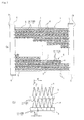
FIGS. 1] FIG. 1(a) is a front view illustrating a drain structure for a corrugated fin-type heat exchanger according to a first embodiment of the present invention, andFIG. 1(b) is an enlarged front view in the portion I ofFIG. 1(a) . - [
FIGS. 2] FIG. 2(a) is a perspective view illustrating a partial cross section of the drain structure according to the first embodiment of the present invention, andFIG. 2(b) is a partially enlarged perspective view of a corrugated fin according to the present invention. - [
FIG. 3] FIG. 3 is a perspective view illustrating a heat exchange tube having water flow passages according to the first embodiment. - [
FIG. 4] FIG. 4 is a main portion front view illustrating another form of the water flow passages according to the first embodiment. - [
FIGS. 5] FIG. 5(a) is a front view illustrating a drain structure for a corrugated fin-type heat exchanger according to a second embodiment of the present invention, andFIG. 5(b) is an enlarged front view in the portion II ofFIG. 5(a) . - [
FIG. 6] FIG. 6 is a perspective view illustrating a partial cross section of the drain structure according to the second embodiment of the present invention. - [
FIG. 7] FIG. 7 is a perspective view illustrating a heat exchange tube having water flow passages according to the second embodiment. - [
FIG. 8] FIG. 8 is a main portion front view illustrating another form of the water flow passages according to the second embodiment. - [
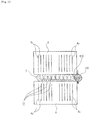
FIG. 9] FIG. 9 is a perspective view illustrating a partial cross section of a drain structure according to a third embodiment of the present invention. - [
FIG. 10] FIG. 10 is an enlarged cross-sectional view illustrating a main portion of the drain structure according to the third embodiment of the present invention. - [
FIGS. 11] FIG. 11(a) is an enlarged cross-sectional view illustrating a main portion of a drain structure according to a fourth embodiment of the present invention, andFIG. 11(b) is a side view ofFIG. 11(a) . - [
FIG. 12] FIG. 12 is an enlarged cross-sectional view illustrating a main portion of a drain structure according to a fifth embodiment of the present invention. - [
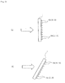
FIGS. 13] FIGS. 13 are schematic side views illustrating a form in which the drain structure of each of the third to fifth embodiments is provided on a leeward side of the heat exchanger. - [
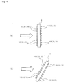
FIGS. 14] FIGS. 14 are schematic side views illustrating a form in which the drain structure of each of the third to fifth embodiments is provided on a windward side and the leeward side of the heat exchanger. - [
FIGS. 15] FIGS. 15 are schematic side views illustrating a form in which the drain structure of each of the third to fifth embodiments is provided on the windward side of the heat exchanger. - Hereinbelow, referring to the accompanying drawings, detailed description is given of embodiments of the present invention.
- As illustrated in
FIGS. 1 , a corrugated fin-type heat exchanger 1 according to the present invention includes a pair of laterallyopposing header pipes heat exchange tubes 3 bridged (continuously provided) in parallel to one another in a horizontal direction between theheader pipes fins 4 each interposed between adjacentheat exchange tubes 3, theheat exchange tubes 3 and thecorrugated fins 4 being brazed to theheader pipes heat exchange tube 3 has a plurality of sectionedheating medium passages 3a formed therein. Further, on the upper outside and the lower opening side of thecorrugated fins 4 at the upper and lower ends,side plates 5 made of aluminum are brazed, respectively. Further, at the upper and lower opening ends of theheader pipes end caps 6 made of aluminum are brazed, respectively. - In the
heat exchanger 1 having the above-mentioned configuration, as illustrated inFIGS. 1 to 3 , on a side end portion of theheat exchange tube 3 in its width direction, a flange portion 7 is provided so as to extend along a longitudinal direction of theheat exchange tube 3, andwater flow passages 10 for inducing water retained between thecorrugated fins 4 adjacent to the upper and lower sides of theheat exchange tube 3 are formed bylug pieces 8, which are, for example, obliquely cut and lugged in the flange portion 7 via cutouts at an appropriate pitch. In this case, as illustrated inFIG. 3 , the flange portions 7 may be provided so as to extend along both the end portions of the heat exchange tube to form thelug pieces 8 in the flange portions 7 via cutouts. - Note that, as illustrated in
FIG. 4 ,water flow passages 10A may be formed bylug pieces 8A, which are vertically cut and lugged with respect to theheat exchange tube 3. - In this case, when the water flow passage 10 (10A) is positioned on an outer side of the side end portion of the
corrugated fin 4, condensed water (dew water) adhering to thecorrugated fin 4 is retained between the adjacent upper and lowercorrugated fins 4. Therefore, at least part of the water flow passage 10 (10A) needs to be positioned on an inner side of the side end portion of thecorrugated fin 4. - In the
heat exchanger 1 having the above-mentioned configuration, thecorrugated fin 4 is formed by repeatedly accordion-folding a thin plate to have a predetermined height. In front view of the heat exchanger, thecorrugated fin 4 may be viewed as successive V-shapes. - The drain mechanism according to the present invention has the following configuration. Because no water passage to the lower stage is provided with respect to the condensed water (dew water), which is condensed on the surface of a V-shaped (valley-folded) fin, the condensed water moves to an adjacent inverse-V-shaped (mountain-folded) portion via
fin louvers 4c (seeFIG. 2(b) ), which are formed by cutting and lugging a plurality of longitudinal slits provided in parallel to one another in the width direction of thecorrugated fin 4. The condensed water accumulated in the inverse-V-shaped portion flows into a lowercorrugated fin 4 through a lower opening portion via the water flow passages 10 (10A) formed in theheat exchange tube 3. By smoothly repeating such a mechanism, the condensed water is prompted to be drained. - Note that, by providing the
fin louvers 4c to thecorrugated fin 4, heat exchange performance can be improved, that is, by providing a predetermined number of louvers formed in the air passage at a predetermined angle, heat transfer performance can be improved due to a turbulence effect or the like. - In this drain mechanism, when the pitch of the water flow passages 10 (10A) formed in the
heat exchange tube 3 is four times or larger than the pitch of the corrugated fin 4 (peak-to-valley dimension), the number of drain passages connecting the upper and lower sides is reduced as compared to the water retention capability of thecorrugated fins 4. Hence, the drain rate is extremely lowered, with the result that no practically effective drain effect can be obtained. Therefore, as illustrated inFIGS. 1(b) and4 , it is preferred that a pitch P1 of the water flow passages 10 (10A), that is, the lug pieces 8 (8A), be four times or smaller than a pitch P of the corrugated fin 4 (peak-to-valley dimension). - According to the drain structure having the above-mentioned configuration, when the surface of the heat exchanger becomes wet, under a state in which the condensed water (dew water) in the form of water droplets, which is condensed on the surface of the
corrugated fin 4, is retained between thecorrugated fins 4 adjacent to the upper and lower sides of theheat exchange tube 3, the edge portions of the lug pieces 8 (8A) {water flow passages 10 (10A)} are brought into contact with the retained water, and therefore serve as a water-falling origin. As a result, the water can be induced and drained to the lowercorrugated fin 4. Subsequently, in the same manner, the condensed water (dew water) in the form of water droplets, which is condensed on the surface of thecorrugated fin 4, is sequentially drained to the lowercorrugated fin 4. - The above-mentioned embodiment has described the case where the water flow passages 10 (10A) are formed by the lug pieces 8 (8A), which are obliquely or vertically cut and lugged via cutouts in the flange portion 7 provided so as to extend along the end portion of the
heat exchange tube 3 in the width direction. However, the present invention is not necessarily limited to the configuration of this embodiment. - For example, as illustrated in
FIGS. 5 to 7 , athick portion 9 may be provided to the end portion of theheat exchange tube 3 in the width direction, and agroove portion 11 may be formed by, for example, vertically cutting out thethick portion 9 over the range of from the upper side to the lower side, to thereby formwater flow passages 10B. In this case, a plurality ofgroove portions 11 are provided at an appropriate pitch P2 along the longitudinal direction of theheat exchange tube 3, and at least part of thegroove portion 11 is positioned on the inner side of the side end portion of thecorrugated fin 4. Further, the pitch P2 of thegroove portions 11, that is, thewater flow passages 10B, falls in the range of four times or smaller than the pitch P of the corrugated fin 4 (peak-to-valley dimension). In this case, as illustrated inFIG. 7 , thethick portions 9 may be provided to both the end portions of theheat exchange tube 3 in the width direction to form thewater flow passages 10B by thegroove portions 11, which are formed by cutting out thethick portion 9 over the range of from the upper side to the lower side. - Note that, as illustrated in
FIG. 8 ,water flow passages 10C may be formed by agroove portion 11A, which are formed through cutting performed obliquely to theheat exchange tube 3. - Also in this case, in order to obtain a practically effective drain effect, as illustrated in
FIGS. 5(b) and8 , it is preferred that the pitch P2 of thewater flow passages 10B (10C), that is, the groove portions 11 (11A), be four times or smaller than the pitch P of the corrugated fin 4 (peak-to-valley dimension). - According to the drain structure of the second embodiment having the above-mentioned configuration, when the surface of the heat exchanger becomes wet, under a state in which the condensed water (dew water) in the form of water droplets, which is condensed on the surface of the
corrugated fin 4, is retained between thecorrugated fins 4 adjacent to the upper and lower sides of theheat exchange tube 3, the edge portions of the groove portions 11 (11A) {water flow passages 10B (11C)} are brought into contact with the retained water, and therefore serve as a water-falling origin. As a result, the water can be induced and drained to the lowercorrugated fin 4. Subsequently, in the same manner, the condensed water (dew water) in the form of water droplets, which is condensed on the surface of thecorrugated fin 4, is sequentially drained to the lowercorrugated fin 4. - According to the drain structures of the first and second embodiments having the above-mentioned configurations, a plurality of water flow passages 10 (10A, 10B, 10C) for inducing water retained between the
corrugated fins 4 adjacent to the upper and lower sides of theheat exchange tube 3 are formed on the outer end surface of theheat exchange tube 3 in the width direction at the appropriate pitch along the longitudinal direction of theheat exchange tube 3. Thus, under the state in which the water droplets adhering to theheat exchanger 1 are retained between thecorrugated fins 4, the edge portions of the water flow passages 10 (10A, 10B, 10C) are brought into contact with the retained water, and therefore serve as the water-falling origin. As a result, the water can be induced and drained to the lowercorrugated fin 4. Accordingly, a sufficient drainage is obtained even in a case where the flatheat exchange tubes 3 are horizontally arranged. - Further, the water flow passages 10 (10A, 10B, 10C) are formed in the end portion of the
heat exchange tube 3, and hence the flow of air passing through theheat exchanger 1 is not inhibited. Thus, it is possible to suppress an adverse effect on the airflow resistance and the heat exchange efficiency. - Still further, the water flow passages 10 (10A, 10B, 10C) are formed in the
heat exchange tube 3 to provide the heat exchanger itself with the drain prompting mechanism, and hence the number of components does not need to be increased and the components can be assembled easily. As a result, theheat exchanger 1 can be manufactured easily. - Next, referring to
FIGS. 9 to 15 , description is given of drain structures according to other embodiments of the present invention. InFIGS. 9 to 15 , theheat exchanger 1 is the same as those in the above-mentioned first and second embodiments, and hence the same components are represented by the same reference symbols to omit their description. - In the
heat exchanger 1 having the above-mentioned configuration, on the side end portion of theheat exchange tube 3 in the width direction, a lineardrain assisting member 100 is arranged so as to extend along theheat exchange tube 3 and to come into contact with thecorrugated fins 4 adjacent to the upper and lower sides of theheat exchange tube 3. Thedrain assisting member 100 forms a water passage for inducing the water droplets adhering to theheat exchanger 1. In this case, thedrain assisting member 100 is formed of, for example, a single linear wire made of aluminum or a synthetic resin, and the water passage is formed by aclearance 110 between thedrain assisting member 100 and theheat exchange tube 3. - The
heat exchanger 1 having the above-mentioned configuration is generally constituted by assembling theheat exchange tubes 3, thecorrugated fins 4, and the like between theheader pipes drain assisting member 100 is formed of a wire made of aluminum, instead of the method of brazing (joining) theheat exchanger 1 itself in a normal manner and then separately fixing thedrain assisting member 100, there may be employed a method of providing thedrain assisting member 100 along theheat exchange tube 3 and then integrally brazing (joining) thedrain assisting member 100 together with the heat exchanger. Note that, in a case where thedrain assisting member 100 is formed of a wire made of a synthetic resin, theheat exchanger 1 itself is brazed (joined) and then thedrain assisting member 100 is fixed with an adhesive or the like. - According to the drain structure having the above-mentioned configuration, when the surface of the heat exchanger becomes wet, the water droplets adhering to the
corrugated fin 4 are induced to theclearance 110 between thedrain assisting member 100 and theheat exchange tube 3, and are drained to the lowercorrugated fin 4 with theclearance 110 serving as the water passage. Subsequently, in the same manner, the water droplets adhering to thecorrugated fin 4 are sequentially drained to the lowercorrugated fin 4. - The above-mentioned third embodiment has described the case where the
drain assisting member 100 is formed of a single wire, but a drain assisting member having a different shape may be used. - For example, in a fourth embodiment illustrated in
FIGS. 11 , adrain assisting member 20 has a shape in which a plurality oflinear materials 21 made of aluminum, for example, two or three linear materials 21 (FIGS. 11 illustrate a case of three linear materials 21), are twisted together, and the water passage is formed in aclearance 22 defined among the respectivelinear materials 21. In this case, theclearance 22 is positioned on the inner side of the side end of thecorrugated fin 4. - According to the structure of the fourth embodiment having the above-mentioned configuration, as illustrated in
FIG. 11(b) , by the capillary phenomenon, the water droplets adhering to thecorrugated fin 4 run into thedrain assisting member 20 arranged in the vicinity thereof from anopen peak portion 4a of a corrugated shape, that is, a peak-4a-to-valley-4b shape, and are drained to the lowercorrugated fin 4 with the gap of thedrain assisting member 20 itself, that is, theclearance 22 defined among thelinear materials 21 serving as the water passage. Subsequently, in the same manner, the water droplets adhering to thecorrugated fin 4 are sequentially drained to the lowercorrugated fin 4. - Note that, in the above-mentioned fourth embodiment, other components are the same as those in the third embodiment, and hence the same components are represented by the same reference symbols to omit their description.
- Further, in the above-mentioned third and fourth embodiments, in the case where the
drain assisting member 100 is formed of a wire made of aluminum, thedrain assisting member 100 is provided along theheat exchange tube 3 and is then integrally brazed (joined) together with the heat exchanger. - Further, in a fifth embodiment illustrated in
FIG. 12 , adrain assisting member 30 is formed of wool or a chenille-laced linear material, and the water droplets adhering to a fuzzy surface of thedrain assisting member 30 formed of the wool or chenille-laced linear material are induced to a water film or water droplets on the surface of thedrain assisting member 30. Accordingly, the water passage is formed in this surface. - According to the structure of the fifth embodiment having the above-mentioned configuration, when the
heat exchanger 1 becomes wet, the water droplets adhere to the surface of the wool or chenille-laced linear material forming thedrain assisting member 30, and further the water film is formed on the surface. Further, the water droplets adhering to thecorrugated fin 4 are induced to the water film or water droplets on the surface of the wool or chenille-laced linear material forming thedrain assisting member 30 by the capillary phenomenon, and are drained to the lowercorrugated fin 4 with the surface serving as the water passage. Subsequently, in the same manner, the water droplets adhering to thecorrugated fin 4 are sequentially drained to the lowercorrugated fin 4. Note that, other components in the fifth embodiment are the same as those in the third and fourth embodiments, and hence the same components are represented by the same reference symbols to omit their description. - The
heat exchanger 1 including the drain structure of each of the third to fifth embodiments having the above-mentioned configurations is usable in the following condition. - For example, as illustrated in
FIGS. 13 , theheat exchanger 1 is usable in such a manner that theheat exchanger 1 is vertically arranged or obliquely arranged with the upper end side of theheat exchanger 1 positioned on a leeward side, and thedrain assisting member - With this configuration, as described above, the water droplets adhering to the
heat exchanger 1 can more efficiently be drained, on the leeward side of theheat exchanger 1, from the uppercorrugated fin 4 to the lowercorrugated fin 4 while running through the water passage formed by the lowerdrain assisting member 100. - Further, as illustrated in
FIGS. 14 , theheat exchanger 1 is usable in such a manner that theheat exchanger 1 is vertically arranged or obliquely arranged with the upper end side thereof positioned on a leeward side, and thedrain assisting member 100 is arranged on the windward side and the leeward side. - With this configuration, as described above, the water droplets adhering to the
heat exchanger 1 can even more efficiently be drained, on the windward side and the leeward side of theheat exchanger 1, from the uppercorrugated fin 4 to the lowercorrugated fin 4 while running through the water passage formed by the lowerdrain assisting member 100. - Further, as illustrated in
FIGS. 15 , theheat exchanger 1 may be used in such a manner that theheat exchanger 1 is vertically arranged or obliquely arranged with the upper end side of theheat exchanger 1 positioned on a windward side, and thedrain assisting member 100 is arranged on the windward side. - With this configuration, as described above, the water droplets adhering to the
heat exchanger 1 can be drained, on the windward side of theheat exchanger 1, from the uppercorrugated fin 4 to the lowercorrugated fin 4 while running through the water passage formed by the lowerdrain assisting member 100. - According to the drain structures of the third to fifth embodiments having the above-mentioned configurations, the linear drain assisting member 100 (20 or 30) is arranged so as to extend along the
heat exchange tube 3 and to come into contact with thecorrugated fins 4 adjacent to the upper and lower sides of theheat exchange tube 3, and the drain assisting member 100 (20 or 30) forms the water passage for inducing the water droplets adhering to theheat exchanger 1, that is, the clearance 110 (22). Thus, it is possible to allow the water droplets adhering to theheat exchanger 1 to run through the uppercorrugated fin 4 to flow into the drain assisting member 100 (20 or 30) arranged along the lowerheat exchange tube 3, and to be drained to the lowercorrugated fin 4 via the clearance 110 (22) formed by the drain assisting member 100 (20 or 30). Accordingly, a sufficient drainage is obtained even in the case where the flatheat exchange tubes 3 are horizontally arranged. - Further, the drain assisting member 100 (20 or 30) is arranged along the
heat exchange tube 3, and hence the flow of air passing through theheat exchanger 1 is not inhibited by the added drain assisting member itself. Thus, it is possible to suppress the adverse effect on the airflow resistance and the heat exchange efficiency. - Still further, the drain assisting member 100 (20 or 30) can be assembled to the
heat exchanger 1 more easily than in the case where a linear material such as a wire is obliquely arranged on the surface of the heat exchanger. Further, in the case where the drain assisting member 100 (20) is formed of a wire made of aluminum, the drain assisting member 100 (20) can integrally be brazed (joined) together with theheat exchanger 1. As a result, theheat exchanger 1 can be manufactured easily. - The present invention is useful when used in an evaporator. However, even in a parallel flow corrugated fin-type heat exchanger other than the evaporator, it is possible to provide a sufficient drainage of water droplets adhering to a surface thereof to suppress an adverse effect on an airflow resistance and a heat exchange efficiency, even in a case where heat exchange tubes are arranged horizontally.
-
- 1
- heat exchanger
- 2a, 2b
- header pipe
- 3
- heat exchange tube
- 4
- corrugated fin
- 4c
- fin louver
- 7
- flange portion
- 8, 8A
- lug piece
- 9
- thick portion
- 10, 10A, 10B, 10C
- water flow passage
- 11, 11A
- groove portion
- P
- pitch of corrugated fin
- P1
- pitch of lug pieces
- P2
- pitch of groove portions
- 100
- drain assisting member
- 110
- clearance
- 20
- drain assisting member
- 21
- linear material
- 22
- clearance
- 30
- drain assisting member (wool, chenille-laced linear material)
Claims (13)
- A drain structure for a corrugated fin-type heat exchanger,
the corrugated fin-type heat exchanger being constituted by arranging a plurality of flat heat exchange tubes parallel to one another in a horizontal direction between a pair of opposing header pipes, and joining corrugated fins between the plurality of flat heat exchange tubes,
the drain structure comprising a plurality of water flow passages for inducing water retained between the corrugated fins adjacent to an upper side and a lower side of each of the plurality of flat heat exchange tubes, the plurality of water flow passages being formed on an outer end surface of the each of the plurality of flat heat exchange tubes in a width direction thereof at a pitch along a longitudinal direction of the each of the plurality of flat heat exchange tubes. - A drain structure for a corrugated fin-type heat exchanger according to claim 1, wherein the plurality of water flow passages are each formed by lug pieces, which are obliquely or vertically cut and lugged in a flange portion provided so as to extend along an end portion of the each of the plurality of flat heat exchange tubes in the width direction.
- A drain structure for a corrugated fin-type heat exchanger according to claim 1, wherein the plurality of water flow passages are each formed by a groove portion, which is formed in an end portion of the each of the plurality of flat heat exchange tubes in the width direction through cutting performed obliquely or vertically over a range of from the upper side to the lower side.
- A drain structure for a corrugated fin-type heat exchanger according to any one of claims 1 to 3, wherein at least part of each of the plurality of water flow passages is positioned on an inner side of a side end portion of each of the corrugated fins.
- A drain structure for a corrugated fin-type heat exchanger according to any one of claims 1 to 4, wherein the pitch of the plurality of water flow passages is in a range of four times or smaller than a pitch of each of the corrugated fins.
- A drain structure for a corrugated fin-type heat exchanger,
the corrugated fin-type heat exchanger being constituted by arranging a plurality of flat heat exchange tubes parallel to one another in a horizontal direction between a pair of opposing header pipes, and joining corrugated fins between the plurality of flat heat exchange tubes,
the drain structure comprising a water passage for inducing water droplets adhering to the corrugated fin-type heat exchanger, the water passage being formed by a linear drain assisting member, which is arranged so as to extend along each of the plurality of flat heat exchange tubes and to come into contact with the corrugated fins adjacent to an upper side and a lower side of the each of the plurality of flat heat exchange tubes. - A drain structure for a corrugated fin-type heat exchanger according to claim 6, wherein the linear drain assisting member comprises a wire arranged to define a fine clearance so as to form the water passage between the wire and the each of the plurality of flat heat exchange tubes.
- A drain structure for a corrugated fin-type heat exchanger according to claim 6,
wherein the linear drain assisting member has a shape in which a plurality of linear materials are twisted together, and
wherein the water passage is formed in a clearance defined among the plurality of linear materials, and the clearance is positioned on an inner side of a side end of each of the corrugated fins. - A drain structure for a corrugated fin-type heat exchanger according to claim 7 or 8, wherein the linear drain assisting member is formed of the same material forming the corrugated fin-type heat exchanger, and is integrally joined to the corrugated fin-type heat exchanger by brazing.
- A drain structure for a corrugated fin-type heat exchanger according to claim 6,
wherein the linear drain assisting member comprises wool or a chenille-laced linear material, and
wherein water droplets adhering to a surface of the wool or the chenille-laced linear material are induced to a water film or water droplets on a surface of the linear drain assisting member, and the water passage is formed in the surface. - A drain structure for a corrugated fin-type heat exchanger according to any one of claims 6 to 10, wherein the corrugated fin-type heat exchanger is vertically arranged or obliquely arranged with an upper end side of the corrugated fin-type heat exchanger positioned on a leeward side, and the linear drain assisting member is arranged on the leeward side.
- A drain structure for a corrugated fin-type heat exchanger according to any one of claims 6 to 10, wherein the corrugated fin-type heat exchanger is vertically arranged or obliquely arranged with an upper end side of the corrugated fin-type heat exchanger positioned on a leeward side, and the linear drain assisting member is arranged on a windward side and the leeward side.
- A drain structure for a corrugated fin-type heat exchanger according to any one of claims 6 to 10, wherein the corrugated fin-type heat exchanger is vertically arranged or obliquely arranged with an upper end side of the corrugated fin-type heat exchanger positioned on a windward side, and the linear drain assisting member is arranged on the windward side.
Priority Applications (1)
| Application Number | Priority Date | Filing Date | Title |
|---|---|---|---|
| EP14183933.2A EP2824403A1 (en) | 2009-03-17 | 2010-03-08 | Drainage structure of corrugated fin-type heat exchanger |
Applications Claiming Priority (3)
| Application Number | Priority Date | Filing Date | Title |
|---|---|---|---|
| JP2009064876 | 2009-03-17 | ||
| JP2009069372 | 2009-03-23 | ||
| PCT/JP2010/001624 WO2010106757A1 (en) | 2009-03-17 | 2010-03-08 | Drainage structure of corrugated fin-type heat exchanger |
Related Child Applications (2)
| Application Number | Title | Priority Date | Filing Date |
|---|---|---|---|
| EP14183933.2A Division EP2824403A1 (en) | 2009-03-17 | 2010-03-08 | Drainage structure of corrugated fin-type heat exchanger |
| EP14183933.2A Division-Into EP2824403A1 (en) | 2009-03-17 | 2010-03-08 | Drainage structure of corrugated fin-type heat exchanger |
Publications (3)
| Publication Number | Publication Date |
|---|---|
| EP2410266A1 true EP2410266A1 (en) | 2012-01-25 |
| EP2410266A4 EP2410266A4 (en) | 2014-02-26 |
| EP2410266B1 EP2410266B1 (en) | 2016-01-13 |
Family
ID=42739425
Family Applications (2)
| Application Number | Title | Priority Date | Filing Date |
|---|---|---|---|
| EP10753254.1A Active EP2410266B1 (en) | 2009-03-17 | 2010-03-08 | Drainage structure of corrugated fin-type heat exchanger |
| EP14183933.2A Withdrawn EP2824403A1 (en) | 2009-03-17 | 2010-03-08 | Drainage structure of corrugated fin-type heat exchanger |
Family Applications After (1)
| Application Number | Title | Priority Date | Filing Date |
|---|---|---|---|
| EP14183933.2A Withdrawn EP2824403A1 (en) | 2009-03-17 | 2010-03-08 | Drainage structure of corrugated fin-type heat exchanger |
Country Status (7)
| Country | Link |
|---|---|
| US (1) | US9328975B2 (en) |
| EP (2) | EP2410266B1 (en) |
| KR (2) | KR101383508B1 (en) |
| CN (2) | CN102356287A (en) |
| AU (1) | AU2010226063B2 (en) |
| EG (1) | EG26918A (en) |
| WO (1) | WO2010106757A1 (en) |
Cited By (1)
| Publication number | Priority date | Publication date | Assignee | Title |
|---|---|---|---|---|
| CN105091413A (en) * | 2014-05-06 | 2015-11-25 | 美的集团股份有限公司 | Heat exchanger |
Families Citing this family (15)
| Publication number | Priority date | Publication date | Assignee | Title |
|---|---|---|---|---|
| JP5550106B2 (en) * | 2009-03-17 | 2014-07-16 | 日本軽金属株式会社 | Corrugated fin heat exchanger drainage structure |
| JP4503682B1 (en) * | 2009-04-22 | 2010-07-14 | シャープ株式会社 | Heat exchanger and air conditioner equipped with the same |
| JP2012093010A (en) * | 2010-10-25 | 2012-05-17 | Sharp Corp | Heat exchanger and air conditioner mounted with the same |
| CN103180684B (en) * | 2010-10-25 | 2015-12-16 | 夏普株式会社 | Heat exchanger and the air conditioner being provided with heat exchanger |
| JP5009409B2 (en) * | 2010-10-25 | 2012-08-22 | シャープ株式会社 | Heat exchanger and air conditioner equipped with the same |
| JP5678392B2 (en) * | 2011-06-16 | 2015-03-04 | 日本軽金属株式会社 | Corrugated fin heat exchanger drainage structure |
| JP6016212B2 (en) * | 2012-10-16 | 2016-10-26 | 日本軽金属株式会社 | Corrugated fin heat exchanger drainage structure |
| US20150144309A1 (en) * | 2013-03-13 | 2015-05-28 | Brayton Energy, Llc | Flattened Envelope Heat Exchanger |
| JP6455940B2 (en) * | 2013-04-24 | 2019-01-23 | デーナ、カナダ、コーパレイシャン | Fin support structure for charge air cooler |
| CN104236332A (en) * | 2014-08-27 | 2014-12-24 | 杭州三花微通道换热器有限公司 | Heat exchanger |
| JP6463479B2 (en) | 2015-07-29 | 2019-02-06 | 三菱電機株式会社 | Heat exchanger and refrigeration cycle apparatus |
| WO2017221303A1 (en) * | 2016-06-20 | 2017-12-28 | 三菱電機株式会社 | Heat exchanger, and heat pump device equipped with heat exchanger |
| US9945618B1 (en) * | 2017-01-04 | 2018-04-17 | Wieland Copper Products, Llc | Heat transfer surface |
| KR102676854B1 (en) * | 2018-12-27 | 2024-06-21 | 삼성전자주식회사 | Outdoor display device |
| CN113144682A (en) * | 2021-04-23 | 2021-07-23 | 龙海市仁吉建材有限公司 | Settling post-treatment method for stone powder residues after stone processing |
Family Cites Families (19)
| Publication number | Priority date | Publication date | Assignee | Title |
|---|---|---|---|---|
| US3832965A (en) * | 1973-07-17 | 1974-09-03 | P Walker | Submersible transport apparatus |
| JPS6193453U (en) * | 1984-11-26 | 1986-06-17 | ||
| JPH0664309B2 (en) * | 1986-03-04 | 1994-08-22 | コニカ株式会社 | Silver halide photosensitive material sensitized in the presence of silver halide solvent |
| JPS62204251U (en) | 1986-06-18 | 1987-12-26 | ||
| JPH04324093A (en) | 1991-04-23 | 1992-11-13 | Asahi Chem Ind Co Ltd | Pin-fin heat exchanger |
| JPH09101092A (en) * | 1995-10-04 | 1997-04-15 | Calsonic Corp | Evaporator |
| JPH10318695A (en) * | 1997-05-19 | 1998-12-04 | Zexel Corp | Heat exchanger |
| JP2000241093A (en) * | 1999-02-24 | 2000-09-08 | Daikin Ind Ltd | Air heat exchanger |
| EP1035398B1 (en) * | 1999-03-05 | 2004-01-14 | Denso Corporation | Cooling apparatus using boiling and condensing refrigerant |
| JP2001263861A (en) | 2000-03-17 | 2001-09-26 | Sanyo Electric Co Ltd | Heat exchanger |
| KR20040017920A (en) | 2002-08-22 | 2004-03-02 | 엘지전자 주식회사 | Condensate drainage of heat exchanger |
| WO2006070918A1 (en) * | 2004-12-28 | 2006-07-06 | Showa Denko K.K. | Evaporator |
| FR2891901B1 (en) * | 2005-10-06 | 2014-03-14 | Air Liquide | METHOD FOR VAPORIZATION AND / OR CONDENSATION IN A HEAT EXCHANGER |
| JP2007183029A (en) * | 2006-01-05 | 2007-07-19 | T Rad Co Ltd | Latent heat recovery heat exchanger |
| JP2007285673A (en) | 2006-04-20 | 2007-11-01 | Yanmar Co Ltd | Drain structure for corrugated type heat exchanger |
| CN101568782A (en) * | 2006-12-26 | 2009-10-28 | 开利公司 | Heat exchanger with improved condensate removal |
| CN100498187C (en) * | 2007-01-15 | 2009-06-10 | 高克联管件(上海)有限公司 | Evaporation and condensation combined type heat-transfer pipe |
| CN101275788B (en) | 2007-03-29 | 2012-06-06 | 三洋电机株式会社 | Apparatus including freezing unit and projector including freezing unit |
| JP2010025477A (en) * | 2008-07-22 | 2010-02-04 | Daikin Ind Ltd | Heat exchanger |
-
2010
- 2010-03-08 KR KR1020137029033A patent/KR101383508B1/en not_active Expired - Fee Related
- 2010-03-08 EP EP10753254.1A patent/EP2410266B1/en active Active
- 2010-03-08 WO PCT/JP2010/001624 patent/WO2010106757A1/en not_active Ceased
- 2010-03-08 EP EP14183933.2A patent/EP2824403A1/en not_active Withdrawn
- 2010-03-08 CN CN2010800127017A patent/CN102356287A/en active Pending
- 2010-03-08 CN CN201310353983.2A patent/CN103471452B/en not_active Expired - Fee Related
- 2010-03-08 US US13/257,230 patent/US9328975B2/en active Active
- 2010-03-08 AU AU2010226063A patent/AU2010226063B2/en not_active Ceased
- 2010-03-08 KR KR1020117021638A patent/KR101419103B1/en active Active
-
2011
- 2011-09-15 EG EG2011091539A patent/EG26918A/en active
Cited By (2)
| Publication number | Priority date | Publication date | Assignee | Title |
|---|---|---|---|---|
| CN105091413A (en) * | 2014-05-06 | 2015-11-25 | 美的集团股份有限公司 | Heat exchanger |
| CN105091413B (en) * | 2014-05-06 | 2017-10-13 | 美的集团股份有限公司 | Heat exchanger |
Also Published As
| Publication number | Publication date |
|---|---|
| US20120272677A1 (en) | 2012-11-01 |
| EP2824403A1 (en) | 2015-01-14 |
| EG26918A (en) | 2014-12-21 |
| WO2010106757A1 (en) | 2010-09-23 |
| EP2410266A4 (en) | 2014-02-26 |
| CN103471452A (en) | 2013-12-25 |
| EP2410266B1 (en) | 2016-01-13 |
| AU2010226063B2 (en) | 2013-07-11 |
| KR20120004411A (en) | 2012-01-12 |
| US9328975B2 (en) | 2016-05-03 |
| AU2010226063A1 (en) | 2011-09-29 |
| KR101419103B1 (en) | 2014-07-11 |
| CN102356287A (en) | 2012-02-15 |
| CN103471452B (en) | 2016-01-20 |
| KR20140003627A (en) | 2014-01-09 |
| KR101383508B1 (en) | 2014-04-08 |
Similar Documents
| Publication | Publication Date | Title |
|---|---|---|
| EP2410266B1 (en) | Drainage structure of corrugated fin-type heat exchanger | |
| JP5678392B2 (en) | Corrugated fin heat exchanger drainage structure | |
| CN102047064B (en) | Heat exchanger | |
| JP5550106B2 (en) | Corrugated fin heat exchanger drainage structure | |
| US8613307B2 (en) | Finned tube heat exchanger | |
| CN103238038B (en) | Microchannel Heat Exchanger Fins | |
| US20200011607A1 (en) | Heat exchanger including heat-transfer-tube unit | |
| JP5869665B2 (en) | Heat exchanger | |
| JP6375897B2 (en) | Heat exchanger | |
| WO2013157212A1 (en) | Fin-tube heat exchanger | |
| JPWO2012102053A1 (en) | Finned tube heat exchanger | |
| CN100554855C (en) | Fin tube heat exchanger | |
| CN110741217A (en) | Heat Exchangers and Corrugated Fins | |
| JP5447842B2 (en) | Corrugated fin heat exchanger drainage structure | |
| JP2012251719A (en) | Drainage structure of corrugated fin type heat exchanger | |
| JPH0545474U (en) | Heat exchanger | |
| JP2010065892A (en) | Heat exchanger | |
| JP2012083070A (en) | Drainage structure of corrugated fin-type heat exchanger | |
| JP2010025480A (en) | Heat exchanger and method for manufacturing the heat exchanger | |
| JP7263970B2 (en) | Heat exchanger | |
| JPH07294173A (en) | Mesh fin heat exchanger for air conditioner | |
| KR20110059107A (en) | Fin for heat exchanger |
Legal Events
| Date | Code | Title | Description |
|---|---|---|---|
| PUAI | Public reference made under article 153(3) epc to a published international application that has entered the european phase |
Free format text: ORIGINAL CODE: 0009012 |
|
| 17P | Request for examination filed |
Effective date: 20111012 |
|
| AK | Designated contracting states |
Kind code of ref document: A1 Designated state(s): AT BE BG CH CY CZ DE DK EE ES FI FR GB GR HR HU IE IS IT LI LT LU LV MC MK MT NL NO PL PT RO SE SI SK SM TR |
|
| DAX | Request for extension of the european patent (deleted) | ||
| RAP1 | Party data changed (applicant data changed or rights of an application transferred) |
Owner name: NIPPON LIGHT METAL COMPANY, LTD. Owner name: SHARP KABUSHIKI KAISHA |
|
| A4 | Supplementary search report drawn up and despatched |
Effective date: 20140127 |
|
| RIC1 | Information provided on ipc code assigned before grant |
Ipc: F28F 17/00 20060101ALI20140121BHEP Ipc: F28F 1/26 20060101ALI20140121BHEP Ipc: F25B 39/02 20060101AFI20140121BHEP Ipc: F28F 1/30 20060101ALI20140121BHEP |
|
| GRAP | Despatch of communication of intention to grant a patent |
Free format text: ORIGINAL CODE: EPIDOSNIGR1 |
|
| INTG | Intention to grant announced |
Effective date: 20150611 |
|
| GRAS | Grant fee paid |
Free format text: ORIGINAL CODE: EPIDOSNIGR3 |
|
| GRAA | (expected) grant |
Free format text: ORIGINAL CODE: 0009210 |
|
| RAP1 | Party data changed (applicant data changed or rights of an application transferred) |
Owner name: NIPPON LIGHT METAL COMPANY, LTD. |
|
| AK | Designated contracting states |
Kind code of ref document: B1 Designated state(s): AT BE BG CH CY CZ DE DK EE ES FI FR GB GR HR HU IE IS IT LI LT LU LV MC MK MT NL NO PL PT RO SE SI SK SM TR |
|
| REG | Reference to a national code |
Ref country code: GB Ref legal event code: FG4D |
|
| REG | Reference to a national code |
Ref country code: CH Ref legal event code: EP |
|
| REG | Reference to a national code |
Ref country code: IE Ref legal event code: FG4D |
|
| REG | Reference to a national code |
Ref country code: AT Ref legal event code: REF Ref document number: 770796 Country of ref document: AT Kind code of ref document: T Effective date: 20160215 |
|
| REG | Reference to a national code |
Ref country code: DE Ref legal event code: R096 Ref document number: 602010030179 Country of ref document: DE |
|
| REG | Reference to a national code |
Ref country code: FR Ref legal event code: PLFP Year of fee payment: 7 |
|
| REG | Reference to a national code |
Ref country code: LT Ref legal event code: MG4D |
|
| REG | Reference to a national code |
Ref country code: NL Ref legal event code: MP Effective date: 20160113 |
|
| REG | Reference to a national code |
Ref country code: AT Ref legal event code: MK05 Ref document number: 770796 Country of ref document: AT Kind code of ref document: T Effective date: 20160113 |
|
| PG25 | Lapsed in a contracting state [announced via postgrant information from national office to epo] |
Ref country code: NL Free format text: LAPSE BECAUSE OF FAILURE TO SUBMIT A TRANSLATION OF THE DESCRIPTION OR TO PAY THE FEE WITHIN THE PRESCRIBED TIME-LIMIT Effective date: 20160113 |
|
| PG25 | Lapsed in a contracting state [announced via postgrant information from national office to epo] |
Ref country code: GR Free format text: LAPSE BECAUSE OF FAILURE TO SUBMIT A TRANSLATION OF THE DESCRIPTION OR TO PAY THE FEE WITHIN THE PRESCRIBED TIME-LIMIT Effective date: 20160414 Ref country code: HR Free format text: LAPSE BECAUSE OF FAILURE TO SUBMIT A TRANSLATION OF THE DESCRIPTION OR TO PAY THE FEE WITHIN THE PRESCRIBED TIME-LIMIT Effective date: 20160113 Ref country code: ES Free format text: LAPSE BECAUSE OF FAILURE TO SUBMIT A TRANSLATION OF THE DESCRIPTION OR TO PAY THE FEE WITHIN THE PRESCRIBED TIME-LIMIT Effective date: 20160113 Ref country code: IT Free format text: LAPSE BECAUSE OF FAILURE TO SUBMIT A TRANSLATION OF THE DESCRIPTION OR TO PAY THE FEE WITHIN THE PRESCRIBED TIME-LIMIT Effective date: 20160113 Ref country code: NO Free format text: LAPSE BECAUSE OF FAILURE TO SUBMIT A TRANSLATION OF THE DESCRIPTION OR TO PAY THE FEE WITHIN THE PRESCRIBED TIME-LIMIT Effective date: 20160413 Ref country code: FI Free format text: LAPSE BECAUSE OF FAILURE TO SUBMIT A TRANSLATION OF THE DESCRIPTION OR TO PAY THE FEE WITHIN THE PRESCRIBED TIME-LIMIT Effective date: 20160113 |
|
| PG25 | Lapsed in a contracting state [announced via postgrant information from national office to epo] |
Ref country code: PL Free format text: LAPSE BECAUSE OF FAILURE TO SUBMIT A TRANSLATION OF THE DESCRIPTION OR TO PAY THE FEE WITHIN THE PRESCRIBED TIME-LIMIT Effective date: 20160113 Ref country code: LT Free format text: LAPSE BECAUSE OF FAILURE TO SUBMIT A TRANSLATION OF THE DESCRIPTION OR TO PAY THE FEE WITHIN THE PRESCRIBED TIME-LIMIT Effective date: 20160113 Ref country code: PT Free format text: LAPSE BECAUSE OF FAILURE TO SUBMIT A TRANSLATION OF THE DESCRIPTION OR TO PAY THE FEE WITHIN THE PRESCRIBED TIME-LIMIT Effective date: 20160513 Ref country code: SE Free format text: LAPSE BECAUSE OF FAILURE TO SUBMIT A TRANSLATION OF THE DESCRIPTION OR TO PAY THE FEE WITHIN THE PRESCRIBED TIME-LIMIT Effective date: 20160113 Ref country code: BE Free format text: LAPSE BECAUSE OF NON-PAYMENT OF DUE FEES Effective date: 20160331 Ref country code: IS Free format text: LAPSE BECAUSE OF FAILURE TO SUBMIT A TRANSLATION OF THE DESCRIPTION OR TO PAY THE FEE WITHIN THE PRESCRIBED TIME-LIMIT Effective date: 20160513 Ref country code: LV Free format text: LAPSE BECAUSE OF FAILURE TO SUBMIT A TRANSLATION OF THE DESCRIPTION OR TO PAY THE FEE WITHIN THE PRESCRIBED TIME-LIMIT Effective date: 20160113 Ref country code: AT Free format text: LAPSE BECAUSE OF FAILURE TO SUBMIT A TRANSLATION OF THE DESCRIPTION OR TO PAY THE FEE WITHIN THE PRESCRIBED TIME-LIMIT Effective date: 20160113 |
|
| REG | Reference to a national code |
Ref country code: DE Ref legal event code: R097 Ref document number: 602010030179 Country of ref document: DE |
|
| PG25 | Lapsed in a contracting state [announced via postgrant information from national office to epo] |
Ref country code: MC Free format text: LAPSE BECAUSE OF FAILURE TO SUBMIT A TRANSLATION OF THE DESCRIPTION OR TO PAY THE FEE WITHIN THE PRESCRIBED TIME-LIMIT Effective date: 20160113 Ref country code: EE Free format text: LAPSE BECAUSE OF FAILURE TO SUBMIT A TRANSLATION OF THE DESCRIPTION OR TO PAY THE FEE WITHIN THE PRESCRIBED TIME-LIMIT Effective date: 20160113 Ref country code: DK Free format text: LAPSE BECAUSE OF FAILURE TO SUBMIT A TRANSLATION OF THE DESCRIPTION OR TO PAY THE FEE WITHIN THE PRESCRIBED TIME-LIMIT Effective date: 20160113 Ref country code: LU Free format text: LAPSE BECAUSE OF FAILURE TO SUBMIT A TRANSLATION OF THE DESCRIPTION OR TO PAY THE FEE WITHIN THE PRESCRIBED TIME-LIMIT Effective date: 20160308 |
|
| REG | Reference to a national code |
Ref country code: CH Ref legal event code: PL |
|
| PLBE | No opposition filed within time limit |
Free format text: ORIGINAL CODE: 0009261 |
|
| STAA | Information on the status of an ep patent application or granted ep patent |
Free format text: STATUS: NO OPPOSITION FILED WITHIN TIME LIMIT |
|
| PG25 | Lapsed in a contracting state [announced via postgrant information from national office to epo] |
Ref country code: CZ Free format text: LAPSE BECAUSE OF FAILURE TO SUBMIT A TRANSLATION OF THE DESCRIPTION OR TO PAY THE FEE WITHIN THE PRESCRIBED TIME-LIMIT Effective date: 20160113 Ref country code: SM Free format text: LAPSE BECAUSE OF FAILURE TO SUBMIT A TRANSLATION OF THE DESCRIPTION OR TO PAY THE FEE WITHIN THE PRESCRIBED TIME-LIMIT Effective date: 20160113 Ref country code: RO Free format text: LAPSE BECAUSE OF FAILURE TO SUBMIT A TRANSLATION OF THE DESCRIPTION OR TO PAY THE FEE WITHIN THE PRESCRIBED TIME-LIMIT Effective date: 20160113 Ref country code: SK Free format text: LAPSE BECAUSE OF FAILURE TO SUBMIT A TRANSLATION OF THE DESCRIPTION OR TO PAY THE FEE WITHIN THE PRESCRIBED TIME-LIMIT Effective date: 20160113 |
|
| 26N | No opposition filed |
Effective date: 20161014 |
|
| GBPC | Gb: european patent ceased through non-payment of renewal fee |
Effective date: 20160413 |
|
| REG | Reference to a national code |
Ref country code: IE Ref legal event code: MM4A |
|
| PG25 | Lapsed in a contracting state [announced via postgrant information from national office to epo] |
Ref country code: BE Free format text: LAPSE BECAUSE OF FAILURE TO SUBMIT A TRANSLATION OF THE DESCRIPTION OR TO PAY THE FEE WITHIN THE PRESCRIBED TIME-LIMIT Effective date: 20160113 |
|
| PG25 | Lapsed in a contracting state [announced via postgrant information from national office to epo] |
Ref country code: GB Free format text: LAPSE BECAUSE OF NON-PAYMENT OF DUE FEES Effective date: 20160413 Ref country code: IE Free format text: LAPSE BECAUSE OF NON-PAYMENT OF DUE FEES Effective date: 20160308 Ref country code: CH Free format text: LAPSE BECAUSE OF NON-PAYMENT OF DUE FEES Effective date: 20160331 Ref country code: LI Free format text: LAPSE BECAUSE OF NON-PAYMENT OF DUE FEES Effective date: 20160331 |
|
| PG25 | Lapsed in a contracting state [announced via postgrant information from national office to epo] |
Ref country code: SI Free format text: LAPSE BECAUSE OF FAILURE TO SUBMIT A TRANSLATION OF THE DESCRIPTION OR TO PAY THE FEE WITHIN THE PRESCRIBED TIME-LIMIT Effective date: 20160113 Ref country code: BG Free format text: LAPSE BECAUSE OF FAILURE TO SUBMIT A TRANSLATION OF THE DESCRIPTION OR TO PAY THE FEE WITHIN THE PRESCRIBED TIME-LIMIT Effective date: 20160413 |
|
| REG | Reference to a national code |
Ref country code: FR Ref legal event code: PLFP Year of fee payment: 8 |
|
| PG25 | Lapsed in a contracting state [announced via postgrant information from national office to epo] |
Ref country code: MT Free format text: LAPSE BECAUSE OF FAILURE TO SUBMIT A TRANSLATION OF THE DESCRIPTION OR TO PAY THE FEE WITHIN THE PRESCRIBED TIME-LIMIT Effective date: 20160113 |
|
| REG | Reference to a national code |
Ref country code: FR Ref legal event code: PLFP Year of fee payment: 9 |
|
| PG25 | Lapsed in a contracting state [announced via postgrant information from national office to epo] |
Ref country code: CY Free format text: LAPSE BECAUSE OF FAILURE TO SUBMIT A TRANSLATION OF THE DESCRIPTION OR TO PAY THE FEE WITHIN THE PRESCRIBED TIME-LIMIT Effective date: 20160113 Ref country code: HU Free format text: LAPSE BECAUSE OF FAILURE TO SUBMIT A TRANSLATION OF THE DESCRIPTION OR TO PAY THE FEE WITHIN THE PRESCRIBED TIME-LIMIT; INVALID AB INITIO Effective date: 20100308 |
|
| PG25 | Lapsed in a contracting state [announced via postgrant information from national office to epo] |
Ref country code: MT Free format text: LAPSE BECAUSE OF FAILURE TO SUBMIT A TRANSLATION OF THE DESCRIPTION OR TO PAY THE FEE WITHIN THE PRESCRIBED TIME-LIMIT Effective date: 20160331 Ref country code: TR Free format text: LAPSE BECAUSE OF FAILURE TO SUBMIT A TRANSLATION OF THE DESCRIPTION OR TO PAY THE FEE WITHIN THE PRESCRIBED TIME-LIMIT Effective date: 20160113 Ref country code: MK Free format text: LAPSE BECAUSE OF FAILURE TO SUBMIT A TRANSLATION OF THE DESCRIPTION OR TO PAY THE FEE WITHIN THE PRESCRIBED TIME-LIMIT Effective date: 20160113 |
|
| P01 | Opt-out of the competence of the unified patent court (upc) registered |
Effective date: 20230519 |
|
| PGFP | Annual fee paid to national office [announced via postgrant information from national office to epo] |
Ref country code: DE Payment date: 20260319 Year of fee payment: 17 |
|
| PGFP | Annual fee paid to national office [announced via postgrant information from national office to epo] |
Ref country code: FR Payment date: 20260320 Year of fee payment: 17 |