EP2410241A1 - Heat exchanger - Google Patents
Heat exchanger Download PDFInfo
- Publication number
- EP2410241A1 EP2410241A1 EP09841901A EP09841901A EP2410241A1 EP 2410241 A1 EP2410241 A1 EP 2410241A1 EP 09841901 A EP09841901 A EP 09841901A EP 09841901 A EP09841901 A EP 09841901A EP 2410241 A1 EP2410241 A1 EP 2410241A1
- Authority
- EP
- European Patent Office
- Prior art keywords
- heat
- tube
- bare
- transfer tube
- heat exchanger
- Prior art date
- Legal status (The legal status is an assumption and is not a legal conclusion. Google has not performed a legal analysis and makes no representation as to the accuracy of the status listed.)
- Withdrawn
Links
- 230000001105 regulatory effect Effects 0.000 claims abstract description 83
- UGFAIRIUMAVXCW-UHFFFAOYSA-N Carbon monoxide Chemical compound [O+]#[C-] UGFAIRIUMAVXCW-UHFFFAOYSA-N 0.000 claims abstract description 38
- 239000003546 flue gas Substances 0.000 claims abstract description 38
- 238000011144 upstream manufacturing Methods 0.000 claims abstract description 17
- 238000010438 heat treatment Methods 0.000 claims description 12
- 238000011084 recovery Methods 0.000 description 20
- 239000007789 gas Substances 0.000 description 8
- MWUXSHHQAYIFBG-UHFFFAOYSA-N nitrogen oxide Inorganic materials O=[N] MWUXSHHQAYIFBG-UHFFFAOYSA-N 0.000 description 7
- 238000006477 desulfuration reaction Methods 0.000 description 4
- 230000023556 desulfurization Effects 0.000 description 4
- 230000003628 erosive effect Effects 0.000 description 4
- 239000003245 coal Substances 0.000 description 3
- 238000002485 combustion reaction Methods 0.000 description 3
- 239000000428 dust Substances 0.000 description 3
- 229910052815 sulfur oxide Inorganic materials 0.000 description 3
- IJGRMHOSHXDMSA-UHFFFAOYSA-N Atomic nitrogen Chemical compound N#N IJGRMHOSHXDMSA-UHFFFAOYSA-N 0.000 description 2
- 239000010883 coal ash Substances 0.000 description 2
- 238000010586 diagram Methods 0.000 description 2
- 239000012716 precipitator Substances 0.000 description 2
- 239000007787 solid Substances 0.000 description 2
- 239000004071 soot Substances 0.000 description 2
- XLYOFNOQVPJJNP-UHFFFAOYSA-N water Substances O XLYOFNOQVPJJNP-UHFFFAOYSA-N 0.000 description 2
- QGZKDVFQNNGYKY-UHFFFAOYSA-N Ammonia Chemical compound N QGZKDVFQNNGYKY-UHFFFAOYSA-N 0.000 description 1
- QGZKDVFQNNGYKY-UHFFFAOYSA-O Ammonium Chemical compound [NH4+] QGZKDVFQNNGYKY-UHFFFAOYSA-O 0.000 description 1
- 235000019738 Limestone Nutrition 0.000 description 1
- 239000000809 air pollutant Substances 0.000 description 1
- 231100001243 air pollutant Toxicity 0.000 description 1
- 239000002956 ash Substances 0.000 description 1
- 239000006227 byproduct Substances 0.000 description 1
- 239000003054 catalyst Substances 0.000 description 1
- 239000003638 chemical reducing agent Substances 0.000 description 1
- 230000000694 effects Effects 0.000 description 1
- 239000000446 fuel Substances 0.000 description 1
- 239000010440 gypsum Substances 0.000 description 1
- 229910052602 gypsum Inorganic materials 0.000 description 1
- 239000006028 limestone Substances 0.000 description 1
- 238000012423 maintenance Methods 0.000 description 1
- 230000004048 modification Effects 0.000 description 1
- 238000012986 modification Methods 0.000 description 1
- 229910052757 nitrogen Inorganic materials 0.000 description 1
- 239000003208 petroleum Substances 0.000 description 1
- 238000010248 power generation Methods 0.000 description 1
- 239000000779 smoke Substances 0.000 description 1
- XTQHKBHJIVJGKJ-UHFFFAOYSA-N sulfur monoxide Chemical class S=O XTQHKBHJIVJGKJ-UHFFFAOYSA-N 0.000 description 1
Images



Classifications
-
- F—MECHANICAL ENGINEERING; LIGHTING; HEATING; WEAPONS; BLASTING
- F22—STEAM GENERATION
- F22B—METHODS OF STEAM GENERATION; STEAM BOILERS
- F22B37/00—Component parts or details of steam boilers
- F22B37/02—Component parts or details of steam boilers applicable to more than one kind or type of steam boiler
- F22B37/40—Arrangements of partition walls in flues of steam boilers, e.g. built-up from baffles
-
- F—MECHANICAL ENGINEERING; LIGHTING; HEATING; WEAPONS; BLASTING
- F22—STEAM GENERATION
- F22B—METHODS OF STEAM GENERATION; STEAM BOILERS
- F22B1/00—Methods of steam generation characterised by form of heating method
- F22B1/02—Methods of steam generation characterised by form of heating method by exploitation of the heat content of hot heat carriers
- F22B1/18—Methods of steam generation characterised by form of heating method by exploitation of the heat content of hot heat carriers the heat carrier being a hot gas, e.g. waste gas such as exhaust gas of internal-combustion engines
-
- F—MECHANICAL ENGINEERING; LIGHTING; HEATING; WEAPONS; BLASTING
- F23—COMBUSTION APPARATUS; COMBUSTION PROCESSES
- F23J—REMOVAL OR TREATMENT OF COMBUSTION PRODUCTS OR COMBUSTION RESIDUES; FLUES
- F23J13/00—Fittings for chimneys or flues
-
- F—MECHANICAL ENGINEERING; LIGHTING; HEATING; WEAPONS; BLASTING
- F23—COMBUSTION APPARATUS; COMBUSTION PROCESSES
- F23M—CASINGS, LININGS, WALLS OR DOORS SPECIALLY ADAPTED FOR COMBUSTION CHAMBERS, e.g. FIREBRIDGES; DEVICES FOR DEFLECTING AIR, FLAMES OR COMBUSTION PRODUCTS IN COMBUSTION CHAMBERS; SAFETY ARRANGEMENTS SPECIALLY ADAPTED FOR COMBUSTION APPARATUS; DETAILS OF COMBUSTION CHAMBERS, NOT OTHERWISE PROVIDED FOR
- F23M9/00—Baffles or deflectors for air or combustion products; Flame shields
- F23M9/003—Baffles or deflectors for air or combustion products; Flame shields in flue gas ducts
Definitions
- the present invention relates to a heat exchanger that makes a gas flow in a heat exchanger such as a heat recovery device uniform.
- a device for preventing wear of a looped tube in a rear heat transfer unit of a coal combustion boiler where the rear heat transfer unit is connected via a sub-sidewall to a rear side of a furnace, and a reheater and a superheater that are constituted by a plurality of looped tubes are placed in the rear heat transfer unit, an erosion baffle that has a predetermined width in a substantially horizontal direction to extend toward a flow path is mounted on a position on a heat transfer tube wall that constitutes the rear heat transfer unit above bent ends of looped tubes of the reheater and the superheater, and holes for passing coal ash are formed on the entire surface of the erosion baffle (for example, see Patent Literature 2).
- a horizontal-type heat exchanger for a coal combustion boiler.
- a horizontal element is constituted by bare tubes for the second tier from the top and spiral fin tubes for the third and subsequent tiers, and a drift preventing plate is provided because a large amount of gas flows into a space between an end of the horizontal element and a sidewall tube and then tubes near the space are damaged (for example, see Patent Literature 4).
- the exhaust-heat recovery unit includes a duct for which four surfaces are respectively constituted by front, rear, and side duct casings and in which flue gas passes, and a finned heat transfer tube group constituted by a plurality of finned heat transfer tubes that are provided in the duct so as to be perpendicular to a flow direction of the flue gas and whose axis longitudinal direction is in parallel with the side duct casing.
- baffles that are fixed to inner surfaces of the side duct casings on an upstream side and a downstream side of flue gas in the finned heat transfer tube group so as to cover ends of the finned heat transfer tube group along the tube axis longitudinal direction are provided (for example, see Patent Literature 5).
- regulating plates As described above, various types of regulating plates (a baffle plate, an erosion baffle, a drift preventing plate, and a baffle) have been conventionally proposed to make a gas flow in a heat exchanger (a heat transfer tube, a reheater, a heater, a heat exchanger tube a heat transfer tube, or an exhaust-heat recovery unit) uniform.
- a heat exchanger a heat transfer tube, a reheater, a heater, a heat exchanger tube a heat transfer tube, or an exhaust-heat recovery unit
- regulating plates are provided only near a heat exchanger and thus sufficient regulation (reduction in drift) cannot be achieved.
- the present invention has been achieved to solve the above problems, and an object of the present invention is to provide a heat exchanger that can reduce a drift significantly.
- the present invention employs the following means in order to solve the above problems.
- a heat exchanger including an expanded part of a duct, a heat-transfer tube bundle accommodating duct, and a plurality of heat-transfer tube bundles provided in the heat-transfer tube bundle accommodating duct in a flow direction of flue gas with a distance therebetween, includes: a bare-tube-part upstream-side regulating plate and a bare-tube-part downstream-side regulating plate respectively arranged on an upstream side and a downstream side of a bare tube part of each of the heat-transfer tube bundles; and a plurality of regulating plates in an introducing unit arranged either in the expanded part of a duct or in the heat-transfer tube bundle accommodating duct on an upstream side to the heat-transfer tube bundles.
- the bare-tube-part upstream-side regulating plate or the bare-tube-part downstream-side regulating plate is a flat plate.
- the bare-tube-part upstream-side regulating plate has a plurality of holes.
- an aperture ratio of the plurality of holes of the bare-tube-part upstream-side regulating plate is 20 to 50%.
- a length between the bare-tube-part upstream-side regulating plate and a heating medium tube on an uppermost stream side of each of the heat-transfer tube bundles is ten or more times of a diameter D of the holes.
- a plurality of openings are formed on each of the regulating plates in an introducing unit such that a pressure loss coefficient is set to be within 1 to 3.
- the regulating plates in an introducing unit are formed by arranging band-shaped flat plates in parallel crosses.
- a plurality of openings on each of the regulating plates in an introducing unit on a downstream side are formed such that a total area thereof is equal to or larger than a total area of a plurality of openings formed on the regulating plate in an introducing unit on an upstream side.
- Flue gas that flows into a heat exchanger is regulated by a plurality of regulating plates in an introducing unit provided either in the expanded part of a duct or in the heat-transfer tube bundle accommodating duct on an upstream side to the heat-transfer tube bundles, and the regulated flue gas flows into each of the heat-transfer tube bundles. Accordingly, a drift can be suppressed significantly by the bare-tube-part upstream-side regulating plate and the bare-tube-part downstream-side regulating plate respectively arranged on the upstream side and the downstream side of the bare tube part of each of the heat-transfer tube bundles.
- FIG. 1 An overall configuration of a thermal power plant that utilizes a heat exchanger according to an embodiment of the present invention is explained with reference to FIG. 1 .
- Coal and petroleum are used as the fuel for a boiler 1, and air pollutants such as nitrogen oxides (NOX), sulfur oxides (SOX), and dust are contained in flue gas from the boiler 1.
- NOX nitrogen oxides
- SOX sulfur oxides
- dust are contained in flue gas from the boiler 1.
- the flue gas discharged from the boiler 1 is introduced into a denitrification system 2 having a catalyst filled therein.
- NOX in the flue gas is reduced to water and nitrogen by ammonium (NH3) charged as a reducing agent so as to become harmless.
- NH3 ammonium
- High temperature flue gas discharged from the denitrification system 2 passes through an air heater (A/H), and the temperature of the flue gas is generally 120 to 150°C.
- This high temperature flue gas is introduced into a heat recovery unit 3 serving as a heat exchanger, and heat exchange is performed with a heating medium (such as water), so that it is thermally recovered.
- a heating medium such as water
- the temperature of the flue gas discharged from the heat recovery unit 3 is 80 to 110°C.
- the heating medium heated by the heat recovery unit 3 is sent through a heating-medium circulating pipe 8 to a reheater 6 to be described later.
- a soot blower 9 is provided at a side of the heat recovery unit 3.
- Low temperature flue gas discharged from the heat recovery unit 3 is mixed and introduced into an electronic precipitator 4, so that dust is removed from the low temperature flue gas.
- Flue gas from which dust is removed is pressurized by an air blower (an ID fan) 10 that is driven by a motor. There are cases that the air blower 10 is not provided.
- the flue gas is then introduced into a desulfurization system 5.
- SOX in the flue gas is absorbed and removed by limestone and gypsum is produced as a by-product.
- the temperature of the flue gas discharged from the desulfurization system 5 is generally reduced to 45 to 55°C.
- the flue gas is introduced into the reheater 6.
- the flue gas is heated to a predetermined temperature or higher by a heating medium sent from the heat recovery unit 3 through the heating-medium circulating pipe 8 and the resultant gas is discharged from a stack 7.
- thermo power generation plant can be used as the thermal power plant.
- the heat recovery unit 3 serving as a heat exchanger are explained next with reference to FIG. 2 .
- examples of the heat exchanger include a heat transfer tube, a reheater, a superheater, a heat exchanger tube, and a heat transfer tube.
- the duct-shaped heat recovery unit 3 with a rectangular cross-section is connected to a flue gas duct 20 on a downstream side of the denitrification system 2. Flue gas discharged from the denitrification system 2 shown in FIG. 1 is introduced into the heat recovery unit 3.
- the heat recovery unit 3 is constituted by an expanded part 21 of a duct connected to a downstream side of the flue gas duct 20 and a heat-transfer tube bundle accommodating duct 22 connected to a downstream side of the expanded part 21 of a duct.
- a plurality of regulating plates 23 to 27 are mounted either in the expanded part 21 of a duct or the heat-transfer tube bundle accommodating duct 22 as explained below.
- each of the regulating plates 23, 24, and 25 in an introducing unit is formed by arranging a plurality of band-shaped horizontal flat plates Px and a plurality of band-shaped vertical flat plates Py in parallel crosses.
- openings of each of the regulating plates 23, 24, and 25 in an introducing unit are determined such that a total pressure loss coefficient of the three plates (when only two of the regulating plates 23, 24, and 15 in an introducing unit are provided, the total pressure loss coefficient of the two plates) is set to be within 1 to 3, preferably 2.
- a cross-sectional area of the flue gas duct 20 is denoted by So, a total cross-sectional area of a large number of (a plurality of) openings of the first regulating plate 23 in an introducing unit is denoted by S1, a total cross-sectional area of a large number of (a plurality of) openings of the second regulating plate 24 in an introducing unit is denoted by S2, a total cross-sectional area of a large number of (a plurality of) openings of the third regulating plate 25 in an introducing unit is denoted by S3, and a cross-sectional area of the heat-transfer tube bundle accommodating duct 22 is denoted, a large number of (a plurality of) openings are formed on the respective regulating plates 23, 24, and 25 in an introducing unit so that S1 ⁇ S2 ⁇ S3 ⁇ Sd is satisfied.
- the total cross-sectional area S3 of the openings of the third (the down-most stream side) regulating plate 25 in an introducing unit is larger than the cross-sectional area So of the flue gas duct 20.
- the regulating plates 23, 24, and 25 in an introducing unit are constituted so that the total cross-sectional area of a large number of (a plurality of) openings becomes gradually larger toward a downstream. Accordingly, ash erosion near an entrance of a heat recovery unit 3a or 3b can be prevented.
- the regulating plates are constituted so that the following condition is satisfied; that is, the cross-sectional area So ⁇ the total cross-sectional area S1 ⁇ the total cross-sectional area S2 ⁇ the total cross-sectional area S3 ⁇ the cross-sectional area Sd, the total cross-sectional area S1 ⁇ the cross-sectional area So ⁇ the total cross-sectional area S2 ⁇ the total cross-sectional area S3 ⁇ the cross-sectional area Sd, or the total cross-sectional area S1 ⁇ the total cross-sectional area S2 ⁇ the cross-sectional area So ⁇ the total cross-sectional area S3 ⁇ the cross-sectional area Sd.
- the number of the horizontal flat plates Px is equal to the number of the vertical flat plates Py and a distance between arranged horizontal flat plates Px or arranged vertical flat plates Py is equal or larger toward the regulating plates 23, 24, and 25 in an introducing unit on the downstream side.
- the total cross-sectional areas S1, S2, and S3 of a large number of (a plurality of) openings can thus be larger toward the downstream.
- the number of the horizontal flat plates Px and the vertical flat plates Py can be increased toward the regulating plates 23, 24, and 25 in an introducing unit on the downstream side while the size of a large number of (a plurality of) openings is unchanged.
- each of the regulating plates 23, 24, and 25 in an introducing unit is not limited to that shown in FIGS. 3 , and a large number of circular openings can be formed on a flat plate.
- the regulating plate 25 in an introducing unit on the down-most stream side can be mounted on the heat-transfer tube bundle accommodating duct 22.
- the regulating plates 23, 24 and 25 in an introducing unit are constituted such that positions of the openings of the first regulating plate 23 in an introducing unit in vertical and horizontal directions do not coincide with those of the second regulating plate 24 in an introducing unit in the vertical and horizontal directions, or the positions of the openings of the second regulating plate 24 in an introducing unit in the vertical and horizontal directions do not coincide with those of the third regulating plate 25 in an introducing unit in the vertical and horizontal directions.
- the flow of the flue gas can be made more uniform.
- the position of a portion on the downstream side where the horizontal flat plate Px crosses the vertical flat plate Py in the vertical and horizontal directions is at the position of an opening Si on an upstream side in the vertical and horizontal directions.
- Regulating plate in heat-transfer tube bundle accommodating duct As shown in FIG. 2 , three (a plurality of) heat-transfer tube bundles, that is, a high-temperature heat-transfer tube bundle 11, a medium-temperature heat-transfer tube bundle 12, and a low-temperature heat-transfer tube bundle 13 are mounted on the heat-transfer tube bundle accommodating duct 22 of the heat recovery unit 3 in a flow direction of flue gas with a distance therebetween.
- Each of the heat-transfer tube bundles 11 to 13 is constituted by the fin tube part (heat transfer unit) 15 of a plurality of columns and a large number of tiers and a bare tube part (U-shaped tube part) 18 that connects ends of adjacent ones of the fin tube parts (heat transfer units) 15.
- An upstream end and a downstream end of each of the heat-transfer tube bundles 11 to 13 are respectively connected to headers 14 mounted on a wall surface of the heat recovery unit 3.
- the heating-medium circulating pipe 8 shown in FIG. 1 is connected to each of the headers 14. Furthermore, a bare-tube-part upstream-side regulating plate 26 and a bare-tube-part downstream-side regulating plate 27 are respectively mounted on an upstream side and a downstream side of the bare tube part 18 at ends of each of the fin tube parts 15 so as to cover the bare tube part 18.
- the fin tube part 15 is constituted by a plurality of straight heating medium tubes 16, a spiral heat transfer fin 17 mounted on an outer circumferential surface of each of the heating medium tubes 16, and the bare tube part 18 that connects ends of adjacent heating medium tubes 16.
- the heat transfer fin 17 is not mounted on the bare tube part 18 and the bare tube part 18 is accommodated in the heat-transfer tube bundle accommodating duct 22. Accordingly, there is a possibility that gas short-circuit pass occurs in the bare tube part 18.
- the bare-tube-part upstream-side regulating plate 26 and the bare-tube-part downstream-side regulating plate 27 are mounted on a sidewall of the heat-transfer tube bundle accommodating duct 22 on an upstream side and a downstream side of the bare tube part 18, respectively.
- a large number of holes with a diameter D are formed on the bare-tube-part upstream-side regulating plate 26.
- An aperture ratio due to the large number of holes is set to be 20 to 50%.
- the heating medium tube 16 is placed at a position where a length L between the heating medium tube 16 (an upstream end of the bare tube part 18) and the bare-tube-part upstream-side regulating plate 26 is ten or more times of the diameter D of a hole.
- An upper limit of the ratio of the length L to the diameter D of a hole is inevitably determined by a length between adjacent fin tube parts 15 and a size of the heat-transfer tube bundle accommodating duct 22.
- a solid plate is placed as the bare-tube-part downstream-side regulating plate 27.
- a pressure loss of a flue gas flow the heating medium tube 16 can be made substantially equal to that at the part of the bare tube part 18.
- the flue gas can be regulated (drift can be reduced).
- Both of the bare-tube-part upstream-side regulating plate 26 and the bare-tube-part downstream-side regulating plate 27 can be solid. Alternatively, a large number of holes can be formed on the both plates. Further, the bare-tube-part upstream-side regulating plate 26 and the bare-tube-part downstream-side regulating plate 27 can be made detachable in view of maintenance.
Landscapes
- Engineering & Computer Science (AREA)
- Mechanical Engineering (AREA)
- General Engineering & Computer Science (AREA)
- Physics & Mathematics (AREA)
- Thermal Sciences (AREA)
- Chemical & Material Sciences (AREA)
- Combustion & Propulsion (AREA)
- Life Sciences & Earth Sciences (AREA)
- Sustainable Development (AREA)
- Sustainable Energy (AREA)
- Heat-Exchange Devices With Radiators And Conduit Assemblies (AREA)
- Chimneys And Flues (AREA)
Abstract
Description
- The present invention relates to a heat exchanger that makes a gas flow in a heat exchanger such as a heat recovery device uniform.
- There has been conventionally disclosed a device such that in a heat transfer tube arranged in a zigzag pattern by a bent part formed in a path of flue gas, because wear of a bent part near a furnace wall where a drift occurs is large, a baffle plate is placed on the furnace wall between adjacent bent parts, so that a drift is prevented (for example, see Patent Literature 1).
- Further, a device for preventing wear of a looped tube in a rear heat transfer unit of a coal combustion boiler has been disclosed, where the rear heat transfer unit is connected via a sub-sidewall to a rear side of a furnace, and a reheater and a superheater that are constituted by a plurality of looped tubes are placed in the rear heat transfer unit, an erosion baffle that has a predetermined width in a substantially horizontal direction to extend toward a flow path is mounted on a position on a heat transfer tube wall that constitutes the rear heat transfer unit above bent ends of looped tubes of the reheater and the superheater, and holes for passing coal ash are formed on the entire surface of the erosion baffle (for example, see Patent Literature 2).
- Further, there has been disclosed a device in which a drift preventing plate is provided at a position on a sidewall of a boiler above heat exchanger tubes (for example, see Patent Literature 3).
- Further, there has been disclosed a horizontal-type heat exchanger for a coal combustion boiler. In this heat exchanger, to prevent wear and damage of a heat transfer tube due to coal ash, a horizontal element is constituted by bare tubes for the second tier from the top and spiral fin tubes for the third and subsequent tiers, and a drift preventing plate is provided because a large amount of gas flows into a space between an end of the horizontal element and a sidewall tube and then tubes near the space are damaged (for example, see Patent Literature 4).
- Further, there has been disclosed an exhaust-heat recovery unit that recovers heat from flue gas in a gas turbine. The exhaust-heat recovery unit includes a duct for which four surfaces are respectively constituted by front, rear, and side duct casings and in which flue gas passes, and a finned heat transfer tube group constituted by a plurality of finned heat transfer tubes that are provided in the duct so as to be perpendicular to a flow direction of the flue gas and whose axis longitudinal direction is in parallel with the side duct casing. In this exhaust-heat recovery unit, baffles that are fixed to inner surfaces of the side duct casings on an upstream side and a downstream side of flue gas in the finned heat transfer tube group so as to cover ends of the finned heat transfer tube group along the tube axis longitudinal direction are provided (for example, see Patent Literature 5).
- As described above, various types of regulating plates (a baffle plate, an erosion baffle, a drift preventing plate, and a baffle) have been conventionally proposed to make a gas flow in a heat exchanger (a heat transfer tube, a reheater, a heater, a heat exchanger tube a heat transfer tube, or an exhaust-heat recovery unit) uniform.
However, according to the devices described in Patent Literatures 1 to 5, regulating plates are provided only near a heat exchanger and thus sufficient regulation (reduction in drift) cannot be achieved. -
- Patent Literature 1: Japanese Utility Model Laid-open Publication No.
S60-128107 S59-12671 - Patent Literature 2: Japanese Patent Application Laid-open No.
H08-110007 - Patent Literature 3: Japanese Patent Application Laid-open No.
H11-72202 - Patent Literature 4: Japanese Patent Application Laid-open No.
H11-118101 - Patent Literature 5: Japanese Patent Application Laid-open No.
H9-137906 - The present invention has been achieved to solve the above problems, and an object of the present invention is to provide a heat exchanger that can reduce a drift significantly.
- The present invention employs the following means in order to solve the above problems.
- According to an aspect of the present invention, a heat exchanger including an expanded part of a duct, a heat-transfer tube bundle accommodating duct, and a plurality of heat-transfer tube bundles provided in the heat-transfer tube bundle accommodating duct in a flow direction of flue gas with a distance therebetween, includes: a bare-tube-part upstream-side regulating plate and a bare-tube-part downstream-side regulating plate respectively arranged on an upstream side and a downstream side of a bare tube part of each of the heat-transfer tube bundles; and a plurality of regulating plates in an introducing unit arranged either in the expanded part of a duct or in the heat-transfer tube bundle accommodating duct on an upstream side to the heat-transfer tube bundles.
- Advantageously, in the heat exchanger, the bare-tube-part upstream-side regulating plate or the bare-tube-part downstream-side regulating plate is a flat plate.
- Advantageously, in the heat exchanger, the bare-tube-part upstream-side regulating plate has a plurality of holes.
- Advantageously, in the heat exchanger, an aperture ratio of the plurality of holes of the bare-tube-part upstream-side regulating plate is 20 to 50%.
- Advantageously, in the heat exchanger, a length between the bare-tube-part upstream-side regulating plate and a heating medium tube on an uppermost stream side of each of the heat-transfer tube bundles is ten or more times of a diameter D of the holes.
- Advantageously, in the heat exchanger, a plurality of openings are formed on each of the regulating plates in an introducing unit such that a pressure loss coefficient is set to be within 1 to 3.
- Advantageously, in the heat exchanger, the regulating plates in an introducing unit are formed by arranging band-shaped flat plates in parallel crosses.
- Advantageously, in the heat exchanger, a plurality of openings on each of the regulating plates in an introducing unit on a downstream side are formed such that a total area thereof is equal to or larger than a total area of a plurality of openings formed on the regulating plate in an introducing unit on an upstream side.
- The inventions according to the appended claims use the means described above. Flue gas that flows into a heat exchanger is regulated by a plurality of regulating plates in an introducing unit provided either in the expanded part of a duct or in the heat-transfer tube bundle accommodating duct on an upstream side to the heat-transfer tube bundles, and the regulated flue gas flows into each of the heat-transfer tube bundles. Accordingly, a drift can be suppressed significantly by the bare-tube-part upstream-side regulating plate and the bare-tube-part downstream-side regulating plate respectively arranged on the upstream side and the downstream side of the bare tube part of each of the heat-transfer tube bundles.
-
-
FIG. 1 is an overall configuration diagram of a thermal power plant that utilizes a heat exchanger according to an embodiment of the present invention. -
FIG. 2 is an enlarged plan view of the heat exchanger shown inFIG. 1 . -
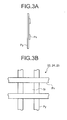
FIGS. 3 are configuration diagrams of a regulating plate in an introducing unit shown inFIG. 2 , whereFIG. 3A is a side view andFIG. 3B is a front view. -
FIG. 4 is an enlarged view around a bare tube part of a fin tube part shown inFIG. 2 . - An overall configuration of a thermal power plant that utilizes a heat exchanger according to an embodiment of the present invention is explained with reference to
FIG. 1 .
Coal and petroleum are used as the fuel for a boiler 1, and air pollutants such as nitrogen oxides (NOX), sulfur oxides (SOX), and dust are contained in flue gas from the boiler 1. - As shown in
FIG. 1 , the flue gas discharged from the boiler 1 is introduced into adenitrification system 2 having a catalyst filled therein.
In thedenitrification system 2, NOX in the flue gas is reduced to water and nitrogen by ammonium (NH3) charged as a reducing agent so as to become harmless.
High temperature flue gas discharged from thedenitrification system 2 passes through an air heater (A/H), and the temperature of the flue gas is generally 120 to 150°C. - This high temperature flue gas is introduced into a
heat recovery unit 3 serving as a heat exchanger, and heat exchange is performed with a heating medium (such as water), so that it is thermally recovered.
The temperature of the flue gas discharged from theheat recovery unit 3 is 80 to 110°C.
The heating medium heated by theheat recovery unit 3 is sent through a heating-medium circulating pipe 8 to areheater 6 to be described later.
A soot blower 9 is provided at a side of theheat recovery unit 3. - Low temperature flue gas discharged from the
heat recovery unit 3 is mixed and introduced into anelectronic precipitator 4, so that dust is removed from the low temperature flue gas.
Flue gas from which dust is removed is pressurized by an air blower (an ID fan) 10 that is driven by a motor.
There are cases that theair blower 10 is not provided. - The flue gas is then introduced into a
desulfurization system 5.
In thedesulfurization system 5, SOX in the flue gas is absorbed and removed by limestone and gypsum is produced as a by-product.
At this time, the temperature of the flue gas discharged from thedesulfurization system 5 is generally reduced to 45 to 55°C.
When this flue gas is discharged into air as it is, there are problems such that it is hardly diffused because of its low temperature and can become white smoke.
Therefore, the flue gas is introduced into thereheater 6. In thereheater 6, the flue gas is heated to a predetermined temperature or higher by a heating medium sent from theheat recovery unit 3 through the heating-medium circulating pipe 8 and the resultant gas is discharged from a stack 7. - While an example of the boiler 1 is shown in
FIG. 1 , various types of flue gas generators such as an internal combustion engine, a gas turbine, and an incinerator can be also used.
Furthermore, a thermal power generation plant and a refuse incineration plant can be used as the thermal power plant. - Details of the
heat recovery unit 3 serving as a heat exchanger are explained next with reference toFIG. 2 .
In addition to theheat recovery unit 3 shown inFIG. 2 , examples of the heat exchanger include a heat transfer tube, a reheater, a superheater, a heat exchanger tube, and a heat transfer tube.
As shown inFIG. 2 , the duct-shapedheat recovery unit 3 with a rectangular cross-section is connected to aflue gas duct 20 on a downstream side of thedenitrification system 2.
Flue gas discharged from thedenitrification system 2 shown inFIG. 1 is introduced into theheat recovery unit 3. - The
heat recovery unit 3 is constituted by an expandedpart 21 of a duct connected to a downstream side of theflue gas duct 20 and a heat-transfer tubebundle accommodating duct 22 connected to a downstream side of the expandedpart 21 of a duct. - A plurality of regulating
plates 23 to 27 are mounted either in the expandedpart 21 of a duct or the heat-transfer tubebundle accommodating duct 22 as explained below. - As shown in
FIG. 2 , three regulating plates (perforated plates) 23, 24, and 25 in an introducing unit are mounted on the expandedpart 21 of a duct.
One or all of the three regulating plates (perforated plates) 23, 24, and 25 in an introducing unit can be mounted on the heat-transfer tube bundle accommodating duct 22 (on an upstream side to a fin tube part 15).
As shown in a side view ofFIG. 3A and a front view ofFIG. 3B , each of the regulatingplates
In this case, openings of each of the regulatingplates plates - As a cross-sectional area of the
flue gas duct 20 is denoted by So, a total cross-sectional area of a large number of (a plurality of) openings of thefirst regulating plate 23 in an introducing unit is denoted by S1, a total cross-sectional area of a large number of (a plurality of) openings of thesecond regulating plate 24 in an introducing unit is denoted by S2, a total cross-sectional area of a large number of (a plurality of) openings of thethird regulating plate 25 in an introducing unit is denoted by S3, and a cross-sectional area of the heat-transfer tubebundle accommodating duct 22 is denoted by Sd, a large number of (a plurality of) openings are formed on therespective regulating plates - At least, the total cross-sectional area S3 of the openings of the third (the down-most stream side) regulating
plate 25 in an introducing unit is larger than the cross-sectional area So of theflue gas duct 20.
As described above, the regulatingplates - For example, the regulating plates are constituted so that the following condition is satisfied; that is, the cross-sectional area So < the total cross-sectional area S1 < the total cross-sectional area S2 < the total cross-sectional area S3 < the cross-sectional area Sd, the total cross-sectional area S1 < the cross-sectional area So < the total cross-sectional area S2 < the total cross-sectional area S3 < the cross-sectional area Sd, or the total cross-sectional area S1 < the total cross-sectional area S2 < the cross-sectional area So < the total cross-sectional area S3 < the cross-sectional area Sd.
- In this case, according to the plate formed by arranging flat plates in parallel crosses as shown in
FIGS. 3 , the number of the horizontal flat plates Px is equal to the number of the vertical flat plates Py and a distance between arranged horizontal flat plates Px or arranged vertical flat plates Py is equal or larger toward the regulatingplates
Alternatively, the number of the horizontal flat plates Px and the vertical flat plates Py can be increased toward the regulatingplates - Two or four or more (a plurality of) regulating plates in an introducing unit can be provided.
The shape of each of the regulatingplates FIGS. 3 , and a large number of circular openings can be formed on a flat plate.
The regulatingplate 25 in an introducing unit on the down-most stream side can be mounted on the heat-transfer tubebundle accommodating duct 22. - The regulating
plates first regulating plate 23 in an introducing unit in vertical and horizontal directions do not coincide with those of thesecond regulating plate 24 in an introducing unit in the vertical and horizontal directions, or the positions of the openings of thesecond regulating plate 24 in an introducing unit in the vertical and horizontal directions do not coincide with those of thethird regulating plate 25 in an introducing unit in the vertical and horizontal directions. With this configuration, the flow of the flue gas can be made more uniform.
According to the configuration shown inFIGS. 3 , for example, the position of a portion on the downstream side where the horizontal flat plate Px crosses the vertical flat plate Py in the vertical and horizontal directions is at the position of an opening Si on an upstream side in the vertical and horizontal directions. - Regulating plate in heat-transfer tube bundle accommodating duct
As shown inFIG. 2 , three (a plurality of) heat-transfer tube bundles, that is, a high-temperature heat-transfer tube bundle 11, a medium-temperature heat-transfer tube bundle 12, and a low-temperature heat-transfer tube bundle 13 are mounted on the heat-transfer tubebundle accommodating duct 22 of theheat recovery unit 3 in a flow direction of flue gas with a distance therebetween.
Each of the heat-transfer tube bundles 11 to 13 is constituted by the fin tube part (heat transfer unit) 15 of a plurality of columns and a large number of tiers and a bare tube part (U-shaped tube part) 18 that connects ends of adjacent ones of the fin tube parts (heat transfer units) 15.
An upstream end and a downstream end of each of the heat-transfer tube bundles 11 to 13 are respectively connected toheaders 14 mounted on a wall surface of theheat recovery unit 3. - The heating-
medium circulating pipe 8 shown inFIG. 1 is connected to each of theheaders 14.
Furthermore, a bare-tube-part upstream-side regulating plate 26 and a bare-tube-part downstream-side regulating plate 27 are respectively mounted on an upstream side and a downstream side of thebare tube part 18 at ends of each of thefin tube parts 15 so as to cover thebare tube part 18. - Detailed configurations of the bare-tube-part upstream-
side regulating plate 26 and the bare-tube-part downstream-side regulating plate 27 respectively mounted on the ends of thefin tube parts 15 are explained with reference toFIG. 4 .
Thefin tube part 15 is constituted by a plurality of straightheating medium tubes 16, a spiralheat transfer fin 17 mounted on an outer circumferential surface of each of theheating medium tubes 16, and thebare tube part 18 that connects ends of adjacentheating medium tubes 16. - The
heat transfer fin 17 is not mounted on thebare tube part 18 and thebare tube part 18 is accommodated in the heat-transfer tubebundle accommodating duct 22. Accordingly, there is a possibility that gas short-circuit pass occurs in thebare tube part 18.
To prevent gas short-circuit pass, the bare-tube-part upstream-side regulating plate 26 and the bare-tube-part downstream-side regulating plate 27 are mounted on a sidewall of the heat-transfer tubebundle accommodating duct 22 on an upstream side and a downstream side of thebare tube part 18, respectively. - A large number of holes with a diameter D are formed on the bare-tube-part upstream-
side regulating plate 26.
An aperture ratio due to the large number of holes is set to be 20 to 50%.
Theheating medium tube 16 is placed at a position where a length L between the heating medium tube 16 (an upstream end of the bare tube part 18) and the bare-tube-part upstream-side regulating plate 26 is ten or more times of the diameter D of a hole.
An upper limit of the ratio of the length L to the diameter D of a hole is inevitably determined by a length between adjacentfin tube parts 15 and a size of the heat-transfer tubebundle accommodating duct 22.
Meanwhile, a solid plate is placed as the bare-tube-part downstream-side regulating plate 27. - With this configuration, a pressure loss of a flue gas flow the
heating medium tube 16 can be made substantially equal to that at the part of thebare tube part 18. As a result, the flue gas can be regulated (drift can be reduced). - Both of the bare-tube-part upstream-
side regulating plate 26 and the bare-tube-part downstream-side regulating plate 27 can be solid. Alternatively, a large number of holes can be formed on the both plates.
Further, the bare-tube-part upstream-side regulating plate 26 and the bare-tube-part downstream-side regulating plate 27 can be made detachable in view of maintenance. - While respective embodiments of the present invention have been explained above, it is needless to mention that the present invention is not limited to the embodiments and various modifications can be made within the scope of the invention.
-
- 1
- boiler
- 2
- denitrification system
- 3
- heat recovery unit (heat exchanger)
- 4
- electronic precipitator
- 5
- desulfurization system
- 6
- reheater
- 7
- stack
- 8
- heating-medium circulating pipe
- 9
- soot blower
- 10
- air blower
- 11
- high-temperature heat-transfer tube bundle
- 12
- medium-temperature heat-transfer tube bundle
- 13
- low-temperature heat-transfer tube bundle
- 14
- header
- 15
- fin tube part (heat transfer unit)
- 16
- heating medium tube
- 17
- heat transfer fin
- 18
- bare tube part (U-shaped tube part)
- 20
- flue gas duct
- 21
- expanded part of duct
- 22
- heat-transfer tube bundle accommodating duct
- 23
- first regulating plate in introducing unit
- 24
- second regulating plate in introducing unit
- 25
- third regulating plate in introducing unit
- 26
- bare-tube-part upstream-side regulating plate
- 27
- bare-tube-part downstream-side regulating plate
- So
- cross-sectional area of flue gas duct
- S1
- total cross-sectional area of opening of first regulating plate in introducing unit
- S2
- total cross-sectional area of opening of second regulating plate in introducing unit
- S3
- total cross-sectional area of opening of third regulating plate in introducing unit
- Sd
- cross-sectional area of heat-transfer tube bundle accommodating duct
- Si
- respective openings of regulating plate in introducing unit
- D
- diameter of hole
- L
- length
- Px
- horizontal flat plate
- Py
- vertical flat plate
Claims (8)
- A heat exchanger including an expanded part of a duct (21), a heat-transfer tube bundle accommodating duct (22), and a plurality of heat-transfer tube bundles (11, 12, 13) provided in the heat-transfer tube bundle accommodating duct (22) in a flow direction of flue gas with a distance therebetween, the heat exchanger comprising:a bare-tube-part upstream-side regulating plate (26) and a bare-tube-part downstream-side regulating plate (27) respectively arranged on an upstream side and a downstream side of a bare tube part (18) of each of the heat-transfer tube bundles (11, 12, 13); anda plurality of regulating plates (23, 24, 15) in an introducing unit arranged either in the expanded part of a duct (21) or in the heat-transfer tube bundle accommodating duct (22) on an upstream side to the heat-transfer tube bundles (11, 12, 13).
- The heat exchanger according to claim 1, wherein the bare-tube-part upstream-side regulating plate (26) or the bare-tube-part downstream-side regulating plate (27) is a flat plate.
- The heat exchanger according to claim 1, wherein, the bare-tube-part upstream-side regulating plate (26) has a plurality of holes.
- The heat exchanger according to claim 3, wherein an aperture ratio of the plurality of holes of the bare-tube-part upstream-side regulating plate (26) is 20 to 50%.
- The heat exchanger according to claim 3 or 4, wherein a length between the bare-tube-part upstream-side regulating plate (26) and a heating medium tube (16) on an uppermost stream side of each of the heat-transfer tube bundles (11, 12, 13) is ten or more times of a diameter D of the holes.
- The heat exchanger according to claim 1, wherein a plurality of openings are formed on each of the regulating plates (23, 24, 25) in an introducing unit such that a pressure loss coefficient is set to be within 1 to 3.
- The heat exchanger according to claim 1, wherein the regulating plates (23, 24, 25) in an introducing unit are formed by arranging band-shaped flat plates in parallel crosses.
- The heat exchanger according to any of claims 1 to 7, wherein a plurality of openings on each of the regulating plates (23, 24, 25) in an introducing unit on a downstream side are formed such that a total area thereof is equal to or larger than a total area of a plurality of openings formed on the regulating plate in an introducing unit on an upstream side.
Applications Claiming Priority (2)
| Application Number | Priority Date | Filing Date | Title |
|---|---|---|---|
| JP2009065610A JP5010635B2 (en) | 2009-03-18 | 2009-03-18 | Heat exchanger |
| PCT/JP2009/063965 WO2010106699A1 (en) | 2009-03-18 | 2009-08-06 | Heat exchanger |
Publications (2)
| Publication Number | Publication Date |
|---|---|
| EP2410241A1 true EP2410241A1 (en) | 2012-01-25 |
| EP2410241A4 EP2410241A4 (en) | 2017-08-23 |
Family
ID=42739365
Family Applications (1)
| Application Number | Title | Priority Date | Filing Date |
|---|---|---|---|
| EP09841901.3A Withdrawn EP2410241A4 (en) | 2009-03-18 | 2009-08-06 | Heat exchanger |
Country Status (6)
| Country | Link |
|---|---|
| US (1) | US9400102B2 (en) |
| EP (1) | EP2410241A4 (en) |
| JP (1) | JP5010635B2 (en) |
| KR (1) | KR101277001B1 (en) |
| TW (1) | TW201035494A (en) |
| WO (1) | WO2010106699A1 (en) |
Families Citing this family (18)
| Publication number | Priority date | Publication date | Assignee | Title |
|---|---|---|---|---|
| JPH0610232B2 (en) | 1983-09-14 | 1994-02-09 | 住友化学工業株式会社 | Process for producing glycidyl ether of bromine-containing novolak type phenol resin |
| JPH0681779B2 (en) | 1989-07-17 | 1994-10-19 | 日本化薬株式会社 | Manufacturing method of high-purity flame-retardant epoxy resin |
| JP5721472B2 (en) * | 2011-02-28 | 2015-05-20 | 三菱重工業株式会社 | Heat exchanger |
| JP5705717B2 (en) * | 2011-12-16 | 2015-04-22 | 東京エレクトロン株式会社 | Heat exchanger for heat treatment apparatus and heat treatment apparatus provided with the same |
| TWI547674B (en) * | 2012-11-01 | 2016-09-01 | bao-ming Li | Heat supply system for heat supply systems |
| JP6296233B2 (en) * | 2014-03-13 | 2018-03-20 | 株式会社Ihi | Exhaust gas rectification structure, exhaust heat recovery boiler equipped with this rectification structure, and rectification method |
| JP6373058B2 (en) * | 2014-05-19 | 2018-08-15 | 株式会社サムソン | Tube group boiler |
| JP2017032232A (en) * | 2015-08-04 | 2017-02-09 | パナソニック株式会社 | Evaporator and Rankine cycle system |
| US10197272B2 (en) * | 2015-09-25 | 2019-02-05 | Fuel Tech, Inc. | Process and apparatus for reducing acid plume |
| EP3418666A4 (en) * | 2016-02-17 | 2019-11-06 | IHI Corporation | THERMAL TREATMENT APPARATUS |
| CN106090973B (en) * | 2016-06-22 | 2018-04-10 | 上海和衡能源科技发展有限公司 | Smoke processing system and method |
| JP2018109464A (en) * | 2016-12-28 | 2018-07-12 | 三菱重工業株式会社 | Heat exchanger and vessel |
| JP6718525B2 (en) * | 2017-01-30 | 2020-07-08 | 三菱日立パワーシステムズ株式会社 | Gas gas heat exchanger |
| KR101983969B1 (en) * | 2017-11-17 | 2019-09-03 | 한국전력공사 | Circulating fluid bed boiler |
| JP7130569B2 (en) * | 2019-02-01 | 2022-09-05 | 三菱重工業株式会社 | HEAT EXCHANGER, BOILER, AND METHOD FOR ADJUSTING HEAT EXCHANGER |
| CN110514052A (en) * | 2019-09-25 | 2019-11-29 | 江苏恒军动力科技有限公司 | A recuperator used in a micro gas turbine generator |
| IT201900022395A1 (en) * | 2019-11-28 | 2021-05-28 | Ac Boilers S P A | RECOVERY BOILER AND SYSTEM INCLUDING THIS RECOVERY BOILER |
| CN112696550B (en) * | 2020-12-28 | 2022-04-22 | 中国航空工业集团公司沈阳空气动力研究所 | Diffusion rectification flow equalization structure |
Family Cites Families (26)
| Publication number | Priority date | Publication date | Assignee | Title |
|---|---|---|---|---|
| US3191630A (en) * | 1963-04-11 | 1965-06-29 | Cottrell Res Inc | Gas flow control system for sub-sonic divergent diffusers |
| DE2439144C3 (en) * | 1974-08-14 | 1979-04-05 | Siemens Ag, 1000 Berlin Und 8000 Muenchen | Device for distributing flowing media from a flow cross-section to a different flow cross-section |
| US4285838A (en) * | 1977-12-08 | 1981-08-25 | Babcock-Hitachi Kabushiki Kaisha | Method of producing plate-shaped catalyst unit for NOx reduction of exhaust gas |
| DE2934137C2 (en) * | 1978-08-25 | 1985-05-15 | Nissan Motor Co., Ltd., Yokohama, Kanagawa | Flow measuring arrangement for measuring an amount of flow in a tubular channel |
| JPS5912671U (en) | 1982-07-15 | 1984-01-26 | 共同印刷株式会社 | Vertical three-fold envelope form |
| JPS6076708U (en) * | 1983-10-25 | 1985-05-29 | 三菱重工業株式会社 | fluid heating device |
| JPS60128107U (en) | 1984-02-01 | 1985-08-28 | 三菱重工業株式会社 | heat exchanger tube |
| US4685426A (en) * | 1986-05-05 | 1987-08-11 | The Babcock & Wilcox Company | Modular exhaust gas steam generator with common boiler casing |
| JPS6418101A (en) | 1987-07-13 | 1989-01-20 | Yasuto Ozaki | Prism for unidirectional diffusion |
| US5131459A (en) * | 1991-10-08 | 1992-07-21 | Deltak Corporation | Heat exchanger with movable tube assemblies |
| JPH066901U (en) * | 1992-06-17 | 1994-01-28 | 石川島播磨重工業株式会社 | Gas uneven flow prevention device for exhaust heat recovery boiler |
| US5256229A (en) | 1992-10-23 | 1993-10-26 | Denco, Inc. | Sterile containment welding device for plastic tubes |
| JP3426675B2 (en) * | 1993-12-24 | 2003-07-14 | 関西電力株式会社 | Rectifier |
| JPH0828808A (en) * | 1994-07-19 | 1996-02-02 | Babcock Hitachi Kk | Waste heat recovery boiler device and control method thereof |
| JPH08110007A (en) * | 1994-10-12 | 1996-04-30 | Ishikawajima Harima Heavy Ind Co Ltd | Loop tube wear prevention device for rear heat transfer section |
| JPH08145301A (en) * | 1994-11-25 | 1996-06-07 | Babcock Hitachi Kk | Waste heat recovery boiler |
| JPH08159402A (en) * | 1994-12-09 | 1996-06-21 | Babcock Hitachi Kk | Boiler device and heat transfer repair method |
| JPH09137906A (en) | 1995-11-14 | 1997-05-27 | Mitsubishi Heavy Ind Ltd | Exhaust heat recovery device |
| JP3572139B2 (en) | 1996-04-09 | 2004-09-29 | 三菱重工業株式会社 | Heat exchanger and flue gas treatment device provided with the same |
| JP3848750B2 (en) | 1997-08-29 | 2006-11-22 | 三菱重工業株式会社 | Horizontal heat exchanger |
| JPH11118101A (en) | 1997-10-20 | 1999-04-30 | Mitsubishi Heavy Ind Ltd | Horizontal heat exchanger in boiler |
| JP3546132B2 (en) | 1997-12-22 | 2004-07-21 | 三菱重工業株式会社 | Exhaust gas treatment method |
| DE19959342A1 (en) * | 1999-12-09 | 2001-06-13 | Abb Alstom Power Ch Ag | Heat recovery steam generator, especially for gas turbine unit of combined generation plant; has several parallel flow channels each assigned to section of catalyst unit to shut off individual channel |
| JP2006214625A (en) * | 2005-02-02 | 2006-08-17 | Babcock Hitachi Kk | Exhaust heat recovery boiler |
| JP4842007B2 (en) * | 2006-05-02 | 2011-12-21 | バブコック日立株式会社 | Waste heat recovery boiler |
| JP4854422B2 (en) * | 2006-07-31 | 2012-01-18 | バブコック日立株式会社 | Control method for once-through exhaust heat recovery boiler |
-
2009
- 2009-03-18 JP JP2009065610A patent/JP5010635B2/en not_active Expired - Fee Related
- 2009-08-06 KR KR1020117003860A patent/KR101277001B1/en not_active Expired - Fee Related
- 2009-08-06 WO PCT/JP2009/063965 patent/WO2010106699A1/en not_active Ceased
- 2009-08-06 EP EP09841901.3A patent/EP2410241A4/en not_active Withdrawn
- 2009-08-06 US US13/059,884 patent/US9400102B2/en not_active Expired - Fee Related
- 2009-09-30 TW TW098133291A patent/TW201035494A/en not_active IP Right Cessation
Non-Patent Citations (1)
| Title |
|---|
| See references of WO2010106699A1 * |
Also Published As
| Publication number | Publication date |
|---|---|
| KR20110043698A (en) | 2011-04-27 |
| JP2010216749A (en) | 2010-09-30 |
| EP2410241A4 (en) | 2017-08-23 |
| JP5010635B2 (en) | 2012-08-29 |
| KR101277001B1 (en) | 2013-06-24 |
| US9400102B2 (en) | 2016-07-26 |
| TWI372843B (en) | 2012-09-21 |
| TW201035494A (en) | 2010-10-01 |
| US20110139426A1 (en) | 2011-06-16 |
| WO2010106699A1 (en) | 2010-09-23 |
Similar Documents
| Publication | Publication Date | Title |
|---|---|---|
| US9400102B2 (en) | Heat exchanger including flow regulating plates | |
| US7021248B2 (en) | Passive system for optimal NOx reduction via selective catalytic reduction with variable boiler load | |
| EP2229572B1 (en) | Recuperator | |
| KR100309959B1 (en) | Array Recovery Boiler | |
| CN102562193B (en) | Thermal power plant | |
| US4912928A (en) | Exhaust heat exchanger system | |
| WO2016133116A1 (en) | Exhaust gas heat recovery system | |
| JP7221158B2 (en) | Heat exchanger, flue gas treatment device, and heat exchanger replacement method | |
| TWI757942B (en) | gas to gas heat exchanger | |
| EP3236025B1 (en) | System and method for improving the performance of a selective catalyst reduction system in a heat recovery steam generator | |
| KR101795039B1 (en) | Fin and tube heat exchanger | |
| EP3232022A1 (en) | System and method for improving the performance of a heat recovery steam generator | |
| JP2001272001A (en) | Boiler equipment | |
| US6405791B1 (en) | Air heater gas inlet plenum | |
| JP2005140370A (en) | Waste heat recovery boiler | |
| JP5144447B2 (en) | Boiler equipment | |
| KR102445936B1 (en) | Circulating Fluidized Bed Boiler | |
| CN112005073A (en) | heat exchanger | |
| CN222417372U (en) | Modularized waste heat boiler with SCR flue | |
| JP7766211B1 (en) | Bundle and heat exchanger, and flue gas treatment device | |
| JPS59153095A (en) | Heat exchanger | |
| KR101817018B1 (en) | Gas Gas Heater for desulfurization device | |
| JP2001090905A (en) | boiler | |
| JP6373058B2 (en) | Tube group boiler | |
| CN109282298A (en) | An integrated system for eliminating white smoke |
Legal Events
| Date | Code | Title | Description |
|---|---|---|---|
| PUAI | Public reference made under article 153(3) epc to a published international application that has entered the european phase |
Free format text: ORIGINAL CODE: 0009012 |
|
| 17P | Request for examination filed |
Effective date: 20110221 |
|
| AK | Designated contracting states |
Kind code of ref document: A1 Designated state(s): AT BE BG CH CY CZ DE DK EE ES FI FR GB GR HR HU IE IS IT LI LT LU LV MC MK MT NL NO PL PT RO SE SI SK SM TR |
|
| DAX | Request for extension of the european patent (deleted) | ||
| RAP1 | Party data changed (applicant data changed or rights of an application transferred) |
Owner name: MITSUBISHI HITACHI POWER SYSTEMS, LTD. |
|
| RAP1 | Party data changed (applicant data changed or rights of an application transferred) |
Owner name: MITSUBISHI HITACHI POWER SYSTEMS, LTD. |
|
| RA4 | Supplementary search report drawn up and despatched (corrected) |
Effective date: 20170721 |
|
| RIC1 | Information provided on ipc code assigned before grant |
Ipc: F23J 13/00 20060101ALI20170717BHEP Ipc: F22B 1/18 20060101ALI20170717BHEP Ipc: F22B 37/40 20060101AFI20170717BHEP |
|
| GRAP | Despatch of communication of intention to grant a patent |
Free format text: ORIGINAL CODE: EPIDOSNIGR1 |
|
| RIC1 | Information provided on ipc code assigned before grant |
Ipc: F23M 9/00 20060101ALI20180130BHEP Ipc: F22B 1/18 20060101ALI20180130BHEP Ipc: F22B 37/40 20060101AFI20180130BHEP |
|
| INTG | Intention to grant announced |
Effective date: 20180220 |
|
| STAA | Information on the status of an ep patent application or granted ep patent |
Free format text: STATUS: THE APPLICATION IS DEEMED TO BE WITHDRAWN |
|
| 18D | Application deemed to be withdrawn |
Effective date: 20180703 |