EP2410194A2 - Clutch Actuated By Initial Limit-Torque Sliding Damping - Google Patents
Clutch Actuated By Initial Limit-Torque Sliding Damping Download PDFInfo
- Publication number
- EP2410194A2 EP2410194A2 EP11175086A EP11175086A EP2410194A2 EP 2410194 A2 EP2410194 A2 EP 2410194A2 EP 11175086 A EP11175086 A EP 11175086A EP 11175086 A EP11175086 A EP 11175086A EP 2410194 A2 EP2410194 A2 EP 2410194A2
- Authority
- EP
- European Patent Office
- Prior art keywords
- clutch
- relay
- output
- limit
- axial
- Prior art date
- Legal status (The legal status is an assumption and is not a legal conclusion. Google has not performed a legal analysis and makes no representation as to the accuracy of the status listed.)
- Granted
Links
Images

Classifications
-
- F—MECHANICAL ENGINEERING; LIGHTING; HEATING; WEAPONS; BLASTING
- F16—ENGINEERING ELEMENTS AND UNITS; GENERAL MEASURES FOR PRODUCING AND MAINTAINING EFFECTIVE FUNCTIONING OF MACHINES OR INSTALLATIONS; THERMAL INSULATION IN GENERAL
- F16D—COUPLINGS FOR TRANSMITTING ROTATION; CLUTCHES; BRAKES
- F16D43/00—Automatic clutches
- F16D43/02—Automatic clutches actuated entirely mechanically
- F16D43/20—Automatic clutches actuated entirely mechanically controlled by torque, e.g. overload-release clutches, slip-clutches with means by which torque varies the clutching pressure
- F16D43/21—Automatic clutches actuated entirely mechanically controlled by torque, e.g. overload-release clutches, slip-clutches with means by which torque varies the clutching pressure with friction members
- F16D43/213—Automatic clutches actuated entirely mechanically controlled by torque, e.g. overload-release clutches, slip-clutches with means by which torque varies the clutching pressure with friction members with axially applied torque-limiting friction surfaces
- F16D43/218—Automatic clutches actuated entirely mechanically controlled by torque, e.g. overload-release clutches, slip-clutches with means by which torque varies the clutching pressure with friction members with axially applied torque-limiting friction surfaces with conical friction surfaces
-
- F—MECHANICAL ENGINEERING; LIGHTING; HEATING; WEAPONS; BLASTING
- F16—ENGINEERING ELEMENTS AND UNITS; GENERAL MEASURES FOR PRODUCING AND MAINTAINING EFFECTIVE FUNCTIONING OF MACHINES OR INSTALLATIONS; THERMAL INSULATION IN GENERAL
- F16D—COUPLINGS FOR TRANSMITTING ROTATION; CLUTCHES; BRAKES
- F16D41/00—Freewheels or freewheel clutches
- F16D41/04—Freewheels or freewheel clutches combined with a clutch for locking the driving and driven members
-
- F—MECHANICAL ENGINEERING; LIGHTING; HEATING; WEAPONS; BLASTING
- F16—ENGINEERING ELEMENTS AND UNITS; GENERAL MEASURES FOR PRODUCING AND MAINTAINING EFFECTIVE FUNCTIONING OF MACHINES OR INSTALLATIONS; THERMAL INSULATION IN GENERAL
- F16D—COUPLINGS FOR TRANSMITTING ROTATION; CLUTCHES; BRAKES
- F16D41/00—Freewheels or freewheel clutches
- F16D41/22—Freewheels or freewheel clutches with clutching ring or disc axially shifted as a result of lost motion between actuating members
Definitions
- a clutch actuated by initial limit-torque sliding damping is disclosed, characterized in that being capable of controlling a clutch device to perform operations of coupling or releasing with the driving torque, and being equipped with a relay transmission structure assembly (104) between a rotary prime motive end (101) and an output-end clutch structure (1052) installed at an output end (102), the relay transmission structure assembly (104) is installed with a relay coupling structure (204) having an active side of relay coupling structure and a passive side of relay coupling structure, the prime motive end (101) is provided with a limiting structure (115) for limiting relative positions of the relay transmission structure assembly (104) and the prime motive end (101); a limit-torque sliding damping device (106) is installed between the relay transmission structure assembly (104) and the output end (102) and is rotated in a first rotation direction at the prime motive end (101), so when the active side of relay coupling structure of the relay coupling structure (204) installed in the relay transmission structure assembly (104) is driven, a damping effect is generated by the limit-torque sliding damping
- a conventional single-way clutch (S.W.C.) or an over running clutch (O.R.C) has following transmission features:
- a clutch actuated by initial limit-torque sliding damping is disclosed, characterized in that being capable of controlling a clutch device to perform operations of coupling or releasing with the driving torque, and being equipped with a relay transmission structure assembly (104) between a rotary prime motive end (101) and an output-end clutch structure (1052) installed at an output end (102), the relay transmission structure assembly (104) is installed with a relay coupling structure (204) having an active side of relay coupling structure and a passive side of relay coupling structure, the prime motive end (101) is provided with a limiting structure (115) for limiting relative positions of the relay transmission structure assembly (104) and the prime motive end (101); a limit-torque sliding damping device (106) is installed between the relay transmission structure assembly (104) and the output end (102) and is rotated in a first rotation direction at the prime motive end (101), so when the active side of relay coupling structure of the relay coupling structure (204) installed in the relay transmission structure assembly (104) is driven, a damping effect is generated by the limit-torque sliding damping
- the present invention relates to a clutch actuated by initial limit-torque sliding damping is disclosed, characterized in that being capable of controlling a clutch device to perform operations of coupling or releasing with the driving torque, and being equipped with a relay transmission structure assembly (104) between a rotary prime motive end (101) and an output-end clutch structure (1052) installed at an output end (102), the relay transmission structure assembly (104) is installed with a relay coupling structure (204) having an active side of relay coupling structure and a passive side of relay coupling structure, the prime motive end (101) is provided with a limiting structure (115) for limiting relative positions of the relay transmission structure assembly (104) and the prime motive end (101); a limit-torque sliding damping device (106) is installed between the relay transmission structure assembly (104) and the output end (102) and is rotated in a first rotation direction at the prime motive end (101), so when the active side of relay coupling structure of the relay coupling structure (204) installed in the relay transmission structure assembly (104) is driven, a damping effect is generated by the limit
- FIG. 1 is a schematic view of the structural theory of the present invention
- FIG. 1 it mainly consists of:
- FIG. 10 is a cross sectional view of FIG. 9 .
- the initial limit-torque sliding damping structure between the output end (102) and the relay transmission structure assembly (104) is composed by one or more than one of following means:
- the clutch actuated by initial limit-torque sliding damping of the present invention can be composed by two sets of clutches actuated by initial limit-torque sliding damping and having the same prime motive end (101), including:
Landscapes
- Engineering & Computer Science (AREA)
- General Engineering & Computer Science (AREA)
- Mechanical Engineering (AREA)
- Mechanical Operated Clutches (AREA)
- One-Way And Automatic Clutches, And Combinations Of Different Clutches (AREA)
- Hydraulic Clutches, Magnetic Clutches, Fluid Clutches, And Fluid Joints (AREA)
Abstract
Description
- A clutch actuated by initial limit-torque sliding damping is disclosed, characterized in that being capable of controlling a clutch device to perform operations of coupling or releasing with the driving torque, and being equipped with a relay transmission structure assembly (104) between a rotary prime motive end (101) and an output-end clutch structure (1052) installed at an output end (102), the relay transmission structure assembly (104) is installed with a relay coupling structure (204) having an active side of relay coupling structure and a passive side of relay coupling structure, the prime motive end (101) is provided with a limiting structure (115) for limiting relative positions of the relay transmission structure assembly (104) and the prime motive end (101);
a limit-torque sliding damping device (106) is installed between the relay transmission structure assembly (104) and the output end (102) and is rotated in a first rotation direction at the prime motive end (101), so when the active side of relay coupling structure of the relay coupling structure (204) installed in the relay transmission structure assembly (104) is driven, a damping effect is generated by the limit-torque sliding damping device (106) installed between the relay transmission structure assembly (104) and the output end (102) such that the passive side of relay output coupling structure is driven by the active side of relay coupling structure to move, and the relay transmission structure assembly (104) and a relay output clutch structure (1051) installed in the relay transmission structure assembly (104) is driven to perform closing/opening operations with the output-end clutch structure (1052) installed at the output end (102) so as to transmit rotary kinetic energy, and a recovering actuation spring (120) provided between the relay output clutch structure (1051) and the output-end clutch structure (1052) is tightened;
when the rotational driving torque at the prime motive end (101) is no longer provided, the relay transmission structure assembly (104) is returned through actions of the recovering actuation spring (120), and the relay output clutch structure (1051) and the output-end clutch structure (1052) are in a released state, a limit-torque static coupling state is formed between the output end (102) and the relay transmission structure assembly (104) through the limit-torque sliding damping device (106). - A conventional single-way clutch (S.W.C.) or an over running clutch (O.R.C) has following transmission features:
- when an active side is driven in one rotational direction, e.g. the clockwise direction, a passive side is able to be linked; on the other hand, when the passive side is driven in the counterclockwise direction, the active side is able to be linked;
- when the active side is driven in the counterclockwise direction, the passive side is not able to be linked; when the passive side is driven in the clockwise direction, the active side is not able to be linked, the abovementioned are its transmission features;
- when the active side is desired to be driven in one of the directions, e.g. the clockwise direction, the passive side is able to be linked for rotational outputting, and when the passive side is driven in the counterclockwise direction, the active side is not able to be linked, which is not the function that the conventional single-way transmission device can provide.
- A clutch actuated by initial limit-torque sliding damping is disclosed, characterized in that being capable of controlling a clutch device to perform operations of coupling or releasing with the driving torque, and being equipped with a relay transmission structure assembly (104) between a rotary prime motive end (101) and an output-end clutch structure (1052) installed at an output end (102), the relay transmission structure assembly (104) is installed with a relay coupling structure (204) having an active side of relay coupling structure and a passive side of relay coupling structure, the prime motive end (101) is provided with a limiting structure (115) for limiting relative positions of the relay transmission structure assembly (104) and the prime motive end (101);
a limit-torque sliding damping device (106) is installed between the relay transmission structure assembly (104) and the output end (102) and is rotated in a first rotation direction at the prime motive end (101), so when the active side of relay coupling structure of the relay coupling structure (204) installed in the relay transmission structure assembly (104) is driven, a damping effect is generated by the limit-torque sliding damping device (106) installed between the relay transmission structure assembly (104) and the output end (102) such that the passive side of relay output coupling structure is driven by the active side of relay coupling structure to move, and the relay transmission structure assembly (104) and a relay output clutch structure (1051) installed in the relay transmission structure assembly (104) is driven to perform closing/opening operations with the output-end clutch structure (1052) installed at the output end (102) so as to transmit rotary kinetic energy, and a recovering actuation spring (120) provided between the relay output clutch structure (1051) and the output-end clutch structure (1052) is tightened;
when the rotational driving torque at the prime motive end (101) is no longer provided, the relay transmission structure assembly (104) is returned through actions of the recovering actuation spring (120), and the relay output clutch structure (1051) and the output-end clutch structure (1052) are in a released state, a limit-torque static coupling state is formed between the output end (102) and the relay transmission structure assembly (104) through the limit-torque sliding damping device (106);
the initial limit-torque sliding damping structure between the output end (102) and the relay transmission structure assembly (104) of the clutch actuated by initial limit-torque sliding damping of the present invention is composed by one or more than one of following means: - 1. when the output end (102) and the relay transmission structure assembly (104) are in the released state, a part of residual coupling torque is kept through the recovering actuation spring (120) or an axial clutch transmission block recovering spring (1073) or a radial clutch transmission block recovering spring (1083) so as to form the initial limit-torque sliding damping structure;
- 2. the coupling torque is generated through the limit-torque sliding damping device (106) installed between the output end (102) and the relay transmission structure assembly (104) so as to form the initial limit-torque sliding damping structure;
- 3. when the relay output clutch structure (1051) and the output-end clutch structure (1052) are in the released state, a part of residual coupling torque is kept so as to form the initial limit-torque sliding damping structure;
-
-
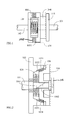
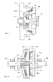
FIG. 1 is a schematic view of the structural theory of the clutch actuated by initial limit-torque sliding damping of the present invention. -
FIG. 2 is a schematic structural view of one embodiment illustrating that the relay coupling structure installed in the relay transmission structure assembly (104) is composed by the screw rod structure (1041) having axial actuation screw angle and the screw nut structure (1042) having axial actuation screw angle. -
FIG. 3 is a schematic structural view of one embodiment illustrating that the relay coupling structure installed in the relay transmission structure assembly (104) is composed by the coil-shaped spring capable of rotating for axial actuation (1043). -
FIG. 4 is a schematic structural view of one embodiment illustrating that the relay coupling structure installed in the relay transmission structure assembly (104) is composed by the axial compelling over running clutch. -
FIG. 5 is a structural schematic view of one embodiment illustrating that the relay coupling structure installed in the relay transmission structure assembly (104) is composed by the axial relay clutch of the axial clutch transmission block having axial compelling pre-forced recovering. -
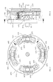
FIG. 6 is a cross sectional view ofFIG. 5 intersected along an A-A line. -
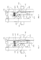
FIG. 7 is a schematic view illustrating the disengaged state of the axial clutch structure (1077) and the output-end clutch structure (1052) as shown inFIG. 5 . -
FIG. 8 is a schematic view illustrating the engaged state of the axial clutch structure (1077) and the output-end clutch structure (1052) as shown inFIG. 5 . -
FIG. 9 is a schematic structural view of one embodiment illustrating that the relay coupling structure and the relay outputting structure installed in the relay transmission structure assembly (104) is composed by the radial relay clutch of the radial clutch transmission block having radial compelling pre-forced recovering. -
FIG. 10 is a cross sectional view ofFIG. 9 . -
- 101: prime motive end
- 102: output end
- 104: relay transmission structure assembly
- 106: limit-torque sliding damping device
- 115: limiting structure
- 120: recovering actuation spring
- 204: relay coupling structure
- 1041: screw rod structure
- 1042: screw nut structure
- 1043: coil-shaped spring capable of rotating for axial actuation
- 1051: relay output clutch structure
- 1052: output-end clutch structure
- 1060: axial compelling over running clutch
- 1061: active side of axial compelling over running clutch
- 1062: passive side of axial compelling over running clutch
- 1063: middle rolling member
- 1071: active side of axial relay clutch
- 1072: axial clutch transmission block
- 1073: axial clutch transmission block recovering spring
- 1074: axial relay clutch transmission board
- 1075: middle rolling member
- 1076: passive side of axial relay clutch
- 1077: axial clutch structure
- 1079: transmission end
- 1081: active side of radial relay clutch
- 1082: radial clutch transmission block
- 1083: radial clutch transmission block recovering spring
- 1084: radial relay clutch transmission board
- 1085: middle rolling member
- 1086: passive side of radial relay clutch
- 1087: radial clutch structure
- 1089: transmission end
- The present invention relates to a clutch actuated by initial limit-torque sliding damping is disclosed, characterized in that being capable of controlling a clutch device to perform operations of coupling or releasing with the driving torque, and being equipped with a relay transmission structure assembly (104) between a rotary prime motive end (101) and an output-end clutch structure (1052) installed at an output end (102), the relay transmission structure assembly (104) is installed with a relay coupling structure (204) having an active side of relay coupling structure and a passive side of relay coupling structure, the prime motive end (101) is provided with a limiting structure (115) for limiting relative positions of the relay transmission structure assembly (104) and the prime motive end (101);
a limit-torque sliding damping device (106) is installed between the relay transmission structure assembly (104) and the output end (102) and is rotated in a first rotation direction at the prime motive end (101), so when the active side of relay coupling structure of the relay coupling structure (204) installed in the relay transmission structure assembly (104) is driven, a damping effect is generated by the limit-torque sliding damping device (106) installed between the relay transmission structure assembly (104) and the output end (102) such that the passive side of relay output coupling structure is driven by the active side of relay coupling structure to move, and the relay transmission structure assembly (104) and a relay output clutch structure (1051) installed in the relay transmission structure assembly (104) is driven to perform closing/opening operations with the output-end clutch structure (1052) installed at the output end (102) so as to transmit rotary kinetic energy, and a recovering actuation spring (120) provided between the relay output clutch structure (1051) and the output-end clutch structure (1052) is tightened;
when the rotational driving torque at the prime motive end (101) is no longer provided, the relay transmission structure assembly (104) is returned through actions of the recovering actuation spring (120), and the relay output clutch structure (1051) and the output-end clutch structure (1052) are in a released state, a limit-torque static coupling state is formed between the output end (102) and the relay transmission structure assembly (104) through the limit-torque sliding damping device (106);
the initial limit-torque sliding damping structure between the output end (102) and the relay transmission structure assembly (104) of the clutch actuated by initial limit-torque sliding damping of the present invention is composed by one or more than one of following means: - 1. when the output end (102) and the relay transmission structure assembly (104) are in the released state, a part of residual coupling torque is kept through the recovering actuation spring (120) or an axial clutch transmission block recovering spring (1073) or a radial clutch transmission block recovering spring (1083) so as to form the initial limit-torque sliding damping structure;
- 2. the coupling torque is generated through the limit-torque sliding damping device (106) installed between the output end (102) and the relay transmission structure assembly (104) so as to form the initial limit-torque sliding damping structure;
- 3. when the relay output clutch structure (1051) and the output-end clutch structure (1052) are in the released state, a part of residual coupling torque is kept so as to form the initial limit-torque sliding damping structure;
-
FIG. 1 is a schematic view of the structural theory of the present invention; - As shown in
FIG. 1 , it mainly consists of: - -- a prime motive end (101): composed by a rotational mechanism for inputting the rotary kinetic energy; the prime motive end (101) is served to drive an active side of relay coupling structure of a relay coupling structure (204) installed in a relay transmission structure assembly (104), the prime motive end (101) is installed with a limiting structure (115) for limiting relative positions of the relay transmission structure assembly (104) and the prime motive end (101);
- -- an output end (102): composed by a rotational mechanism for outputting the rotary kinetic energy; the output end (102) is connected to an output-end clutch structure (1052), and is controlled by the output-end clutch structure (1052);
- -- a relay transmission structure assembly (104): the relay transmission structure assembly (104) is installed between the prime motive end (101) and the output end (102), and is capable of performing rotational drive and axial movement, the relay transmission structure assembly (104) is provided with a relay coupling structure (204) driven by the prime motive end (101), the relay coupling structure (204) has an active side of relay coupling structure and a passive side of relay coupling structure coaxially coupled and interacted with the active side, a limit-torque sliding damping device (106) is installed between the mentioned transmission structure assembly (104) and the output end (102), when the active side of the relay coupling structure is driven by the prime motive end (101), so as to apply a rotational driving torque onto the passive side of relay coupling structure, a damping effect is generated by the limit-torque sliding damping device (106) installed between the relay transmission structure assembly (104) and the output end (102) such that the passive side of relay coupling structure is driven to move, and the relay transmission structure assembly (104) generates a relative movement, so as to drive the relay output clutch structure (1051) installed in the relay transmission structure assembly (104) to perform closing/opening operations with an output-end clutch structure (1052) for transmitting rotary kinetic energy, and a recovering actuation spring (120) is then forced being tightened; when the rotational driving torque from the prime motive end (101) to the output end (102) is no longer provided, the relay output clutch structure (1051) and the output-end clutch structure (1052) are in a released state through a release recovering effect provided by the recovering actuation spring (120) and the passive side of relay coupling structure is returned, and a limit-torque static coupling state is formed between the output end (102) and the relay transmission structure assembly (104) through the limit-torque sliding damping device (106);
- -- a limit-torque sliding damping device (106): composed by a mechanism device having limit-torque sliding damping effect with a restraining function while relative rotational movements are generated between the relay transmission structure assembly (104) and the output end (102); and is installed between the relay transmission structure assembly (104) and the output end (102), so through the limit-torque sliding damping device (106), relative movements are generated between the active side of relay coupling structure and the passive side of relay coupling structure combined in the relay transmission structure assembly (104) when the active side of relay coupling structure is driven by the prime motive end (101) to perform rotational drive;
the structure includes: constituted by the mechanism device, which is through the mechanical force, the spring pre-stressing force, the electromagnetic force of electric excited coil, or the action force of permanent magnet for the limit-torque sliding damping device (106) including between solid and solid, or between solid and viscous fluid, or between viscous fluid and viscous fluid, or between solid and gaseous or liquidity fluids to generate sliding damping; - -- a limiting structure (115): composed by a mechanism capable of limiting relative positions of the relay transmission structure assembly (104) and the prime motive end (101), and is combined with the rotary part of the prime motive end (101);
- -- a recovering actuation spring (120): which is a spring device capable of being pressed for storing energy and being released for outputting energy, and disposed between the relay output clutch structure (1051) and the output-end clutch structure (1052), and the normal state thereof is to allow the relay output clutch structure (1051) and the output-end clutch structure (1052) being in a released state, and a limit-torque static coupling state being formed between the output end (102) and the relay transmission structure assembly (104) through the limit-torque sliding damping device (106), and when the relay output clutch structure (1051) and the output-end clutch structure (1052) are driven so as to be engaged, the recovering actuation spring (120) is synchronously pre-pressed for being in an energy-storing state;
- --a relay output clutch structure (1051): the relay output clutch structure (1051) is installed in the relay transmission structure assembly (104), when the active side of relay coupling structure is driven by the prime motive end (101), the relay output clutch structure (1051) and the relay transmission structure assembly (104) are driven by the active side of relay coupling structure of the relay coupling structure (204), for performing closing/opening operations with the output-end clutch structure (1052) so as to transmit rotary kinetic energy, when the driving force from the prime motive end (101) to the output end (102) is no longer provided, the relay output clutch structure (1051) and the output-end clutch structure (1052) are in a released state through the releasing elastic force of the recovering actuation spring (120), and a limit-torque static coupling state is formed between the output end (102) and the relay transmission structure assembly (104) through the limit-torque sliding damping device (106);
- --an output-end clutch structure (1052): composed by a clutch function structure capable of performing closing/opening operations with the relay output clutch structure (1051) to transmit rotary kinetic energy, or being disengaged for terminating the transmission of the rotary kinetic energy, and the output-end clutch structure (1052) is connected to the output end (102);
- --the clutch structure of the relay output clutch structure (1051) and the output-end clutch structure (1052) consists of the friction-type clutch structure, the engaging-type clutch structure, or the synchro-engaging clutch structure;
In the clutch actuated by initial limit-torque sliding damping of present invention, the relay coupling structure (204) installed in the relay transmission structure assembly (104) can be further composed by a screw rod structure (1041) and a screw nut structure (1042);
FIG. 2 is a schematic structural view of one embodiment illustrating that the relay coupling structure installed in the relay transmission structure assembly (104) is composed by the screw rod structure (1041) having axial actuation screw angle and the screw nut structure (1042) having axial actuation screw angle.
As shown inFIG 2 , it mainly consists of: - -- a prime motive end (101): composed by a rotational mechanism for inputting the rotary kinetic energy; the prime motive end (101) is a screw rod structure (1041), having the function of active end of relay coupling structure, for driving the relay transmission structure assembly (104); the prime motive end (101) is installed with a limiting structure (115) for limiting relative positions of the relay transmission structure assembly (104) and the prime motive end (101);
- -- an output end (102): composed by a rotational mechanism for outputting the rotary kinetic energy; the output end (102) is connected to an output-end clutch structure (1052), and is controlled by the output-end clutch structure (1052);
- -- a relay transmission structure assembly (104): the relay transmission structure assembly (104) is installed between the prime motive end (101) and the output end (102), and is capable of performing rotational drive and axial movement, the relay transmission structure assembly (104) is installed with a relay coupling structure driven by the prime motive end (101), the relay coupling structure has the function of the active side of relay coupling structure composed by the screw rod structure (1041) and the function of passive side of relay coupling structure composed by the screw nut structure (1042), the screw rod structure (1041) and the screw nut structure (1042) are coaxially coupled and interacted, the above mentioned passive side of relay coupling structure composed by the screw nut structure (1042) is connected to the relay transmission structure assembly (104), a limit-torque sliding damping device (106) is installed between the relay transmission structure assembly (104) and the output end (102), when the screw rod structure (104 1) is driven by the prime motive end (10 1), so as to apply a rotational driving torque onto the screw nut structure (1042), through a damping effect generated by the limit-torque sliding damping device (106) installed between the relay transmission structure assembly (104) and the output end (102), the relay transmission structure assembly (104) connected with the screw nut structure (1042) generates a relative axial movement for driving the relay output clutch structure (1051) installed in the relay transmission structure assembly (104) to perform closing/opening operations with the output-end clutch structure (1052) for transmitting rotary kinetic energy, and the recovering actuation spring (120) is then forced being tightened;
when the rotational driving torque from the prime motive end (101) to the output end (102) is no longer provided, the relay output clutch structure (1051) and the output-end clutch structure (1052) are in a released state and the screw nut structure (1042) is returned through a recovering effect provided by the recovering actuation spring (120), and a limit-torque static coupling state is formed between the output end (102) and the relay transmission structure assembly (104) through the limit-torque sliding damping device (106); -- a limit-torque sliding damping device (106): composed by a mechanism device having limit-torque sliding damping effect with a restraining function while relative rotational movements are generated between the relay transmission structure assembly (104) and the output end (102); and is installed between the relay transmission structure assembly (104) and the output end (102); so when the screw rod structure (1041) is driven by the prime motive end (101) to perform rotational driving, through the limit-torque sliding damping device (106), relative movements are generated between the screw rod structure (1041) and the screw nut structure (1042) combined with the relay transmission structure assembly (104) during the screw rod structure (1041) performing rotational driving to the screw nut structure (1042) ;
the structure includes: constituted by the mechanism device, which is through the mechanical force, the spring pre-stressing force, the electromagnetic force of electric excited coil, or the action force of permanent magnet for the limit-torque sliding damping device (106) including between solid and solid, or between solid and viscous fluid, or between viscous fluid and viscous fluid, or between solid and gaseous or liquidity fluids to generate sliding damping; - -- a limiting structure (115): composed by a mechanism capable of limiting relative positions of the relay transmission structure assembly (104) and the prime motive end (101), and is combined with the rotary part of the prime motive end (101);
- --a recovering actuation spring (120): which is a spring device capable of being pressed for storing energy and being released for outputting energy, and disposed between the relay output clutch structure (1051) and the output-end clutch structure (1052), and the normal state thereof is to allow the relay output clutch structure (1051) and the output-end clutch structure (1052) being in a released state, and a limit-torque static coupling state being formed between the output end (102) and the relay transmission structure assembly (104) through the limit-torque sliding damping device (106), and when the relay output clutch structure (1051) and the output-end clutch structure (1052) are driven so as to be engaged, the recovering actuation spring (120) is synchronously pre-pressed for being in an energy-storing state;
- --a relay output clutch structure (1051): the relay output clutch structure (1051) is installed in the relay transmission structure assembly (104), when the screw rod structure (1041) is driven by the prime motive end (101), the relay output clutch structure (1051) and the relay transmission structure assembly (104) are driven by the screw rod structure (1041) of the relay coupling structure, for performing closing/opening operations with the output-end clutch structure (1052) so as to transmit rotary kinetic energy and to force to tighten the recovering actuation spring (120); when the rotational driving torque from the prime motive end (101) to the output end (102) is no longer provided, the relay output clutch structure (1051) and the output-end clutch structure (1052) are in a released state through the releasing elastic force of the recovering actuation spring (120), and a limit-torque static coupling state is formed between the output end (102) and the relay transmission structure assembly (104) through the limit-torque sliding damping device (106);
- --an out-put end clutch structure (1052): composed by a clutch function structure capable of performing closing/opening operations with the relay output clutch structure (1051) to transmit rotary kinetic energy, or being disengaged for terminating the transmission of the rotary kinetic energy, and the output-end clutch structure (1052) is connected to the output end (102);
- --the clutch structure of the relay output clutch structure (1051) and the output-end clutch structure (1052) consists of the friction-type clutch structure, the engaging-type clutch structure or the synchro-engaging clutch structure;
In the clutch actuated by initial limit-torque sliding damping of the present invention, the relay coupling structure installed in the relay transmission structure assembly (104) can be further composed by a coil-shaped spring capable of rotating for axial actuation (1043);
FIG. 3 is a schematic structural view of one embodiment illustrating that the relay coupling structure installed in the relay transmission structure assembly (104) is composed by the coil-shaped spring capable of rotating for axial actuation (1043).
As shown inFIG 3 , it main consists of: - -- a prime motive end (101): composed by a rotational mechanism for inputting rotary kinetic energy; the prime motive end (101) is a coil-shaped spring capable of rotating for axial actuation (1043) for driving the relay transmission structure assembly (104), the prime motive end (101) is installed with a limiting structure (115) for limiting relative positions of the relay transmission structure assembly (104) and the prime motive end (101);
- -- an output end (102): composed by a rotational mechanism for outputting rotary kinetic energy; the output end (102) is connected to an output-end clutch structure (1052), and is controlled by the output-end clutch structure (1052);
- -- a relay transmission structure assembly (104): the relay transmission structure assembly (104) is installed between the prime motive end (101) and the output end (102), and capable of rotational drive and axial movement, the relay transmission structure assembly (104) is installed with a coil-shaped spring capable of rotating for axial actuation (1043) serving to provide the relay coupling structure function and is coaxially shaft-installed between the relay transmission structure assembly (104) and the prime motive end (101), one end of the coil-shaped spring capable of rotating for axial actuation (1043) is fastened at the prime motive end (101) for providing the function of the active side of relay coupling structure, the other end of the coil-shaped spring capable of rotating for axial actuation (1043) is installed in the relay transmission structure assembly (104) for providing the function of the passive side of relay coupling structure, a limit-torque sliding damping device (106) is installed between the relay transmission structure assembly (104) and the output end (102); when the coil-shaped spring capable of rotating for axial actuation (1043) is processed with a tighten operation of angular displacement drive at the prime motive end (101), through a damping effect generated by the limit-torque sliding damping device (106) installed between the relay transmission structure assembly (104) and the output end (102), the coil-shaped spring capable of rotating for axial actuation (1043) generates an axial actuation force, so the relay transmission structure assembly (104) generates a relative axial movement, and further drives the relay output clutch structure (1051) installed in the relay transmission structure assembly (104) to perform closing/opening operations with the output-end clutch structure (1052) so as to transmit rotary kinetic energy, and force the recovering actuation spring (120) being tightened; when the rotational driving torque from the prime motive end (101) to the output end (102) is no longer provided, the relay output clutch structure (1051) and the output-end clutch structure (1052) are in a released state through the releasing recovering force of the recovering actuation spring (120) and the coil-shaped spring capable of rotating for axial actuation (1043) is returned, and a limit-torque static coupling state is formed between the output end (102) and the relay transmission structure assembly (104) through the limit-torque sliding damping device (106);
- -- a limit-torque sliding damping device (106): composed by a mechanism device having limit-torque sliding damping effect with a restraining function while relative rotational movements are generated between the relay transmission structure assembly (104) and the output end (102); and is installed between the relay transmission structure assembly (104) and the output end (102); when the coil-shaped spring capable of rotating for axial actuation (1043) is applied with an angular displacement driving force for tightening by the prime motive end (101), through the limit-torque sliding damping device (106), relative movements are generated in the relay transmission structure assembly (104);
the structure includes: constituted by the mechanism device, which is through the mechanical force, the spring pre-stressing force, the electromagnetic force of electric excited coil, or the action force of permanent magnet for the limit-torque sliding damping device (106) including between solid and solid, or between solid and viscous fluid, or between viscous fluid and viscous fluid, or between solid and gaseous or liquidity fluids to generate sliding damping; - -- a limiting structure (115): composed by a mechanism capable of limiting relative positions of the relay transmission structure assembly (104) and the prime motive end (101), and is combined with the rotary part of the prime motive end (101);
- --a recovering actuation spring (120): which is a spring device capable of being pressed for storing energy and being released for outputting energy, and disposed between the relay output clutch structure (1051) and the output-end clutch structure (1052), and the normal state thereof is to allow the relay output clutch structure (1051) and the output-end clutch structure (1052) being in a released state, and a limit-torque static coupling state being formed between the output end (102) and the relay transmission structure assembly (104) through the limit-torque sliding damping device (106), and when the relay output clutch structure (1051) and the output-end clutch structure (1052) are driven so as to be engaged, the recovering actuation spring (120) is synchronously pre-pressed for being in an energy-storing state;
- -- a relay output clutch structure (1051): the relay output clutch structure (1051) is installed in the relay transmission structure assembly (104), when the coil-shaped spring capable of rotating for axial actuation (1043) is driven at the prime motive end (101), the relay output clutch structure (1051) and the relay transmission structure assembly (104) are driven by the coil-shaped spring capable of rotating for axial actuation (1043) having the relay coupling structure function and installed between the relay transmission structure assembly (104) and the prime motive end (101), so as to perform closing/opening operations with the output-end clutch structure (1052) for transmitting rotary kinetic energy and forcing the recovering actuation spring (120) being tightened; when the rotational driving torque from the prime motive end (101) to the output end (102) is no longer provided, the relay output clutch structure (1051) and the output-end clutch structure (1052) are in a released state through the releasing recovering force of the recovering actuation spring (120) and the coil-shaped spring capable of rotating for axial actuation (1043) is returned, and a limit-torque static coupling state is formed between the output end (102) and the relay transmission structure assembly (104) through the limit-torque sliding damping device (106);
- --an out-put end clutch structure (1052): composed by a clutch function structure capable of performing closing/opening operations with the relay output clutch structure (1051) to transmit rotary kinetic energy, or being disengaged for terminating the transmission of the rotary kinetic energy, and the output-end clutch structure (1052) is connected to the output end (102);
- --the clutch structure of the relay output clutch structure (1051) and the output-end clutch structure (1052) consists of the friction-type clutch structure, the engaging-type clutch structure or the synchro-engaging clutch structure;
In the clutch actuated by initial limit-torque sliding damping of the present invention, the relay coupling structure (204) installed in the relay transmission structure assembly (104) can be further composed by an axial compelling over running clutch;
FIG. 4 is a schematic structural view of one embodiment illustrating that the relay coupling structure installed in the relay transmission structure assembly (104) is composed by the axial compelling over running clutch.
As shown inFIG. 4 , it mainly consists of: - -- a prime motive end (101): composed by a rotational mechanism for inputting the rotary kinetic energy; the prime motive end (101) is an active side of axial compelling over running clutch (1061), having the function of the active side of relay input coupling structure, for driving the relay transmission structure assembly (104), the prime motive end (101) is installed with a limiting structure (115) for limiting relative positions of the relay transmission structure assembly (104) and the prime motive end (101);
- -- an output end (102): composed by a rotational mechanism for outputting the rotary kinetic energy; the output end (102) is connected to an output-end clutch structure (1052), and is controlled by the output-end clutch structure (1052);
- -- a relay transmission structure assembly (104): the relay transmission structure assembly (104) is installed between the prime motive end (101) and the output end (102), the relay transmission structure assembly (104) is installed with an axial compelling over running clutch (1060) having the function of relay coupling structure, the axial compelling over running clutch (1060) has an active side of axial compelling over running clutch (1061) and a passive side of axial compelling over running clutch (1062) and middle rolling members (1063), a plurality of saw-shaped intervals are formed between the active side of axial compelling over running clutch (1061) and the passive side of axial compelling over running clutch (1062) for accommodating the middle rolling members (1063) so as to be equipped with the over running clutch function; a limit-torque sliding damping device (106) is installed between the relay transmission structure assembly (104) and the output end (102), when the axial compelling over running clutch (1060) is driven by the prime motive end (101), through a damping effect generated by the limit-torque sliding damping device (106) installed between the relay transmission structure assembly (104) and the output end (102), the active side of axial compelling over running clutch (1061) applies rotational driving torque to the passive side of axial compelling over running clutch (1062) via the middle running members (1063); before the middle rolling members (1063) are forced to be latched between the active side of axial compelling over running clutch (1061) and the passive side of axial compelling over running clutch (1062), the passive side of axial compelling over running clutch (1062) is compelled to be moved axially, so the relay transmission structure assembly (104) installed with the axial compelling over running clutch (1060) generates a relative movement for driving the relay output clutch structure (1051) installed in the relay transmission structure assembly (104) to perform opening/closing operations with the output-end clutch structure (1052) and forcing the recovering actuation spring (120) being tightened; when the rotational driving torque from the prime motive end (101) to the output end (102) is no longer provided, the relay output clutch structure (1051) and the output-end clutch structure (1052) are in a released state through the releasing recovering force of the recovering actuation spring (120) and the passive side of axial compelling over running clutch (1062) is returned, and a limit-torque static coupling state is formed between the output end (102) and the relay transmission structure assembly (104) through the limit-torque sliding damping device (106);
- -- a limit-torque sliding damping device (106): composed by a mechanism device having limit-torque sliding damping effect with a restraining function while relative rotational movements are generated between the relay transmission structure assembly (104) and the output end (102); and is installed between the relay transmission structure assembly (104) and the output end (102), when the active side of axial compelling over running clutch (1061) is driven by the prime motive end (101) to perform rotational driving, through the limit-torque sliding damping device (106), relative movements are generated between the active side of axial compelling over running clutch (1061) and the passive side of axial compelling over running clutch (1062);
the structure includes: constituted by the mechanism device, which is through the mechanical force, the spring pre-stressing force, the electromagnetic force of electric excited coil, or the action force of permanent magnet for the limit-torque sliding damping device (106) including between solid and solid, or between solid and viscous fluid, or between viscous fluid and viscous fluid, or between solid and gaseous or liquidity fluids to generate sliding damping; - -- a limiting structure (115): composed by a mechanism capable of limiting relative positions of the relay transmission structure assembly (104) and the prime motive end (101), and is combined with the rotary part of the prime motive end (101);
- --a recovering actuation spring (120): which is a spring device capable of being pressed for storing energy and being released for outputting energy, and disposed between the relay output clutch structure (1051) and the output-end clutch structure (1052), and the normal state thereof is to allow the relay output clutch structure (1051) and the output-end clutch structure (1052) being in a released state, and a limit-torque static coupling state being formed between the output end (102) and the relay transmission structure assembly (104) through the limit-torque sliding damping device (106), and when the relay output clutch structure (1051) and the output-end clutch structure (1052) are driven so as to be engaged, the recovering actuation spring (120) is synchronously pre-pressed for being in an energy-storing state;
- -- a relay output clutch structure (1051): the relay output clutch structure (1051) is installed in the relay transmission structure assembly (104), when the active side of axial compelling over running clutch (1061) is driven by the prime motive end (101), the passive side of axial compelling over running clutch (1062) installed in the relay transmission structure assembly (104) is axially driven so as to drive the relay transmission structure assembly (104) and the relay output clutch structure (1051) installed in the relay transmission structure assembly (104) for performing opening/closing operations with the output-end clutch structure (1052) for transmitting rotary kinetic energy and forcing the recovering actuation spring (120) being tightened; when the rotational driving torque from the prime motive end (101) to the output end (102) is no longer provided, the relay output clutch structure (1051) and the output-end clutch structure (1052) are in a released state through the releasing elastic force of the recovering actuation spring (120) and the passive side of axial compelling over running clutch (1062) is returned, and a limit-torque static coupling state is formed between the output end (102) and the relay transmission structure assembly (104) through the limit-torque sliding damping device (106);
- --an out-put end clutch structure (1052): composed by a clutch function structure capable of performing closing/opening operations with the relay output clutch structure (1051) to transmit rotary kinetic energy, or being disengaged for terminating the transmission of the rotary kinetic energy, and the output-end clutch structure (1052) is connected to the output end (102);
- --the clutch structure of the relay output clutch structure (1051) and the output-end clutch structure (1052) consists of the friction-type clutch structure, the engaging-type clutch structure or the synchro-engaging clutch structure;
In the clutch actuated by initial limit-torque sliding damping of the present invention, wherein the relay coupling structure installed in the relay transmission structure assembly (104) can be further composed by the axial relay clutch of the axial clutch transmission block having axial compelling pre-forces recovering.
FIG. 5 is a structural schematic view of one embodiment illustrating that the relay coupling structure installed in the relay transmission structure assembly (104) is composed by the axial relay clutch of the axial clutch transmission block having axial compelling pre-forced recovering.
As shown inFIG. 5 , it mainly consists of: - -- a prime motive end (101): composed by a rotational mechanism for inputting the rotary kinetic energy; the prime motive end (101) is an axial relay clutch, having the function of relay coupling structure, for driving the relay transmission structure assembly (104);
- -- an output end (102): composed by a rotational mechanism for outputting the rotary kinetic energy; the output end (102) is connected to an output-end clutch structure (1052), and is controlled by the output-end clutch structure (1052);
- -- a relay transmission structure assembly (104): the relay transmission structure assembly (104) is installed between the prime motive end (101) and the output end (102), the relay transmission structure assembly (104) is installed with an axial relay clutch which mainly consists of an active side of axial relay clutch (1071), an axial clutch transmission block (1072), an axial clutch transmission block recovering spring (1073), an axial relay clutch transmission board (1074), and a middle rolling member (1075); wherein the active side of axial relay clutch (1071) accommodating the middle rolling member (1075) is driven by the prime motive end (101), the middle rolling member (1075) is coupled to a passive side of axial relay clutch (1076) which is an obliquely compelled surface with respect to the axial clutch transmission block (1072), the axial clutch transmission block (1072) is installed on the axial relay clutch transmission board (1074), a limit-torque sliding damping device (106) is installed between the axial relay clutch transmission board (1074) and the output end (102), one end of the axial clutch transmission block (1072) is fastened on the axial relay clutch transmission board (1074), the other end of the axial clutch transmission block (1072) is served as a transmission end (1079), the passive side of axial relay clutch (1076) of the transmission end (1079) is an obliquely compelled surface allowing the middle rolling member (1075) to be coupled, the other surface of the transmission end (1079) is served as an axial clutch structure (1077), when the active side of axial relay clutch (1071) equipped with the middle rolling member (1075) is applied with rotational driving torque by the prime motive end (101), through a damping effect generated by the limit-torque sliding damping device (106) installed between the relay transmission structure assembly (104) and the output end (102), the passive side of the axial relay clutch (1076) which is an obliquely compelled surface with respect to the axial clutch transmission block (1072) is compelled to be moved by the middle rolling member (1075) installed at the active side of axial relay clutch (1071), and the axial clutch structure (1077) is moved to be coupled with the output-end clutch structure (1052) of the output end (102) for transmitting the rotary kinetic energy, when the rotational driving torque from the prime motive end (101) to the output end (102) is no longer provided, through the elasticity of the axial clutch transmission block (1072) and/or the releasing recovering force of the axial clutch transmission block recovering spring (1073) installed between the axial relay clutch transmission board (1074) and the middle rolling member (1075), such that the axial clutch structure (1077) of the axial clutch transmission block (1072) and the output-end clutch structure (1052) of the output end (102) are in a released state, and the axial relay clutch transmission board (1074) is returned, and a limit-torque static coupling state is formed between the output end (102) and the relay transmission structure assembly (104) through the limit-torque sliding damping device (106);
- -- a limit-torque sliding damping device (106): composed by a mechanism device having limit-torque sliding damping effect with a restraining function while relative rotational movements are generated between the axial relay clutch transmission board (1074) and the output end (102), and is installed between the output end (102) and the axial relay clutch transmission board (1074), when the active side of axial relay clutch (1071) is rotationally driven by the prime motive end (101), through actions of the limit-torque sliding damping device (106), the active side of axial relay clutch (1071) performs rotational driving to the axial relay clutch transmission board (1074), the axial clutch transmission block (1072) and the axial clutch structure (1077) installed at the axial relay clutch transmission board (1074) are compelled to move by the middle rolling member (1075) driven by the active side of axial relay clutch (1071), and thereby to generate relative movements;
the structure includes: constituted by the mechanism device, which is through the mechanical force, the spring pre-stressing force, the electromagnetic force of electric excited coil, or the action force of permanent magnet for the limit-torque sliding damping device (106) including between solid and solid, or between solid and viscous fluid, or between viscous fluid and viscous fluid, or between solid and gaseous or liquidity fluids to generate sliding damping; - -- an output-end clutch structure (1052): the output-end clutch structure (1052) is connected to the output end (102) and is served to perform opening/closing operations for transmitting rotary kinetic energy with the axial clutch structure (1077) of the transmission end (1079) of the axial clutch transmission block (1072) of the axial relay clutch transmission board (1074), or in a released state; a limit-torque static coupling state is formed between the output end (102) and the relay transmission structure assembly (104) through the limit-torque sliding damping device (106);
- -- the clutch structure of the axial clutch structure (1077) and the output-end clutch structure (1052) consists of the friction-type clutch structure, the engaging-type clutch structure or the synchro-engaging clutch structure;
- -- a middle rolling member (1075): which can be replaced by rolling balls, cone-shaped cylinders, or spherical or arc-shaped protrusions;
In the clutch actuated by initial limit-torque sliding damping of the present invention, the relay output coupling structure installed in the relay transmission structure assembly (104) can be further composed by a radial relay clutch of the radial clutch transmission block having radial compelling pre-forced recovering;
FIG. 6 is a cross sectional view ofFIG 5 intersected along an A-A line.
FIG. 7 is a schematic view illustrating the disengaged state of the axial clutch structure (1077) and the output-end clutch structure (1052) as shown inFIG. 5 .
FIG. 8 is a schematic view illustrating the engaged state of the axial clutch structure (1077) and the output-end clutch structure (1052) as shown inFIG. 5 .
FIG. 9 is a schematic structural view of one embodiment illustrating that the relay coupling structure and the relay outputting structure installed in the relay transmission structure assembly (104) is composed by the radial relay clutch of the radial clutch transmission block having radial compelling pre-forced recovering.
As shown inFIG. 9 , it mainly consists of: - -- a prime motive end (101): composed by a rotational mechanism for inputting the rotary kinetic energy; the prime motive end (101) is a radial relay clutch, having the function of relay coupling structure, for driving the relay transmission structure assembly (104);
- -- an output end (102): composed by a rotational mechanism for outputting the rotary kinetic energy; the annular interior of the output end (102) is installed with an output-end clutch structure (1052), and is controlled by the output-end clutch structure (1052);
- -- a relay transmission structure assembly (104): the relay transmission structure assembly (104) is installed between the prime motive end (101) and the output end (102), the three components are arranged as a concentric annular structure, the relay transmission structure assembly (104) has a radial relay clutch which mainly consists of an active side of radial relay clutch (1081), a radial clutch transmission block (1082), a radial clutch transmission block recovering spring (1083), a radial relay clutch transmission board (1084), and a middle rolling member (1085); wherein the active side of radial relay clutch (1081) accommodating the middle rolling member (1085) is driven by the prime motive end (101), the middle rolling member (1085) is coupled to a passive side of radial relay clutch (1086) which is an obliquely compelled surface with respect to the radial clutch transmission block (1082), the radial clutch transmission block (1082) is installed on the radial relay clutch transmission board (1084), a limit-torque sliding damping device (106) is installed between the radial relay clutch transmission board (1084) and the output end (102), one end of the radial clutch transmission block (1082) is fastened on the radial relay clutch transmission board (1084), the other end of the radial clutch transmission block (1082) is served as a transmission end (1089), the passive side of radial relay clutch (1086) of the transmission end (1089) is an obliquely compelled surface allowing the middle rolling member (1085) to be coupled, the other surface of the transmission end (1089) is served as a radial clutch structure (1087), when the active side of the radial relay clutch (1081) equipped with the middle rolling member (1085) is applied with rotational driving torque by the prime motive end (101), through a damping effect generated by the limit-torque sliding damping device (106) installed between the relay transmission structure assembly (104) and the output end (102), the passive side of radial relay clutch (1086) which is an obliquely compelled surface with respect to the radial clutch transmission block (1082) is compelled to be moved by the middle rolling member (1085) installed at the active side of radial relay clutch (1081), and the radial clutch structure (1087) is moved to be coupled with the output-end clutch structure (1052) of the output end (102) for transmitting the rotary kinetic energy, when the rotational driving torque from the prime motive end (101) to the output end (102) is no longer provided, through the elasticity of the radial clutch transmission block (1082) and/or the releasing recovering force of the radial clutch transmission block recovering spring (1083) installed between the radial relay clutch transmission board (1084) and the middle rolling member (1085), such that the radial clutch structure (1087) of the radial clutch transmission block (1082) and the output-end clutch structure (1052) of the output end (102) are in a released state, and the radial relay clutch transmission board (1084) is returned, and a limit-torque static coupling state is formed between the output end (102) and the relay transmission structure assembly (104) through the limit-torque sliding damping device (106);
- -- a limit-torque sliding damping device (106): composed by a mechanism device having limit-torque sliding damping effect with a restraining function while relative rotational movements are generated between the radial relay clutch transmission board (1084) and the output end (102), and is installed between the output end (102) and the radial relay clutch transmission board (1084), when the active side of radial relay clutch (1081) is rotationally driven by the prime motive end (101), through actions of the limit-torque sliding damping device (106), the active side of radial relay clutch (1081) performs rotational driving to the radial relay clutch transmission board (1084), the radial clutch transmission block (1082) and the radial clutch structure (1087) installed at the radial relay clutch transmission board (1084) are compelled to move by the middle rolling member (1085) driven by the active side of radial relay clutch (1081), and thereby to generate relative movements;
the structure includes: constituted by the mechanism device, which is through the mechanical force, the spring pre-stressing force, the electromagnetic force of electric excited coil, or the action force of permanent magnet for the limit-torque sliding damping device (106) including between solid and solid, or between solid and viscous fluid, or between viscous fluid and viscous fluid, or between solid and gaseous or liquidity fluids to generate sliding damping; - -- an output-end clutch structure (1052): the output-end clutch structure (1052) is connected to the output end (102) and is served to perform opening/closing operations for transmitting rotary kinetic energy with the radial clutch structure (1087) of the transmission end (1089) of the radial clutch transmission block (1082) of the radial relay clutch transmission board (1084), or in a released state; a limit-torque static coupling state is formed between the output end (102) and the relay transmission structure assembly (104) through the limit-torque sliding damping device (106);
- -- the clutch structure of the radial clutch structure (1087) and the output-end clutch structure (1052) consists of the friction-type clutch structure, the engaging-type clutch structure or the synchro-engaging clutch structure;
- -- a middle rolling member (1085): which can be replaced by rolling balls, cone-shaped cylinders, or spherical or arc-shaped protrusions;
-
FIG. 10 is a cross sectional view ofFIG. 9 . - In the clutch actuated by initial limit-torque sliding damping of the present invention, the initial limit-torque sliding damping structure between the output end (102) and the relay transmission structure assembly (104) is composed by one or more than one of following means:
- 1. when the output end (102) and the relay transmission structure assembly (104) are in the released state, a part of residual coupling torque is kept through the recovering actuation spring (120) or the axial clutch transmission block recovering spring (1073) or the radial clutch transmission block recovering spring (1083) so as to form the initial limit-torque sliding damping structure;
- 2. coupling torque is generated through the limit-torque sliding damping device (106) installed between the output end (102) and the relay transmission structure assembly (104) so as to form the initial limit-torque sliding damping structure;
- 3. when the relay output clutch structure (1051) and the output-end clutch structure (1052) are in the released state, a part of residual coupling torque is kept so as to form the initial limit-torque sliding damping structure;
- In the clutch actuated by initial limit-torque sliding damping of the present invention, it can be composed by two sets of clutches actuated by initial limit-torque sliding damping and having the same prime motive end (101), including:
- 1. two sets of clutches actuated by initial limit-torque sliding damping both transmitting in the axial direction, having different operation directions and having the same prime motive end (101);
- 2. two sets of clutches actuated by initial limit-torque sliding damping both transmitting in the axial direction, having the same operation direction and having the same prime motive end (101);
- 3. two sets of clutches actuated by initial limit-torque sliding damping both transmitting in the radial direction, having different operation directions and having the same prime motive end (101);
- 4. two sets of clutches actuated by initial limit-torque sliding damping both transmitting in the radial direction, having the same operation direction and having the same prime motive end (101);
- 5. two sets of clutches actuated by initial limit-torque sliding damping in which one set transmitting in the radial direction and the other transmitting in the axial direction, having different operation directions and having the same prime motive end (101);
- 6. two sets of clutches actuated by initial limit-torque sliding damping in which one set transmitting in the radial direction and the other transmitting in the axial direction, having the same operation direction and having the same prime motive end (101).
- According to one aspect of the present invention, a clutch actuated by initial limit-torque sliding damping capable of controlling a clutch device to perform operations of coupling or releasing with the drive torque comprises a relay transmission structure assembly (104) installed between a rotary prime motive end (101) and an output end clutch structure (1052), the relay transmission structure assembly (104) being installed with a relay coupling structure (204) having an active side and a passive side, and a limit torque sliding damping device (106) installed between the relay transmission structure assembly (104) and the output end (102).
Claims (14)
- A clutch actuated by initial limit-torque sliding damping, characterized in that being capable of controlling a clutch device to perform operations of coupling or releasing with the driving torque, and a relay transmission structure assembly (104) between a rotary prime motive end (101) and an output-end clutch structure (1052) is installed at an output end (102), the relay transmission structure assembly (104) is installed with a relay coupling structure (204) having an active side of relay coupling structure and a passive side of relay coupling structure, the prime motive end (101) is provided with a limiting structure (115) for limiting relative positions of the relay transmission structure assembly (104) and the prime motive end (101);
a limit-torque sliding damping device (106) is installed between the relay transmission structure assembly (104) and the output end (102) and is rotated in a first rotation direction at the prime motive end (101), so when the active side of relay coupling structure of the relay coupling structure (204) installed in the relay transmission structure assembly (104) is driven, a damping effect is generated by the limit-torque sliding damping device (106) installed between the relay transmission structure assembly (104) and the output end (102) such that the passive side of relay output coupling structure is driven by the active side of relay coupling structure to move, and the relay transmission structure assembly (104) and a relay output clutch structure (1051) installed in the relay transmission structure assembly (104) is driven to perform closing/opening operations with the output-end clutch structure (1052) installed at the output end (102) so as to transmit the rotary kinetic energy, and a recovering actuation spring (120) provided between the relay output clutch structure (1051) and the output-end clutch structure (1052) is tightened;
when the rotational driving torque at the prime motive end (101) is no longer provided, the relay transmission structure assembly (104) is returned through actions of the recovering actuation spring (120), and the relay output clutch structure (1051) and the output-end clutch structure (1052) are in a released state, a limit-torque static coupling state is formed between the output end (102) and the relay transmission structure assembly (104) through the limit-torque sliding damping device (106);
the initial limit-torque sliding damping structure between the output end (102) and the relay transmission structure assembly (104) of the clutch actuated by initial limit-torque sliding damping is composed by one or more than one of following means:1. when the output end (102) and the relay transmission structure assembly (104) are in the released state, a part of residual coupling torque is kept through the recovering actuation spring (120) or an axial clutch transmission block recovering spring (1073) or a radial clutch transmission block recovering spring (1083) so as to form the initial limit-torque sliding damping structure;2. the coupling torque is generated through the limit-torque sliding damping device (106) installed between the output end (102) and the relay transmission structure assembly (104) so as to form the initial limit-torque sliding damping structure;3. when the relay output clutch structure (1051) and the output-end clutch structure (1052) are in the released state, a part of residual coupling torque is kept so as to form the initial limit-torque sliding damping structure. - The clutch actuated by initial limit-torque sliding damping as claimed in claim 1, wherein it mainly consists of:-- a prime motive end (101): composed by a rotational mechanism for inputting the rotary kinetic energy; the prime motive end (101) is served to drive an active side of relay coupling structure of a relay coupling structure (204) installed in a relay transmission structure assembly (104), the prime motive end (101) is installed with a limiting structure (115) for limiting relative positions of the relay transmission structure assembly (104) and the prime motive end (101);-- an output end (102): composed by a rotational mechanism for outputting the rotary kinetic energy; the output end (102) is connected to an output-end clutch structure (1052), and is controlled by the output-end clutch structure (1052);-- a relay transmission structure assembly (104): the relay transmission structure assembly (104) is installed between the prime motive end (101) and the output end (102), and is capable of performing rotational drive and axial movement, the relay transmission structure assembly (104) is provided with a relay coupling structure (204) driven by the prime motive end (101), the relay coupling structure (204) has an active side of relay coupling structure and a passive side of relay coupling structure coaxially coupled and interacted with the active side, a limit-torque sliding damping device (106) is installed between the mentioned transmission structure assembly (104) and the output end (102), when the active side of the relay coupling structure is driven by the prime motive end (101), so as to apply a rotational driving torque onto the passive side of relay coupling structure, a damping effect is generated by the limit-torque sliding damping device (106) installed between the relay transmission structure assembly (104) and the output end (102) such that the passive side of relay coupling structure is driven to move, and the relay transmission structure assembly (104) generates a relative movement, so as to drive the relay output clutch structure (1051) installed in the relay transmission structure assembly (104) to perform closing/opening operations with an output-end clutch structure (1052) for transmitting rotary kinetic energy, and a recovering actuation spring (120) is then forced being tightened; when the rotational driving torque from the prime motive end (101) to the output end (102) is no longer provided, the relay output clutch structure (1051) and the output-end clutch structure (1052) are in a released state through a release recovering effect provided by the recovering actuation spring (120) and the passive side of relay coupling structure is returned, and a limit-torque static coupling state is formed between the output end (102) and the relay transmission structure assembly (104) through the limit-torque sliding damping device (106);-- a limit-torque sliding damping device (106): composed by a mechanism device having limit-torque sliding damping effect with a restraining function while relative rotational movements are generated between the relay transmission structure assembly (104) and the output end (102); and is installed between the relay transmission structure assembly (104) and the output end (102), so through the limit-torque sliding damping device (106), relative movements are generated between the active side of relay coupling structure and the passive side of relay coupling structure combined in the relay transmission structure assembly (104) when the active side of relay coupling structure is driven by the prime motive end (101) to perform rotational drive;
the structure includes: constituted by the mechanism device, which is through the mechanical force, the spring pre-stressing force, the electromagnetic force of electric excited coil, or the action force of permanent magnet for the limit-torque sliding damping device (106) including between solid and solid, or between solid and viscous fluid, or between viscous fluid and viscous fluid, or between solid and gaseous or liquidity fluids to generate sliding damping;-- a limiting structure (115): composed by a mechanism capable of limiting relative positions of the relay transmission structure assembly (104) and the prime motive end (101), and is combined with the rotary part of the prime motive end (101);-- a recovering actuation spring (120): which is a spring device capable of being pressed for storing energy and being released for outputting energy, and disposed between the relay output clutch structure (1051) and the output-end clutch structure (1052), and the normal state thereof is to allow the relay output clutch structure (1051) and the output-end clutch structure (1052) being in a released state, and a limit-torque static coupling state being formed between the output end (102) and the relay transmission structure assembly (104) through the limit-torque sliding damping device (106), when the relay output clutch structure (1051) and the output-end clutch structure (1052) are driven so as to be engaged, the recovering actuation spring (120) is synchronously pre-pressed for being in an energy-storing state;--a relay output clutch structure (1051): the relay output clutch structure (1051) is installed in the relay transmission structure assembly (104), when the active side of relay coupling structure is driven by the prime motive end (101), the relay output clutch structure (1051) and the relay transmission structure assembly (104) are driven by the active side of relay coupling structure of the relay coupling structure (204), for performing closing/opening operations with the output-end clutch structure (1052) so as to transmit rotary kinetic energy, when the driving force from the prime motive end (101) to the output end (102) is no longer provided, the relay output clutch structure (1051) and the output-end clutch structure (1052) are in a released state through the releasing elastic force of the recovering actuation spring (120), and a limit-torque static coupling state is formed between the output end (102) and the relay transmission structure assembly (104) through the limit-torque sliding damping device (106);--an output-end clutch structure (1052): composed by a clutch function structure capable of performing closing/opening operations with the relay output clutch structure (1051) to transmit rotary kinetic energy, or being disengaged for terminating the transmission of the rotary kinetic energy, and the output-end clutch structure (1052) is connected to the output end (102);--the clutch structure of the relay output clutch structure (1051) and the output-end clutch structure (1052) consists of the friction-type clutch structure, the engaging-type clutch structure or the synchro-engaging clutch structure. - The clutch actuated by initial limit-torque sliding damping as claimed in claim 1 or 2, wherein the relay coupling structure installed in the relay transmission structure assembly (104) is further composed by a screw rod structure (1041) and a screw nut structure (1042), wherein it mainly consists of:-- a prime motive end (101): composed by a rotational mechanism for inputting the rotary kinetic energy; the prime motive end (101) is a screw rod structure (1041), having the function of active end of relay coupling structure, for driving the relay transmission structure assembly (104); the prime motive end (101) is installed with a limiting structure (115) for limiting relative positions of the relay transmission structure assembly (104) and the prime motive end (101);-- an output end (102): composed by a rotational mechanism for outputting the rotary kinetic energy; the output end (102) is connected to an output-end clutch structure (1052), and is controlled by the output-end clutch structure (1052);-- a relay transmission structure assembly (104): the relay transmission structure assembly (104) is installed between the prime motive end (101) and the output end (102), and is capable of performing rotational drive and axial movement, the relay transmission structure assembly (104) is installed with a relay coupling structure driven by the prime motive end (101), the relay coupling structure has the function of active side of relay coupling structure composed by the screw rod structure (1041) and the function of passive side of relay coupling structure composed by the screw nut structure (1042), the screw rod structure (1041) and the screw nut structure (1042) are coaxially coupled and interacted, the above mentioned passive side of relay coupling structure composed by the screw nut structure (1042) is connected to the relay transmission structure assembly (104), a limit-torque sliding damping device (106) is installed between the relay transmission structure assembly (104) and the output end (102), when the screw rod structure (1041) is driven by the prime motive end (101), so as to apply a rotational driving torque onto the screw nut structure (1042), through a damping effect generated by the limit-torque sliding damping device (106) installed between the relay transmission structure assembly (104) and the output end (102), the relay transmission structure assembly (104) connected with the screw nut structure (1042) generates a relative axial movement for driving the relay output clutch structure (1051) installed in the relay transmission structure assembly (104) to perform closing/opening operations with the output-end clutch structure (1052) for transmitting rotary kinetic energy, and the recovering actuation spring (120) is then forced being tightened;
when the rotational driving torque from the prime motive end (101) to the output end (102) is no longer provided, the relay output clutch structure (1051) and the output-end clutch structure (1052) are in a released state and the screw nut structure (1042) is returned through a recovering effect provided by the recovering actuation spring (120), and a limit-torque static coupling state is formed between the output end (102) and the relay transmission structure assembly (104) through the limit-torque sliding damping device (106);-- a limit-torque sliding damping device (106): composed by a mechanism device having limit-torque sliding damping effect with a restraining function while relative rotational movements are generated between the relay transmission structure assembly (104) and the output end (102); and is installed between the relay transmission structure assembly (104) and the output end (102); so when the screw rod structure (1041) is driven by the prime motive end (101) to perform rotational driving, through the limit-torque sliding damping device (106), relative movements are generated between the screw rod structure (1041) and the screw nut structure (1042) combined in the relay transmission structure assembly (104) during the screw rod structure (1041) performing rotational driving to the screw nut structure (1042);
the structure includes: constituted by the mechanism device, which is through the mechanical force, the spring pre-stressing force, the electromagnetic force of electric excited coil, or the action force of permanent magnet for the limit-torque sliding damping device (106) including between solid and solid, or between solid and viscous fluid, or between viscous fluid and viscous fluid, or between solid and gaseous or liquidity fluids to generate sliding damping;-- a limiting structure (115): composed by a mechanism capable of limiting relative positions of the relay transmission structure assembly (104) and the prime motive end (101), and is combined with the rotary part of the prime motive end (101);--a recovering actuation spring (120): which is a spring device capable of being pressed for storing energy and being released for outputting energy, and disposed between the relay output clutch structure (1051) and the output-end clutch structure (1052), and the normal state thereof is to allow the relay output clutch structure (1051) and the output-end clutch structure (1052) being in a released state, and a limit-torque static coupling state being formed between the output end (102) and the relay transmission structure assembly (104) through the limit-torque sliding damping device (106), and when the relay output clutch structure (1051) and the output-end clutch structure (1052) are driven so as to be engaged, the recovering actuation spring (120) is synchronously pre-pressed for being in an energy-storing state;--a relay output clutch structure (1051): the relay output clutch structure (1051) is installed in the relay transmission structure assembly (104), when the screw rod structure (1041) is driven by the prime motive end (101), the relay output clutch structure (1051) and the relay transmission structure assembly (104) are driven by the screw rod structure (1041) of the relay coupling structure, for performing closing/opening operations with the output-end clutch structure (1052) so as to transmit rotary kinetic energy and to force to tighten the recovering actuation spring (120); when the rotational driving torque from the prime motive end (101) to the output end (102) is no longer provided, the relay output clutch structure (1051) and the output-end clutch structure (1052) are in a released state through the releasing elastic force of the recovering actuation spring (120), and a limit-torque static coupling state is formed between the output end (102) and the relay transmission structure assembly (104) through the limit-torque sliding damping device (106);--an out-put end clutch structure (1052): composed by a clutch function structure capable of performing closing/opening operations with the relay output clutch structure (1051) to transmit rotary kinetic energy, or being disengaged for terminating the transmission of the rotary kinetic energy, and the output-end clutch structure (1052) is connected to the output end (102);--the clutch structure of the relay output clutch structure (1051) and the output-end clutch structure (1052) consists of the friction-type clutch structure, the engaging-type clutch structure or the synchro-engaging clutch structure. - The clutch actuated by initial limit-torque sliding damping as claimed in any one of the preceding claims, wherein the relay coupling structure installed in the relay transmission structure assembly (104) is further composed by a coil-shaped spring capable of rotating for axial actuation (1043), wherein it mainly consists of:-- a prime motive end (101): composed by a rotational mechanism for inputting the rotary kinetic energy; the prime motive end (101) is a coil-shaped spring capable of rotating for axial actuation (1043) for driving the relay transmission structure assembly (104), the prime motive end (101) is installed with a limiting structure (115) for limiting relative positions of the relay transmission structure assembly (104) and the prime motive end (101);-- an output end (102): composed by a rotational mechanism for outputting the rotary kinetic energy; the output end (102) is connected to an output-end clutch structure (1052), and is controlled by the output-end clutch structure (1052);-- a relay transmission structure assembly (104): the relay transmission structure assembly (104) is installed between the prime motive end (101) and the output end (102), and capable of rotational drive and axial movements, the relay transmission structure assembly (104) is installed with a coil-shaped spring capable of rotating for axial actuation (1043) serving to provide the relay coupling structure function and is coaxially shaft-installed between the relay transmission structure assembly (104) and the prime motive end (101), one end of the coil-shaped spring capable of rotating for axial actuation (1043) is fastened at the prime motive end (101) for providing the function of the active side of relay coupling structure, the other end of the coil-shaped spring capable of rotating for axial ac tuation (1043) is installed in the relay transmission structure assembly (104) for providing the function of the passive side of relay coupling structure, a limit-torque sliding damping device (106) is installed between the relay transmission structure assembly (104) and the output end (102); when the coil-shaped spring capable of rotating for axial actuation (1043) is processed with a tighten operation of angular displacement drive at the prime motive end (101), through a damping effect generated by the limit-torque sliding damping device (106) installed between the relay transmission structure assembly (104) and the output end (102), the coil-shaped spring capable of rotating for axial actuation (1043) generates an axial actuation force, so the relay transmission structure assembly (104) generates a relative axial movement, and further drives the relay output clutch structure (1051) installed in the relay transmission structure assembly (104) to perform closing/opening operations with the output-end clutch structure (1052) so as to transmit rotary kinetic energy, and force the recovering actuation spring (120) being tightened; when the rotational driving torque from the prime motive end (101) to the output end (102) is no longer provided, the relay output clutch structure (1051) and the output-end clutch structure (1052) are in a released state through the releasing recovering force of the recovering actuation spring (120) and the coil-shaped spring capable of rotating for axial actuation (1043) is returned, and a limit-torque static coupling state is formed between the output end (102) and the relay transmission structure assembly (104) through the limit-torque sliding damping device (106);-- a limit-torque sliding damping device (106): composed by a mechanism device having limit-torque sliding damping effect with a restraining function while relative rotational movements are generated between the relay transmission structure assembly (104) and the output end (102); and is installed between the relay transmission structure assembly (104) and the output end (102); when the coil-shaped spring capable of rotating for axial actuation (1043) is applied with an angular displacement driving force for tightening by the prime motive end (101), through the limit-torque sliding damping device (106), relative movements are generated in the relay transmission structure assembly (104);
the structure includes: constituted by the mechanism device, which is through the mechanical force, the spring pre-stressing force, the electromagnetic force of electric excited coil, or the action force of permanent magnet for the limit-torque sliding damping device (106) including between solid and solid, or between solid and viscous fluid, or between viscous fluid and viscous fluid, or between solid and gaseous or liquidity fluids to generate sliding damping;-- a limiting structure (115): composed by a mechanism capable of limiting relative positions of the relay transmission structure assembly (104) and the prime motive end (101), and is combined with the rotary part of the prime motive end (101);--a recovering actuation spring (120): which is a spring device capable of being pressed for storing energy and being released for outputting energy, and disposed between the relay output clutch structure (1051) and the output-end clutch structure (1052), and the normal state thereof is to allow the relay output clutch structure (1051) and the output-end clutch structure (1052) being in a released state, and a limit-torque static coupling state being formed between the output end (102) and the relay transmission structure assembly (104) through the limit-torque sliding damping device (106), and when the relay output clutch structure (1051) and the output-end clutch structure (1052) are driven so as to be engaged, the recovering actuation spring (120) is synchronously pre-pressed for being in an energy-storing state;-- a relay output clutch structure (1051): the relay output clutch structure (1051) is installed in the relay transmission structure assembly (104), when the coil-shaped spring capable of rotating for axial actuation (1043) is driven at the prime motive end (101), the relay output clutch structure (1051) and the relay transmission structure assembly (104) are driven by the coil-shaped spring capable of rotating for axial actuation (1043) having the relay coupling structure function and installed between the relay transmission structure assembly (104) and the prime motive end (101), so as to perform closing/opening operations with the output-end clutch structure (1052) for transmitting rotary kinetic energy and forcing the recovering actuation spring (120) being tightened; when the rotational driving torque from the prime motive end (101) to the output end (102) is no longer provided, the relay output clutch structure (1051) and the output-end clutch structure (1052) are in a released state through the releasing recovering force of the recovering actuation spring (120) and the coil-shaped spring capable of rotating for axial actuation (1043) is returned, and a limit-torque static coupling state is formed between the output end (102) and the relay transmission structure assembly (104) through the limit-torque sliding damping device (106);--an out-put end clutch structure (1052): composed by a clutch function structure capable of performing closing/opening operations with the relay output clutch structure (1051) to transmit rotary kinetic energy, or being disengaged for terminating the transmission of the rotary kinetic energy, and the output-end clutch structure (1052) is connected to the output end (102);--the clutch structure of the relay output clutch structure (1051) and the output-end clutch structure (1052) consists of the friction-type clutch structure, the engaging-type clutch structure or the synchro-engaging clutch structure. - The clutch actuated by initial limit-torque sliding damping as claimed in any one of the preceding claims, wherein the relay coupling structure installed in the relay transmission structure assembly (104) is further composed by an axial compelling over running clutch, wherein it mainly consists of:-- a prime motive end (101): composed by a rotational mechanism for inputting the rotary kinetic energy; the prime motive end (101) is an active side of axial compelling over running clutch (1061), having the function of the active side of relay input coupling structure, for driving the relay transmission structure assembly (104), the prime motive end (101) is installed with a limiting structure (115) for limiting relative positions of the relay transmission structure assembly (104) and the prime motive end (101);-- an output end (102): composed by a rotational mechanism for outputting the rotary kinetic energy; the output end (102) is connected to an output-end clutch structure (1052), and is controlled by the output-end clutch structure (1052);-- a relay transmission structure assembly (104): the relay transmission structure assembly (104) is installed between the prime motive end (101) and the output end (102), the relay transmission structure assembly (104) is installed with an axial compelling over running clutch (1060) having the function of relay coupling structure, the axial compelling over running clutch (1060) has an active side of axial compelling over running clutch (1061) and a passive side of axial compelling over running clutch (1062) and middle rolling members (1063), a plurality of saw-shaped intervals are formed between the active side of axial compelling over running clutch (1061) and the passive side of axial compelling over running clutch (1062) for accommodating the middle rolling members (1063) so as to be equipped with the over running clutch function; a limit-torque sliding damping device (106) is installed between the relay transmission structure assembly (104) and the output end (102), when the axial compelling over running clutch (1060) is driven by the prime motive end (101), through a damping effect generated by the limit-torque sliding damping device (106) installed between the relay transmission structure assembly (104) and the output end (102), the active side of axial compelling over running clutch (1061) applies rotational driving torque to the passive side of axial compelling over running clutch (1062) via the middle running members (1063); before the middle rolling members (1063) are forced to be latched between the active side of axial compelling over running clutch (1061) and the passive side of axial compelling over running clutch (1062), the passive side of axial compelling over running clutch (1062) is compelled to be moved axially, so the relay transmission structure assembly (104) installed with the axial compelling over running clutch (1060) generates a relative movement for driving the relay output clutch structure (1051) installed in the relay transmission structure assembly (104) to perform opening/closing operations with the output-end clutch structure (1052) and forcing the recovering actuation spring (120) being tightened; when the rotational driving torque from the prime motive end (101) to the output end (102) is no longer provided, the relay output clutch structure (1051) and the output-end clutch structure (1052) are in a released state through the releasing recovering force of the recovering actuation spring (120) and the passive side of axial compelling over running clutch (1062) is returned, and a limit-torque static coupling state is formed between the output end (102) and the relay transmission structure assembly (104) through the limit-torque sliding damping device (106);-- a limit-torque sliding damping device (106): composed by a mechanism device having limit-torque sliding damping effect with a restraining function while relative rotational movements are generated between the relay transmission structure assembly (104) and the output end (102); and is installed between the relay transmission structure assembly (104) and the output end (102), when the active side of axial compelling over running clutch (1061) is driven by the prime motive end (101) to perform rotational driving, through the limit-torque sliding damping device (106), relative movements are generated between the active side of axial compelling over running clutch (1061) and the passive side of axial compelling over running clutch (1062);
the structure includes: constituted by the mechanism device, which is through the mechanical force, the spring pre-stressing force, the electromagnetic force of electric excited coil, or the action force of permanent magnet for the limit-torque sliding damping device (106) including between solid and solid, or between solid and viscous fluid, or between viscous fluid and viscous fluid, or between solid and gaseous or liquidity fluids to generate sliding damping;-- a limiting structure (115): composed by a mechanism capable of limiting relative positions of the relay transmission structure assembly (104) and the prime motive end (101), and is combined with the rotary part of the prime motive end (101);--a recovering actuation spring (120): which is a spring device capable of being pressed for storing energy and being released for outputting energy, and disposed between the relay output clutch structure (1051) and the output-end clutch structure (1052), and the normal state thereof is to allow the relay output clutch structure (1051) and the output-end clutch structure (1052) being in a released state, and a limit-torque static coupling state being formed between the output end (102) and the relay transmission structure assembly (104) through the limit-torque sliding damping device (106), and when the relay output clutch structure (1051) and the output-end clutch structure (1052) are driven so as to be engaged, the recovering actuation spring (120) is synchronously pre-pressed for being in an energy-storing state;-- a relay output clutch structure (1051): the relay output clutch structure (1051) is installed in the relay transmission structure assembly (104), when the active side of axial compelling over running clutch (1061) is driven by the prime motive end (101), the passive side of axial compelling over running clutch (1062) installed in the relay transmission structure assembly (104) is axially driven so as to drive the relay transmission structure assembly (104) and the relay output clutch structure (1051) installed in the relay transmission structure assembly (104) for performing opening/closing operations with the output-end clutch structure (1052) for transmitting rotary kinetic energy and forcing the recovering actuation spring (120) being tightened; when the rotational driving torque from the prime motive end (101) to the output end (102) is no longer provided, the relay output clutch structure (1051) and the output-end clutch structure (1052) are in a released state through the releasing elastic force of the recovering actuation spring (120) and the passive side of axial compelling over running clutch (1062) is returned, and a limit-torque static coupling state is formed between the output end (102) and the relay transmission structure assembly (104) through the limit-torque sliding damping device (106);--an out-put end clutch structure (1052): composed by a clutch function structure capable of performing closing/opening operations with the relay output clutch structure (1051) to transmit rotary kinetic energy, or being disengaged for terminating the transmission of the rotary kinetic energy, and the output-end clutch structure (1052) is connected to the output end (102);--the clutch structure of the relay output clutch structure (1051) and the output-end clutch structure (1052) consists of the friction-type clutch structure, the engaging-type clutch structure or the synchro-engaging clutch structure. - The clutch actuated by initial limit-torque sliding damping as claimed in any one of the preceding claims, wherein the relay coupling structure installed in the relay transmission structure assembly (104) is further composed by an axial relay clutch of the axial clutch transmission block having axial compelling pre-forces recovering, wherein it mainly consists of:-- a prime motive end (101): composed by a rotational mechanism for inputting the rotary kinetic energy; the prime motive end (101) is an axial relay clutch, having the function of relay coupling structure, for driving the relay transmission structure assembly (104);-- an output end (102): composed by a rotational mechanism for outputting the rotary kinetic energy; the output end (102) is connected to an output-end clutch structure (1052), and is controlled by the output-end clutch structure (1052);-- a relay transmission structure assembly (104): the relay transmission structure assembly (104) is installed between the prime motive end (101) and the output end (102), the relay transmission structure assembly (104) is installed with an axial relay clutch which mainly consists of an active side of axial relay clutch (1071), an axial clutch transmission block (1072), an axial clutch transmission block recovering spring (1073), an axial relay clutch transmission board (1074), and a middle rolling member (1075); wherein the active side of axial relay clutch (1071) accommodating the middle rolling member (1075) is driven by the prime motive end (101), the middle rolling member (1075) is coupled to a passive side of axial relay clutch (1076) which is an obliquely compelled surface with respect to the axial clutch transmission block (1072), the axial clutch transmission block (1072) is installed on the axial relay clutch transmission board (1074), a limit-torque sliding damping device (106) is installed between the axial relay clutch transmission board (1074) and the output end (102), one end of the axial clutch transmission block (1072) is fastened on the axial relay clutch transmission board (1074), the other end of the axial clutch transmission block (1072) is served as a transmission end (1079), the passive side of axial relay clutch (1076) of the transmission end (1079) is an obliquely compelled surface allowing the middle rolling member (1075) to be coupled, the other surface of the transmission end (1079) is served as an axial clutch structure (1077), when the active side of axial relay clutch (1071) equipped with the middle rolling member (1075) is applied with rotational driving torque by the prime motive end (101), through a damping effect generated by the limit-torque sliding damping device (106) installed between the relay transmission structure assembly (104) and the output end (102), the passive side of the axial relay clutch (1076) which is an obliquely compelled surface with respect to the axial clutch transmission block (1072) is compelled to be moved by the middle rolling member (1075) installed at the active side of axial relay clutch (1071), and the axial clutch structure (1077) is moved to be coupled with the output-end clutch structure (1052) of the output end (102) for transmitting the rotary kinetic energy, when the rotational driving torque from the prime motive end (101) to the output end (102) is no longer provided, through the elasticity of the axial clutch transmission block (1072) and/or the releasing recovering force of the axial clutch transmission block recovering spring (1073) installed between the axial relay clutch transmission board (1074) and the middle rolling member (1075), such that the axial clutch structure (1077) of the axial clutch transmission block (1072) and the output-end clutch structure (1052) of the output end (102) are in a released state, and the axial relay clutch transmission board (1074) is returned, and a limit-torque static coupling state is formed between the output end (102) and the relay transmission structure assembly (104) through the limit-torque sliding damping device (106);-- a limit-torque sliding damping device (106): composed by a mechanism device having limit-torque sliding damping effect with a restraining function while relative rotational movements are generated between the axial relay clutch transmission board (1074) and the output end (102), and is installed between the output end (102) and the axial relay clutch transmission board (1074), when the active side of axial relay clutch (1071) is rotationally driven by the prime motive end (101), through actions of the limit-torque sliding damping device (106), the active side of axial relay clutch (1071) performs rotational driving to the axial relay clutch transmission board (1074), the axial clutch transmission block (1072) and the axial clutch structure (1077) installed at the axial relay clutch transmission board (1074) are compelled to move by the middle rolling member (1075) driven by the active side of axial relay clutch (1071), and thereby generate relative movements;
the structure includes: constituted by the mechanism device, which is through the mechanical force, the spring pre-stressing force, the electromagnetic force of electric excited coil, or the action force of permanent magnet for the limit-torque sliding damping device (106) including between solid and solid, or between solid and viscous fluid, or between viscous fluid and viscous fluid, or between solid and gaseous or liquidity fluids to generate sliding damping;-- an output-end clutch structure (1052): the output-end clutch structure (1052) is connected to the output end (102) and is served to perform opening/closing operations for transmitting rotary kinetic energy with the axial clutch structure (1077) of the transmission end (1079) of the axial clutch transmission block (1072) of the axial relay clutch transmission board (1074), or in a released state; a limit-torque static coupling state is formed between the output end (102) and the relay transmission structure assembly (104) through the limit-torque sliding damping device (106);-- the clutch structure of the axial clutch structure (1077) and the output-end clutch structure (1052) consists of the friction-type clutch structure, the engaging-type clutch structure or the synchro-engaging clutch structure;-- a middle rolling member (1075): which can be replaced by rolling balls, cone-shaped cylinders, or spherical or arc-shaped protrusions. - The clutch actuated by initial limit-torque sliding damping as claimed in any one of the preceding claims, the relay output coupling structure installed in the relay transmission structure assembly (104) is further composed by a radial relay clutch of the radial clutch transmission block having radial compelling pre-forced recovering, wherein it mainly consists of:-- a prime motive end (101): composed by a rotational mechanism for inputting the rotary kinetic energy; the prime motive end (101) is a radial relay clutch, having the function of relay coupling structure, for driving the relay transmission structure assembly (104);-- an output end (102): composed by a rotational mechanism for outputting the rotary kinetic energy; the annular interior of the output end (102) is installed with an output-end clutch structure (1052), and is controlled by the output-end clutch structure (1052);-- a relay transmission structure assembly (104): the relay transmission structure assembly (104) is installed between the prime motive end (101) and the output end (102), the three components are arranged as a concentric annular structure, the relay transmission structure assembly (104) has an radial relay clutch which mainly consists of an active side of radial relay clutch (1081), a radial clutch transmission block (1082), a radial clutch transmission block recovering spring (1083), a radial relay clutch transmission board (1084), and a middle rolling member (1085); wherein the active side of radial relay clutch (1081) accommodating the middle rolling member (1085) is driven by the prime motive end (101), the middle rolling member (1085) is coupled to a passive side of radial relay clutch (1086) which is an obliquely compelled surface with respect to the radial clutch transmission block (1082), the radial clutch transmission block (1082) is installed on the radial relay clutch transmission board (1084), a limit-torque sliding damping device (106) is installed between the radial relay clutch transmission board (1084) and the output end (102), one end of the radial clutch transmission block (1082) is fastened on the radial relay clutch transmission board (1084), the other end of the radial clutch transmission block (1082) is served as a transmission end (1089), the passive side of radial relay clutch (1086) of the transmission end (1089) is an obliquely compelled surface allowing the middle rolling member (1085) to be coupled, the other surface of the transmission end (1089) is served as a radial clutch structure (1087), when the active side of the radial relay clutch (1081) equipped with the middle rolling member (1085) is applied with rotational driving torque by the prime motive end (101), through a damping effect generated by the limit-torque sliding damping device (106) installed between the relay transmission structure assembly (104) and the output end (102), the passive side of radial relay clutch (1086) which is an obliquely compelled surface with respect to the radial clutch transmission block (1082) is compelled to be moved by the middle rolling member (1085) installed at the active side of radial relay clutch (1081), and the radial clutch structure (1087) is moved to be coupled with the output-end clutch structure (1052) of the output end (102) for transmitting the rotary kinetic energy, when the rotational driving torque from the prime motive end (101) to the output end (102) is no longer provided, through the elasticity of the radial clutch transmission block (1082) and/or the releasing recovering force of the radial clutch transmission block recovering spring (1083) installed between the radial relay clutch transmission board (1084) and the middle rolling member (1085), such that the radial clutch structure (1087) of the radial clutch transmission block (1082) and the output-end clutch structure (1052) of the output end (102) are in a released state, and the radial relay clutch transmission board (1084) is returned, and a limit-torque static coupling state is formed between the output end (102) and the relay transmission structure assembly (104) through the limit-torque sliding damping device (106);-- a limit-torque sliding damping device (106): composed by a mechanism device having limit-torque sliding damping effect with a restraining function while relative rotational movements are generated between the radial relay clutch transmission board (1084) and the output end (102), and is installed between the output end (102) and the radial relay clutch transmission board (1084), when the active side of radial relay clutch (1081) is rotationally driven by the prime motive end (101), through actions of the limit-torque sliding damping device (106), the active side of radial relay clutch (1081) performs rotational driving to the radial relay clutch transmission board (1084), the radial clutch transmission block (1082) and the radial clutch structure (1087) installed at the radial relay clutch transmission board (1084) are compelled to move by the middle rolling member (1085) driven by the active side of radial relay clutch (1081), and thereby to generate relative movements;
the structure includes: constituted by the mechanism device, which is through the mechanical force, the spring pre-stressing force, the electromagnetic force of electric excited coil, or the action force of permanent magnet for the limit-torque sliding damping device (106) including between solid and solid, or between solid and viscous fluid, or between viscous fluid and viscous fluid, or between solid and gaseous or liquidity fluids to generate sliding damping;-- an output-end clutch structure (1052): the output-end clutch structure (1052) is connected to the output end (102) and is served to perform opening/closing operations for transmitting rotary kinetic energy with the radial clutch structure (1087) of the transmission end (1089) of the radial clutch transmission block (1082) of the radial relay clutch transmission board (1084), or in a released state; a limit-torque static coupling state is formed between the output end (102) and the relay transmission structure assembly (104) through the limit-torque sliding damping device (106);-- the clutch structure of the radial clutch structure (1087) and the output-end clutch structure (1052) consists of the friction-type clutch structure, the engaging-type clutch structure or the synchro-engaging clutch structure;-- a middle rolling member (1085): which can be replaced by rolling balls, cone-shaped cylinders, or spherical or arc-shaped protrusions. - The clutch actuated by initial limit-torque sliding damping as claimed in any one of the preceding claims, wherein the initial limit-torque sliding damping structure between the output end (102) and the relay transmission structure assembly (104) is composed by one or more than one of following means:1) when the output end (102) and the relay transmission structure assembly (104) are in the released state, a part of residual coupling torque is kept through the recovering actuation spring (120) or the axial clutch transmission block recovering spring (1073) or the radial clutch transmission block recovering spring (1083) so as to form the initial limit-torque sliding damping structure;2) coupling torque is generated through the limit-torque sliding damping device (106) installed between the output end (102) and the relay transmission structure assembly (104) so as to form the initial limit-torque sliding damping structure;3) when the relay output clutch structure (1051) and the output-end clutch structure (1052) are in the released state, a part of residual coupling torque is kept so as to form the initial limit-torque sliding damping structure.
- The clutch actuated by initial limit-torque sliding damping as claimed in any one of the preceding claims, wherein it is composed by two sets of clutches actuated by initial limit-torque sliding damping and having the same prime motive end (101), including: two sets of clutches actuated by initial limit-torque sliding damping both transmitting in the axial direction, having different operation directions and having the same prime motive end (101).
- The clutch actuated by initial limit-torque sliding damping as claimed in any one of claims 1 to 8, wherein it is composed by two sets of clutches actuated by initial limit-torque sliding damping and having the same prime motive end (101), including: two sets of clutches actuated by initial limit-torque sliding damping both transmitting in the axial direction, having the same operation direction and having the same prime motive end (101).
- The clutch actuated by initial limit-torque sliding damping as claimed in any one of claims 1 to 8, wherein it is composed by two sets of clutches actuated by initial limit-torque sliding damping and having the same prime motive end (101), including: two sets of clutches actuated by initial limit-torque sliding damping both transmitting in the radial direction, having different operation directions and having the same prime motive end (101).
- The clutch actuated by initial limit-torque sliding damping as claimed in any one of claims 1 to 8, wherein it is composed by two sets of clutches actuated by initial limit-torque sliding damping and having the same prime motive end (101), including: two sets of clutches actuated by initial limit-torque sliding damping both transmitting in the radial direction, having the same operation direction and having the same prime motive end (101).
- The clutch actuated by initial limit-torque sliding damping as claimed in any one of claims 1 to 8, wherein it is composed by two sets of clutches actuated by initial limit-torque sliding damping and having the same prime motive end (101), including: two sets of clutches actuated by initial limit-torque sliding damping in which one set transmitting in the radial direction and the other transmitting in the axial direction, having different operation directions and having the same prime motive end (101).
- The clutch actuated by initial limit-torque sliding damping as claimed in any one of claims 1 to 8, wherein it is composed by two sets of clutches actuated by initial limit-torque sliding damping and having the same prime motive end (101), including: two sets of clutches actuated by initial limit-torque sliding damping in which one set transmitting in the radial direction and the other transmitting in the axial direction, having the same operation direction and having the same prime motive end (101).
Applications Claiming Priority (1)
| Application Number | Priority Date | Filing Date | Title |
|---|---|---|---|
| US12/805,283 US8657090B2 (en) | 2010-07-22 | 2010-07-22 | Clutch actuated by initial limit-torque sliding damping |
Publications (3)
| Publication Number | Publication Date |
|---|---|
| EP2410194A2 true EP2410194A2 (en) | 2012-01-25 |
| EP2410194A3 EP2410194A3 (en) | 2012-07-04 |
| EP2410194B1 EP2410194B1 (en) | 2013-09-11 |
Family
ID=44788340
Family Applications (1)
| Application Number | Title | Priority Date | Filing Date |
|---|---|---|---|
| EP11175086.5A Active EP2410194B1 (en) | 2010-07-22 | 2011-07-22 | Clutch Actuated By Initial Limit-Torque Sliding Damping |
Country Status (6)
| Country | Link |
|---|---|
| US (1) | US8657090B2 (en) |
| EP (1) | EP2410194B1 (en) |
| JP (1) | JP5947004B2 (en) |
| CN (1) | CN102345687B (en) |
| ES (1) | ES2439072T3 (en) |
| TW (1) | TWI582317B (en) |
Cited By (2)
| Publication number | Priority date | Publication date | Assignee | Title |
|---|---|---|---|---|
| EP2650553A1 (en) * | 2012-04-11 | 2013-10-16 | Tai-Her Yang | Controllable composite clutch having limited torque while being in released state |
| CN115132535A (en) * | 2021-03-26 | 2022-09-30 | 上海正泰智能科技有限公司 | Operating mechanism of frame circuit breaker |
Families Citing this family (14)
| Publication number | Priority date | Publication date | Assignee | Title |
|---|---|---|---|---|
| US8776973B2 (en) * | 2011-01-12 | 2014-07-15 | Tai-Her Yang | Compelling-type radial clutch device with C-shaped joint structure |
| CN102720829B (en) * | 2012-06-18 | 2015-07-29 | 黄兆焕 | Automatic mechanical transmission |
| CN102927157B (en) * | 2012-11-14 | 2015-06-10 | 重庆大易用机械有限公司 | One-way transmission device with buffer function |
| US20140158489A1 (en) * | 2012-12-06 | 2014-06-12 | Tai-Her Yang | Clutch actuated by inertia mass and friction damping |
| CN103636346B (en) * | 2013-12-13 | 2016-04-13 | 赵仕伟 | Lotus root digging harvester and Special water pump thereof |
| DE102015104220A1 (en) * | 2015-03-20 | 2016-09-22 | Osram Opto Semiconductors Gmbh | Optoelectronic lighting device |
| JP6738691B2 (en) * | 2016-08-30 | 2020-08-12 | Ntn株式会社 | Clutch unit |
| KR102206219B1 (en) * | 2018-06-21 | 2021-01-22 | 주식회사 카펙발레오 | Dry type torque converter for electric vehicle and controlling method thereof |
| CN110107618B (en) * | 2019-05-21 | 2021-05-04 | 温州市王金虎新型搬运设备科技有限公司 | Braking device |
| EP3757417B1 (en) * | 2019-06-27 | 2022-11-16 | IMS Gear SE & Co. KGaA | Two-speed transmission and belt tensioner |
| CN112963465B (en) * | 2021-03-11 | 2022-04-26 | 山东科技大学 | Rod type clutch based on centrifugal force and working method thereof |
| CN112966396B (en) * | 2021-04-07 | 2023-05-30 | 重庆大学 | A Calculation Method of Transmission Torque of Fluid Viscous Clutch with Groove Friction Pair |
| CN114198425B (en) * | 2022-01-25 | 2023-05-16 | 江苏省特种设备安全监督检验研究院 | Double-shearing magneto-rheological clutch under permanent magnet excitation |
| DE102023112812A1 (en) * | 2023-03-15 | 2024-09-19 | Schaeffler Technologies AG & Co. KG | Overload clutch with one rotation axis |
Family Cites Families (32)
| Publication number | Priority date | Publication date | Assignee | Title |
|---|---|---|---|---|
| US1935459A (en) * | 1932-01-15 | 1933-11-14 | Kolb | Clutch |
| US2143710A (en) * | 1937-05-01 | 1939-01-10 | Howard J Murray | Automatic self-energizing clutch |
| DE749754C (en) * | 1941-04-05 | 1944-12-04 | Lockable claw freewheel clutch | |
| US2398261A (en) * | 1941-11-24 | 1946-04-09 | Deister Concentrator Company | Flexible coupling |
| GB753732A (en) * | 1953-01-27 | 1956-08-01 | Ferodo Sa | Improvements in or relating to friction clutches |
| US3224541A (en) * | 1963-05-22 | 1965-12-21 | Yamamoto Yoshizo | Centrifugal and torque responsive clutch |
| US3338361A (en) * | 1965-11-29 | 1967-08-29 | Hoffco Inc | Centrifugal clutch |
| US3656597A (en) * | 1970-08-20 | 1972-04-18 | Eastman Kodak Co | Free-running two way clutch |
| US3666064A (en) * | 1971-02-25 | 1972-05-30 | Avco Corp | Permanent magnet speed responsive clutch |
| US3918559A (en) * | 1974-10-17 | 1975-11-11 | Louis Rousset | Camming mechanism for a brake or clutch device |
| US3971463A (en) * | 1975-05-14 | 1976-07-27 | Zindler Hugh Alan | Progressively engaged centrifugal clutch |
| US4380280A (en) * | 1979-01-02 | 1983-04-19 | Walters John D | Cam operated friction clutch |
| JPS6212101Y2 (en) * | 1979-01-12 | 1987-03-26 | ||
| US4936426A (en) * | 1980-07-21 | 1990-06-26 | Dana Corporation | Brake assembly |
| DE3029992C2 (en) * | 1980-08-08 | 1982-05-27 | Süddeutsche Kühlerfabrik Julius Fr. Behr GmbH & Co KG, 7000 Stuttgart | Fluid friction clutch |
| JPS6053268A (en) * | 1983-08-31 | 1985-03-26 | Mitsubishi Electric Corp | Device for transmitting motive power |
| US5234089A (en) * | 1991-09-26 | 1993-08-10 | Ntn Corporation | Torque limiter |
| GB2265677B (en) * | 1992-03-30 | 1996-04-17 | Yang Tai Her | Delay restoring type limit-torque coupling mechanism |
| US5503261A (en) * | 1994-07-15 | 1996-04-02 | Automotive Concepts Technology | Bi-directional centrifugal clutch |
| US6182808B1 (en) * | 1997-05-30 | 2001-02-06 | Eaton Corporation | Viscous actuated ball ramp clutch having through shaft capability |
| AT410013B (en) * | 2001-03-01 | 2003-01-27 | Martin Rohrhofer | Permanent or connectable one-way cone clutch for motor vehicles with a spindle cone for the production, control and interruption of the force closure on the conical contact surfaces depending on the direction of rotation and direction of rotation |
| DE10151795A1 (en) * | 2001-10-19 | 2003-04-30 | Ina Schaeffler Kg | pulley |
| JP3924213B2 (en) * | 2002-07-11 | 2007-06-06 | 株式会社東海理化電機製作所 | Webbing retractor and clutch mechanism |
| JP2004239406A (en) * | 2003-02-07 | 2004-08-26 | Koyo Seiko Co Ltd | Clutch device |
| DK1648078T3 (en) * | 2004-10-12 | 2010-11-22 | Tai-Her Yang | Flexible and rigid bi-directional coupling and its use |
| DE102004059331B4 (en) * | 2004-12-09 | 2021-02-18 | Robert Bosch Gmbh | Hand machine tool with a clutch |
| JP2007120601A (en) * | 2005-10-27 | 2007-05-17 | Honda Motor Co Ltd | Centrifugal clutch |
| DE102007008492A1 (en) * | 2007-02-21 | 2008-08-28 | Kirchner Elektrotechnik Gmbh | Transmission device for flexible transmission of torque between drive shaft and output shaft, has drive shaft, which has spindle shaft section, and spindle nut, which is moved in translative manner on spindle shaft section |
| DE202007010294U1 (en) * | 2007-07-20 | 2008-11-27 | Wirtgen Gmbh | Construction machine and clutch for switching the power flow |
| PL2347143T3 (en) * | 2008-11-17 | 2015-06-30 | Litens Automotive Inc | A helical coil clutch assembly comprising an actuator to effect engagement of helical coil clutch with a clutch surface |
| JP2010127370A (en) * | 2008-11-27 | 2010-06-10 | Ntn Corp | Pulley unit |
| US9435386B2 (en) * | 2009-09-24 | 2016-09-06 | Mahle International Gmbh | Fluid friction clutch |
-
2010
- 2010-07-22 US US12/805,283 patent/US8657090B2/en not_active Expired - Fee Related
-
2011
- 2011-07-14 CN CN201110197071.1A patent/CN102345687B/en active Active
- 2011-07-21 TW TW100125757A patent/TWI582317B/en active
- 2011-07-21 JP JP2011159823A patent/JP5947004B2/en active Active
- 2011-07-22 ES ES11175086.5T patent/ES2439072T3/en active Active
- 2011-07-22 EP EP11175086.5A patent/EP2410194B1/en active Active
Non-Patent Citations (1)
| Title |
|---|
| None |
Cited By (2)
| Publication number | Priority date | Publication date | Assignee | Title |
|---|---|---|---|---|
| EP2650553A1 (en) * | 2012-04-11 | 2013-10-16 | Tai-Her Yang | Controllable composite clutch having limited torque while being in released state |
| CN115132535A (en) * | 2021-03-26 | 2022-09-30 | 上海正泰智能科技有限公司 | Operating mechanism of frame circuit breaker |
Also Published As
| Publication number | Publication date |
|---|---|
| TWI582317B (en) | 2017-05-11 |
| US8657090B2 (en) | 2014-02-25 |
| TW201207262A (en) | 2012-02-16 |
| EP2410194A3 (en) | 2012-07-04 |
| CN102345687B (en) | 2016-06-15 |
| CN102345687A (en) | 2012-02-08 |
| JP5947004B2 (en) | 2016-07-06 |
| US20120018271A1 (en) | 2012-01-26 |
| JP2012026573A (en) | 2012-02-09 |
| EP2410194B1 (en) | 2013-09-11 |
| ES2439072T3 (en) | 2014-01-21 |
Similar Documents
| Publication | Publication Date | Title |
|---|---|---|
| EP2410194B1 (en) | Clutch Actuated By Initial Limit-Torque Sliding Damping | |
| US9464676B2 (en) | Torque-actuated clutch | |
| US8727090B2 (en) | Centrifugal force combined with sliding damping type torque actuated clutch | |
| US20120018268A1 (en) | Centrifugal force cutting off sliding damping type torque actuated clutch | |
| EP2740959A2 (en) | Clutch Actuated by Inertia Mass and Friction Damping | |
| EP2410195B1 (en) | Torque actuated clutch | |
| JP2012026573A5 (en) | ||
| EP2410193A2 (en) | Centrifugal Force Cutting Off Or Combined With Sliding Damping Type Clutch Actuated By Torque | |
| CN102102748A (en) | Actuator with differential and brake | |
| EP2280182A1 (en) | A clutch member with motion transmission mechanism with coil spring and friction engagement | |
| KR20160040702A (en) | Power tool with flywheel and gear for accelerating said flywheel | |
| JP2012026575A5 (en) | ||
| JP3189028U (en) | Clutch device | |
| KR20140007668A (en) | Compelling-type centrifugal clutch device with c-shaped joint structure | |
| JP2020011553A5 (en) | ||
| HK1154927A (en) | Actuator with differential and brake | |
| CN104015717A (en) | Lockable electronic brake system actuator |
Legal Events
| Date | Code | Title | Description |
|---|---|---|---|
| AK | Designated contracting states |
Kind code of ref document: A2 Designated state(s): AL AT BE BG CH CY CZ DE DK EE ES FI FR GB GR HR HU IE IS IT LI LT LU LV MC MK MT NL NO PL PT RO RS SE SI SK SM TR |
|
| AX | Request for extension of the european patent |
Extension state: BA ME |
|
| PUAI | Public reference made under article 153(3) epc to a published international application that has entered the european phase |
Free format text: ORIGINAL CODE: 0009012 |
|
| PUAL | Search report despatched |
Free format text: ORIGINAL CODE: 0009013 |
|
| AK | Designated contracting states |
Kind code of ref document: A3 Designated state(s): AL AT BE BG CH CY CZ DE DK EE ES FI FR GB GR HR HU IE IS IT LI LT LU LV MC MK MT NL NO PL PT RO RS SE SI SK SM TR |
|
| AX | Request for extension of the european patent |
Extension state: BA ME |
|
| RIC1 | Information provided on ipc code assigned before grant |
Ipc: F16D 41/22 20060101ALI20120525BHEP Ipc: F16D 43/21 20060101AFI20120525BHEP Ipc: F16D 41/04 20060101ALI20120525BHEP |
|
| 17P | Request for examination filed |
Effective date: 20121219 |
|
| GRAP | Despatch of communication of intention to grant a patent |
Free format text: ORIGINAL CODE: EPIDOSNIGR1 |
|
| GRAS | Grant fee paid |
Free format text: ORIGINAL CODE: EPIDOSNIGR3 |
|
| GRAA | (expected) grant |
Free format text: ORIGINAL CODE: 0009210 |
|
| AK | Designated contracting states |
Kind code of ref document: B1 Designated state(s): AL AT BE BG CH CY CZ DE DK EE ES FI FR GB GR HR HU IE IS IT LI LT LU LV MC MK MT NL NO PL PT RO RS SE SI SK SM TR |
|
| REG | Reference to a national code |
Ref country code: GB Ref legal event code: FG4D |
|
| REG | Reference to a national code |
Ref country code: CH Ref legal event code: EP |
|
| REG | Reference to a national code |
Ref country code: AT Ref legal event code: REF Ref document number: 631815 Country of ref document: AT Kind code of ref document: T Effective date: 20130915 |
|
| REG | Reference to a national code |
Ref country code: IE Ref legal event code: FG4D |
|
| REG | Reference to a national code |
Ref country code: DE Ref legal event code: R096 Ref document number: 602011003001 Country of ref document: DE Effective date: 20131107 |
|
| REG | Reference to a national code |
Ref country code: CH Ref legal event code: NV Representative=s name: KELLER AND PARTNER PATENTANWAELTE AG, CH |
|
| REG | Reference to a national code |
Ref country code: ES Ref legal event code: FG2A Ref document number: 2439072 Country of ref document: ES Kind code of ref document: T3 Effective date: 20140121 |
|
| PG25 | Lapsed in a contracting state [announced via postgrant information from national office to epo] |
Ref country code: LT Free format text: LAPSE BECAUSE OF FAILURE TO SUBMIT A TRANSLATION OF THE DESCRIPTION OR TO PAY THE FEE WITHIN THE PRESCRIBED TIME-LIMIT Effective date: 20130911 Ref country code: SE Free format text: LAPSE BECAUSE OF FAILURE TO SUBMIT A TRANSLATION OF THE DESCRIPTION OR TO PAY THE FEE WITHIN THE PRESCRIBED TIME-LIMIT Effective date: 20130911 Ref country code: NO Free format text: LAPSE BECAUSE OF FAILURE TO SUBMIT A TRANSLATION OF THE DESCRIPTION OR TO PAY THE FEE WITHIN THE PRESCRIBED TIME-LIMIT Effective date: 20131211 Ref country code: CY Free format text: LAPSE BECAUSE OF FAILURE TO SUBMIT A TRANSLATION OF THE DESCRIPTION OR TO PAY THE FEE WITHIN THE PRESCRIBED TIME-LIMIT Effective date: 20130807 Ref country code: HR Free format text: LAPSE BECAUSE OF FAILURE TO SUBMIT A TRANSLATION OF THE DESCRIPTION OR TO PAY THE FEE WITHIN THE PRESCRIBED TIME-LIMIT Effective date: 20130911 |
|
| REG | Reference to a national code |
Ref country code: NL Ref legal event code: VDEP Effective date: 20130911 |
|
| REG | Reference to a national code |
Ref country code: AT Ref legal event code: MK05 Ref document number: 631815 Country of ref document: AT Kind code of ref document: T Effective date: 20130911 |
|
| REG | Reference to a national code |
Ref country code: LT Ref legal event code: MG4D |
|
| PG25 | Lapsed in a contracting state [announced via postgrant information from national office to epo] |
Ref country code: LV Free format text: LAPSE BECAUSE OF FAILURE TO SUBMIT A TRANSLATION OF THE DESCRIPTION OR TO PAY THE FEE WITHIN THE PRESCRIBED TIME-LIMIT Effective date: 20130911 Ref country code: SI Free format text: LAPSE BECAUSE OF FAILURE TO SUBMIT A TRANSLATION OF THE DESCRIPTION OR TO PAY THE FEE WITHIN THE PRESCRIBED TIME-LIMIT Effective date: 20130911 Ref country code: FI Free format text: LAPSE BECAUSE OF FAILURE TO SUBMIT A TRANSLATION OF THE DESCRIPTION OR TO PAY THE FEE WITHIN THE PRESCRIBED TIME-LIMIT Effective date: 20130911 Ref country code: GR Free format text: LAPSE BECAUSE OF FAILURE TO SUBMIT A TRANSLATION OF THE DESCRIPTION OR TO PAY THE FEE WITHIN THE PRESCRIBED TIME-LIMIT Effective date: 20131212 |
|
| PG25 | Lapsed in a contracting state [announced via postgrant information from national office to epo] |
Ref country code: BE Free format text: LAPSE BECAUSE OF FAILURE TO SUBMIT A TRANSLATION OF THE DESCRIPTION OR TO PAY THE FEE WITHIN THE PRESCRIBED TIME-LIMIT Effective date: 20130911 Ref country code: CY Free format text: LAPSE BECAUSE OF FAILURE TO SUBMIT A TRANSLATION OF THE DESCRIPTION OR TO PAY THE FEE WITHIN THE PRESCRIBED TIME-LIMIT Effective date: 20130911 |
|
| PG25 | Lapsed in a contracting state [announced via postgrant information from national office to epo] |
Ref country code: IS Free format text: LAPSE BECAUSE OF FAILURE TO SUBMIT A TRANSLATION OF THE DESCRIPTION OR TO PAY THE FEE WITHIN THE PRESCRIBED TIME-LIMIT Effective date: 20140111 Ref country code: EE Free format text: LAPSE BECAUSE OF FAILURE TO SUBMIT A TRANSLATION OF THE DESCRIPTION OR TO PAY THE FEE WITHIN THE PRESCRIBED TIME-LIMIT Effective date: 20130911 Ref country code: RO Free format text: LAPSE BECAUSE OF FAILURE TO SUBMIT A TRANSLATION OF THE DESCRIPTION OR TO PAY THE FEE WITHIN THE PRESCRIBED TIME-LIMIT Effective date: 20130911 Ref country code: SK Free format text: LAPSE BECAUSE OF FAILURE TO SUBMIT A TRANSLATION OF THE DESCRIPTION OR TO PAY THE FEE WITHIN THE PRESCRIBED TIME-LIMIT Effective date: 20130911 Ref country code: NL Free format text: LAPSE BECAUSE OF FAILURE TO SUBMIT A TRANSLATION OF THE DESCRIPTION OR TO PAY THE FEE WITHIN THE PRESCRIBED TIME-LIMIT Effective date: 20130911 Ref country code: CZ Free format text: LAPSE BECAUSE OF FAILURE TO SUBMIT A TRANSLATION OF THE DESCRIPTION OR TO PAY THE FEE WITHIN THE PRESCRIBED TIME-LIMIT Effective date: 20130911 |
|
| PG25 | Lapsed in a contracting state [announced via postgrant information from national office to epo] |
Ref country code: PL Free format text: LAPSE BECAUSE OF FAILURE TO SUBMIT A TRANSLATION OF THE DESCRIPTION OR TO PAY THE FEE WITHIN THE PRESCRIBED TIME-LIMIT Effective date: 20130911 Ref country code: AT Free format text: LAPSE BECAUSE OF FAILURE TO SUBMIT A TRANSLATION OF THE DESCRIPTION OR TO PAY THE FEE WITHIN THE PRESCRIBED TIME-LIMIT Effective date: 20130911 |
|
| REG | Reference to a national code |
Ref country code: DE Ref legal event code: R097 Ref document number: 602011003001 Country of ref document: DE |
|
| PG25 | Lapsed in a contracting state [announced via postgrant information from national office to epo] |
Ref country code: PT Free format text: LAPSE BECAUSE OF FAILURE TO SUBMIT A TRANSLATION OF THE DESCRIPTION OR TO PAY THE FEE WITHIN THE PRESCRIBED TIME-LIMIT Effective date: 20140113 |
|
| PLBE | No opposition filed within time limit |
Free format text: ORIGINAL CODE: 0009261 |
|
| STAA | Information on the status of an ep patent application or granted ep patent |
Free format text: STATUS: NO OPPOSITION FILED WITHIN TIME LIMIT |
|
| 26N | No opposition filed |
Effective date: 20140612 |
|
| REG | Reference to a national code |
Ref country code: DE Ref legal event code: R097 Ref document number: 602011003001 Country of ref document: DE Effective date: 20140612 |
|
| PG25 | Lapsed in a contracting state [announced via postgrant information from national office to epo] |
Ref country code: DK Free format text: LAPSE BECAUSE OF FAILURE TO SUBMIT A TRANSLATION OF THE DESCRIPTION OR TO PAY THE FEE WITHIN THE PRESCRIBED TIME-LIMIT Effective date: 20130911 |
|
| PG25 | Lapsed in a contracting state [announced via postgrant information from national office to epo] |
Ref country code: LU Free format text: LAPSE BECAUSE OF FAILURE TO SUBMIT A TRANSLATION OF THE DESCRIPTION OR TO PAY THE FEE WITHIN THE PRESCRIBED TIME-LIMIT Effective date: 20140722 |
|
| REG | Reference to a national code |
Ref country code: CH Ref legal event code: PCAR Free format text: NEW ADDRESS: EIGERSTRASSE 2 POSTFACH, 3000 BERN 14 (CH) |
|
| REG | Reference to a national code |
Ref country code: IE Ref legal event code: MM4A |
|
| PG25 | Lapsed in a contracting state [announced via postgrant information from national office to epo] |
Ref country code: IE Free format text: LAPSE BECAUSE OF NON-PAYMENT OF DUE FEES Effective date: 20140722 |
|
| PG25 | Lapsed in a contracting state [announced via postgrant information from national office to epo] |
Ref country code: MC Free format text: LAPSE BECAUSE OF FAILURE TO SUBMIT A TRANSLATION OF THE DESCRIPTION OR TO PAY THE FEE WITHIN THE PRESCRIBED TIME-LIMIT Effective date: 20130911 Ref country code: SM Free format text: LAPSE BECAUSE OF FAILURE TO SUBMIT A TRANSLATION OF THE DESCRIPTION OR TO PAY THE FEE WITHIN THE PRESCRIBED TIME-LIMIT Effective date: 20130911 |
|
| PG25 | Lapsed in a contracting state [announced via postgrant information from national office to epo] |
Ref country code: MT Free format text: LAPSE BECAUSE OF FAILURE TO SUBMIT A TRANSLATION OF THE DESCRIPTION OR TO PAY THE FEE WITHIN THE PRESCRIBED TIME-LIMIT Effective date: 20130911 Ref country code: RS Free format text: LAPSE BECAUSE OF NON-PAYMENT OF DUE FEES Effective date: 20130911 Ref country code: BG Free format text: LAPSE BECAUSE OF FAILURE TO SUBMIT A TRANSLATION OF THE DESCRIPTION OR TO PAY THE FEE WITHIN THE PRESCRIBED TIME-LIMIT Effective date: 20130911 |
|
| PG25 | Lapsed in a contracting state [announced via postgrant information from national office to epo] |
Ref country code: HU Free format text: LAPSE BECAUSE OF FAILURE TO SUBMIT A TRANSLATION OF THE DESCRIPTION OR TO PAY THE FEE WITHIN THE PRESCRIBED TIME-LIMIT; INVALID AB INITIO Effective date: 20110722 Ref country code: TR Free format text: LAPSE BECAUSE OF FAILURE TO SUBMIT A TRANSLATION OF THE DESCRIPTION OR TO PAY THE FEE WITHIN THE PRESCRIBED TIME-LIMIT Effective date: 20130911 |
|
| REG | Reference to a national code |
Ref country code: FR Ref legal event code: PLFP Year of fee payment: 6 |
|
| REG | Reference to a national code |
Ref country code: FR Ref legal event code: PLFP Year of fee payment: 7 |
|
| PGFP | Annual fee paid to national office [announced via postgrant information from national office to epo] |
Ref country code: ES Payment date: 20170825 Year of fee payment: 7 Ref country code: CH Payment date: 20170821 Year of fee payment: 7 |
|
| PG25 | Lapsed in a contracting state [announced via postgrant information from national office to epo] |
Ref country code: MK Free format text: LAPSE BECAUSE OF FAILURE TO SUBMIT A TRANSLATION OF THE DESCRIPTION OR TO PAY THE FEE WITHIN THE PRESCRIBED TIME-LIMIT Effective date: 20130911 |
|
| REG | Reference to a national code |
Ref country code: FR Ref legal event code: PLFP Year of fee payment: 8 |
|
| PG25 | Lapsed in a contracting state [announced via postgrant information from national office to epo] |
Ref country code: AL Free format text: LAPSE BECAUSE OF FAILURE TO SUBMIT A TRANSLATION OF THE DESCRIPTION OR TO PAY THE FEE WITHIN THE PRESCRIBED TIME-LIMIT Effective date: 20130911 |
|
| REG | Reference to a national code |
Ref country code: CH Ref legal event code: PL |
|
| PG25 | Lapsed in a contracting state [announced via postgrant information from national office to epo] |
Ref country code: CH Free format text: LAPSE BECAUSE OF NON-PAYMENT OF DUE FEES Effective date: 20180731 Ref country code: LI Free format text: LAPSE BECAUSE OF NON-PAYMENT OF DUE FEES Effective date: 20180731 |
|
| REG | Reference to a national code |
Ref country code: ES Ref legal event code: FD2A Effective date: 20190917 |
|
| PG25 | Lapsed in a contracting state [announced via postgrant information from national office to epo] |
Ref country code: ES Free format text: LAPSE BECAUSE OF NON-PAYMENT OF DUE FEES Effective date: 20180723 |
|
| REG | Reference to a national code |
Ref country code: DE Ref legal event code: R082 Ref document number: 602011003001 Country of ref document: DE Representative=s name: MEISSNER BOLTE PATENTANWAELTE RECHTSANWAELTE P, DE |
|
| PGFP | Annual fee paid to national office [announced via postgrant information from national office to epo] |
Ref country code: FR Payment date: 20240730 Year of fee payment: 14 |
|
| PGFP | Annual fee paid to national office [announced via postgrant information from national office to epo] |
Ref country code: IT Payment date: 20240730 Year of fee payment: 14 |
|
| PGFP | Annual fee paid to national office [announced via postgrant information from national office to epo] |
Ref country code: DE Payment date: 20250820 Year of fee payment: 15 |
|
| PGFP | Annual fee paid to national office [announced via postgrant information from national office to epo] |
Ref country code: GB Payment date: 20250731 Year of fee payment: 15 |
|
| PG25 | Lapsed in a contracting state [announced via postgrant information from national office to epo] |
Ref country code: FR Free format text: LAPSE BECAUSE OF NON-PAYMENT OF DUE FEES Effective date: 20250731 |