EP2410120A2 - Quellfähigen Pakerverankerungen - Google Patents
Quellfähigen Pakerverankerungen Download PDFInfo
- Publication number
- EP2410120A2 EP2410120A2 EP20110166712 EP11166712A EP2410120A2 EP 2410120 A2 EP2410120 A2 EP 2410120A2 EP 20110166712 EP20110166712 EP 20110166712 EP 11166712 A EP11166712 A EP 11166712A EP 2410120 A2 EP2410120 A2 EP 2410120A2
- Authority
- EP
- European Patent Office
- Prior art keywords
- swellable
- swellable element
- downhole apparatus
- anchor
- anchor area
- Prior art date
- Legal status (The legal status is an assumption and is not a legal conclusion. Google has not performed a legal analysis and makes no representation as to the accuracy of the status listed.)
- Withdrawn
Links
- 230000008961 swelling Effects 0.000 claims abstract description 7
- 239000000463 material Substances 0.000 claims description 33
- 239000012530 fluid Substances 0.000 claims description 25
- 230000004888 barrier function Effects 0.000 claims description 7
- 238000001125 extrusion Methods 0.000 claims description 7
- 239000013536 elastomeric material Substances 0.000 claims description 5
- 230000000712 assembly Effects 0.000 description 17
- 238000000429 assembly Methods 0.000 description 17
- 238000004873 anchoring Methods 0.000 description 13
- 238000000034 method Methods 0.000 description 10
- 229930195733 hydrocarbon Natural products 0.000 description 8
- 150000002430 hydrocarbons Chemical class 0.000 description 8
- 239000004215 Carbon black (E152) Substances 0.000 description 7
- 229920002943 EPDM rubber Polymers 0.000 description 4
- 230000015572 biosynthetic process Effects 0.000 description 3
- 229920001971 elastomer Polymers 0.000 description 3
- 239000000806 elastomer Substances 0.000 description 3
- 238000005755 formation reaction Methods 0.000 description 3
- 238000002955 isolation Methods 0.000 description 3
- 238000004519 manufacturing process Methods 0.000 description 3
- 239000002184 metal Substances 0.000 description 3
- 229910052751 metal Inorganic materials 0.000 description 3
- 239000010935 stainless steel Substances 0.000 description 3
- 229910001220 stainless steel Inorganic materials 0.000 description 3
- 244000043261 Hevea brasiliensis Species 0.000 description 2
- 229920000271 Kevlar® Polymers 0.000 description 2
- 238000010276 construction Methods 0.000 description 2
- 238000005520 cutting process Methods 0.000 description 2
- 230000000694 effects Effects 0.000 description 2
- 230000006870 function Effects 0.000 description 2
- 229920003052 natural elastomer Polymers 0.000 description 2
- 229920001194 natural rubber Polymers 0.000 description 2
- 230000000704 physical effect Effects 0.000 description 2
- 238000007789 sealing Methods 0.000 description 2
- XLYOFNOQVPJJNP-UHFFFAOYSA-N water Substances O XLYOFNOQVPJJNP-UHFFFAOYSA-N 0.000 description 2
- 229910000838 Al alloy Inorganic materials 0.000 description 1
- 229910001369 Brass Inorganic materials 0.000 description 1
- 229920000049 Carbon (fiber) Polymers 0.000 description 1
- JOYRKODLDBILNP-UHFFFAOYSA-N Ethyl urethane Chemical compound CCOC(N)=O JOYRKODLDBILNP-UHFFFAOYSA-N 0.000 description 1
- 229920000181 Ethylene propylene rubber Polymers 0.000 description 1
- 241001124569 Lycaenidae Species 0.000 description 1
- 229910000831 Steel Inorganic materials 0.000 description 1
- 230000002411 adverse Effects 0.000 description 1
- 239000010951 brass Substances 0.000 description 1
- 239000012267 brine Substances 0.000 description 1
- 239000004917 carbon fiber Substances 0.000 description 1
- 239000002131 composite material Substances 0.000 description 1
- 238000001816 cooling Methods 0.000 description 1
- 235000014987 copper Nutrition 0.000 description 1
- 238000010586 diagram Methods 0.000 description 1
- 239000003822 epoxy resin Substances 0.000 description 1
- LNEPOXFFQSENCJ-UHFFFAOYSA-N haloperidol Chemical compound C1CC(O)(C=2C=CC(Cl)=CC=2)CCN1CCCC(=O)C1=CC=C(F)C=C1 LNEPOXFFQSENCJ-UHFFFAOYSA-N 0.000 description 1
- 238000003780 insertion Methods 0.000 description 1
- 230000037431 insertion Effects 0.000 description 1
- 230000007774 longterm Effects 0.000 description 1
- 238000003754 machining Methods 0.000 description 1
- 239000011159 matrix material Substances 0.000 description 1
- 150000002739 metals Chemical class 0.000 description 1
- VNWKTOKETHGBQD-UHFFFAOYSA-N methane Chemical compound C VNWKTOKETHGBQD-UHFFFAOYSA-N 0.000 description 1
- 230000000116 mitigating effect Effects 0.000 description 1
- ZQXSMRAEXCEDJD-UHFFFAOYSA-N n-ethenylformamide Chemical compound C=CNC=O ZQXSMRAEXCEDJD-UHFFFAOYSA-N 0.000 description 1
- 239000004033 plastic Substances 0.000 description 1
- 229920003023 plastic Polymers 0.000 description 1
- 229920000647 polyepoxide Polymers 0.000 description 1
- 229920005989 resin Polymers 0.000 description 1
- 239000011347 resin Substances 0.000 description 1
- 239000011435 rock Substances 0.000 description 1
- 238000007788 roughening Methods 0.000 description 1
- HPALAKNZSZLMCH-UHFFFAOYSA-M sodium;chloride;hydrate Chemical compound O.[Na+].[Cl-] HPALAKNZSZLMCH-UHFFFAOYSA-M 0.000 description 1
- 239000010959 steel Substances 0.000 description 1
- 239000005028 tinplate Substances 0.000 description 1
Images


Classifications
-
- E—FIXED CONSTRUCTIONS
- E21—EARTH OR ROCK DRILLING; MINING
- E21B—EARTH OR ROCK DRILLING; OBTAINING OIL, GAS, WATER, SOLUBLE OR MELTABLE MATERIALS OR A SLURRY OF MINERALS FROM WELLS
- E21B33/00—Sealing or packing boreholes or wells
- E21B33/10—Sealing or packing boreholes or wells in the borehole
- E21B33/12—Packers; Plugs
- E21B33/1208—Packers; Plugs characterised by the construction of the sealing or packing means
- E21B33/1216—Anti-extrusion means, e.g. means to prevent cold flow of rubber packing
-
- E—FIXED CONSTRUCTIONS
- E21—EARTH OR ROCK DRILLING; MINING
- E21B—EARTH OR ROCK DRILLING; OBTAINING OIL, GAS, WATER, SOLUBLE OR MELTABLE MATERIALS OR A SLURRY OF MINERALS FROM WELLS
- E21B33/00—Sealing or packing boreholes or wells
- E21B33/10—Sealing or packing boreholes or wells in the borehole
- E21B33/12—Packers; Plugs
- E21B33/129—Packers; Plugs with mechanical slips for hooking into the casing
Definitions
- the present invention relates to the field of downhole apparatus for use in hydrocarbon well, and in particular to downhole apparatus for use with swellable materials, such as are used in the hydrocarbon exploration and production industries, as well as a downhole tool incorporating the apparatus, and a method of use.
- Embodiments relate to isolation and sealing applications that use swellable wellbore packers.
- Annular barriers have been designed for preventing undesirable flow of wellbore fluids in the annulus between a wellbore tubular and the inner surface of a surrounding tubular or the borehole wall. In many cases, the annular barriers provide a fluid seal capable of holding a significant pressure differential across its length.
- a wellbore packer is formed on the outer surface of a completion string that is run into an outer casing in a first condition having a particular outer diameter. When the packer is in its desired downhole location, it is inflated or expanded into contact with the inner surface of the outer casing to create a seal in the annulus.
- Similar wellbore packers have been designed for use in openhole environments, to create a seal between a tubular and the surrounding wall of the wellbore.
- Conventional packers are actuated by mechanical or hydraulic systems. A force or pressure is applied from the wellhead to move a mechanical packer element radially into contact with the surrounding surface.
- a force or pressure is applied from the wellhead to move a mechanical packer element radially into contact with the surrounding surface.
- fluid is delivered from the wellhead to inflate a chamber defined by a bladder around the tubular body.
- wellbore packers which include a mantle of swellable material formed around the tubular.
- the swellable material is selected to increase in volume on exposure to at least one predetermined fluid, which may be a hydrocarbon fluid or an aqueous fluid or brine.
- the swellable packer may be run to a downhole location in its unexpanded state, where it is exposed to a wellbore fluid and caused to increase in volume.
- the design, dimensions, and swelling characteristics are selected such that the swellable packer element expands to create a fluid seal in the annulus to isolate one wellbore section from another.
- Swellable packers have several advantages over conventional packers, including passive actuation, simplicity of construction, and robustness in long-term isolation applications.
- swellable packers may be designed for compliant expansion of the swellable mantle into contact with a surrounding surface, such that the force imparted on the surface prevents damage to a rock formation or sandface, while still creating an annular barrier or seal. Swellable packers therefore lend themselves well to openhole completions in loose or weak formations.
- Swellable materials are elastomeric (i.e. they display mechanical and physical properties of an elastomer or natural rubber).
- the swellable mantle may comprise a material such as an ethylene propylene diene monomer (EPDM) rubber.
- EPDM ethylene propylene diene monomer
- the material may, for example, comprise an N-vinyl carboxylic acid amide-based cross-linked resin and a water swellable urethane in an ethylene propylene rubber matrix.
- swellable elastomeric materials may be designed to increase in volume in both hydrocarbon fluids and aqueous fluids.
- swellable tools are limited by a number of factors, including their capacity for increasing in volume, their ability to create a seal, and their mechanical and physical properties when in their unexpanded and expanded states.
- a swellable packer may be exposed to high pressure differentials during use. The integrity of the annular seal created by a well packer is paramount, and a tendency of the swellable material to extrude, deform, or flow under forces created by the pressure differential results in a potential failure mode between the apparatus and the surrounding surface. In practice therefore, swellable tools and in particular swellable packers are designed to take account of the limitations of the material.
- a swellable packer may be run with an outer diameter only slightly smaller than the inner diameter of the surrounding surface, in order to limit the percentage volume increase of the swellable material during expansion.
- swellable packers may be formed with packer elements of significant length, greater than those of equivalent mechanical or hydraulic isolation tools, in order to increase the pressure rating and/or reduce the chances of breaching the seal at high differential pressures.
- Completions that are subjected to fracturing often experience tubing movement effects due to contracting of the tubing from cooling and from diameter growth or expansion. These forces can move packers, causing them to leak.
- the industry has desired a way to keep completions from moving.
- Conventional mechanical packers have slips that bite into the casing.
- Inflatable packers have metal ribs that bite into the casing or open hole.
- Open hole completions are often run with stand-alone anchoring devices like the Petrowell ROK-ANKOR®.
- ROK-ANKOR is a registered trademark of Petrowell, Inc.
- a swellable packer uses one or more anchor areas to anchor the swellable element to the surrounding surface of the open hole or casing.
- the anchor areas may be formed in various ways, including wickers or roughened areas disposed on the surface of the swellable element.
- the anchor areas are formed as part of a support assembly positioned at an end of the swellable element that is expanded by swelling of the swellable element.
- Other anchor areas may be spaced across the surface of the swellable element in any desired arrangement.
- a downhole apparatus comprising:
- a downhole apparatus comprising:
- the first anchor area may comprise a plurality of wickers, formed of material selected to be harder than the surrounding surface.
- the support assembly may form an extrusion barrier for the swellable element.
- a second anchor area disposed about a surface of the swellable element, operable to anchor the swellable element to the surrounding surface upon expansion of the swellable element.
- the second anchor area may comprise a plurality of wickers, formed of material selected to be harder than the surrounding surface.
- There may be provided an end ring, wherein the support assembly is disposed between the swellable element and the end ring.
- a mandrel wherein the swellable element and the support assembly are disposed about the mandrel.
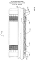
- Figure 1 is a cutaway view of a swellable packer according to one embodiment.
- Figure 2 is a cutaway view of a swellable packer according to another embodiment.
- Figure 3 is a side view of a support assembly for a swellable packer according to one embodiment.
- FIG. 1 illustrates a swellable packer 100 according to one embodiment.
- a swellable element 140 is disposed about a mandrel 110 along the longitudinal axis L.
- the swellable element 140 may be bonded to the mandrel 110 using bonding techniques known to the art or may use other techniques for attaching the swellable element 140 to the mandrel 110 .
- the swellable element 140 is disposed about a mandrel, in some embodiments a tubular, such as a base pipe, may be used instead of a mandrel.
- end rings 120A and 120B are disposed about the mandrel 110 at each end of the swellable element 140 .
- the end rings 120A/B are secured to the mandrel 110 , in one embodiment by screws that extend radially through the end rings 120A/B and into abutment with the mandrel 110 .
- Support assemblies 130A and 130B are disposed about the mandrel 110 between the swellable element 140 and the end rings 120A/B at opposing ends of the packer 100 .
- an additional elastomeric element may be positioned between the support assemblies 130A/B and the swellable element 140 .
- each support assembly 130 (shown most clearly in FIG. 3 ) comprises a support ring 300 defining a throughbore sized to accommodate the mandrel 110 .
- the support ring 300 is formed from a metal such as stainless steel, and comprises a neck portion 310 and a flared portion 320 .
- the neck portion 310 is received in a corresponding recess 122A/B in the end rings 120A/B , and abuts the end wall of the recess.
- the support assemblies 130A/B may be anchored to the mandrel 110 at attachment points 312 in the neck portion 310 , using any anchoring technique known to the art, including screws.
- the flared portion 320 extends radially and longitudinally on the mandrel 110 to define an internal volume when assembled, and the which accommodates a part of the swellable element 140 as illustrated in FIG. 1 .
- the support ring 300 comprises a concave inner surface that defines a cup, and the outer surface may be angled to define a conical part 330 and a cylindrical part 332 .
- the support ring 300 may be provided with circumferentially spaced slots 340 that extend from an outer edge 350 (distal the mandrel 110 ), through the flared portion 320 to a predetermined depth, to define leaves 360 in the flared portion 320 .
- the slots 350 facilitate deployment of the support assembly 130 , allowing opening of the slots 350 by pivoting or deformation of the leaves 360 .
- the slots 350 may for example be formed by water jet cutting or wire cutting.
- the flared portion 320 instead of slots forming leaves 360 that separate when expanded by expansion of the swellable element 140 , may be formed of a material that expands by stretching.
- An anchor area 370 is formed from the outer edge 350 on a portion of the flared portion 320 to a predetermined depth.
- the anchor area 370 comprises a plurality of wickers 375 formed into or onto the radially outward surface of the anchor area 370 .
- the wickers 375 may be formed of stainless steel or any other material of sufficient hardness to perform the desired anchoring function. The material is selected to be harder than the surrounding surface.
- the wickers 375 are generally shaped so that when engaged with the surrounding surface of the open hole or casing, they anchor the swellable element 140 to the surrounding surface, resisting movement.
- the anchor area 370 of support assembly 130A may have wickers 375 that resist movement in one direction along axis L, while the anchor area 370 of support assembly 130B may have wickers that resist movement in the other direction.
- the anchor area 370 of both support assemblies 130A/B may have wickers that resist movement in both axial directions.
- the anchor area 370 may use other techniques to provide a anchoring area, such as a roughened surface, embedded pieces of material that extend outwardly from the anchor area, etc. These techniques are illustrative and by way of example only, and any technique known to the art for forming an area to anchor against an opposed surface known to the art may be used in the anchor areas 370 .
- the swellable element 140 is formed from a swellable elastomeric material selected to increase in volume on exposure to a predetermined triggering fluid. Such materials are known in the art.
- the swellable elastomeric material is an ethylene propylene diene monomer (EPDM) rubber selected to swell in hydrocarbon fluids, but alternative embodiments may comprise materials which swell in aqueous fluids, or which swell in both hydrocarbon and aqueous fluids.
- EPDM ethylene propylene diene monomer
- FIG. 1 the apparatus is shown in a run-in configuration.
- the swellable element 140 is in an unswollen condition, and its outer diameter (OD) is approximately flush with the OD of the end rings 120A/B .
- the swellable packer 100 is exposed to the triggering fluid, which may be a fluid naturally present in the well, or may be a fluid injected or circulated in the well.
- the fluid diffuses into the swellable element 140 , causing it to increase in volume.
- the support assemblies 130A/B are flexible and shaped to conform to the ends of the swellable element 140 .
- the swellable element 140 expands radially outwardly to seal with the surrounding surface of the open hole or casing (not shown), but also expands axially into the support assemblies 130A/B .
- the increase in volume exerts an outward radial force on the support assemblies 130A/B , deforming the support assemblies 130A/B radially outwardly as urged by the swellable element 140 .
- the slots 340 open to deploy the support assembly 130A/B .
- the leaves 360 separate as the deformation continues, and the outer edge 350 and wicker section 370 spread out around the expanded swellable element 140 .
- This deformation and the swelling of the swellable element 140 urge the wicker section 370 into the surrounding surface of the open hole or casing.
- the pressure of the swellable element 140 keeps the wicker section 370 engaged with the surrounding open hold or casing, and the engaged wicker section provides additional resistive force, anchoring and preventing movement of the swellable packer 100 .
- the rings 130A/B additionally may serve as an anti-extrusion barrier, retaining the longitudinal end of the swellable element 140 as it swells and expands after insertion downhole in the presence of the triggering fluid.
- the support assemblies 130A/B function to mitigate the effects of forces on the swellable material that may otherwise adversely affect the seal.
- the support assemblies 130A/B are operable to expand to the full extent of the wellbore cross section, and contain and support the expanded swellable element 140 over the whole wellbore.
- the support assemblies 130A/B may also provide an extrusion barrier, mitigating or eliminating extrusion of the swellable material which may otherwise be caused by shear forces in the swellable material due to pressure differentials across the seal and axial forces on the mandrel 110.
- Axial forces due to pressure differentials or weight on the mandrel tend to be redirected through the support assembly 130 into the anchor areas 370 , thus increasing the holding ability of the anchor areas 370 .
- the concave shape of the support assemblies 130A/B helps capture longitudinal forces in the elastomer of the swellable element 140 and utilizes them to enhance the seal and the anchoring of the anchoring areas 370 .
- the anchor areas 370 may also be deformed compliantly against the surrounding surface in an open hole deployment, conforming to the open hole surface, and provides both containment of the volume of the swellable element 140 as well as increases holding and sealing ability.
- FIG. 2 is a cutaway view of a swellable packer 200 according to another embodiment.
- one or more body anchor areas 210 may be formed about the swellable element 140 distal to the ends of the swellable element 140 .
- FIG. 2 is a cutaway view of a swellable packer 200 according to another embodiment.
- one or more body anchor areas 210 may be formed about the swellable element 140 distal to the ends of the swellable element 140 .
- FIG. 2 for clarity, any number of body anchor areas 210 may be provided.
- the body anchor area 210 may be formed in the same way as the anchor area 370 of the support assembly or may use different construction techniques or materials.
- the materials used to form the components of the support assembly 130 may be varied according to the required application and performance.
- the assembly 130 may include components formed from materials selected from steels, plastics, epoxy resins, elastomers or natural rubbers of varying hardness, aluminum alloys, tin plate, coppers, brass, other metals, KEVLAR® or other composites, carbon fiber and others (KEVLAR® is a registered trademark of E. I. du Pont de Nemours and Company.). Any of a number of suitable manufacturing techniques may be used, including press forming and machining.
- FIG. 1 Although as shown in FIG. 1 , two support assemblies 130A/B are illustrated, embodiments can be deployed with only a single support assembly 130 on a desired end of the swellable element 140 .
- the body anchor areas 210 are formed as a ring with wickers formed of a material such as stainless steel, although other materials may be used that are of sufficient hardness to engage with the surrounding surface of the open hole or casing, typically being material selected to be harder than the surrounding surface.
- the body anchor areas 210 may be disposed about the swellable element 140 in such a way that radial swelling of the swellable element 140 urges the body anchor area against the surrounding surface of the open hole or casing, anchoring the swellable element 140 and increasing the holding ability of the swellable packer 200 .
- the body anchor areas 210 in one embodiment may be formed from a material that expands with the radial expansion of the swellable element 140.
- the body anchor areas 210 may be manufactured to break into section similar to the expansion of the leaves 360 of the support assemblies 130A/B described above. In either type of embodiment, the body anchor areas provide a similar gripping force when urged into the surrounding surface of the open hole or casing by the expansion of the swellable element 140 , anchoring the swellable element 140 and resisting movement of the swellable packer 100.
- the body anchor areas 210 may be formed as part of the swellable element 140 itself, such as by roughening an area of the outer surface of the swellable element 140 , so that when engaged with the surrounding surface, the rough and area anchors the swellable element 140 and resists movement of the swellable packer 100 .
- the body anchor areas 210 may be provided instead of using the anchor area 370 of support assemblies 130A/B , and may include placement of the body anchor areas 210 at one or both ends of the swellable element 140 , in addition to, or instead of placement as illustrated in FIG. 2 .
- the anti-extrusion functionality of the support assemblies 130A/B may be provided by end rings 120A/B or the support assemblies 130A/B may omit the anchor area 370 , but provide the anti-extrusion functionality.
- rings Although described above as rings, embodiments may use ribs or other separate elements instead of rings, replacing rings 130A/B or body anchor areas 210 .
- the body anchor areas 210 as described above are formed external to and as separate elements from the swellable element 140 .
- the body anchor areas 210 may be formed internal to the swellable element 140 .
- the body anchor areas 210 may be formed close to the radial outward surface of the swellable element 140 so that expansion of the swellable element 140 causes a pinching of the material of the swellable element 140 between the internally formed body anchor areas 210 and the surface of the open hole or casing.
- any desired patterns or formations of elements may be used as part of the body anchor areas 210 or the gripper rings 130A/B to provide an anchoring surface appropriate to the application for which the swellable packer 100 or 200 is to be employed.
- the end rings 120A/B may be omitted.
- FIGs. 1-3 illustrate anchoring areas that are formed circumferentially to the swellable element
- other embodiments may provide anchoring areas that extend longitudinally as ribs along some or all of the swellable element 140 .
- a plurality of these longitudinal anchoring areas may be spaced circumferentially about the swellable element 140 as desired.
Landscapes
- Life Sciences & Earth Sciences (AREA)
- Engineering & Computer Science (AREA)
- Geology (AREA)
- Mining & Mineral Resources (AREA)
- Physics & Mathematics (AREA)
- Environmental & Geological Engineering (AREA)
- Fluid Mechanics (AREA)
- General Life Sciences & Earth Sciences (AREA)
- Geochemistry & Mineralogy (AREA)
- Piles And Underground Anchors (AREA)
- Laying Of Electric Cables Or Lines Outside (AREA)
Applications Claiming Priority (1)
| Application Number | Priority Date | Filing Date | Title |
|---|---|---|---|
| US12/842,510 US8997854B2 (en) | 2010-07-23 | 2010-07-23 | Swellable packer anchors |
Publications (2)
| Publication Number | Publication Date |
|---|---|
| EP2410120A2 true EP2410120A2 (de) | 2012-01-25 |
| EP2410120A3 EP2410120A3 (de) | 2013-08-14 |
Family
ID=44279191
Family Applications (1)
| Application Number | Title | Priority Date | Filing Date |
|---|---|---|---|
| EP20110166712 Withdrawn EP2410120A3 (de) | 2010-07-23 | 2011-05-19 | Quellfähigen Pakerverankerungen |
Country Status (5)
| Country | Link |
|---|---|
| US (1) | US8997854B2 (de) |
| EP (1) | EP2410120A3 (de) |
| AU (1) | AU2011202331B2 (de) |
| CA (1) | CA2741238C (de) |
| RU (1) | RU2477365C1 (de) |
Cited By (3)
| Publication number | Priority date | Publication date | Assignee | Title |
|---|---|---|---|---|
| WO2014182301A1 (en) * | 2013-05-09 | 2014-11-13 | Halliburton Energy Services, Inc. | Swellable packer with reinforcement and anti-extrusion features |
| WO2014177865A3 (en) * | 2013-05-03 | 2015-04-09 | Tendeka B.V. | A packer and associated methods, seal ring and fixing ring |
| RU2768349C2 (ru) * | 2018-06-13 | 2022-03-23 | Халлибертон Энерджи Сервисез, Инк. | Узел пакера, предназначенный для использования в подземной скважине, способ его конструирования и скважинная система, содержащая узел пакера |
Families Citing this family (65)
| Publication number | Priority date | Publication date | Assignee | Title |
|---|---|---|---|---|
| CA2856053A1 (en) * | 2011-11-18 | 2013-06-27 | Ruma Products Holding B.V. | Seal sleeve and assembly including such a seal sleeve |
| US9163474B2 (en) * | 2012-11-16 | 2015-10-20 | Baker Hughes Incorporated | Shape memory cup seal and method of use |
| WO2014089150A1 (en) * | 2012-12-07 | 2014-06-12 | Schlumberger Canada Limited | Fold back swell packer |
| US9587458B2 (en) | 2013-03-12 | 2017-03-07 | Weatherford Technology Holdings, Llc | Split foldback rings with anti-hooping band |
| CA2919009C (en) * | 2013-07-22 | 2019-11-26 | Tam International, Inc. | Grooved swellable packer |
| WO2015013278A1 (en) | 2013-07-22 | 2015-01-29 | Tam International, Inc. | Swellable casing anchor |
| RU2631454C1 (ru) * | 2013-11-06 | 2017-09-22 | Халлибертон Энерджи Сервисез, Инк. | Набухающий уплотнитель с опорой |
| US9995103B2 (en) | 2015-10-20 | 2018-06-12 | Baker Hughes, A Ge Company, Llc | Extended reach anti-extrusion ring assembly with anchoring feature |
| RU2605249C1 (ru) * | 2015-11-09 | 2016-12-20 | Публичное акционерное общество "Татнефть" им. В.Д. Шашина | Пакер скважинный набухающий |
| US10704355B2 (en) | 2016-01-06 | 2020-07-07 | Baker Hughes, A Ge Company, Llc | Slotted anti-extrusion ring assembly |
| RU2605242C1 (ru) * | 2016-01-11 | 2016-12-20 | Публичное акционерное общество "Татнефть" имени В.Д. Шашина | Пакер скважинный набухающий |
| WO2017156129A1 (en) * | 2016-03-08 | 2017-09-14 | Elite Elastomers, Inc. | Wellbore packer and method of making same |
| US10989014B2 (en) * | 2016-10-24 | 2021-04-27 | Baker Hughes Oilfield Operations, Llc | Perforation blocking sleeve for well restimulation |
| US10526864B2 (en) | 2017-04-13 | 2020-01-07 | Baker Hughes, A Ge Company, Llc | Seal backup, seal system and wellbore system |
| US10100245B1 (en) | 2017-05-15 | 2018-10-16 | Saudi Arabian Oil Company | Enhancing acid fracture conductivity |
| CA3069867C (en) * | 2017-07-13 | 2022-07-19 | Baker Hughes, A Ge Company, Llc | Slotted backup ring assembly |
| US10370935B2 (en) | 2017-07-14 | 2019-08-06 | Baker Hughes, A Ge Company, Llc | Packer assembly including a support ring |
| US10907438B2 (en) | 2017-09-11 | 2021-02-02 | Baker Hughes, A Ge Company, Llc | Multi-layer backup ring |
| US10907437B2 (en) | 2019-03-28 | 2021-02-02 | Baker Hughes Oilfield Operations Llc | Multi-layer backup ring |
| US10689942B2 (en) | 2017-09-11 | 2020-06-23 | Baker Hughes, A Ge Company, Llc | Multi-layer packer backup ring with closed extrusion gaps |
| US10677014B2 (en) | 2017-09-11 | 2020-06-09 | Baker Hughes, A Ge Company, Llc | Multi-layer backup ring including interlock members |
| US10655443B2 (en) | 2017-09-21 | 2020-05-19 | Saudi Arabian Oil Company | Pulsed hydraulic fracturing with geopolymer precursor fluids |
| RU182236U1 (ru) * | 2018-01-09 | 2018-08-09 | Государственное бюджетное образовательное учреждение высшего образования "Альметьевский государственный нефтяной институт" | Набухающий уплотнитель в пакере со шлипсовым механизмом |
| BR112020013879A2 (pt) * | 2018-02-27 | 2020-12-01 | Halliburton Energy Services, Inc. | sistema de válvula, e, método para instalar um sistema de válvula em um revestimento usado em um ambiente de fundo de poço |
| US10767452B2 (en) | 2018-06-06 | 2020-09-08 | Saudi Arabian Oil Company | Liner installation with inflatable packer |
| US10934814B2 (en) | 2018-06-06 | 2021-03-02 | Saudi Arabian Oil Company | Liner installation with inflatable packer |
| SG11202105144WA (en) * | 2019-02-05 | 2021-06-29 | Halliburton Energy Services Inc | Variable density element retainer for use downhole |
| WO2021046294A1 (en) | 2019-09-05 | 2021-03-11 | Saudi Arabian Oil Company | Propping open hydraulic fractures |
| US11346177B2 (en) | 2019-12-04 | 2022-05-31 | Saudi Arabian Oil Company | Repairable seal assemblies for oil and gas applications |
| US11142978B2 (en) | 2019-12-12 | 2021-10-12 | Baker Hughes Oilfield Operations Llc | Packer assembly including an interlock feature |
| US11352548B2 (en) | 2019-12-31 | 2022-06-07 | Saudi Arabian Oil Company | Viscoelastic-surfactant treatment fluids having oxidizer |
| GB2605062B (en) | 2020-01-17 | 2024-09-25 | Halliburton Energy Services Inc | Voltage to accelerate/decelerate expandable metal |
| MX2022006306A (es) | 2020-01-17 | 2022-06-22 | Halliburton Energy Services Inc | Calentadores para acelerar la colocacion de metal expandible. |
| GB2606899B (en) | 2020-02-28 | 2024-01-17 | Halliburton Energy Services Inc | Textured surfaces of expanding metal for centralizer, mixing, and differential sticking |
| US11339636B2 (en) | 2020-05-04 | 2022-05-24 | Saudi Arabian Oil Company | Determining the integrity of an isolated zone in a wellbore |
| AU2021324947B2 (en) | 2020-08-13 | 2025-11-20 | Halliburton Energy Services, Inc. | A valve including an expandable metal seal |
| US11519767B2 (en) | 2020-09-08 | 2022-12-06 | Saudi Arabian Oil Company | Determining fluid parameters |
| US11920469B2 (en) | 2020-09-08 | 2024-03-05 | Saudi Arabian Oil Company | Determining fluid parameters |
| US11867028B2 (en) | 2021-01-06 | 2024-01-09 | Saudi Arabian Oil Company | Gauge cutter and sampler apparatus |
| US11530597B2 (en) | 2021-02-18 | 2022-12-20 | Saudi Arabian Oil Company | Downhole wireless communication |
| US11603756B2 (en) | 2021-03-03 | 2023-03-14 | Saudi Arabian Oil Company | Downhole wireless communication |
| US11644351B2 (en) | 2021-03-19 | 2023-05-09 | Saudi Arabian Oil Company | Multiphase flow and salinity meter with dual opposite handed helical resonators |
| US11585176B2 (en) | 2021-03-23 | 2023-02-21 | Saudi Arabian Oil Company | Sealing cracked cement in a wellbore casing |
| AU2021440755A1 (en) | 2021-04-12 | 2023-08-24 | Halliburton Energy Services, Inc. | Expandable metal as backup for elastomeric elements |
| US11619114B2 (en) | 2021-04-15 | 2023-04-04 | Saudi Arabian Oil Company | Entering a lateral branch of a wellbore with an assembly |
| US11913464B2 (en) | 2021-04-15 | 2024-02-27 | Saudi Arabian Oil Company | Lubricating an electric submersible pump |
| US12326060B2 (en) | 2021-05-21 | 2025-06-10 | Halliburton Energy Services, Inc. | Wellbore anchor including one or more activation chambers |
| NO20231086A1 (en) | 2021-05-28 | 2023-10-13 | Halliburton Energy Services Inc | Rapid setting expandable metal |
| BR112023020428A2 (pt) | 2021-05-28 | 2023-12-12 | Halliburton Energy Services Inc | Ferramenta de fundo de poço, método para vedação, e, sistema de poço |
| NO20231085A1 (en) | 2021-05-29 | 2023-10-13 | Halliburton Energy Services Inc | Using expandable metal as an alternate to existing metal to metal seals |
| WO2022255988A1 (en) | 2021-06-01 | 2022-12-08 | Halliburton Energy Services, Inc. | Expanding metal used in forming support structures |
| US12378832B2 (en) * | 2021-10-05 | 2025-08-05 | Halliburton Energy Services, Inc. | Expandable metal sealing/anchoring tool |
| US12071589B2 (en) | 2021-10-07 | 2024-08-27 | Saudi Arabian Oil Company | Water-soluble graphene oxide nanosheet assisted high temperature fracturing fluid |
| US20230160272A1 (en) * | 2021-11-22 | 2023-05-25 | Baker Hughes Oilfield Operations Llc | Anchor for tool, method for managing a borehole, and system |
| US11867012B2 (en) | 2021-12-06 | 2024-01-09 | Saudi Arabian Oil Company | Gauge cutter and sampler apparatus |
| US12025589B2 (en) | 2021-12-06 | 2024-07-02 | Saudi Arabian Oil Company | Indentation method to measure multiple rock properties |
| US11994016B2 (en) | 2021-12-09 | 2024-05-28 | Saudi Arabian Oil Company | Downhole phase separation in deviated wells |
| US12012550B2 (en) | 2021-12-13 | 2024-06-18 | Saudi Arabian Oil Company | Attenuated acid formulations for acid stimulation |
| US12085687B2 (en) | 2022-01-10 | 2024-09-10 | Saudi Arabian Oil Company | Model-constrained multi-phase virtual flow metering and forecasting with machine learning |
| US11834923B2 (en) * | 2022-02-17 | 2023-12-05 | Tam International, Inc. | High pressure swellable packer |
| US12203333B2 (en) * | 2022-06-06 | 2025-01-21 | Halliburton Energy Services, Inc. | Composite wellbore sealing device |
| US12258828B2 (en) | 2022-06-15 | 2025-03-25 | Halliburton Energy Services, Inc. | Sealing/anchoring tool employing a hydraulically deformable member and an expandable metal circlet |
| US12209470B2 (en) | 2022-11-17 | 2025-01-28 | Wireless Instrumentation Systems AS | Woven sleeves and related methods of constraining a well tool |
| US12385340B2 (en) | 2022-12-05 | 2025-08-12 | Halliburton Energy Services, Inc. | Reduced backlash sealing/anchoring assembly |
| US12203366B2 (en) | 2023-05-02 | 2025-01-21 | Saudi Arabian Oil Company | Collecting samples from wellbores |
Family Cites Families (30)
| Publication number | Priority date | Publication date | Assignee | Title |
|---|---|---|---|---|
| US49544A (en) | 1865-08-22 | Improvement in packing for oil-well tubes | ||
| US2885009A (en) * | 1956-01-23 | 1959-05-05 | Baker Oil Tools Inc | Cold flow preventing packing structures |
| US3035639A (en) * | 1957-05-27 | 1962-05-22 | Brown | Hydraulically-actuated well packer |
| US2970651A (en) * | 1957-08-21 | 1961-02-07 | Jersey Prod Res Co | Hydraulically inflatable anchors |
| US3085627A (en) * | 1958-08-15 | 1963-04-16 | Lynes Inc | Inflatable packer or element |
| US3097696A (en) * | 1961-07-27 | 1963-07-16 | Jersey Prod Res Co | Self-expanding retrievable or permanent bridge plug |
| US4375240A (en) * | 1980-12-08 | 1983-03-01 | Hughes Tool Company | Well packer |
| US5027894A (en) * | 1990-05-01 | 1991-07-02 | Davis-Lynch, Inc. | Through the tubing bridge plug |
| US5220959A (en) * | 1991-09-24 | 1993-06-22 | The Gates Rubber Company | Gripping inflatable packer |
| US5197542A (en) * | 1992-03-31 | 1993-03-30 | Davis-Lynch, Inc. | Well packer |
| US6695050B2 (en) * | 2002-06-10 | 2004-02-24 | Halliburton Energy Services, Inc. | Expandable retaining shoe |
| CA2547007C (en) * | 2003-11-25 | 2008-08-26 | Baker Hughes Incorporated | Swelling layer inflatable |
| GB2428058B (en) * | 2004-03-12 | 2008-07-30 | Schlumberger Holdings | Sealing system and method for use in a well |
| GB0413042D0 (en) | 2004-06-11 | 2004-07-14 | Petrowell Ltd | Sealing system |
| NO327157B1 (no) * | 2005-05-09 | 2009-05-04 | Easy Well Solutions As | Forankringsanordning for en ringromspakning med et forste andre endeomradet og anbrakt pa et rorformet element |
| US7661471B2 (en) * | 2005-12-01 | 2010-02-16 | Baker Hughes Incorporated | Self energized backup system for packer sealing elements |
| US7431098B2 (en) * | 2006-01-05 | 2008-10-07 | Schlumberger Technology Corporation | System and method for isolating a wellbore region |
| US7387158B2 (en) | 2006-01-18 | 2008-06-17 | Baker Hughes Incorporated | Self energized packer |
| CA2681603C (en) * | 2006-03-23 | 2014-05-13 | Petrowell Limited | Improved packer |
| EP2086762A2 (de) | 2006-10-20 | 2009-08-12 | Halliburton Energy Services, Inc. | Quellfähige packerausführung für durchgehende oder segmentierte rohre |
| GB2444060B (en) * | 2006-11-21 | 2008-12-17 | Swelltec Ltd | Downhole apparatus and method |
| US7806193B2 (en) * | 2007-06-06 | 2010-10-05 | Baker Hughes Incorporated | Swellable packer with back-up systems |
| GB0712345D0 (en) * | 2007-06-26 | 2007-08-01 | Metcalfe Paul D | Downhole apparatus |
| US7931092B2 (en) | 2008-02-13 | 2011-04-26 | Stowe Woodward, L.L.C. | Packer element with recesses for downwell packing system and method of its use |
| WO2009105575A1 (en) * | 2008-02-19 | 2009-08-27 | Weatherford/Lamb, Inc. | Expandable packer |
| US7806192B2 (en) * | 2008-03-25 | 2010-10-05 | Foster Anthony P | Method and system for anchoring and isolating a wellbore |
| US7938176B2 (en) * | 2008-08-15 | 2011-05-10 | Schlumberger Technology Corporation | Anti-extrusion device for swell rubber packer |
| US8157019B2 (en) * | 2009-03-27 | 2012-04-17 | Baker Hughes Incorporated | Downhole swellable sealing system and method |
| GB2469870A (en) * | 2009-05-01 | 2010-11-03 | Swelltec Ltd | Support assembly for a downhole tool |
| US20120073834A1 (en) * | 2010-09-28 | 2012-03-29 | Weatherford/Lamb, Inc. | Friction Bite with Swellable Elastomer Elements |
-
2010
- 2010-07-23 US US12/842,510 patent/US8997854B2/en not_active Expired - Fee Related
-
2011
- 2011-05-19 EP EP20110166712 patent/EP2410120A3/de not_active Withdrawn
- 2011-05-19 AU AU2011202331A patent/AU2011202331B2/en not_active Ceased
- 2011-05-27 CA CA 2741238 patent/CA2741238C/en not_active Expired - Fee Related
- 2011-07-22 RU RU2011130848/03A patent/RU2477365C1/ru not_active IP Right Cessation
Non-Patent Citations (1)
| Title |
|---|
| None |
Cited By (11)
| Publication number | Priority date | Publication date | Assignee | Title |
|---|---|---|---|---|
| WO2014177865A3 (en) * | 2013-05-03 | 2015-04-09 | Tendeka B.V. | A packer and associated methods, seal ring and fixing ring |
| CN105452596A (zh) * | 2013-05-03 | 2016-03-30 | 唐德卡股份有限公司 | 封隔器及相关方法、密封环和固定环 |
| AU2014261214B2 (en) * | 2013-05-03 | 2018-02-08 | Tendeka B.V. | A packer and associated methods, seal ring and fixing ring |
| US10370929B2 (en) | 2013-05-03 | 2019-08-06 | Tendeka B.V. | Packer and associated methods, seal ring and fixing ring |
| WO2014182301A1 (en) * | 2013-05-09 | 2014-11-13 | Halliburton Energy Services, Inc. | Swellable packer with reinforcement and anti-extrusion features |
| GB2529084A (en) * | 2013-05-09 | 2016-02-10 | Halliburton Energy Services Inc | Swellable packer with reinforcement and anti-extrusion features |
| GB2529084B (en) * | 2013-05-09 | 2017-03-01 | Halliburton Energy Services Inc | Swellable packer with reinforcement and anti-extrusion features |
| RU2658855C2 (ru) * | 2013-05-09 | 2018-06-25 | Халлибертон Энерджи Сервисез, Инк. | Разбухающий пакер с усиливающим элементом и антиэкструзионными характеристиками |
| US10287846B2 (en) | 2013-05-09 | 2019-05-14 | Halliburton Energy Services, Inc. | Swellable packer with reinforcement and anti-extrusion features |
| US11268342B2 (en) | 2013-05-09 | 2022-03-08 | Halliburton Energy Services, Inc. | Swellable packer with reinforcement and anti-extrusion features |
| RU2768349C2 (ru) * | 2018-06-13 | 2022-03-23 | Халлибертон Энерджи Сервисез, Инк. | Узел пакера, предназначенный для использования в подземной скважине, способ его конструирования и скважинная система, содержащая узел пакера |
Also Published As
| Publication number | Publication date |
|---|---|
| CA2741238A1 (en) | 2012-01-23 |
| AU2011202331A1 (en) | 2012-02-09 |
| US8997854B2 (en) | 2015-04-07 |
| RU2477365C1 (ru) | 2013-03-10 |
| AU2011202331B2 (en) | 2013-02-14 |
| US20120018143A1 (en) | 2012-01-26 |
| RU2011130848A (ru) | 2013-01-27 |
| EP2410120A3 (de) | 2013-08-14 |
| CA2741238C (en) | 2013-01-29 |
Similar Documents
| Publication | Publication Date | Title |
|---|---|---|
| CA2741238C (en) | Swellable packer anchors | |
| CA2701489C (en) | Improvements to swellable apparatus | |
| CA2752398C (en) | Friction bite with swellable elastomer elements | |
| EP2558677B1 (de) | System mit sequenzierten verpackungselementen | |
| US8087459B2 (en) | Packer providing multiple seals and having swellable element isolatable from the wellbore | |
| US7909110B2 (en) | Anchoring and sealing system for cased hole wells | |
| CA2752345C (en) | Universal backup for swellable packers | |
| EP2436874B1 (de) | Bohrgestänge | |
| US20110220356A1 (en) | Multiple stage cementing tool with expandable sealing element | |
| AU2017248571B2 (en) | Improvements to swellable apparatus | |
| AU2013200294B2 (en) | Improvements to swellable apparatus | |
| CA2821318C (en) | Tubing expander with plural elastomeric sections | |
| CA2879895A1 (en) | Sealing apparatus and method |
Legal Events
| Date | Code | Title | Description |
|---|---|---|---|
| AK | Designated contracting states |
Kind code of ref document: A2 Designated state(s): AL AT BE BG CH CY CZ DE DK EE ES FI FR GB GR HR HU IE IS IT LI LT LU LV MC MK MT NL NO PL PT RO RS SE SI SK SM TR |
|
| AX | Request for extension of the european patent |
Extension state: BA ME |
|
| PUAI | Public reference made under article 153(3) epc to a published international application that has entered the european phase |
Free format text: ORIGINAL CODE: 0009012 |
|
| PUAL | Search report despatched |
Free format text: ORIGINAL CODE: 0009013 |
|
| AK | Designated contracting states |
Kind code of ref document: A3 Designated state(s): AL AT BE BG CH CY CZ DE DK EE ES FI FR GB GR HR HU IE IS IT LI LT LU LV MC MK MT NL NO PL PT RO RS SE SI SK SM TR |
|
| AX | Request for extension of the european patent |
Extension state: BA ME |
|
| RIC1 | Information provided on ipc code assigned before grant |
Ipc: E21B 33/12 20060101AFI20130710BHEP |
|
| 17P | Request for examination filed |
Effective date: 20140214 |
|
| RBV | Designated contracting states (corrected) |
Designated state(s): AL AT BE BG CH CY CZ DE DK EE ES FI FR GB GR HR HU IE IS IT LI LT LU LV MC MK MT NL NO PL PT RO RS SE SI SK SM TR |
|
| 17Q | First examination report despatched |
Effective date: 20150323 |
|
| RAP1 | Party data changed (applicant data changed or rights of an application transferred) |
Owner name: WEATHERFORD TECHNOLOGY HOLDINGS, LLC |
|
| GRAP | Despatch of communication of intention to grant a patent |
Free format text: ORIGINAL CODE: EPIDOSNIGR1 |
|
| INTG | Intention to grant announced |
Effective date: 20180823 |
|
| STAA | Information on the status of an ep patent application or granted ep patent |
Free format text: STATUS: THE APPLICATION IS DEEMED TO BE WITHDRAWN |
|
| 18D | Application deemed to be withdrawn |
Effective date: 20190103 |