EP2409067B1 - Aseptic coupling devices - Google Patents
Aseptic coupling devices Download PDFInfo
- Publication number
- EP2409067B1 EP2409067B1 EP10709364.3A EP10709364A EP2409067B1 EP 2409067 B1 EP2409067 B1 EP 2409067B1 EP 10709364 A EP10709364 A EP 10709364A EP 2409067 B1 EP2409067 B1 EP 2409067B1
- Authority
- EP
- European Patent Office
- Prior art keywords
- coupling device
- aseptic coupling
- aseptic
- inner member
- membrane
- Prior art date
- Legal status (The legal status is an assumption and is not a legal conclusion. Google has not performed a legal analysis and makes no representation as to the accuracy of the status listed.)
- Active
Links
Images














Classifications
-
- F—MECHANICAL ENGINEERING; LIGHTING; HEATING; WEAPONS; BLASTING
- F16—ENGINEERING ELEMENTS AND UNITS; GENERAL MEASURES FOR PRODUCING AND MAINTAINING EFFECTIVE FUNCTIONING OF MACHINES OR INSTALLATIONS; THERMAL INSULATION IN GENERAL
- F16L—PIPES; JOINTS OR FITTINGS FOR PIPES; SUPPORTS FOR PIPES, CABLES OR PROTECTIVE TUBING; MEANS FOR THERMAL INSULATION IN GENERAL
- F16L37/00—Couplings of the quick-acting type
-
- A—HUMAN NECESSITIES
- A61—MEDICAL OR VETERINARY SCIENCE; HYGIENE
- A61M—DEVICES FOR INTRODUCING MEDIA INTO, OR ONTO, THE BODY; DEVICES FOR TRANSDUCING BODY MEDIA OR FOR TAKING MEDIA FROM THE BODY; DEVICES FOR PRODUCING OR ENDING SLEEP OR STUPOR
- A61M39/00—Tubes, tube connectors, tube couplings, valves, access sites or the like, specially adapted for medical use
- A61M39/10—Tube connectors or tube couplings
- A61M39/16—Tube connectors or tube couplings having provision for disinfection or sterilisation
- A61M39/18—Methods or apparatus for making the connection under sterile conditions, i.e. sterile docking
-
- A—HUMAN NECESSITIES
- A61—MEDICAL OR VETERINARY SCIENCE; HYGIENE
- A61M—DEVICES FOR INTRODUCING MEDIA INTO, OR ONTO, THE BODY; DEVICES FOR TRANSDUCING BODY MEDIA OR FOR TAKING MEDIA FROM THE BODY; DEVICES FOR PRODUCING OR ENDING SLEEP OR STUPOR
- A61M39/00—Tubes, tube connectors, tube couplings, valves, access sites or the like, specially adapted for medical use
- A61M39/20—Closure caps or plugs for connectors or open ends of tubes
-
- F—MECHANICAL ENGINEERING; LIGHTING; HEATING; WEAPONS; BLASTING
- F16—ENGINEERING ELEMENTS AND UNITS; GENERAL MEASURES FOR PRODUCING AND MAINTAINING EFFECTIVE FUNCTIONING OF MACHINES OR INSTALLATIONS; THERMAL INSULATION IN GENERAL
- F16L—PIPES; JOINTS OR FITTINGS FOR PIPES; SUPPORTS FOR PIPES, CABLES OR PROTECTIVE TUBING; MEANS FOR THERMAL INSULATION IN GENERAL
- F16L37/00—Couplings of the quick-acting type
- F16L37/08—Couplings of the quick-acting type in which the connection between abutting or axially overlapping ends is maintained by locking members
- F16L37/10—Couplings of the quick-acting type in which the connection between abutting or axially overlapping ends is maintained by locking members using a rotary external sleeve or ring on one part
- F16L37/113—Couplings of the quick-acting type in which the connection between abutting or axially overlapping ends is maintained by locking members using a rotary external sleeve or ring on one part the male part having lugs on its periphery penetrating into the corresponding slots provided in the female part
-
- F—MECHANICAL ENGINEERING; LIGHTING; HEATING; WEAPONS; BLASTING
- F16—ENGINEERING ELEMENTS AND UNITS; GENERAL MEASURES FOR PRODUCING AND MAINTAINING EFFECTIVE FUNCTIONING OF MACHINES OR INSTALLATIONS; THERMAL INSULATION IN GENERAL
- F16L—PIPES; JOINTS OR FITTINGS FOR PIPES; SUPPORTS FOR PIPES, CABLES OR PROTECTIVE TUBING; MEANS FOR THERMAL INSULATION IN GENERAL
- F16L37/00—Couplings of the quick-acting type
- F16L37/28—Couplings of the quick-acting type with fluid cut-off means
- F16L37/30—Couplings of the quick-acting type with fluid cut-off means with fluid cut-off means in each of two pipe-end fittings
-
- F—MECHANICAL ENGINEERING; LIGHTING; HEATING; WEAPONS; BLASTING
- F16—ENGINEERING ELEMENTS AND UNITS; GENERAL MEASURES FOR PRODUCING AND MAINTAINING EFFECTIVE FUNCTIONING OF MACHINES OR INSTALLATIONS; THERMAL INSULATION IN GENERAL
- F16L—PIPES; JOINTS OR FITTINGS FOR PIPES; SUPPORTS FOR PIPES, CABLES OR PROTECTIVE TUBING; MEANS FOR THERMAL INSULATION IN GENERAL
- F16L2201/00—Special arrangements for pipe couplings
- F16L2201/40—Special arrangements for pipe couplings for special environments
- F16L2201/44—Special arrangements for pipe couplings for special environments sterile
-
- Y—GENERAL TAGGING OF NEW TECHNOLOGICAL DEVELOPMENTS; GENERAL TAGGING OF CROSS-SECTIONAL TECHNOLOGIES SPANNING OVER SEVERAL SECTIONS OF THE IPC; TECHNICAL SUBJECTS COVERED BY FORMER USPC CROSS-REFERENCE ART COLLECTIONS [XRACs] AND DIGESTS
- Y10—TECHNICAL SUBJECTS COVERED BY FORMER USPC
- Y10T—TECHNICAL SUBJECTS COVERED BY FORMER US CLASSIFICATION
- Y10T29/00—Metal working
- Y10T29/49—Method of mechanical manufacture
- Y10T29/49826—Assembling or joining
Definitions
- Aseptic coupling devices can be used to connect two or more sterilized pathways.
- aseptic coupling devices can be used to couple a fluid pathway from a first piece of processing equipment or container to a fluid pathway from a second piece of processing equipment or container to establish a sterile pathway for fluid transfer therebetween.
- Typical aseptic coupling devices require a "dry-to-dry” or “dry connection” that is created using one or more pathway clamping devices placed upstream of the aseptic coupling devices so that the aseptic coupling devices are kept free of fluid while the connection between the aseptic coupling devices is made. Once the sterile connection between the aseptic coupling devices is made, the clamping devices are removed to allow fluid to flow through the aseptic coupling devices.
- an aseptic coupling device includes an inner member defining a fluid passage therethrough, a seal member coupled to a front surface of the inner member, a membrane coupled to the front surface of the inner member to cover the seal member, and a locking ring positioned to rotate about the inner member.
- the inner member is sized to be received in a member of another aseptic coupling device to form a pre-coupled state.
- the seal member engages a second seal member of the other aseptic coupling device, and, upon turning of the locking ring, the seal member and the WO 2006/117138 describes a connector comprising: a fluid leadthrough; a contact device; an essentially planar contact surface and; a fluid leadthrough opening, which is designed for leading fluid though, the fluid leadthrough opening passing through the contact surface; a sterile covering designed for sterilely covering, at least in part, the contact surface and/or an end of the fluid leadthrough opening facing the contact surface, and; a coupling device, which is designed for engaging with a complementary coupling device of a complementary connector along a coupling direction, the coupling device being essentially parallel to the contact surface .
- US 4,022,496 describes a coupling for closed fluid systems, such as refrigeration systems, wherein components of the refrigeration system may be precharged with refrigerant, and upon interconnection of the couplings communication between the components is established.
- the couplings include male and female members each having a passage sealed by a frangible diaphragm.
- the male member includes a tubular extension having an outer end sealed by a diaphragm whose periphery is axially slidably mounted upon the extension and interconnection of the coupling members engages the male member diaphragm with an abutment surface on the female member, preferably the female diaphragm, restraining the male diaphragm from axial displacement as the members are interconnected.
- the male extension passes through the diaphragms upon both members piercing and folding the ruptured diaphragms upon the exterior surface of the extension completely clearing the passage defined between the coupling members.
- the end of the extension makes metal-to-metal contact with an annular seal defined on the female member to establish a completed seal after completion of coupling member assembly.
- an aseptic coupling device includes an inner member defining a fluid passage therethrough, a seal member coupled to a front surface of the inner member, a membrane coupled to the front surface of the inner member to cover the seal member, and a locking ring positioned to rotate about the inner member.
- the inner member is sized to be received in a member of another aseptic coupling device to form a pre-coupled state.
- the seal member engages a second seal member of the other aseptic coupling device, and, upon turning of the locking ring, the seal member and the second seal member are compressed to form a coupled state in which a sterile flow path is created between the aseptic device and the other aseptic device.
- an aseptic coupling device includes a main body defining a fluid passage therethrough, a front portion coupled to the main body, the front portion defining a plurality of channels therein, a seal member coupled to a front surface of the main body, a membrane coupled to the front surface of the main body to cover the seal member, and a slot defined in the main body sized to receive a clip.
- the front portion is sized to a receive portion of another aseptic coupling device so that the clip engages the other aseptic coupling device to form a pre-coupled state.
- the seal member engages a second seal member of the other aseptic device, and, upon turning of a locking ring on the other aseptic coupling device, barbs of the locking ring are received within the channels of the front portion to compress the seal member with the second seal member to form a coupled state in which a sterile flow path is created between the aseptic coupling device and the other aseptic coupling device.
- a method for forming a sterile connection includes: inserting a first aseptic coupling device into a second aseptic coupling device; removing a first membrane from the first aseptic coupling device and a second membrane from the second aseptic coupling device; and rotating a locking clip on the first aseptic coupling device to compress a first seal member of the first aseptic coupling device with a second seal member of the second aseptic coupling device to form a sterile fluid passageway.
- the term "sterilize” means a process of freeing, to a specified degree, a surface or volume from microorganisms.
- the sterility of various components can be achieved using one or more sterilization techniques, including gamma irradiation, E-beam, ethylene oxide (EtO), and/or autoclave technologies.
- the term "aseptic” refers to any process that maintains a sterilized surface or volume.
- fluid means any substance that can be made to flow including, but is not limited to, liquids, gases, granular or powdered solids, mixtures or emulsions of two or more fluids, suspensions of solids within liquids or gases, etc.
- System 100 includes a first piece of processing equipment 110 and a second piece of processing equipment 120.
- equipment 110 and 120 are bioreactors including biomaterial.
- equipment 110 and 120 can be other apparatuses that require a sterile connection therebetween such as, for example, a bioreactor and a media bag or other receptacle.
- Equipment 110 includes a fluid pathway 112 extending therefrom that is terminated by an aseptic coupling arrangement 121 including a first aseptic coupling device 114.
- equipment 120 includes a fluid pathway 122 extending therefrom that is terminated by a second aseptic coupling device 124 of the aseptic coupling arrangement 121.
- the environment within pathways 112 and 122 and aseptic coupling devices 114 and 124 are sterile.
- Aseptic coupling device 114 can be connected to aseptic coupling device 124. Once aseptic coupling device 114 is connected to aseptic coupling device 124, a sterile fluid pathway is established between equipment 110 and equipment 120. Once the sterile fluid pathway is established, fluid can be transferred from equipment 110 to equipment 120, or vice versa.
- aseptic coupling devices 114 and 124 are shown in a pre-coupled state. In this state, the aseptic coupling devices 114, 124 are connected to one another. However, a sterile flow path has not yet been created because membranes associated with the aseptic coupling devices 114, 124 have not yet been removed.
- aseptic coupling device 114 is a male coupling device
- aseptic coupling device 124 is a female coupling device.
- the devices 114, 124 are keyed so that the devices 114, 124 can only be coupled in one manner, as described below. In alternative embodiments, other configurations are possible.
- the male aseptic coupling device 114 includes an inner member 201, a locking ring 202, and a membrane 204. See Figures 9-13 .
- Inner member 201 defines a fluid passage 502 through aseptic coupling device 114. Inner member 201 is coupled to a portion 214. In the example shown, portion 214 is barbed so that portion 214 can be connected to a fluid pathway (e.g., 112) such as a hose. Inner member 201 also includes a circular channel 504 that is formed to allow inner member 201 to be rotatably coupled to locking ring 202, as described below.
- Inner member 201 also defines a channel 304. See Figures 8-10 .
- Channel 304 is sized to receive a clip 212 (see Figure 18 ) that is used to couple aseptic coupling device 114 to aseptic coupling device 124.
- Membrane 204 is coupled, using, for example, an adhesive, to a front surface 802 of inner member 201.
- front surface 802 includes an opening 804. Opening 804 allows fluid flow through inner member 201.
- Front surface 802 forms a generally "D" shape and surrounds the opening 804.
- An upper portion 809 of the front surface 802 allows membrane 204 to extend beyond opening 804 so that as membrane 204 is removed, the sterility of opening 804 is maintained even if membranes 204, 206 are pulled at different rates, as described below.
- Recess portions 806 and 808 are relief areas that minimize excessive pull forces.
- Inner member 201 also has stops 313 formed adjacent front surface 802. As described further below, stops 313 engage complementary structures on the mating device to define a coupled position.
- a seal member 532 is positioned in a window 531 formed by the inner member 201. Seal member 532 is positioned to engage a corresponding seal member 533 positioned in a window 535 on aseptic coupling device 124 when aseptic coupling devices 114, 124 are connected and membranes 204, 206 are removed, as described below. See Figure 7 .
- membrane 204 extends through an opening 313 formed in the device 124.
- a handle portion 520 is coupled to an end 522 of membrane 204.
- the handle portion 520 includes one or more attachment members 208, such as attachment members/apertures, that are positioned to engage attachment members 210 on corresponding membrane 206 of the aseptic coupling device 124, as described further below.
- Locking ring 202 includes a tab portion 506 that is positioned to be received in channel 504 formed by inner member 201. See Figures 4 , 11 , and 12 . This allows locking ring 202 to be spun in a direction 508 (see Figure 5 ) to lock aseptic coupling device 114 to aseptic coupling device 124, as described below. Knurls 507 formed on the locking ring 202 allow the user to easily grasp and rotate the locking ring 202.
- Locking ring 202 also includes barbs 203 (see Figures 4 and 13 ) extending from and spaced about an inner periphery of locking ring 202. As shown in Figures 8-10 and described further below, barbs 203 are received in corresponding channels 306 formed by aseptic coupling device 124 to couple aseptic coupling device 114 thereto. In one embodiment, four barbs 203 are spaced radially about the inner periphery of locking ring 202.
- Aseptic coupling device 124 includes a front portion 530 configured to be coupled to aseptic coupling device 114, and a barbed portion 216 configured to be coupled to a fluid source.
- a fluid passage 503 is formed therethrough.
- Front portion 530 includes channels 306 that extend from a front edge 307 of front portion 530.
- each channel 306 includes an inlet portion 902 that extends generally axially, and a locking portion 904 that extends generally radially.
- the inlet portion 902 is sized to receive one barb 203 of locking ring 202 of aseptic coupling device 114.
- barb 203 extends into and is captured by locking portion 904 of channel 306.
- three channels 306 are spaced axially about front portion 530 to correspond to barbs 203 of locking ring 202.
- Front portion 530 also defines slots 311 that are positioned to receive clip 212.
- Barbs 1002 on clip 212 engage a bottom surface 317 of device 124 (see Figure 18 ).
- Ramped portions 1004 on each side arm 1006 of the clip 212 extend radially inward through slots 311 to engage channel 304 on aseptic coupling device 114.
- the ramped surfaces of the ramped portions 1004 allow the device to ride along the ramped portions 1004 and push arms 1006 away from one another to clear the ramped portions 1004.
- the ramped portion 1004 move back into place within channel 304 to couple the devices 114, 124.
- the ramped portions 1004 make a "clicking" noise as they clear and enter the channel 304 to provide the user with audible and/or tactile feedback of a positive coupling.
- Membrane 206 is coupled to a front surface 910 of aseptic coupling device 124. See Figure 17 .
- surface 910 is generally "D" shaped and surrounds opening 908. Similar to front surface 802, an upper portion 909 of front surface 910 allows membrane 206 to extend beyond opening 908 so that as membrane 206 is removed, the sterility of opening 804 is maintained even if membranes 204, 206 are pulled at different rates, as described below.
- Adjacent front surface 910 are formed stops 913.
- the stops 913 engage stops 313 on the device 114 when the device is positioned in the coupled state.
- the stops 313, 813 define the closes position that the devices 114, 124 can come together. See Figure 33 .
- the stops 313, 813 define the amount of compression in seals 532, 533 when the devices 114, 124 are in the coupled state.
- the stops 313, 913 thereby maintain the desired compression and minimize the possibility of side load leakage.
- An end 554 of membrane 206 includes a handle portion 552 that includes attachment members 210 that are positioned to engage attachment members 208 on the corresponding membrane 206 of the aseptic coupling device 124, as described further below.
- front portion 530 of aseptic coupling device 114 is inserted into aseptic coupling device 124 along centerline 302.
- barbs 203 are received in inlet portions 902 of channels 306.
- front portion 530 surrounds inner member 201.
- barbs 1002 of clip 212 are received in channel 304 on aseptic coupling device 114.
- pre-coupled aseptic coupling device 114 is coupled to aseptic coupling device 124.
- the attachment members 210 on handle portion 552 of membrane 206 are connected to attachment members 208 on handle portion 520 of membrane 204. Once connected, handle portions 520, 552 are grasped, and a force in a direction 559 is applied. As membranes 204, 206 are pulled in direction 559, membranes 204, 206 roll in on one another and seals 532, 533 in ends 201 and 540 of each of aseptic coupling devices 114, 124 engage to form a sterile connection.
- aseptic coupling device 114 is identical to that described above, and an aseptic coupling device 1124 is a male coupling that is similar to aseptic coupling device 124 describe above.
- aseptic coupling device 1124 includes a separate inner member 1102 and outer member 1104.
- Inner member 1102 is identical in shape to inner member 201 of aseptic coupling device 114. This allows both components to be molded using the same machinery.
- Outer member 1104 includes a tab portion 1106 with a plurality of members 1107 that are positioned to be received in a channel 1108 formed by inner member 1102. This allows outer member 1104 to be coupled to inner member 1102 and spin relative thereto. Other configurations are possible.
- an aseptic coupling device 2152 includes a termination 2154 that is sized to be coupled to another coupling device, such as a quick disconnect coupler 1902.
- a quick disconnect coupler 1902. Examples of such couplers are described in U.S. Patent Nos. D357,307 ; D384,731 ; 5,316,041 ; and 5,494,074 .
- Other types of couplers can be used.
- an insert member 2156 is connected (e.g., by sonic welding) to the termination 2154.
- the coupler 1902 is, in turn, connected to the insert member 2156.
- the coupler 1902 includes a valving structure 1906
- the insert member 2156 includes a valving structure 2158.
- These valving structures 1906, 2158 are normally open when the coupler 1902 is connected to the insert member 2156, so that fluid can flow therethrough. In such an example, the entire device 2152 can be sterilized prior to use.
- a latch 1908 of the coupler 1902 can be actuated to disconnect the coupler 1902 from the insert member 2156 positioned between the termination 2154 and the coupler 1902.
- valving structure 1906 in coupler 1920 stops the flow of fluid through the coupler 1920
- valving structure 2158 in the insert member 2156 stops the flow of fluid through the device 2124. This can result in a disconnect that is also aseptic.
- the coupler 1902 can thereupon, in turn, be connected to other terminations as desired.
- coupler 1902 can be connected to aseptic coupling device 114.
- both aseptic coupling devices 114 and 124 can each have a coupler connected thereto.
- the coupler 1920 can be welded to the devices 114, 124, and the insert member 2156 can be coupled to the coupler 1920. Other configurations are possible.
- a cap 3100 can be connected to aseptic coupling device 124, and a cap 3200 can be connected to aseptic coupling device 114.
- the caps 3100, 3200 function to protect the membranes 204, 206 prior to use.
- caps 3100, 3200 are removed from devices 114, 124 before devices 114, 124 are coupled.
- the cap 3200 includes a body 3202 that is concave to surround the front surface 802 of inner member 201 of the device 114. Tabs 3204 on the body 3202 are received in the channel 304 on the inner member 201 to releasably couple the cap 3200 to the device 114.
- a bottom member 3206 guides and protects a lower portion of the membrane 204.
- the handle portion 520 attached to the member 204 extends out of the bottom member 3206.
- the cap 3100 includes a body 3102 that extends into the device 124. Slots 3113 on each side of the body 3102 are positioned to engage ramped portions 1004 of the clip 212 (see Figure 18 ) as the cap 3100 is inserted into the front portion 530 of the device 124 to releasably hold the cap 3100 to the device 124. Tabs 3105 formed on the body 3102 allow the user to grasp and remove the cap 3100 prior to use.
- a bottom member 3106 guides and protects a lower portion of the membrane 206. The handle portion 522 attached to the member 206 extends out of the bottom member 3106.
- the membrane 950 is similar in construction to membranes 204, 206, and can be used in conjunction with either or both of the aseptic coupling devices 114, 124.
- the membrane 950 includes an enlarged portion 960 positioned at the end of the membrane 950 that is attached to the front surfaces 802, 910 of the devices 114, 124.
- the enlarged portion 960 is spherical in shape so that the portion 960 generally encompasses a larger part of the front surface 802, 910 to provide a better sealing between the membrane 950 and the front surfaces 802, 910.
- Other configurations are possible.
- the aseptic coupling devices are made of a polymeric material.
- the aseptic coupling devices are made of polycarbonate and the seal members used therein are made of a silicone rubber. Other materials can be used.
- membranes 204, 206 are autoclavable and gamma stable for sterilization.
- membranes 204, 206 are a composite design that consists of two components: 1 tag and 1 vent.
- the tag is a laminate including: a polyethylene terephthalate (PET) film, polyethylene (PE) foam, aluminum foil, and a sealing layer.
- PET polyethylene terephthalate
- PE polyethylene
- the sealing layer allows the tag to be bonded or welded to polycarbonate connectors (e.g., aseptic coupling devices 114 and 124).
- the vent is an expanded poly(tetrafluoroethylene) (ePTFE) membrane that will be bonded or welded onto the tag.
- ePTFE expanded poly(tetrafluoroethylene)
- Membranes 204, 206 are located over the center of the flow area of aseptic coupling devices 114 and 124, respectively, when the tags and vents are bonded or welded to connectors. The vent allows air and steam to flow into the system 100 during sterilization.
- the pore size of membranes 204, 206 are such that membranes 204, 206 filter out microorganisms larger than 0.2 microns.
- membranes 204, 206 are a polyethersulfone (PES) and polyester laminate membrane.
- PES polyethersulfone
- This membrane is hydrophobic and breathable. The pore size is such that microorganisms larger than 0.2 microns are filtered out.
- the polycarbonate melts into the polyester fibers, so that the PES acts as the filter, and the polyester acts as the structure.
- membranes 204, 206 are a Tyvek membrane that is coated on one side to allow membranes 204, 206 to be bonded to polycarbonate connectors (e.g., aseptic coupling devices 114 and 124).
- Tyvek is breathable in nature, so there is no need for an additional vent.
- Tyvek is a non-woven polyethylene membrane.
Landscapes
- Engineering & Computer Science (AREA)
- Health & Medical Sciences (AREA)
- General Engineering & Computer Science (AREA)
- Heart & Thoracic Surgery (AREA)
- Mechanical Engineering (AREA)
- General Health & Medical Sciences (AREA)
- Pulmonology (AREA)
- Anesthesiology (AREA)
- Biomedical Technology (AREA)
- Hematology (AREA)
- Life Sciences & Earth Sciences (AREA)
- Animal Behavior & Ethology (AREA)
- Public Health (AREA)
- Veterinary Medicine (AREA)
- Epidemiology (AREA)
- Infusion, Injection, And Reservoir Apparatuses (AREA)
- External Artificial Organs (AREA)
Description
- This application is being filed on 15 March 2010, as a PCT International Patent application in the name of Colder Products Company, a U.S. national corporation, applicant for the designation of all countries except the US, and Randall Scott Williams, Patrick Thomas Gerst and Jeremy Henry Nichols, citizens of the U.S., applicants for the designation of the US only, and claims priority to
U.S. Provisional Patent Application Serial No. 61/160,603, filed March 16, 2009 - Aseptic coupling devices can be used to connect two or more sterilized pathways. For example, aseptic coupling devices can be used to couple a fluid pathway from a first piece of processing equipment or container to a fluid pathway from a second piece of processing equipment or container to establish a sterile pathway for fluid transfer therebetween.
- Typical aseptic coupling devices require a "dry-to-dry" or "dry connection" that is created using one or more pathway clamping devices placed upstream of the aseptic coupling devices so that the aseptic coupling devices are kept free of fluid while the connection between the aseptic coupling devices is made. Once the sterile connection between the aseptic coupling devices is made, the clamping devices are removed to allow fluid to flow through the aseptic coupling devices.
- According to one aspect, an aseptic coupling device includes an inner member defining a fluid passage therethrough, a seal member coupled to a front surface of the inner member, a membrane coupled to the front surface of the inner member to cover the seal member, and a locking ring positioned to rotate about the inner member. The inner member is sized to be received in a member of another aseptic coupling device to form a pre-coupled state. When the membrane is removed, the seal member engages a second seal member of the other aseptic coupling device, and, upon turning of the locking ring, the seal member and the
WO 2006/117138 describes a connector comprising: a fluid leadthrough; a contact device; an essentially planar contact surface and; a fluid leadthrough opening, which is designed for leading fluid though, the fluid leadthrough opening passing through the contact surface; a sterile covering designed for sterilely covering, at least in part, the contact surface and/or an end of the fluid leadthrough opening facing the contact surface, and; a coupling device, which is designed for engaging with a complementary coupling device of a complementary connector along a coupling direction, the coupling device being essentially parallel to the contact surface .US 4,022,496 describes a coupling for closed fluid systems, such as refrigeration systems, wherein components of the refrigeration system may be precharged with refrigerant, and upon interconnection of the couplings communication between the components is established. The couplings include male and female members each having a passage sealed by a frangible diaphragm. The male member includes a tubular extension having an outer end sealed by a diaphragm whose periphery is axially slidably mounted upon the extension and interconnection of the coupling members engages the male member diaphragm with an abutment surface on the female member, preferably the female diaphragm, restraining the male diaphragm from axial displacement as the members are interconnected. The male extension passes through the diaphragms upon both members piercing and folding the ruptured diaphragms upon the exterior surface of the extension completely clearing the passage defined between the coupling members. The end of the extension makes metal-to-metal contact with an annular seal defined on the female member to establish a completed seal after completion of coupling member assembly. - According to the invention, an aseptic coupling device includes an inner member defining a fluid passage therethrough, a seal member coupled to a front surface of the inner member, a membrane coupled to the front surface of the inner member to cover the seal member, and a locking ring positioned to rotate about the inner member. The inner member is sized to be received in a member of another aseptic coupling device to form a pre-coupled state. When the membrane is removed, the seal member engages a second seal member of the other aseptic coupling device, and, upon turning of the locking ring, the seal member and the second seal member are compressed to form a coupled state in which a sterile flow path is created between the aseptic device and the other aseptic device.
- According to the invention, an aseptic coupling device includes a main body defining a fluid passage therethrough, a front portion coupled to the main body, the front portion defining a plurality of channels therein, a seal member coupled to a front surface of the main body, a membrane coupled to the front surface of the main body to cover the seal member, and a slot defined in the main body sized to receive a clip. The front portion is sized to a receive portion of another aseptic coupling device so that the clip engages the other aseptic coupling device to form a pre-coupled state. When the membrane is removed, the seal member engages a second seal member of the other aseptic device, and, upon turning of a locking ring on the other aseptic coupling device, barbs of the locking ring are received within the channels of the front portion to compress the seal member with the second seal member to form a coupled state in which a sterile flow path is created between the aseptic coupling device and the other aseptic coupling device.
- In yet another aspect, a method for forming a sterile connection includes: inserting a first aseptic coupling device into a second aseptic coupling device; removing a first membrane from the first aseptic coupling device and a second membrane from the second aseptic coupling device; and rotating a locking clip on the first aseptic coupling device to compress a first seal member of the first aseptic coupling device with a second seal member of the second aseptic coupling device to form a sterile fluid passageway.
- Non-limiting and non-exhaustive embodiments are described with reference to the following figures, which are not necessarily drawn to scale, wherein like reference numerals refer to like parts throughout the various views unless otherwise specified.
-
Figure 1 is a schematic view of an example system including first and second pieces of processing equipment and an aseptic coupling device forming a sterile connection therebetween. -
Figure 2 is a perspective view of an example aseptic coupling arrangement in a pre-coupled state. -
Figure 3 is a top view of the aseptic coupling arrangement ofFigure 2 . -
Figure 4 is a cross-sectional view of the aseptic coupling arrangement ofFigure 3 . -
Figure 5 is an end view of the aseptic coupling arrangement ofFigure 2 . -
Figure 6 is another end view of the aseptic coupling arrangement ofFigure 2 . -
Figure 7 is a cross-sectional view of the aseptic coupling arrangement ofFigure 2 in a coupled state. -
Figure 8 is a perspective view of the aseptic coupling arrangement ofFigure 2 in an uncoupled state. -
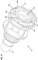
Figure 9 is a perspective view of an inner member of the male aseptic coupling ofFigure 2 . -
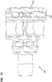
Figure 10 is a side view of the inner member of the male aseptic coupling ofFigure 9 . -
Figure 11 is a perspective view of the locking ring of the male aseptic coupling ofFigure 2 . -
Figure 12 is a side view of the locking ring of the male aseptic coupling ofFigure 11 . -
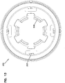
Figure 13 is an end view of the locking ring of the male aseptic coupling ofFigure 11 . -
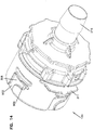
Figure 14 is a perspective view of a female aseptic coupling ofFigure 2 . -
Figure 15 is a side view of the female aseptic coupling ofFigure 14 . -
Figure 16 is a bottom view of the female aseptic coupling ofFigure 14 . -
Figure 17 is an end view of the female aseptic coupling ofFigure 14 . -
Figure 18 is a perspective view of an example clip. -
Figure 19 is an example method for connecting the aseptic coupling device. -
Figure 20 is a first perspective view of another aseptic coupling arrangement in a pre-coupled state. -
Figure 21 is a first exploded perspective view of the male coupling device of the arrangement ofFigure 20 . -
Figure 22 is a second exploded perspective view of the male coupling device of the arrangement ofFigure 20 . -
Figure 23 is a perspective view of another aseptic coupling arrangement having a coupler attached thereto. -
Figure 24 is a side view of the aseptic coupling arrangement ofFigure 23 . -
Figure 25 is a cross-sectional view of the aseptic coupling arrangement ofFigure 23 . -
Figure 26 is a first perspective view of the male and female aseptic coupling devices ofFigure 2 in an uncoupled state and with caps attached thereto. -
Figure 27 is a second perspective view of the male and female aseptic coupling devices ofFigure 2 in an uncoupled state and with caps attached thereto. -
Figure 28 is an end view of the cap of the male aseptic coupling device ofFigure 26 . -
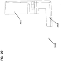
Figure 29 is a side view of the cap of the male aseptic coupling device ofFigure 26 . -
Figure 30 is a perspective view of the cap of the female aseptic coupling device ofFigure 26 . -
Figure 31 shows a side view of the cap of the female aseptic coupling device ofFigure 26 . -
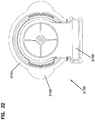
Figure 32 is an end view of the cap of the female aseptic coupling device ofFigure 26 . -
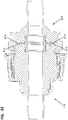
Figure 33 is another cross-sectional view of the aseptic coupling arrangement ofFigure 2 in a coupled state. -
Figure 34 is a side view of another example membrane for an aseptic coupling device. -
Figure 35 is a front view of the membrane ofFigure 34 . -
Figure 36 is a perspective view of the membrane ofFigure 34 . - Various embodiments will be described in detail with reference to the drawings, wherein like reference numerals represent like parts and assemblies throughout the several views. Reference to various embodiments does not limit the scope of the claims attached hereto. Additionally, any examples set forth in this specification are not intended to be limiting and merely set forth some of the many possible embodiments for the appended claims.
- As used herein, the term "sterilize" means a process of freeing, to a specified degree, a surface or volume from microorganisms. In example embodiments, the sterility of various components can be achieved using one or more sterilization techniques, including gamma irradiation, E-beam, ethylene oxide (EtO), and/or autoclave technologies.
- As used herein, the term "aseptic" refers to any process that maintains a sterilized surface or volume.
- As used herein, the term "fluid" means any substance that can be made to flow including, but is not limited to, liquids, gases, granular or powdered solids, mixtures or emulsions of two or more fluids, suspensions of solids within liquids or gases, etc.
- Referring now to
Figure 1 , anexample system 100 is shown.System 100 includes a first piece ofprocessing equipment 110 and a second piece ofprocessing equipment 120. In example embodiments,equipment equipment -
Equipment 110 includes afluid pathway 112 extending therefrom that is terminated by anaseptic coupling arrangement 121 including a firstaseptic coupling device 114. Likewise,equipment 120 includes afluid pathway 122 extending therefrom that is terminated by a secondaseptic coupling device 124 of theaseptic coupling arrangement 121. In example embodiments, the environment withinpathways aseptic coupling devices -
Aseptic coupling device 114 can be connected toaseptic coupling device 124. Onceaseptic coupling device 114 is connected toaseptic coupling device 124, a sterile fluid pathway is established betweenequipment 110 andequipment 120. Once the sterile fluid pathway is established, fluid can be transferred fromequipment 110 toequipment 120, or vice versa. - Referring now to
Figures 2-6 ,aseptic coupling devices aseptic coupling devices aseptic coupling devices - In the example shown,
aseptic coupling device 114 is a male coupling device, andaseptic coupling device 124 is a female coupling device. In the example shown, thedevices devices - In the example shown, the male
aseptic coupling device 114 includes aninner member 201, alocking ring 202, and amembrane 204. SeeFigures 9-13 . -
Inner member 201 defines afluid passage 502 throughaseptic coupling device 114.Inner member 201 is coupled to aportion 214. In the example shown,portion 214 is barbed so thatportion 214 can be connected to a fluid pathway (e.g., 112) such as a hose.Inner member 201 also includes acircular channel 504 that is formed to allowinner member 201 to be rotatably coupled to lockingring 202, as described below. -
Inner member 201 also defines achannel 304. SeeFigures 8-10 .Channel 304 is sized to receive a clip 212 (seeFigure 18 ) that is used to coupleaseptic coupling device 114 toaseptic coupling device 124. -
Membrane 204 is coupled, using, for example, an adhesive, to afront surface 802 ofinner member 201. As shown inFigure 9 , in example embodiments,front surface 802 includes anopening 804.Opening 804 allows fluid flow throughinner member 201.Front surface 802 forms a generally "D" shape and surrounds theopening 804. Anupper portion 809 of thefront surface 802 allowsmembrane 204 to extend beyond opening 804 so that asmembrane 204 is removed, the sterility ofopening 804 is maintained even ifmembranes Recess portions -
Inner member 201 also hasstops 313 formed adjacentfront surface 802. As described further below, stops 313 engage complementary structures on the mating device to define a coupled position. - In example embodiments, a
seal member 532 is positioned in awindow 531 formed by theinner member 201.Seal member 532 is positioned to engage acorresponding seal member 533 positioned in awindow 535 onaseptic coupling device 124 whenaseptic coupling devices membranes Figure 7 . - As shown in
Figures 2 ,4 ,5 ,8 ,16 , and17 ,membrane 204 extends through anopening 313 formed in thedevice 124. Ahandle portion 520 is coupled to anend 522 ofmembrane 204. In example embodiments, thehandle portion 520 includes one ormore attachment members 208, such as attachment members/apertures, that are positioned to engageattachment members 210 oncorresponding membrane 206 of theaseptic coupling device 124, as described further below. - Locking
ring 202 includes atab portion 506 that is positioned to be received inchannel 504 formed byinner member 201. SeeFigures 4 ,11 , and12 . This allows lockingring 202 to be spun in a direction 508 (seeFigure 5 ) to lockaseptic coupling device 114 toaseptic coupling device 124, as described below.Knurls 507 formed on thelocking ring 202 allow the user to easily grasp and rotate thelocking ring 202. - Locking
ring 202 also includes barbs 203 (seeFigures 4 and13 ) extending from and spaced about an inner periphery of lockingring 202. As shown inFigures 8-10 and described further below,barbs 203 are received in correspondingchannels 306 formed byaseptic coupling device 124 to coupleaseptic coupling device 114 thereto. In one embodiment, fourbarbs 203 are spaced radially about the inner periphery of lockingring 202. -
Aseptic coupling device 124 includes afront portion 530 configured to be coupled toaseptic coupling device 114, and abarbed portion 216 configured to be coupled to a fluid source. Afluid passage 503 is formed therethrough. -
Front portion 530 includeschannels 306 that extend from afront edge 307 offront portion 530. In the example show, eachchannel 306 includes aninlet portion 902 that extends generally axially, and a lockingportion 904 that extends generally radially. Theinlet portion 902 is sized to receive onebarb 203 of lockingring 202 ofaseptic coupling device 114. When thelocking ring 202 is rotated indirection 508,barb 203 extends into and is captured by lockingportion 904 ofchannel 306. In example embodiments, threechannels 306 are spaced axially aboutfront portion 530 to correspond tobarbs 203 of lockingring 202. -
Front portion 530 also definesslots 311 that are positioned to receiveclip 212.Barbs 1002 onclip 212 engage abottom surface 317 of device 124 (seeFigure 18 ). Rampedportions 1004 on eachside arm 1006 of theclip 212 extend radially inward throughslots 311 to engagechannel 304 onaseptic coupling device 114. The ramped surfaces of the rampedportions 1004 allow the device to ride along the rampedportions 1004 and pusharms 1006 away from one another to clear the rampedportions 1004. Upon clearance, the rampedportion 1004 move back into place withinchannel 304 to couple thedevices portions 1004 make a "clicking" noise as they clear and enter thechannel 304 to provide the user with audible and/or tactile feedback of a positive coupling. -
Membrane 206 is coupled to afront surface 910 ofaseptic coupling device 124. SeeFigure 17 . In examples,surface 910 is generally "D" shaped and surroundsopening 908. Similar tofront surface 802, anupper portion 909 offront surface 910 allowsmembrane 206 to extend beyond opening 908 so that asmembrane 206 is removed, the sterility ofopening 804 is maintained even ifmembranes - Adjacent
front surface 910 are formed stops 913. Thestops 913 engagestops 313 on thedevice 114 when the device is positioned in the coupled state. Thestops 313, 813 define the closes position that thedevices Figure 33 . In this manner, thestops 313, 813 define the amount of compression inseals devices stops - An end 554 of
membrane 206 includes ahandle portion 552 that includesattachment members 210 that are positioned to engageattachment members 208 on thecorresponding membrane 206 of theaseptic coupling device 124, as described further below. - Referring now to
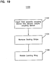
Figure 19 , anexample method 1100 for connectingaseptic coupling device 114 toaseptic coupling device 124 is shown. - First, at
operation 1102,front portion 530 ofaseptic coupling device 114 is inserted intoaseptic coupling device 124 alongcenterline 302. During insertion,barbs 203 are received ininlet portions 902 ofchannels 306. In addition,front portion 530 surroundsinner member 201. Whenfront portion 530 is fully inserted,barbs 1002 ofclip 212 are received inchannel 304 onaseptic coupling device 114. In this position (referred to as "pre-coupled"),aseptic coupling device 114 is coupled toaseptic coupling device 124. - Next, at
operation 1104, theattachment members 210 onhandle portion 552 ofmembrane 206 are connected toattachment members 208 onhandle portion 520 ofmembrane 204. Once connected, handleportions direction 559 is applied. Asmembranes direction 559,membranes ends aseptic coupling devices - Once
membranes ring 202 is rotated (stage 1106) indirection 508 so thatbarbs 203enter locking portions 904 ofchannels 306. Asbarbs 203 move along lockingportions 904,aseptic coupling device 114 is pulled slightly closer toaseptic coupling device 124 to compress theseal members passages aseptic coupling devices Figure 7 . As noted above, thestops seal members Figure 33 . - Referring now to
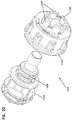
Figures 20-22 , an alternative embodiment of anaseptic coupling arrangement 1000 is shown. In the example shown,aseptic coupling device 114 is identical to that described above, and anaseptic coupling device 1124 is a male coupling that is similar toaseptic coupling device 124 describe above. - However,
aseptic coupling device 1124 includes a separateinner member 1102 andouter member 1104.Inner member 1102 is identical in shape toinner member 201 ofaseptic coupling device 114. This allows both components to be molded using the same machinery. -
Outer member 1104 includes atab portion 1106 with a plurality ofmembers 1107 that are positioned to be received in achannel 1108 formed byinner member 1102. This allowsouter member 1104 to be coupled toinner member 1102 and spin relative thereto. Other configurations are possible. - Referring now to
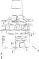
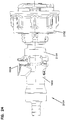
Figures 23-25 , another example embodiment of anaseptic coupling arrangement 2124 is shown. - In this example, an
aseptic coupling device 2152 includes atermination 2154 that is sized to be coupled to another coupling device, such as aquick disconnect coupler 1902. Examples of such couplers are described inU.S. Patent Nos. D357,307 ;D384,731 ;5,316,041 ; and5,494,074 . Other types of couplers can be used. - As shown, an
insert member 2156 is connected (e.g., by sonic welding) to thetermination 2154. Thecoupler 1902 is, in turn, connected to theinsert member 2156. - In the example shown, the
coupler 1902 includes avalving structure 1906, and theinsert member 2156 includes avalving structure 2158. Thesevalving structures coupler 1902 is connected to theinsert member 2156, so that fluid can flow therethrough. In such an example, theentire device 2152 can be sterilized prior to use. - When fluid flow is complete, a
latch 1908 of thecoupler 1902 can be actuated to disconnect thecoupler 1902 from theinsert member 2156 positioned between thetermination 2154 and thecoupler 1902. When disconnected,valving structure 1906 in coupler 1920 stops the flow of fluid through the coupler 1920, andvalving structure 2158 in theinsert member 2156 stops the flow of fluid through thedevice 2124. This can result in a disconnect that is also aseptic. Thecoupler 1902 can thereupon, in turn, be connected to other terminations as desired. - In other embodiments,
coupler 1902 can be connected toaseptic coupling device 114. In still further embodiments, bothaseptic coupling devices devices insert member 2156 can be coupled to the coupler 1920. Other configurations are possible. - Referring now to
Figures 26-32 , in example embodiments, acap 3100 can be connected toaseptic coupling device 124, and acap 3200 can be connected toaseptic coupling device 114. Thecaps membranes caps devices devices - As shown in
Figures 28 and29 , thecap 3200 includes abody 3202 that is concave to surround thefront surface 802 ofinner member 201 of thedevice 114.Tabs 3204 on thebody 3202 are received in thechannel 304 on theinner member 201 to releasably couple thecap 3200 to thedevice 114. Abottom member 3206 guides and protects a lower portion of themembrane 204. Thehandle portion 520 attached to themember 204 extends out of thebottom member 3206. - As shown in
Figures 30-32 , thecap 3100 includes abody 3102 that extends into thedevice 124.Slots 3113 on each side of thebody 3102 are positioned to engage rampedportions 1004 of the clip 212 (seeFigure 18 ) as thecap 3100 is inserted into thefront portion 530 of thedevice 124 to releasably hold thecap 3100 to thedevice 124.Tabs 3105 formed on thebody 3102 allow the user to grasp and remove thecap 3100 prior to use. Abottom member 3106 guides and protects a lower portion of themembrane 206. Thehandle portion 522 attached to themember 206 extends out of thebottom member 3106. - Referring now to
Figures 34-36 , anotherexample membrane 950 is shown. Themembrane 950 is similar in construction tomembranes aseptic coupling devices membrane 950 includes anenlarged portion 960 positioned at the end of themembrane 950 that is attached to thefront surfaces devices enlarged portion 960 is spherical in shape so that theportion 960 generally encompasses a larger part of thefront surface membrane 950 and thefront surfaces - In example embodiments, the aseptic coupling devices are made of a polymeric material. For example, in one embodiment, the aseptic coupling devices are made of polycarbonate and the seal members used therein are made of a silicone rubber. Other materials can be used.
- In some embodiments,
membranes membranes aseptic coupling devices 114 and 124). The vent is an expanded poly(tetrafluoroethylene) (ePTFE) membrane that will be bonded or welded onto the tag.Membranes aseptic coupling devices system 100 during sterilization. The pore size ofmembranes membranes - In another embodiment,
membranes - In other embodiments,
membranes membranes aseptic coupling devices 114 and 124). Tyvek is breathable in nature, so there is no need for an additional vent. Tyvek is a non-woven polyethylene membrane. - The various embodiments described above are provided by way of illustration only and should not be construed to limit the claims attached hereto. Those skilled in the art will readily recognize various modifications and changes that may be made without following the example embodiments and applications illustrated and described herein.
Claims (16)
- A system comprising:a first aseptic coupling device (114) comprisingan inner member (201) defining a first fluid passage (502) therethrough,a first seal member (532) coupled to a front surface (802) of the inner member,a first membrane (204) coupled to the front surface of the inner member to cover the first seal member, a clip (212), anda locking ring (202) positioned to rotate about the inner member; anda second aseptic coupling device (124) comprisinga main body defining a second fluid passage (503) therethrough,a front portion (530) coupled to the main body, the front portion defining a plurality of channels (306) therein,a second seal member (533) coupled to a front surface (910) of the main body,a second membrane (206) coupled to the front surface (910) of the main body to cover the second seal member, anda slot (311) defined in the main body sized to receive the clip (212),wherein the inner member is sized to be received in the front portion (530) of the second aseptic coupling device (124) to form a pre-coupled state in which the first aseptic coupling device is connected to the second aseptic coupling device but a sterile flow path has not yet been created because the first membrane and the second membrane are not yet removed,wherein, when the first membrane and the second membrane are removed, the first seal member engages the second seal member (533) of the second aseptic device, andwherein, upon turning of the locking ring, barbs (203) of the locking ring are received within the channels of the front portion to compress the first seal member and the second seal member to form a coupled state in which a sterile flow path is created between the first aseptic device and the second aseptic device,wherein the front portion is sized to receive the inner member of the first aseptic coupling device (114) so that the clip engages the first aseptic coupling device to form the pre-coupled state.
- The system of claim 1, wherein the front surface of the inner member forms a generally "D" shape.
- The system of claim 1, wherein:the inner member defines a first channel sized to receive a clip (212) of the second aseptic coupling device; andthe inner member receives the clip of the second aseptic coupling device to define the pre-coupled state.
- The system of claim 1, wherein the inner member includes a free end extending from the inner member, wherein the free end includes at least one snap configured to be coupled to the second membrane of the second aseptic coupling device.
- The system of claim 1, wherein the inner member (201) has stops (313) formed adjacent to the front surface (802) of the inner member and configured to engage complementary structures on the second coupling device to define the coupled state.
- The system of claim 6, wherein:a bottom surface of the second aseptic coupling device engages the clip to maintain the clip on the main body; andthe clip includes two side arms, each of the side arms extending radially inward through the slot to engage the first aseptic coupling device.
- The system of claim 6, wherein the front surface of the main body forms a generally "D" shape.
- The system of claim 6, wherein the inner member is keyed so that the inner member can be coupled to the first aseptic coupling device in only one orientation.
- The system of claim 6, wherein the inner member includes a free end extending from the inner member, wherein the free end includes at least one snap configured to be coupled to the first membrane of the first aseptic coupling device.
- The system of claim 6, wherein stops (913) are formed adjacent to the front surface (910) of the main body and configured to engage complementary stops on the first coupling device when positioned in the coupled state.
- A method for forming a sterile connection using the system of any preceding claim, the method comprising:inserting (1102) the first aseptic coupling device (114) into the second aseptic coupling device (124);removing (1104) the first membrane (204) from the first aseptic coupling device and the second membrane (206) from the second aseptic coupling device; androtating (1106) the locking ring (202) on the first aseptic coupling device to compress the first seal member (532) of the first aseptic coupling device with the second seal member (533) of the second aseptic coupling device to form the sterile fluid passageway.
- The method of claim 11, further comprising inserting the first aseptic coupling device into the second aseptic coupling device until the clip (212) on the second aseptic coupling device engages the first aseptic coupling device to form a pre-coupled state in which the first and the second aseptic coupling devices are connected but a sterile flow path has not yet been created because the first and second membrane are not yet removed.
- The method of claim 12, further comprising allowing barbs (203) on the second aseptic coupling device to be inserted into channels formed in the locking ring of the first aseptic coupling device.
- The method of claim 13, further comprising allowing the barbs to move within the channels as the locking ring is rotated to axially move the first and second aseptic coupling devices towards one another to a coupled state.
- The method of claim 13, further comprising allowing the first and second aseptic coupling devices to move from the pre-coupled state to a coupled state as the locking ring is rotated.
- The method of claim 13, further comprising adhering the first membrane to the front surface of the first aseptic coupling device forming a generally "D" shape.
Priority Applications (1)
| Application Number | Priority Date | Filing Date | Title |
|---|---|---|---|
| EP19214843.5A EP3696459B1 (en) | 2009-03-16 | 2010-03-15 | Aseptic coupling devices |
Applications Claiming Priority (2)
| Application Number | Priority Date | Filing Date | Title |
|---|---|---|---|
| US16060309P | 2009-03-16 | 2009-03-16 | |
| PCT/US2010/027311 WO2010107695A1 (en) | 2009-03-16 | 2010-03-15 | Aseptic coupling devices |
Related Child Applications (1)
| Application Number | Title | Priority Date | Filing Date |
|---|---|---|---|
| EP19214843.5A Division EP3696459B1 (en) | 2009-03-16 | 2010-03-15 | Aseptic coupling devices |
Publications (2)
| Publication Number | Publication Date |
|---|---|
| EP2409067A1 EP2409067A1 (en) | 2012-01-25 |
| EP2409067B1 true EP2409067B1 (en) | 2019-12-11 |
Family
ID=42313477
Family Applications (2)
| Application Number | Title | Priority Date | Filing Date |
|---|---|---|---|
| EP19214843.5A Active EP3696459B1 (en) | 2009-03-16 | 2010-03-15 | Aseptic coupling devices |
| EP10709364.3A Active EP2409067B1 (en) | 2009-03-16 | 2010-03-15 | Aseptic coupling devices |
Family Applications Before (1)
| Application Number | Title | Priority Date | Filing Date |
|---|---|---|---|
| EP19214843.5A Active EP3696459B1 (en) | 2009-03-16 | 2010-03-15 | Aseptic coupling devices |
Country Status (4)
| Country | Link |
|---|---|
| US (6) | US8491016B2 (en) |
| EP (2) | EP3696459B1 (en) |
| CN (1) | CN102405369B (en) |
| WO (1) | WO2010107695A1 (en) |
Cited By (1)
| Publication number | Priority date | Publication date | Assignee | Title |
|---|---|---|---|---|
| EP4628143A1 (en) * | 2024-04-05 | 2025-10-08 | Sartorius Stedim Fmt Sas | Aseptic connector arrangement with inner plug, and fluid connection system with clip assembly to unlock retracted open position of two plugs |
Families Citing this family (64)
| Publication number | Priority date | Publication date | Assignee | Title |
|---|---|---|---|---|
| EP3696459B1 (en) * | 2009-03-16 | 2023-09-20 | Colder Products Company | Aseptic coupling devices |
| US9597475B2 (en) * | 2011-07-15 | 2017-03-21 | Jack C McPhearson | Fast connect device for oxygen humidity bottles and other medical containers |
| US9433725B2 (en) | 2011-12-23 | 2016-09-06 | Alcon Research, Ltd. | Combined coaxial and bimanual irrigation/aspiration apparatus |
| EP3342450B1 (en) * | 2012-02-15 | 2021-12-15 | Colder Products Company | Aseptic coupling devices |
| WO2013147688A1 (en) * | 2012-03-27 | 2013-10-03 | Ge Healthcare Bio-Sciences Ab | Aseptic connector |
| US9364653B2 (en) * | 2012-04-27 | 2016-06-14 | Colder Products Company | Aseptic coupling devices |
| US20140093952A1 (en) * | 2012-10-02 | 2014-04-03 | David Serway | Bioreactor Tangential Flow Perfusion Filter System |
| US10711238B2 (en) * | 2012-10-02 | 2020-07-14 | Repligen Corporation | Method for proliferation of cells within a bioreactor using a disposable pumphead and filter assembly |
| GB2537563B (en) * | 2013-02-18 | 2017-09-13 | Salisbury Nhs Found Trust | Releasable connection for a tube |
| ES2708357T3 (en) | 2013-06-06 | 2019-04-09 | Novartis Ag | Irrigation device / aspiration transformer |
| FR3007816B1 (en) | 2013-06-28 | 2016-02-05 | Sartorius Stedim Biotech | ASEXUE FLUID CONNECTOR WITH COLLAR AND PROTECTION. |
| DE102013214068A1 (en) * | 2013-07-17 | 2015-01-22 | Parker Hannifin Manufacturing Germany GmbH & Co. KG | Device for creating a fluid connection |
| US9770581B2 (en) * | 2013-07-23 | 2017-09-26 | Colder Products Company | Aseptic coupling devices |
| ES2956015T3 (en) | 2013-11-06 | 2023-12-11 | Becton Dickinson & Co Ltd | System for closed fluid transfer with a locking member |
| JP6555826B2 (en) | 2013-11-07 | 2019-08-07 | ジーイー・ヘルスケア・バイオサイエンス・アクチボラグ | Aseptic connector |
| US20150260325A1 (en) * | 2014-03-14 | 2015-09-17 | Colder Products Company | Genderless Coupling Devices |
| US9752714B2 (en) | 2014-03-28 | 2017-09-05 | Eldon James Corp. | Releasable valved coupler |
| US9346578B2 (en) | 2014-05-30 | 2016-05-24 | Finesse Solutions, Inc. | Aseptic connectors for bio-processing containers |
| SG11201610017SA (en) | 2014-05-30 | 2016-12-29 | Finesse Solutions Inc | Aseptic connectors for bio-processing containers |
| US9851037B2 (en) | 2014-08-20 | 2017-12-26 | Nordson Corporation | Fluid connector and method for making sealed fluid connections |
| US9878144B2 (en) | 2014-10-14 | 2018-01-30 | Wilmarc Holdings, Llc | Connector system |
| JP6486498B2 (en) * | 2015-01-30 | 2019-03-20 | イー・エム・デイー・ミリポア・コーポレイシヨン | Fluid transfer device, system and method |
| US10022532B2 (en) * | 2015-04-20 | 2018-07-17 | Colder Products Company | Single use aseptic fluid couplings |
| US10350400B2 (en) | 2015-09-20 | 2019-07-16 | Erbi Biosystems, Inc. | Apparatus and methods for aseptic fluid interconnects |
| WO2017062859A1 (en) | 2015-10-08 | 2017-04-13 | Colder Products Company | Reusable aseptic fluid couplings |
| WO2017127579A1 (en) | 2016-01-19 | 2017-07-27 | Wilmarc Holdings, Llc | Connector system for releasably connecting fluid conduits |
| FR3047890B1 (en) * | 2016-02-22 | 2021-04-30 | Laurent Fumex | DEVICE FOR THE STERILE COUPLING OF A PERCUTANE SURGICAL INSTRUMENT AND A TRAINING TOOL AND METHOD FOR PERFORMING SUCH COUPLING |
| US10247342B2 (en) * | 2016-03-30 | 2019-04-02 | Pall Corporation | Connector assemblies, fluid systems including connector assemblies, and procedures for making fluid connections |
| CN109196264B (en) * | 2016-06-01 | 2022-01-25 | J·谢瓦利茨 | Device for aseptically connecting large-diameter pipelines |
| US10350401B2 (en) | 2017-03-08 | 2019-07-16 | Wilmarc Holdings, Llc | Catch assembly for releasably connecting fluid conduits |
| US11359172B2 (en) * | 2017-08-09 | 2022-06-14 | Sartorius Stedim Biotech Gmbh | Upstream and downstream processing within single-use containers |
| US11633584B2 (en) * | 2017-09-20 | 2023-04-25 | Miltenyi Biotec Gmbh | Sterile connector |
| WO2019079169A1 (en) * | 2017-10-16 | 2019-04-25 | Becton, Dickinson And Company | Connector for aseptic transfer of fluid |
| WO2019102622A1 (en) * | 2017-11-27 | 2019-05-31 | 株式会社Ihi | Connector |
| CN107883089B (en) * | 2017-12-19 | 2020-11-06 | 新沂阿凡达智能科技有限公司 | Connecting piece of British system catheter of low-pressure fluid conveying system |
| GB201808826D0 (en) * | 2018-05-30 | 2018-07-11 | Ge Healthcare Bio Sciences Ab | Connector for aseptic connection, and method for connecting and disconnecting such connectors |
| WO2020124245A1 (en) | 2018-12-20 | 2020-06-25 | Centre For Commercialization Of Regenerative Medicine | Systems and methods for a reusable, aseptic connector |
| CN109999333B (en) * | 2019-04-24 | 2024-05-10 | 华道(上海)生物医药有限公司 | Sterile butt joint device |
| KR102879867B1 (en) * | 2019-08-27 | 2025-11-04 | 콜더 프로덕츠 컴패니 | Disposable genderless sterile fluid coupling |
| EP4084854A4 (en) | 2019-12-31 | 2023-04-19 | Colder Products Company | ASEPTIC FLUID COUPLINGS |
| US11415255B1 (en) * | 2020-03-31 | 2022-08-16 | Colder Products Company | Aseptic fluid couplings |
| CN115768512A (en) | 2020-06-11 | 2023-03-07 | 考尔得产品公司 | Disposable breakaway fluid coupling |
| CN115734799A (en) | 2020-06-29 | 2023-03-03 | 考尔得产品公司 | Sterile fluid coupling |
| US11555567B2 (en) | 2020-06-30 | 2023-01-17 | Wilmarc Holdings, Llc | Sanitary fitting |
| WO2022047023A1 (en) * | 2020-08-27 | 2022-03-03 | Colder Products Company | Fluid couplings |
| US11661327B2 (en) | 2020-12-16 | 2023-05-30 | Fresh Blends Ltd. | Smart inventory management system for a dispensing and blend-in-cup beverage platform |
| FR3117569B1 (en) * | 2020-12-16 | 2022-11-25 | Parker Hannifin Emea Sarl | Device for aseptic connection of a tube |
| JP7763270B2 (en) * | 2021-05-27 | 2025-10-31 | インテグリス・インコーポレーテッド | Aseptic coupling assembly and method of aseptic coupling |
| US11739872B2 (en) | 2021-06-17 | 2023-08-29 | Colder Products Company | Aseptic fluid couplings |
| US12680639B2 (en) | 2021-07-01 | 2026-07-14 | Wilmarc Holdings, Llc | Genderless aseptic connector |
| WO2023027633A2 (en) | 2021-08-26 | 2023-03-02 | Agency For Science, Technology And Research | Connector component and connector system |
| EP4419186A4 (en) * | 2021-10-18 | 2025-04-09 | Colder Products Company | Fluid couplings |
| GB2620433B (en) * | 2022-07-08 | 2026-05-20 | Watson Marlow Ltd | Aseptic connector |
| GB2620436B (en) * | 2022-07-08 | 2024-12-04 | Watson Marlow Ltd | Aseptic connector |
| CN115154885B (en) * | 2022-08-15 | 2024-05-07 | 无锡耐思生命科技股份有限公司 | Aseptic connection piece and aseptic connection device |
| US12123526B2 (en) | 2022-09-12 | 2024-10-22 | Avantor Fluid Handling, Llc | Aseptic connect and disconnect coupler |
| US20240110142A1 (en) * | 2022-09-30 | 2024-04-04 | Life Technologies Corporation | Aseptic cell culture system and methods of use |
| CN116255516A (en) * | 2023-02-20 | 2023-06-13 | 上海乐纯生物技术股份有限公司 | Quick connector with anchor ear |
| EP4704958A1 (en) | 2023-04-25 | 2026-03-11 | WilMarc Holdings, LLC | Genderless aseptic connector |
| FR3148277B1 (en) * | 2023-04-28 | 2025-03-14 | Parker Hannifin Emea Sarl | Device for aseptic connection of a tube |
| WO2024258773A2 (en) * | 2023-06-12 | 2024-12-19 | Colder Products Company | Fluid handling couplings |
| US12601436B2 (en) | 2023-10-30 | 2026-04-14 | Wilmarc Holdings, Llc | Genderless aseptic connector |
| CN117803785A (en) * | 2023-12-18 | 2024-04-02 | 华道(上海)生物医药有限公司 | Sterile docking device and method of use |
| FR3161010B1 (en) * | 2024-04-04 | 2026-04-24 | Parker Hannifin Emea Sarl | Aseptic tube connection device comprising a protective membrane |
Family Cites Families (56)
| Publication number | Priority date | Publication date | Assignee | Title |
|---|---|---|---|---|
| US913144A (en) * | 1907-10-10 | 1909-02-23 | George James | Detachable pipe or hose coupling. |
| US1913144A (en) | 1928-07-18 | 1933-06-06 | Delco Prod Corp | Charge forming device |
| US1947593A (en) * | 1931-04-14 | 1934-02-20 | Peter J Hamilton | Hose coupling |
| US2419702A (en) * | 1944-08-05 | 1947-04-29 | Frederick A Barnes | Quick detachable coupling |
| US2868563A (en) * | 1956-06-05 | 1959-01-13 | Wayne L Wood | Fluid line coupling device |
| US3758137A (en) * | 1971-11-03 | 1973-09-11 | Parker Hannifin Corp | Quick disconnect coupling |
| US3831984A (en) * | 1971-11-08 | 1974-08-27 | Parker Hannifin Corp | Quick disconnect coupling |
| US3909910A (en) * | 1973-03-29 | 1975-10-07 | Union Carbide Corp | Method of joining the ends of two conduits together in a sterile manner |
| US4022205A (en) * | 1973-11-05 | 1977-05-10 | Tenczar Francis J | Fluid connectors |
| US3900223A (en) | 1974-01-23 | 1975-08-19 | Sundstrand Corp | Pipe coupling |
| US4022496A (en) | 1975-03-31 | 1977-05-10 | Aeroquip Corporation | Frangible diaphragm refrigeration coupling |
| US4019512A (en) * | 1975-12-04 | 1977-04-26 | Tenczar Francis J | Adhesively activated sterile connector |
| US4187846A (en) * | 1978-06-22 | 1980-02-12 | Union Carbide Corporation | Sterile connectors |
| EP0065369A3 (en) * | 1981-05-15 | 1985-12-18 | Corning Limited | Coupling |
| US4418945A (en) * | 1981-06-08 | 1983-12-06 | International Business Machines Corporation | Sterile connectors |
| NL8300386A (en) * | 1983-02-02 | 1984-09-03 | Steritech Bv | STERILE DEVICE CONNECTING TWO ROOMS. |
| US4673400A (en) * | 1986-02-10 | 1987-06-16 | Martin Ivan W | Aseptic connector assembly for conduits for sterile fluids |
| US4738401A (en) * | 1987-02-24 | 1988-04-19 | Spraying Systems Co. | Quick disconnect nozzle assembly with twist-on spray tip |
| US4886303A (en) * | 1988-07-11 | 1989-12-12 | J. M. Huber Corporation | Coupling with improved elastomeric face seal |
| US4951326A (en) * | 1990-02-06 | 1990-08-28 | Caretaker Systems, Inc. | Return fitting with releasable cap |
| US5316351A (en) * | 1992-08-06 | 1994-05-31 | Precision General, Inc. | Hose swivel |
| US5810398A (en) * | 1992-10-02 | 1998-09-22 | Pall Corporation | Fluid delivery systems and methods and assemblies for making connections |
| USD357307S (en) | 1992-10-27 | 1995-04-11 | Colder Products Company | Quick connection coupling valve assembly |
| US5316041A (en) | 1992-10-27 | 1994-05-31 | Colder Product Company | Quick connection coupling valve assembly |
| US5348570A (en) * | 1993-04-05 | 1994-09-20 | Rockwell International Corporation | Axle housing breather |
| US5395351A (en) * | 1993-09-29 | 1995-03-07 | Baxter International Inc. | Self-valving connector and interface system and a method of using same |
| USD384731S (en) | 1994-10-04 | 1997-10-07 | Colder Products Company | Quick connection coupling valve assembly |
| US5492147A (en) | 1995-01-17 | 1996-02-20 | Aeroquip Corporation | Dry break coupling |
| US6050613A (en) * | 1996-04-01 | 2000-04-18 | Continental Industries, Inc. | Combined plastic pipe coupler and end plug |
| EP1716885A3 (en) * | 1997-05-09 | 2006-11-15 | Pall Corporation | Connector assemblies, fluid systems, and methods for making a connection |
| US6585695B1 (en) * | 1998-10-29 | 2003-07-01 | Minimed Inc. | Reservoir connector |
| US20020173748A1 (en) * | 1998-10-29 | 2002-11-21 | Mcconnell Susan | Reservoir connector |
| US6679529B2 (en) * | 2001-08-06 | 2004-01-20 | Theodore D. Johnson | Connection system |
| JP3972665B2 (en) * | 2002-01-25 | 2007-09-05 | 株式会社ジェイ・エム・エス | Aseptic connector system |
| US6911025B2 (en) * | 2002-01-25 | 2005-06-28 | Jms Co., Ltd. | Connector system for sterile connection |
| GB0229870D0 (en) * | 2002-12-21 | 2003-01-29 | Intersurgical Ltd | Improvements relating to closure devices |
| US7488311B2 (en) * | 2004-12-23 | 2009-02-10 | Hospira, Inc. | Port closure system for intravenous fluid container |
| US7717897B2 (en) * | 2004-12-23 | 2010-05-18 | Hospira, Inc. | Medical fluid container with concave side weld |
| DE102005020648A1 (en) | 2005-05-03 | 2006-11-16 | Sartorius Ag | Connector, connector system and use |
| DE102005020647B4 (en) * | 2005-05-03 | 2013-11-28 | Sartorius Stedim Biotech Gmbh | Connector, connector system and method of sterile connection |
| US7695022B2 (en) * | 2005-06-30 | 2010-04-13 | Eaton Corporation | Fluid coupling cap |
| SI3045182T1 (en) | 2005-11-14 | 2018-08-31 | Teva Pharmaceuticals International Gmbh | Antagonist antibodies directed against calcitonin gene-related peptide for treating cluster headache |
| US9895526B2 (en) * | 2006-03-08 | 2018-02-20 | Ivaxis, Llc | Anti-contamination cover for fluid connections |
| US8226609B2 (en) * | 2007-06-25 | 2012-07-24 | Bioquiddity, Inc. | Fluid dispenser with additive sub-system |
| WO2009111901A2 (en) * | 2008-03-14 | 2009-09-17 | Rm Beteiligungs Ag | Method for filling a plastic container having a container neck and applying a capsule thereon |
| BRPI0909316B1 (en) * | 2008-03-25 | 2021-08-10 | Saint-Gobain Performance Plastics Corporation | CONNECTION SET AND STERILE CONNECTION FORMATION METHOD |
| EP3696459B1 (en) * | 2009-03-16 | 2023-09-20 | Colder Products Company | Aseptic coupling devices |
| US10166381B2 (en) * | 2011-05-23 | 2019-01-01 | Excelsior Medical Corporation | Antiseptic cap |
| EP3342450B1 (en) * | 2012-02-15 | 2021-12-15 | Colder Products Company | Aseptic coupling devices |
| ES2676825T3 (en) * | 2012-02-15 | 2018-07-25 | Np Medical Inc. | Multipurpose protective cover for use in a medical device |
| US9364653B2 (en) * | 2012-04-27 | 2016-06-14 | Colder Products Company | Aseptic coupling devices |
| AU2015252808B2 (en) * | 2014-05-02 | 2019-02-21 | Excelsior Medical Corporation | Strip package for antiseptic cap |
| US9851037B2 (en) * | 2014-08-20 | 2017-12-26 | Nordson Corporation | Fluid connector and method for making sealed fluid connections |
| TWI691344B (en) * | 2015-01-08 | 2020-04-21 | 瑞典商梅特諾瓦有限公司 | Method and device for aseptic connection |
| US10247342B2 (en) * | 2016-03-30 | 2019-04-02 | Pall Corporation | Connector assemblies, fluid systems including connector assemblies, and procedures for making fluid connections |
| EP3612266B1 (en) * | 2017-04-21 | 2023-12-20 | Becton, Dickinson And Company | Connector cap |
-
2010
- 2010-03-15 EP EP19214843.5A patent/EP3696459B1/en active Active
- 2010-03-15 US US12/724,125 patent/US8491016B2/en active Active
- 2010-03-15 EP EP10709364.3A patent/EP2409067B1/en active Active
- 2010-03-15 CN CN201080017233.2A patent/CN102405369B/en active Active
- 2010-03-15 WO PCT/US2010/027311 patent/WO2010107695A1/en not_active Ceased
-
2012
- 2012-12-04 US US13/693,720 patent/US9027968B2/en active Active
-
2015
- 2015-04-10 US US14/683,662 patent/US9879808B2/en active Active
-
2017
- 2017-02-01 US US15/421,836 patent/US10871250B2/en active Active
-
2020
- 2020-12-04 US US17/111,921 patent/US12060960B2/en active Active
-
2024
- 2024-08-08 US US18/798,200 patent/US12560263B2/en active Active
Non-Patent Citations (1)
| Title |
|---|
| None * |
Cited By (2)
| Publication number | Priority date | Publication date | Assignee | Title |
|---|---|---|---|---|
| EP4628143A1 (en) * | 2024-04-05 | 2025-10-08 | Sartorius Stedim Fmt Sas | Aseptic connector arrangement with inner plug, and fluid connection system with clip assembly to unlock retracted open position of two plugs |
| WO2025209865A1 (en) * | 2024-04-05 | 2025-10-09 | Sartorius Stedim Fmt | Aseptic connector arrangement with inner plug, and fluid connection system with clip assembly to unlock retracted open position of two plugs |
Also Published As
| Publication number | Publication date |
|---|---|
| CN102405369A (en) | 2012-04-04 |
| US8491016B2 (en) | 2013-07-23 |
| US20150323114A1 (en) | 2015-11-12 |
| US10871250B2 (en) | 2020-12-22 |
| CN102405369B (en) | 2016-04-20 |
| EP2409067A1 (en) | 2012-01-25 |
| US20250043894A1 (en) | 2025-02-06 |
| US12060960B2 (en) | 2024-08-13 |
| EP3696459B1 (en) | 2023-09-20 |
| WO2010107695A1 (en) | 2010-09-23 |
| US9027968B2 (en) | 2015-05-12 |
| US20130099489A1 (en) | 2013-04-25 |
| US9879808B2 (en) | 2018-01-30 |
| US20170143953A1 (en) | 2017-05-25 |
| US20210095802A1 (en) | 2021-04-01 |
| EP3696459A1 (en) | 2020-08-19 |
| US20100230950A1 (en) | 2010-09-16 |
| US12560263B2 (en) | 2026-02-24 |
Similar Documents
| Publication | Publication Date | Title |
|---|---|---|
| EP3696459B1 (en) | Aseptic coupling devices | |
| US12042621B2 (en) | Aseptic coupling devices | |
| US11614188B2 (en) | Aseptic coupling devices | |
| US10213592B2 (en) | Aseptic coupling devices |
Legal Events
| Date | Code | Title | Description |
|---|---|---|---|
| PUAI | Public reference made under article 153(3) epc to a published international application that has entered the european phase |
Free format text: ORIGINAL CODE: 0009012 |
|
| 17P | Request for examination filed |
Effective date: 20111014 |
|
| AK | Designated contracting states |
Kind code of ref document: A1 Designated state(s): AT BE BG CH CY CZ DE DK EE ES FI FR GB GR HR HU IE IS IT LI LT LU LV MC MK MT NL NO PL PT RO SE SI SK SM TR |
|
| DAX | Request for extension of the european patent (deleted) | ||
| STAA | Information on the status of an ep patent application or granted ep patent |
Free format text: STATUS: EXAMINATION IS IN PROGRESS |
|
| 17Q | First examination report despatched |
Effective date: 20180605 |
|
| GRAP | Despatch of communication of intention to grant a patent |
Free format text: ORIGINAL CODE: EPIDOSNIGR1 |
|
| STAA | Information on the status of an ep patent application or granted ep patent |
Free format text: STATUS: GRANT OF PATENT IS INTENDED |
|
| INTG | Intention to grant announced |
Effective date: 20190624 |
|
| GRAS | Grant fee paid |
Free format text: ORIGINAL CODE: EPIDOSNIGR3 |
|
| GRAA | (expected) grant |
Free format text: ORIGINAL CODE: 0009210 |
|
| STAA | Information on the status of an ep patent application or granted ep patent |
Free format text: STATUS: THE PATENT HAS BEEN GRANTED |
|
| AK | Designated contracting states |
Kind code of ref document: B1 Designated state(s): AT BE BG CH CY CZ DE DK EE ES FI FR GB GR HR HU IE IS IT LI LT LU LV MC MK MT NL NO PL PT RO SE SI SK SM TR |
|
| REG | Reference to a national code |
Ref country code: GB Ref legal event code: FG4D |
|
| REG | Reference to a national code |
Ref country code: CH Ref legal event code: EP |
|
| REG | Reference to a national code |
Ref country code: AT Ref legal event code: REF Ref document number: 1212541 Country of ref document: AT Kind code of ref document: T Effective date: 20191215 |
|
| REG | Reference to a national code |
Ref country code: DE Ref legal event code: R096 Ref document number: 602010062323 Country of ref document: DE |
|
| REG | Reference to a national code |
Ref country code: IE Ref legal event code: FG4D |
|
| REG | Reference to a national code |
Ref country code: NL Ref legal event code: MP Effective date: 20191211 |
|
| REG | Reference to a national code |
Ref country code: LT Ref legal event code: MG4D |
|
| PG25 | Lapsed in a contracting state [announced via postgrant information from national office to epo] |
Ref country code: GR Free format text: LAPSE BECAUSE OF FAILURE TO SUBMIT A TRANSLATION OF THE DESCRIPTION OR TO PAY THE FEE WITHIN THE PRESCRIBED TIME-LIMIT Effective date: 20200312 Ref country code: LT Free format text: LAPSE BECAUSE OF FAILURE TO SUBMIT A TRANSLATION OF THE DESCRIPTION OR TO PAY THE FEE WITHIN THE PRESCRIBED TIME-LIMIT Effective date: 20191211 Ref country code: FI Free format text: LAPSE BECAUSE OF FAILURE TO SUBMIT A TRANSLATION OF THE DESCRIPTION OR TO PAY THE FEE WITHIN THE PRESCRIBED TIME-LIMIT Effective date: 20191211 Ref country code: BG Free format text: LAPSE BECAUSE OF FAILURE TO SUBMIT A TRANSLATION OF THE DESCRIPTION OR TO PAY THE FEE WITHIN THE PRESCRIBED TIME-LIMIT Effective date: 20200311 Ref country code: LV Free format text: LAPSE BECAUSE OF FAILURE TO SUBMIT A TRANSLATION OF THE DESCRIPTION OR TO PAY THE FEE WITHIN THE PRESCRIBED TIME-LIMIT Effective date: 20191211 Ref country code: SE Free format text: LAPSE BECAUSE OF FAILURE TO SUBMIT A TRANSLATION OF THE DESCRIPTION OR TO PAY THE FEE WITHIN THE PRESCRIBED TIME-LIMIT Effective date: 20191211 Ref country code: NO Free format text: LAPSE BECAUSE OF FAILURE TO SUBMIT A TRANSLATION OF THE DESCRIPTION OR TO PAY THE FEE WITHIN THE PRESCRIBED TIME-LIMIT Effective date: 20200311 Ref country code: ES Free format text: LAPSE BECAUSE OF FAILURE TO SUBMIT A TRANSLATION OF THE DESCRIPTION OR TO PAY THE FEE WITHIN THE PRESCRIBED TIME-LIMIT Effective date: 20191211 |
|
| PG25 | Lapsed in a contracting state [announced via postgrant information from national office to epo] |
Ref country code: HR Free format text: LAPSE BECAUSE OF FAILURE TO SUBMIT A TRANSLATION OF THE DESCRIPTION OR TO PAY THE FEE WITHIN THE PRESCRIBED TIME-LIMIT Effective date: 20191211 |
|
| PG25 | Lapsed in a contracting state [announced via postgrant information from national office to epo] |
Ref country code: NL Free format text: LAPSE BECAUSE OF FAILURE TO SUBMIT A TRANSLATION OF THE DESCRIPTION OR TO PAY THE FEE WITHIN THE PRESCRIBED TIME-LIMIT Effective date: 20191211 Ref country code: EE Free format text: LAPSE BECAUSE OF FAILURE TO SUBMIT A TRANSLATION OF THE DESCRIPTION OR TO PAY THE FEE WITHIN THE PRESCRIBED TIME-LIMIT Effective date: 20191211 Ref country code: PT Free format text: LAPSE BECAUSE OF FAILURE TO SUBMIT A TRANSLATION OF THE DESCRIPTION OR TO PAY THE FEE WITHIN THE PRESCRIBED TIME-LIMIT Effective date: 20200506 Ref country code: RO Free format text: LAPSE BECAUSE OF FAILURE TO SUBMIT A TRANSLATION OF THE DESCRIPTION OR TO PAY THE FEE WITHIN THE PRESCRIBED TIME-LIMIT Effective date: 20191211 Ref country code: CZ Free format text: LAPSE BECAUSE OF FAILURE TO SUBMIT A TRANSLATION OF THE DESCRIPTION OR TO PAY THE FEE WITHIN THE PRESCRIBED TIME-LIMIT Effective date: 20191211 |
|
| PG25 | Lapsed in a contracting state [announced via postgrant information from national office to epo] |
Ref country code: SM Free format text: LAPSE BECAUSE OF FAILURE TO SUBMIT A TRANSLATION OF THE DESCRIPTION OR TO PAY THE FEE WITHIN THE PRESCRIBED TIME-LIMIT Effective date: 20191211 Ref country code: SK Free format text: LAPSE BECAUSE OF FAILURE TO SUBMIT A TRANSLATION OF THE DESCRIPTION OR TO PAY THE FEE WITHIN THE PRESCRIBED TIME-LIMIT Effective date: 20191211 Ref country code: IS Free format text: LAPSE BECAUSE OF FAILURE TO SUBMIT A TRANSLATION OF THE DESCRIPTION OR TO PAY THE FEE WITHIN THE PRESCRIBED TIME-LIMIT Effective date: 20200411 |
|
| REG | Reference to a national code |
Ref country code: DE Ref legal event code: R097 Ref document number: 602010062323 Country of ref document: DE |
|
| REG | Reference to a national code |
Ref country code: AT Ref legal event code: MK05 Ref document number: 1212541 Country of ref document: AT Kind code of ref document: T Effective date: 20191211 |
|
| PLBE | No opposition filed within time limit |
Free format text: ORIGINAL CODE: 0009261 |
|
| STAA | Information on the status of an ep patent application or granted ep patent |
Free format text: STATUS: NO OPPOSITION FILED WITHIN TIME LIMIT |
|
| PG25 | Lapsed in a contracting state [announced via postgrant information from national office to epo] |
Ref country code: DK Free format text: LAPSE BECAUSE OF FAILURE TO SUBMIT A TRANSLATION OF THE DESCRIPTION OR TO PAY THE FEE WITHIN THE PRESCRIBED TIME-LIMIT Effective date: 20191211 Ref country code: MC Free format text: LAPSE BECAUSE OF FAILURE TO SUBMIT A TRANSLATION OF THE DESCRIPTION OR TO PAY THE FEE WITHIN THE PRESCRIBED TIME-LIMIT Effective date: 20191211 |
|
| REG | Reference to a national code |
Ref country code: CH Ref legal event code: PL |
|
| 26N | No opposition filed |
Effective date: 20200914 |
|
| PG25 | Lapsed in a contracting state [announced via postgrant information from national office to epo] |
Ref country code: AT Free format text: LAPSE BECAUSE OF FAILURE TO SUBMIT A TRANSLATION OF THE DESCRIPTION OR TO PAY THE FEE WITHIN THE PRESCRIBED TIME-LIMIT Effective date: 20191211 Ref country code: PL Free format text: LAPSE BECAUSE OF FAILURE TO SUBMIT A TRANSLATION OF THE DESCRIPTION OR TO PAY THE FEE WITHIN THE PRESCRIBED TIME-LIMIT Effective date: 20191211 Ref country code: SI Free format text: LAPSE BECAUSE OF FAILURE TO SUBMIT A TRANSLATION OF THE DESCRIPTION OR TO PAY THE FEE WITHIN THE PRESCRIBED TIME-LIMIT Effective date: 20191211 |
|
| REG | Reference to a national code |
Ref country code: BE Ref legal event code: MM Effective date: 20200331 |
|
| PG25 | Lapsed in a contracting state [announced via postgrant information from national office to epo] |
Ref country code: LU Free format text: LAPSE BECAUSE OF NON-PAYMENT OF DUE FEES Effective date: 20200315 |
|
| PG25 | Lapsed in a contracting state [announced via postgrant information from national office to epo] |
Ref country code: CH Free format text: LAPSE BECAUSE OF NON-PAYMENT OF DUE FEES Effective date: 20200331 Ref country code: IT Free format text: LAPSE BECAUSE OF FAILURE TO SUBMIT A TRANSLATION OF THE DESCRIPTION OR TO PAY THE FEE WITHIN THE PRESCRIBED TIME-LIMIT Effective date: 20191211 Ref country code: LI Free format text: LAPSE BECAUSE OF NON-PAYMENT OF DUE FEES Effective date: 20200331 |
|
| PG25 | Lapsed in a contracting state [announced via postgrant information from national office to epo] |
Ref country code: BE Free format text: LAPSE BECAUSE OF NON-PAYMENT OF DUE FEES Effective date: 20200331 |
|
| PG25 | Lapsed in a contracting state [announced via postgrant information from national office to epo] |
Ref country code: TR Free format text: LAPSE BECAUSE OF FAILURE TO SUBMIT A TRANSLATION OF THE DESCRIPTION OR TO PAY THE FEE WITHIN THE PRESCRIBED TIME-LIMIT Effective date: 20191211 Ref country code: MT Free format text: LAPSE BECAUSE OF FAILURE TO SUBMIT A TRANSLATION OF THE DESCRIPTION OR TO PAY THE FEE WITHIN THE PRESCRIBED TIME-LIMIT Effective date: 20191211 Ref country code: CY Free format text: LAPSE BECAUSE OF FAILURE TO SUBMIT A TRANSLATION OF THE DESCRIPTION OR TO PAY THE FEE WITHIN THE PRESCRIBED TIME-LIMIT Effective date: 20191211 |
|
| PG25 | Lapsed in a contracting state [announced via postgrant information from national office to epo] |
Ref country code: MK Free format text: LAPSE BECAUSE OF FAILURE TO SUBMIT A TRANSLATION OF THE DESCRIPTION OR TO PAY THE FEE WITHIN THE PRESCRIBED TIME-LIMIT Effective date: 20191211 |
|
| P01 | Opt-out of the competence of the unified patent court (upc) registered |
Effective date: 20230425 |
|
| PGFP | Annual fee paid to national office [announced via postgrant information from national office to epo] |
Ref country code: GB Payment date: 20260319 Year of fee payment: 17 |
|
| PGFP | Annual fee paid to national office [announced via postgrant information from national office to epo] |
Ref country code: IE Payment date: 20260318 Year of fee payment: 17 Ref country code: DE Payment date: 20260320 Year of fee payment: 17 |
|
| PGFP | Annual fee paid to national office [announced via postgrant information from national office to epo] |
Ref country code: FR Payment date: 20260323 Year of fee payment: 17 |