EP2408053A2 - Assigning addresses to multiple cascade battery modules - Google Patents
Assigning addresses to multiple cascade battery modules Download PDFInfo
- Publication number
- EP2408053A2 EP2408053A2 EP20110174102 EP11174102A EP2408053A2 EP 2408053 A2 EP2408053 A2 EP 2408053A2 EP 20110174102 EP20110174102 EP 20110174102 EP 11174102 A EP11174102 A EP 11174102A EP 2408053 A2 EP2408053 A2 EP 2408053A2
- Authority
- EP
- European Patent Office
- Prior art keywords
- battery
- module
- battery module
- current
- switch
- Prior art date
- Legal status (The legal status is an assumption and is not a legal conclusion. Google has not performed a legal analysis and makes no representation as to the accuracy of the status listed.)
- Withdrawn
Links
Images


Classifications
-
- H—ELECTRICITY
- H01—ELECTRIC ELEMENTS
- H01M—PROCESSES OR MEANS, e.g. BATTERIES, FOR THE DIRECT CONVERSION OF CHEMICAL ENERGY INTO ELECTRICAL ENERGY
- H01M10/00—Secondary cells; Manufacture thereof
- H01M10/42—Methods or arrangements for servicing or maintenance of secondary cells or secondary half-cells
- H01M10/425—Structural combination with electronic components, e.g. electronic circuits integrated to the outside of the casing
-
- B—PERFORMING OPERATIONS; TRANSPORTING
- B60—VEHICLES IN GENERAL
- B60L—PROPULSION OF ELECTRICALLY-PROPELLED VEHICLES; SUPPLYING ELECTRIC POWER FOR AUXILIARY EQUIPMENT OF ELECTRICALLY-PROPELLED VEHICLES; ELECTRODYNAMIC BRAKE SYSTEMS FOR VEHICLES IN GENERAL; MAGNETIC SUSPENSION OR LEVITATION FOR VEHICLES; MONITORING OPERATING VARIABLES OF ELECTRICALLY-PROPELLED VEHICLES; ELECTRIC SAFETY DEVICES FOR ELECTRICALLY-PROPELLED VEHICLES
- B60L58/00—Methods or circuit arrangements for monitoring or controlling batteries or fuel cells, specially adapted for electric vehicles
- B60L58/10—Methods or circuit arrangements for monitoring or controlling batteries or fuel cells, specially adapted for electric vehicles for monitoring or controlling batteries
- B60L58/18—Methods or circuit arrangements for monitoring or controlling batteries or fuel cells, specially adapted for electric vehicles for monitoring or controlling batteries of two or more battery modules
- B60L58/21—Methods or circuit arrangements for monitoring or controlling batteries or fuel cells, specially adapted for electric vehicles for monitoring or controlling batteries of two or more battery modules having the same nominal voltage
-
- H—ELECTRICITY
- H01—ELECTRIC ELEMENTS
- H01M—PROCESSES OR MEANS, e.g. BATTERIES, FOR THE DIRECT CONVERSION OF CHEMICAL ENERGY INTO ELECTRICAL ENERGY
- H01M10/00—Secondary cells; Manufacture thereof
- H01M10/42—Methods or arrangements for servicing or maintenance of secondary cells or secondary half-cells
- H01M10/48—Accumulators combined with arrangements for measuring, testing or indicating the condition of cells, e.g. the level or density of the electrolyte
- H01M10/482—Accumulators combined with arrangements for measuring, testing or indicating the condition of cells, e.g. the level or density of the electrolyte for several batteries or cells simultaneously or sequentially
-
- H—ELECTRICITY
- H02—GENERATION; CONVERSION OR DISTRIBUTION OF ELECTRIC POWER
- H02J—ELECTRIC POWER NETWORKS; CIRCUIT ARRANGEMENTS OR SYSTEMS FOR SUPPLYING OR DISTRIBUTING ELECTRIC POWER; SYSTEMS FOR STORING ELECTRIC ENERGY
- H02J7/00—Circuit arrangements for charging or discharging batteries or for supplying loads from batteries
- H02J7/50—Circuit arrangements for charging or discharging batteries or for supplying loads from batteries acting upon multiple batteries simultaneously or sequentially
-
- H—ELECTRICITY
- H02—GENERATION; CONVERSION OR DISTRIBUTION OF ELECTRIC POWER
- H02J—ELECTRIC POWER NETWORKS; CIRCUIT ARRANGEMENTS OR SYSTEMS FOR SUPPLYING OR DISTRIBUTING ELECTRIC POWER; SYSTEMS FOR STORING ELECTRIC ENERGY
- H02J7/00—Circuit arrangements for charging or discharging batteries or for supplying loads from batteries
- H02J7/80—Circuit arrangements for charging or discharging batteries or for supplying loads from batteries including monitoring or indicating arrangements
-
- G—PHYSICS
- G01—MEASURING; TESTING
- G01R—MEASURING ELECTRIC VARIABLES; MEASURING MAGNETIC VARIABLES
- G01R31/00—Arrangements for testing electric properties; Arrangements for locating electric faults; Arrangements for electrical testing characterised by what is being tested not provided for elsewhere
- G01R31/005—Testing of electric installations on transport means
- G01R31/006—Testing of electric installations on transport means on road vehicles, e.g. automobiles or trucks
- G01R31/007—Testing of electric installations on transport means on road vehicles, e.g. automobiles or trucks using microprocessors or computers
-
- G—PHYSICS
- G01—MEASURING; TESTING
- G01R—MEASURING ELECTRIC VARIABLES; MEASURING MAGNETIC VARIABLES
- G01R31/00—Arrangements for testing electric properties; Arrangements for locating electric faults; Arrangements for electrical testing characterised by what is being tested not provided for elsewhere
- G01R31/36—Arrangements for testing, measuring or monitoring the electrical condition of accumulators or electric batteries, e.g. capacity or state of charge [SoC]
- G01R31/364—Battery terminal connectors with integrated measuring arrangements
-
- G—PHYSICS
- G01—MEASURING; TESTING
- G01R—MEASURING ELECTRIC VARIABLES; MEASURING MAGNETIC VARIABLES
- G01R31/00—Arrangements for testing electric properties; Arrangements for locating electric faults; Arrangements for electrical testing characterised by what is being tested not provided for elsewhere
- G01R31/36—Arrangements for testing, measuring or monitoring the electrical condition of accumulators or electric batteries, e.g. capacity or state of charge [SoC]
- G01R31/371—Arrangements for testing, measuring or monitoring the electrical condition of accumulators or electric batteries, e.g. capacity or state of charge [SoC] with remote indication, e.g. on external chargers
-
- G—PHYSICS
- G01—MEASURING; TESTING
- G01R—MEASURING ELECTRIC VARIABLES; MEASURING MAGNETIC VARIABLES
- G01R31/00—Arrangements for testing electric properties; Arrangements for locating electric faults; Arrangements for electrical testing characterised by what is being tested not provided for elsewhere
- G01R31/36—Arrangements for testing, measuring or monitoring the electrical condition of accumulators or electric batteries, e.g. capacity or state of charge [SoC]
- G01R31/396—Acquisition or processing of data for testing or for monitoring individual cells or groups of cells within a battery
-
- H—ELECTRICITY
- H01—ELECTRIC ELEMENTS
- H01M—PROCESSES OR MEANS, e.g. BATTERIES, FOR THE DIRECT CONVERSION OF CHEMICAL ENERGY INTO ELECTRICAL ENERGY
- H01M10/00—Secondary cells; Manufacture thereof
- H01M10/42—Methods or arrangements for servicing or maintenance of secondary cells or secondary half-cells
- H01M10/425—Structural combination with electronic components, e.g. electronic circuits integrated to the outside of the casing
- H01M2010/4278—Systems for data transfer from batteries, e.g. transfer of battery parameters to a controller, data transferred between battery controller and main controller
-
- Y—GENERAL TAGGING OF NEW TECHNOLOGICAL DEVELOPMENTS; GENERAL TAGGING OF CROSS-SECTIONAL TECHNOLOGIES SPANNING OVER SEVERAL SECTIONS OF THE IPC; TECHNICAL SUBJECTS COVERED BY FORMER USPC CROSS-REFERENCE ART COLLECTIONS [XRACs] AND DIGESTS
- Y02—TECHNOLOGIES OR APPLICATIONS FOR MITIGATION OR ADAPTATION AGAINST CLIMATE CHANGE
- Y02E—REDUCTION OF GREENHOUSE GAS [GHG] EMISSIONS, RELATED TO ENERGY GENERATION, TRANSMISSION OR DISTRIBUTION
- Y02E60/00—Enabling technologies; Technologies with a potential or indirect contribution to GHG emissions mitigation
- Y02E60/10—Energy storage using batteries
-
- Y—GENERAL TAGGING OF NEW TECHNOLOGICAL DEVELOPMENTS; GENERAL TAGGING OF CROSS-SECTIONAL TECHNOLOGIES SPANNING OVER SEVERAL SECTIONS OF THE IPC; TECHNICAL SUBJECTS COVERED BY FORMER USPC CROSS-REFERENCE ART COLLECTIONS [XRACs] AND DIGESTS
- Y02—TECHNOLOGIES OR APPLICATIONS FOR MITIGATION OR ADAPTATION AGAINST CLIMATE CHANGE
- Y02T—CLIMATE CHANGE MITIGATION TECHNOLOGIES RELATED TO TRANSPORTATION
- Y02T10/00—Road transport of goods or passengers
- Y02T10/60—Other road transportation technologies with climate change mitigation effect
- Y02T10/70—Energy storage systems for electromobility, e.g. batteries
Definitions
- Battery Management Systems typically include a plurality of battery modules coupled in cascade in order to provide relatively high energy for Electric Vehicles (EVs) and/or Hybrid Electric Vehicles (HEVs).
- Each battery module typically includes a plurality of battery cells and circuitry configured to monitor a status of the battery cells and to communicate the status to, e.g., a remote control unit.
- each battery module it is desirable for each battery module to be manufactured identically to each other battery module, providing savings in both manufacturing cost and the time to manufacture the modules. In operation, however, it may be desirable to individually address each battery module, e.g., in order to identify a particular battery module. It may also be desirable to assemble the plurality of battery modules into a battery management system without consideration of a relative position of each module in the system. Providing unique addresses at manufacturing can be done but adds time and cost to the manufacturing process. It may therefore be desirable to identify and assign unique addresses to battery modules after they have been assembled into a BMS.
- the apparatus may include a first battery module.
- the first battery module may include a switch configured to open or close a first current path from a first terminal of a battery to a second terminal of the battery when a second battery module is coupled to the first battery module; a current sensor configured to sense a current in a second current path, the second current path different from the first current path; and a local controller configured to control a state of the switch to open or close the switch, wherein closing the switch is configured to close the first current path, the local controller is further configured to detect the sensed current in the second current path, and the local controller is further configured to receive and store an identifier based at least in part on the current detected in the second current path.
- the method may include closing a switch in each battery module, wherein the switch is configured to open or close a first current path from a first terminal of a battery to a second terminal of the battery; detecting a current in each battery module, wherein the current is in a second current path different from the first current path; assigning an address to one battery module if the one battery module has detected zero current in the second current path, wherein the one module is configured to store the assigned address; opening the switch of the one battery module; and repeating the detecting, assigning and opening until the plurality of battery modules have been assigned addresses.
- the system may include a plurality of battery modules.
- Each battery module may include a switch configured to open or close a first current path from a first terminal of a battery to a second terminal of the battery when another battery module is coupled to the battery module, a current sensor configured to sense a current in a second current path, the second current path different from the first current path, and a local controller configured to control a state of the switch to open or close the switch, wherein closing the switch is configured to close the first current path, the local controller is further configured to detect the sensed current in the second current path, and the local controller is further configured to receive and store an identifier based at least in part on the current detected in the second path.
- the system may further include a central controller coupled to a plurality of battery modules, the central controller is configured to provide a message to the local controller of each battery module, the message is configured to cause one or more of the local controllers to close its associated local switch and to detect the current in the second current path, the message is further configured to cause the local controller to store the identifier based at least in part on the detected current.
- a central controller coupled to a plurality of battery modules, the central controller is configured to provide a message to the local controller of each battery module, the message is configured to cause one or more of the local controllers to close its associated local switch and to detect the current in the second current path, the message is further configured to cause the local controller to store the identifier based at least in part on the detected current.
- a system, apparatus and/or method consistent with the present disclosure are configured to identify each battery module of a plurality of battery modules in a battery management system (BMS) and to assign an address to each battery module.
- BMS battery management system
- the system, apparatus and method may allow determination of how many battery modules are in the plurality of battery modules.
- the system, apparatus and/or method may allow determination of a position of each battery module relative to other battery modules in the BMS.
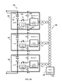
- FIG. 1A depicts a block diagram of one embodiment of battery management system circuitry 100 consistent with the present disclosure.
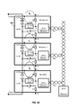
- Figure 1B depicts a block diagram of another embodiment of battery management system circuitry 150 consistent with the present disclosure.
- common elements have common reference designators. The embodiments include similar elements but differ in configuration of those elements, as described herein.
- the battery management systems 100, 150 each include a plurality of battery modules.
- Each battery module 102 includes battery module circuitry.
- each battery management system 100, 150 may include a plurality of battery modules: Module(n), Module(n+1), Module(n+2).
- Each battery module 102 is coupled to central controller circuitry, e.g., central electronic control unit (CECU) 104.
- CECU central electronic control unit
- each battery module 102 may be coupled to the CECU 104 by a bus 106.
- the CECU 104 may include memory 124.
- a specific battery module will be referred herein to as “Module(x)" where x is n, n+1 or n+2, and an individual battery module that may be any of the plurality of battery modules will be referred to herein as “battery module 102".
- the bus 106 is configured to provide communication between the CECU 104 and each battery module 102.
- the bus 106 may be a serial bus configured for serial communication.
- the bus may be a CAN bus, as may be known to those skilled in the art.
- One or more messages may be communicated between the CECU 104 and one or more of the battery modules 102 using bus 106.
- a message may include commands, e.g., instructions, identifier(s) and/or data.
- each message may include an identifier.
- the identifier may be, e.g., an address corresponding to an individual battery module 102, or an identifier corresponding to the plurality of battery modules.
- the identifier may correspond to the battery module(s) that are to receive the message and/or may be requested to respond to the message.
- command may include an instruction to store the identifier, corresponding to an address to be associated with the battery module.
- Data may include the address to be assigned to the battery module 102.
- data may include a parameter associated with the battery module. Parameters include internal and/or external temperature, battery voltage and/or current associated with the battery module.
- a command may include other instructions as are evident those skilled in the art.
- Each battery module 102 includes a plurality of battery cells (“battery”) 110 coupled between a first terminal (LVCC) and a second terminal (LGND).
- a battery 110 may include Lithium-Ion, NiMH (Nickel-Metal Hydride), Lead Acid, Fuel Cell, Super Capacitor, or some other energy storage technology.
- Each battery module includes local controller circuitry, e.g., local electronic control unit (LECU) 112, current sensor circuitry 114, switch circuitry 116 and one or more resistors, e.g., R1, R2 118, 120.
- Each resistor R1, R2 may be coupled to a port, e.g., R1 is coupled to port B and R2 is coupled to port C of the battery module 102.
- Each battery module 102 is configured to be coupled to at least one other battery module 102.
- each port B is configured to be coupled to port C of an adjacent battery module.
- Each battery 110 is configured to be coupled to another battery in at least one adjacent battery module.
- terminal LGND of Module (n+2) may be coupled to terminal LVCC of Module (n+1) and terminal LGND of Module (n+1) may be coupled to terminal LVCC of Module (n).
- LVCC of Module (n+2) may be coupled to Vpack+ and terminal LGND of Module (n) may be coupled to Vpack-.
- Each battery 110 has an associated voltage between terminal LVCC and terminal LGND and is configured to provide electrical energy, e.g., current, to a load coupled across Vpack+ and Vpack-.
- the LECU is configured to be coupled to bus 106.
- the LECU 112 is configured to monitor a status of the battery module 102 and/or battery 110 and/or to communicate with the CECU 104 over bus 106.
- the LECU 112 is configured to receive and store the identifier corresponding to the address of the battery module 102, as described herein.
- the LECU 112 may include memory 122 for storing the identifier.
- the CECU 104 is configured to assign the identifier to each battery module, as described herein. For example, the CECU 104 may transmit message(s) to one or more of the battery modules 102. Each LECU 112 may then receive message(s) from the CECU 104 and may respond only to message(s) that are directed to its associated address.
- Each LECU 112 is configured to respond to message(s) that include the identifier associated, i.e., assigned to, the particular battery module 102.
- each battery module 102 may be assigned a unique address relative to each other battery module in the BMS.
- the LECU 112 is coupled to a node, Node A, of the battery module 102.
- the current sensor 114 is coupled between Node A and a terminal of the battery 110.
- the current sensor 114 may be coupled between Node A and the LGND terminal of the battery 110.
- the current sensor 114 includes current sensor circuitry.
- Current sensor circuitry may include a resistor, a diode, a resistor and a diode, and/or other current sense circuitry, known to one skilled in the art.
- One of the resistors, R1 or R2 may be coupled between Node A and a port of battery module 102.
- R2 is coupled between Node A and Port C in BMS 100 and R1 is coupled between Node A and Port B in BMS 150.
- the resistors R1, R2 may be configured to provide protection, e.g., current limiting and overvoltage protection.
- the resistors R1, R2 may provide a voltage divider function with current sensor 114, e.g., to reduce a voltage across the current sensor 114.
- the switch 116 is coupled between a battery terminal, e.g., terminal LGND, and a resistor, e.g., R1 or R2.
- the switch 116 is configured to be controlled by the LECU 112. For example, switch 116 may open or close based on a signal from the LECU. Closing switch 116 may close a loop and allow current to flow from a battery 110 through the switch 116, current sensor 114 and resistors R1, R2.
- the LECU 112 may be configured to provide the signal to open or close switch 116 based on a message from the CECU 104.
- the switch 116 may be a transistor, e.g., a BJT or a FET, a relay or another electronically controllable switch, known to one skilled in the art.
- a non-zero voltage may be detected at Node A, e.g., across current sensor 114, between Node A and battery terminal LGND, by the LECU 112. If no current is flowing, e.g., switch 116 is open, zero voltage may be detected at Node A.
- the detected current may be used to identify and/or select one battery module in the plurality of battery modules, as described herein.
- closing a switch in a first battery module provides a first current path from a battery in a second battery module (e.g., Module (n+1)) through the switch in the first battery module (e.g., Module(n+2)) through a node and current sensor in the second battery module (e.g., Module(n+1)).
- the current sensor 114 in the first battery module e.g., Module(n+2), is not included in the first current path. Rather, the current sensor 114 may be included in a second current path.
- closing a switch in a first battery module provides a current path from a battery in the first battery module (e.g., Module(n+1)) through a current sensor and a node in a second battery module (e.g., Module(n+2)) through the switch in the first battery module (e.g., Module(n+1)).
- FIG. 2A depicts a flowchart 200 of exemplary operations for a assigning addresses to a plurality of battery modules consistent with the present disclosure.
- Program flow may begin at Start 205.
- all local controllers e.g., all LECUs 112 in a battery management system, e.g., BMS 100 or BMS 150, may close switch K, e.g., switch 116.
- central controller e.g., CECU 104
- the message may include an identifier that corresponds to all of the plurality of battery modules.
- each of the plurality of battery modules may be manufactured with a default address.
- the message from the CECU 104 may include an identifier that corresponds to the default address.
- each LECU 112 in the plurality of battery modules may be configured to provide a signal to its associated switch 116 to close in response to the message from the CECU 104.
- Operation 215 may include changing an address associated with a local controller that detects a zero current.
- the LECU may be configured to detect a voltage between Node A and terminal LGND, corresponding to the current sensed by the current sensor, and if a zero voltage is detected, the LECU is configured to store a new address provided by, e.g., the CECU.
- the new address may be unique and may then be the identifier associated with the particular LECU in the particular battery module. Communication between the CECU and the LECU may then include this address to identify the particular battery module in the plurality of battery modules.
- a current below a low current threshold may be considered a zero current, as would be understood by one skilled in the art.
- the local controller with the new address may then open switch K.
- the LECU may receive a message including an identifier corresponding to the LECU's new address and an instruction to open its associated switch K.
- the LECU may then open its associated switch K in response to the message.
- Opening switch K in a first battery module is configured to open a current path that may include a current sensor in a second module, result in a sensed current of zero in the second battery module, as described herein.
- Whether all of the local controllers in a battery management system have been assigned a new, unique address may be determined at operation 225. If all of the local controllers have been assigned a new, unique address, flow may end at operation 230. If not all of the local controllers have been assigned a new, unique address, flow may proceed to operation 215, change address of local controller with detected current equal to zero and the operations may be repeated.
- FIG. 2B depicts another flowchart 250 of exemplary operations for a assigning addresses to a plurality of battery modules consistent with the present disclosure.
- the operations of flowchart 250 may be performed by a central controller, e.g., CECU 104.
- the central controller may include instructions stored in memory 124 that when executed cause the operations of flowchart 250.
- Flow may begin at Start 255.
- the central controller may transmit a message to all local controllers, e.g., LECUs, including an instruction to close switch K at operation 260.
- the central controller may then instruct the local controller(s) with unassigned addresses to detect a current, e.g., detect a potential across a current sensor coupled between Node A and terminal LGND.
- the central controller may then assign a new, unique address to the local controller that with detected current equal to zero.
- the central controller may then instruct the local controller with the newly assigned address to open switch K at operation 275.
- Whether any local controller(s) remain that have not been assigned a new, unique address and have a detected current of zero, may be determined at operation 280. If no such local controllers remain, flow may end 285. If local controller(s) remain that have not been assigned a new, unique address and have a detected current of zero, flow may proceed to operation 270 and operations 270, 275 and 280 may repeat until no local controller(s) remain with unassigned addresses.
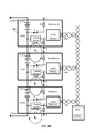
- Figure 3A illustrates current path(s) associated with assigning addresses corresponding to the block diagram of Figure 1A .
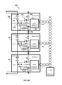
- Figure 3B illustrates current path(s) associated with assigning addresses corresponding to the block diagram of Figure 1B .
- three currents along three current paths, each path including a current sensor and a switch K in the closed state, i.e., conducting, have been added to illustrate operation of each example of a system and method consistent with the present disclosure.
- each switch 116 in an associated battery module 102 may be closed.
- Port C of Module (n+2) is not connected, i.e., is an open circuit.
- I 2 sensed by the current sensor of Module (n+2), is zero.
- I 1 and I 0 are non-zero when switch K of Module(n+2) and switch K of Module(n+1), respectively, are closed.
- the sensed currents of Module(n+1) and Module(n) are non-zero.
- “Non-zero" may be understood as greater than an absolute value of a low current threshold.
- I 1 sensed by Module(n+1), depends on the state of switch K of Module(n+2).
- switch K of Module(n+2) When switch K of Module(n+2) is closed, then I 1 may be non-zero and depends, at least in part, on LVCC of Module(n+1), R1 of Module (n+2), R2 of Module(n+1) and the current sensor of Module(n+1).
- I 0 sensed by Module(n), depends on the state of switch K of Module(n+1).
- switch K of Module(n+1) is closed, then I 0 may be non-zero and depends, at least in part, on LVCC of Module(n), R1 of Module (n+1), R2 of Module(n) and the current sensor of Module(n).
- the address of Module(n+2) (the module with a detected current of zero) may then be changed at operation 220 and the LECU of Module(n+2) may then open switch K of Module(n+2).
- switch K of Module(n+2) When switch K of Module(n+2) is opened, I 1 may then go to zero, I 2 may remain zero and I 0 may remain non-zero.
- detected current of Module(n+1) may be zero.
- the address of Module(n+1) may then be changed and the LECU of Module(n+1) may then open switch K of Module(n+1), resulting in I 0 going to zero. A new address may then be assigned to Module(n).
- flow charts 200, 250 may be performed for any number of battery modules coupled in cascade, e.g., as depicted in Figure 1A and Figure 3A .
- a "top" battery module e.g., Module(n+2)
- Vpack+ e.g., Vpack+
- a position of Module(n+2) may be known based on detecting a zero voltage at Node A of Module(n+2) when all switches K are closed.
- Figure 1A and Figure 3A may be understood as corresponding to a discharge current method.
- each switch 116 in an associated battery module 102 may be closed.
- the embodiment of Figure 3B operates similarly to the embodiment of Figure 3A except that addresses may be assigned from the bottom, i.e., Module(n), to the top, i.e., Module(n+2), rather than from the top to the bottom.
- Port B of Module(n) is not connected, i.e., is an open circuit. Accordingly, I 0 , sensed by the current sensor of Module(n), is zero, and the detected current of Module(n) is zero.
- I 1 and I 2 are non-zero when switch K of Module(n) and switch K of Module(n+1), respectively, are closed.
- the detected currents of Module(n+1) and Module(n+2) are non-zero.
- “Non-zero” may be understood as greater than an absolute value of a low current threshold. Accordingly, I 1 , sensed by Module(n+1), depends on the state of switch K of Module(n). When switch K of Module(n) is closed, then I 1 may be non-zero and depends, at least in part, on LVCC of Module(n), R1 of Module (n+1), R2 of Module(n) and the current sensor of Module(n+1).
- I 2 sensed by Module(n+2), depends on the state of switch K of Module(n+1).
- switch K of Module(n+1) is closed, then I 2 may be non-zero and depends, at least in part, on LVCC of Module(n+1), R1 of Module (n+2), R2 of Module(n+1) and the current sensor of Module(n+2).
- the address of Module(n) (the module with detected current equal to zero) may then be changed at operation 220 and the LECU of Module(n) may then open switch K of Module(n).
- switch K of Module(n) When switch K of Module(n) is opened, I 1 may then go to zero, I 0 may remain zero and I 2 may remain non-zero.
- the detected current of Module(n+1) is zero.
- the address of Module(n+1) may then be changed and the LECU of Module(n+1) may then open switch K of Module(n+1), resulting in I 2 going to zero.
- a new address may then be assigned to Module(n+2).
- flow charts 200, 250 may be performed for any number of battery modules coupled in cascade, e.g., as depicted in Figure 1B and Figure 3B .
- a "bottom" battery module e.g., Module(n)
- Vpack- e.g., Vpack-.
- a position of Module(n) may be known based on detecting a zero voltage at Node A of Module(n) when all switches K are closed.
- Figure 1B and Figure 3B may be understood as corresponding to a charge current method.
- Figure 4A depicts a block diagram of one embodiment of battery management system circuitry 400, including a second switch 410, consistent with the present disclosure.
- Figure 4B depicts a block diagram of another embodiment of battery management system circuitry 450, including the second switch 410, consistent with the present disclosure.
- common elements have common reference designators. These embodiments 400, 450 include similar elements to the embodiments 100, 150 depicted in Figure 1A and Figure 1B , respectively, as described herein.
- the embodiments 400, 450 include a second switch 410.
- the switch 410 is configured to provide a potential VDD from the local controller, LECU, 112 to a current path.
- the potential VDD is configured to be in addition to the potential LVCC provided by the battery 110.
- the potential VDD may facilitate identifying specific battery modules, as described herein, when the potential LVCC provided by a battery 110 is relatively low.
- the second switch 410 is coupled to switch K 116.
- the second switch 410 is configured to couple the switch K 116 to the local ground LGND of a battery module 402 or to an output, LVDD, of the LECU 112.
- the battery system 400 may operate similarly to the battery system 100 of Figures 1A and 3A .
- the switch K 116 is coupled to LVDD, the LECU 112 is configured to provide an additional potential to the current path that includes switch K 116. Operation is otherwise similar to the operation of the battery system 100, as described herein.
- the second switch 410 is coupled to the current sensor 114.
- the second switch 410 is configured to couple the current sensor 114 to the local ground LGND of a battery module 402 or to an output, LVDD, of the LECU 112.
- the battery system 450 may operate similarly to the battery system 150 of Figures 1B and 3B .
- the LECU 112 is configured to provide an additional potential to the current path that includes current sensor 114. Operation is otherwise similar to the operation of the battery system 150, as described herein.
- closing all switches K results in one battery module with zero current through a current sensor and therefore zero detected current.
- this battery module may be positioned at the "top”, e.g., coupled to Vpack+ or at the "bottom", e.g., coupled to Vpack- of the cascade.
- These techniques result in selecting a top or bottom battery module and allows assignment of an identifier, i.e., address, to the battery module.
- This battery module may then be independently controlled to open its associated switch, resulting in a zero voltage at a next battery module in the cascade. The process may be repeated until all of the battery modules in the cascade have been assigned a unique identifier. A count may be kept of the assigned addresses corresponding to a number, N, of battery modules in the cascade.
- the top or bottom module may be identified as the first battery module with zero Node A voltage.
- a position of each other battery module in the cascade may be identified and/or determined based on the detected current (zero or non-zero) of each other battery module. In other words, the position of each other battery module may be determined based on its position in a sequence of zero detected currents, determined according to the flow charts of Figures 2A and/or 2B.
- common battery modules may be manufactured without setting individual address(es) at the time of manufacturing facilitating a lower cost and relatively faster manufacturing process.
- a plurality of generally identical battery modules may be assembled in cascade in a generally random order. Each battery module may then be selected and an identifier assigned, in sequence, providing a cost savings based on volume production of generally identical battery modules.
- Figures 2A and 2B depict exemplary operations according to some embodiments, it is to be understood that in other embodiments all of the operations depicted in Figure 2A and/or Figure 2B may not be necessary. Indeed, it is fully contemplated herein that other embodiments of the present disclosure may include subcombinations of the operations depicted in Figure 2A and/or Figure 2B and/or additional operations. Thus, claims directed to features and/or operations that are not exactly shown in one drawing are deemed within the scope and content of the present disclosure.
- Memory 122, 124 may comprise one or more of the following types of memory: semiconductor firmware memory, programmable memory, non-volatile memory, read only memory, electrically programmable memory, random access memory, flash memory, magnetic disk memory, and/or optical disk memory. Either additionally or alternatively, memory 122, 124 may comprise other and/or later-developed types of computer-readable memory.
- Embodiments of the methods described herein may be implemented using a processor and/or other programmable device. To that end, the methods described herein may be implemented on a tangible computer readable medium having instructions stored thereon that when executed by one or more processors perform the methods.
- the storage medium may include any type of tangible medium, for example, any type of disk including floppy disks, optical disks, compact disk read-only memories (CD-ROMs), compact disk rewritables (CD-RWs), and magneto-optical disks, semiconductor devices such as read-only memories (ROMs), random access memories (RAMs) such as dynamic and static RAMs, erasable programmable read-only memories (EPROMs), electrically erasable programmable read-only memories (EEPROMs), flash memories, magnetic or optical cards, or any type of media suitable for storing electronic instructions.
- ROMs read-only memories
- RAMs random access memories
- EPROMs erasable programmable read-only memories
- EEPROMs electrically erasable programmable read-only memories
- flash memories magnetic or optical cards, or any type of media suitable for storing electronic instructions.
- Circuitry may comprise, for example, singly or in any combination, hardwired circuitry, programmable circuitry, state machine circuitry, and/or firmware that stores instructions executed by programmable circuitry.
Landscapes
- Engineering & Computer Science (AREA)
- Power Engineering (AREA)
- General Chemical & Material Sciences (AREA)
- Chemical & Material Sciences (AREA)
- Chemical Kinetics & Catalysis (AREA)
- Electrochemistry (AREA)
- Manufacturing & Machinery (AREA)
- Life Sciences & Earth Sciences (AREA)
- Sustainable Development (AREA)
- Sustainable Energy (AREA)
- Transportation (AREA)
- Mechanical Engineering (AREA)
- Microelectronics & Electronic Packaging (AREA)
- Secondary Cells (AREA)
- Charge And Discharge Circuits For Batteries Or The Like (AREA)
Abstract
Description
- Battery Management Systems (BMSs) typically include a plurality of battery modules coupled in cascade in order to provide relatively high energy for Electric Vehicles (EVs) and/or Hybrid Electric Vehicles (HEVs). Each battery module typically includes a plurality of battery cells and circuitry configured to monitor a status of the battery cells and to communicate the status to, e.g., a remote control unit.
- It is desirable for each battery module to be manufactured identically to each other battery module, providing savings in both manufacturing cost and the time to manufacture the modules. In operation, however, it may be desirable to individually address each battery module, e.g., in order to identify a particular battery module. It may also be desirable to assemble the plurality of battery modules into a battery management system without consideration of a relative position of each module in the system. Providing unique addresses at manufacturing can be done but adds time and cost to the manufacturing process. It may therefore be desirable to identify and assign unique addresses to battery modules after they have been assembled into a BMS.
- According to one aspect there is disclosed an apparatus. The apparatus may include a first battery module. The first battery module may include a switch configured to open or close a first current path from a first terminal of a battery to a second terminal of the battery when a second battery module is coupled to the first battery module; a current sensor configured to sense a current in a second current path, the second current path different from the first current path; and a local controller configured to control a state of the switch to open or close the switch, wherein closing the switch is configured to close the first current path, the local controller is further configured to detect the sensed current in the second current path, and the local controller is further configured to receive and store an identifier based at least in part on the current detected in the second current path.
- According to another aspect there is disclosed a method for assigning identifiers to a plurality of battery modules. The method may include closing a switch in each battery module, wherein the switch is configured to open or close a first current path from a first terminal of a battery to a second terminal of the battery; detecting a current in each battery module, wherein the current is in a second current path different from the first current path; assigning an address to one battery module if the one battery module has detected zero current in the second current path, wherein the one module is configured to store the assigned address; opening the switch of the one battery module; and repeating the detecting, assigning and opening until the plurality of battery modules have been assigned addresses.
- In yet another aspect there is disclosed a system. The system may include a plurality of battery modules. Each battery module may include a switch configured to open or close a first current path from a first terminal of a battery to a second terminal of the battery when another battery module is coupled to the battery module, a current sensor configured to sense a current in a second current path, the second current path different from the first current path, and a local controller configured to control a state of the switch to open or close the switch, wherein closing the switch is configured to close the first current path, the local controller is further configured to detect the sensed current in the second current path, and the local controller is further configured to receive and store an identifier based at least in part on the current detected in the second path. The system may further include a central controller coupled to a plurality of battery modules, the central controller is configured to provide a message to the local controller of each battery module, the message is configured to cause one or more of the local controllers to close its associated local switch and to detect the current in the second current path, the message is further configured to cause the local controller to store the identifier based at least in part on the detected current.
- Features and advantages of the claimed subject matter will be apparent from the following detailed description of embodiments consistent therewith, which description should be considered with reference to the accompanying drawings, wherein:
-
Figure 1A depicts a block diagram of one embodiment of a system consistent with the present disclosure; -
Figure 1B depicts a block diagram of another embodiment of a system consistent with the present disclosure; -
Figure 2A depicts a flowchart of exemplary operations for a assigning addresses to a plurality of battery modules consistent with the present disclosure; -
Figure 2B depicts another flowchart of exemplary operations for a assigning addresses to a plurality of battery modules consistent with the present disclosure; -
Figure 3A illustrates current flow(s) associated with assigning addresses corresponding to the block diagram ofFigure 1A ; -
Figure 3B illustrates current flow(s) associated with assigning addresses corresponding to the block diagram ofFigure 1B ; -
Figure 4A depicts a block diagram of one embodiment of a system, including a second switch, consistent with the present disclosure; and -
Figure 4B depicts a block diagram of another embodiment of a system, including a second switch, consistent with the present disclosure. - A system, apparatus and/or method consistent with the present disclosure are configured to identify each battery module of a plurality of battery modules in a battery management system (BMS) and to assign an address to each battery module. The system, apparatus and method may allow determination of how many battery modules are in the plurality of battery modules. The system, apparatus and/or method may allow determination of a position of each battery module relative to other battery modules in the BMS.
-
Figure 1A depicts a block diagram of one embodiment of batterymanagement system circuitry 100 consistent with the present disclosure.Figure 1B depicts a block diagram of another embodiment of batterymanagement system circuitry 150 consistent with the present disclosure. In theembodiments - The
battery management systems battery module 102 includes battery module circuitry. For example, eachbattery management system battery module 102 is coupled to central controller circuitry, e.g., central electronic control unit (CECU) 104. For example, eachbattery module 102 may be coupled to the CECU 104 by abus 106. The CECU 104 may includememory 124. For ease of description, a specific battery module will be referred herein to as "Module(x)" where x is n, n+1 or n+2, and an individual battery module that may be any of the plurality of battery modules will be referred to herein as "battery module 102". - The
bus 106 is configured to provide communication between the CECU 104 and eachbattery module 102. Thebus 106 may be a serial bus configured for serial communication. For example, the bus may be a CAN bus, as may be known to those skilled in the art. One or more messages may be communicated between the CECU 104 and one or more of thebattery modules 102 usingbus 106. A message may include commands, e.g., instructions, identifier(s) and/or data. For example, each message may include an identifier. The identifier may be, e.g., an address corresponding to anindividual battery module 102, or an identifier corresponding to the plurality of battery modules. The identifier may correspond to the battery module(s) that are to receive the message and/or may be requested to respond to the message. For example, command may include an instruction to store the identifier, corresponding to an address to be associated with the battery module. Data may include the address to be assigned to thebattery module 102. In another example, data may include a parameter associated with the battery module. Parameters include internal and/or external temperature, battery voltage and/or current associated with the battery module. A command may include other instructions as are evident those skilled in the art. - Each
battery module 102 includes a plurality of battery cells ("battery") 110 coupled between a first terminal (LVCC) and a second terminal (LGND). For example, abattery 110 may include Lithium-Ion, NiMH (Nickel-Metal Hydride), Lead Acid, Fuel Cell, Super Capacitor, or some other energy storage technology. Each battery module includes local controller circuitry, e.g., local electronic control unit (LECU) 112,current sensor circuitry 114,switch circuitry 116 and one or more resistors, e.g., R1, R2 118, 120. Each resistor R1, R2 may be coupled to a port, e.g., R1 is coupled to port B and R2 is coupled to port C of thebattery module 102. Eachbattery module 102 is configured to be coupled to at least oneother battery module 102. For example, each port B is configured to be coupled to port C of an adjacent battery module. Eachbattery 110 is configured to be coupled to another battery in at least one adjacent battery module. For example, terminal LGND of Module (n+2) may be coupled to terminal LVCC of Module (n+1) and terminal LGND of Module (n+1) may be coupled to terminal LVCC of Module (n). In this example, LVCC of Module (n+2) may be coupled to Vpack+ and terminal LGND of Module (n) may be coupled to Vpack-. Eachbattery 110 has an associated voltage between terminal LVCC and terminal LGND and is configured to provide electrical energy, e.g., current, to a load coupled across Vpack+ and Vpack-. Although these examples include three modules, more or fewer modules may be included in a BMS, consistent with the present disclosure, as would be evident to one of ordinary skill in the art. - The LECU is configured to be coupled to
bus 106. TheLECU 112 is configured to monitor a status of thebattery module 102 and/orbattery 110 and/or to communicate with theCECU 104 overbus 106. TheLECU 112 is configured to receive and store the identifier corresponding to the address of thebattery module 102, as described herein. TheLECU 112 may includememory 122 for storing the identifier. TheCECU 104 is configured to assign the identifier to each battery module, as described herein. For example, theCECU 104 may transmit message(s) to one or more of thebattery modules 102. EachLECU 112 may then receive message(s) from theCECU 104 and may respond only to message(s) that are directed to its associated address. EachLECU 112 is configured to respond to message(s) that include the identifier associated, i.e., assigned to, theparticular battery module 102. In other words, eachbattery module 102 may be assigned a unique address relative to each other battery module in the BMS. - The
LECU 112 is coupled to a node, Node A, of thebattery module 102. Thecurrent sensor 114 is coupled between Node A and a terminal of thebattery 110. For example, thecurrent sensor 114 may be coupled between Node A and the LGND terminal of thebattery 110. Thecurrent sensor 114 includes current sensor circuitry. Current sensor circuitry may include a resistor, a diode, a resistor and a diode, and/or other current sense circuitry, known to one skilled in the art. One of the resistors, R1 or R2, may be coupled between Node A and a port ofbattery module 102. For example, R2 is coupled between Node A and Port C inBMS 100 and R1 is coupled between Node A and Port B inBMS 150. For example, the resistors R1, R2 may be configured to provide protection, e.g., current limiting and overvoltage protection. The resistors R1, R2 may provide a voltage divider function withcurrent sensor 114, e.g., to reduce a voltage across thecurrent sensor 114. - The
switch 116 is coupled between a battery terminal, e.g., terminal LGND, and a resistor, e.g., R1 or R2. Theswitch 116 is configured to be controlled by theLECU 112. For example, switch 116 may open or close based on a signal from the LECU.Closing switch 116 may close a loop and allow current to flow from abattery 110 through theswitch 116,current sensor 114 and resistors R1, R2. TheLECU 112 may be configured to provide the signal to open orclose switch 116 based on a message from theCECU 104. Theswitch 116 may be a transistor, e.g., a BJT or a FET, a relay or another electronically controllable switch, known to one skilled in the art. If current is flowing, a non-zero voltage may be detected at Node A, e.g., acrosscurrent sensor 114, between Node A and battery terminal LGND, by theLECU 112. If no current is flowing, e.g.,switch 116 is open, zero voltage may be detected at Node A. The detected current may be used to identify and/or select one battery module in the plurality of battery modules, as described herein. - For example, for
BMS 100 ofFigure 1A , whenswitch 116 of Module(n+2) is closed, current may flow from terminal LVCC ofbattery 110 of Module(n+1) throughswitch 116 of Module(n+2) through R1 of Module(n+2) to port B of Module(n+2), from Port B of Module(n+2) to Port C of Module(n+1), through R2 of Module(n+1) through Node A of Module (n+1) throughcurrent sensor 114 of Module(n+1) to terminal LGND ofbattery 110 of Module(n+1). In other words, closing a switch in a first battery module, e.g., Module(n+2), provides a first current path from a battery in a second battery module (e.g., Module (n+1)) through the switch in the first battery module (e.g., Module(n+2)) through a node and current sensor in the second battery module (e.g., Module(n+1)). Thecurrent sensor 114 in the first battery module, e.g., Module(n+2), is not included in the first current path. Rather, thecurrent sensor 114 may be included in a second current path. - In another example, for
BMS 150 ofFigure 1B , whenswitch 116 of Module(n+1) is closed, current may flow from terminal LVCC ofbattery 110 of Module(n+1) throughcurrent sensor 114 of Module(n+2) to Node A of Module(n+2), from Node A of Module(n+2) through R1 of Module(n+2) to port B of Module(n+2), from Port B of Module(n+2) to Port C of Module(n+1) through R2 of Module(n+1) throughswitch 116 of Module(n+1) to terminal LGND ofbattery 110 of Module(n+1). In other words, closing a switch in a first battery module, e.g., Module(n+1), provides a current path from a battery in the first battery module (e.g., Module(n+1)) through a current sensor and a node in a second battery module (e.g., Module(n+2)) through the switch in the first battery module (e.g., Module(n+1)). -
Figure 2A depicts aflowchart 200 of exemplary operations for a assigning addresses to a plurality of battery modules consistent with the present disclosure. Program flow may begin atStart 205. Atoperation 210, all local controllers, e.g., allLECUs 112, in a battery management system, e.g.,BMS 100 orBMS 150, may close switch K, e.g.,switch 116. For example, central controller, e.g.,CECU 104, may broadcast a message to each of the plurality of battery modules including an instruction to close switch K. In other words, the message may include an identifier that corresponds to all of the plurality of battery modules. In another example, each of the plurality of battery modules may be manufactured with a default address. In this example, the message from theCECU 104 may include an identifier that corresponds to the default address. In both examples, eachLECU 112 in the plurality of battery modules may be configured to provide a signal to its associatedswitch 116 to close in response to the message from theCECU 104. -
Operation 215 may include changing an address associated with a local controller that detects a zero current. For example, the LECU may be configured to detect a voltage between Node A and terminal LGND, corresponding to the current sensed by the current sensor, and if a zero voltage is detected, the LECU is configured to store a new address provided by, e.g., the CECU. The new address may be unique and may then be the identifier associated with the particular LECU in the particular battery module. Communication between the CECU and the LECU may then include this address to identify the particular battery module in the plurality of battery modules. A current below a low current threshold may be considered a zero current, as would be understood by one skilled in the art. - At
operation 220, the local controller with the new address may then open switch K. For example, the LECU may receive a message including an identifier corresponding to the LECU's new address and an instruction to open its associated switch K. The LECU may then open its associated switch K in response to the message. Opening switch K in a first battery module is configured to open a current path that may include a current sensor in a second module, result in a sensed current of zero in the second battery module, as described herein. Whether all of the local controllers in a battery management system have been assigned a new, unique address may be determined atoperation 225. If all of the local controllers have been assigned a new, unique address, flow may end at operation 230. If not all of the local controllers have been assigned a new, unique address, flow may proceed tooperation 215, change address of local controller with detected current equal to zero and the operations may be repeated. -
Figure 2B depicts anotherflowchart 250 of exemplary operations for a assigning addresses to a plurality of battery modules consistent with the present disclosure. For example, the operations offlowchart 250 may be performed by a central controller, e.g.,CECU 104. The central controller may include instructions stored inmemory 124 that when executed cause the operations offlowchart 250. Flow may begin atStart 255. The central controller may transmit a message to all local controllers, e.g., LECUs, including an instruction to close switch K atoperation 260. Atoperation 265, the central controller may then instruct the local controller(s) with unassigned addresses to detect a current, e.g., detect a potential across a current sensor coupled between Node A and terminal LGND. Atoperation 270, the central controller may then assign a new, unique address to the local controller that with detected current equal to zero. The central controller may then instruct the local controller with the newly assigned address to open switch K atoperation 275. Whether any local controller(s) remain that have not been assigned a new, unique address and have a detected current of zero, may be determined atoperation 280. If no such local controllers remain, flow may end 285. If local controller(s) remain that have not been assigned a new, unique address and have a detected current of zero, flow may proceed tooperation 270 andoperations - The operations of
flowcharts Figure 3A andFigure 3B .Figure 3A illustrates current path(s) associated with assigning addresses corresponding to the block diagram ofFigure 1A .Figure 3B illustrates current path(s) associated with assigning addresses corresponding to the block diagram ofFigure 1B . In bothFigure 3A and3B , three currents along three current paths, each path including a current sensor and a switch K in the closed state, i.e., conducting, have been added to illustrate operation of each example of a system and method consistent with the present disclosure. As should be evident to one of ordinary skill in the art, assuming LVCC is not zero, whether a current, I0, I1, I2, sensed bycurrent sensor 114 in a first battery module is zero depends on a state ofswitch 116 of a second battery module. - Referring first to
Figure 3A , beginning withoperations switch 116 in an associatedbattery module 102 may be closed. Port C of Module (n+2) is not connected, i.e., is an open circuit. Accordingly I2, sensed by the current sensor of Module (n+2), is zero. I1 and I0 are non-zero when switch K of Module(n+2) and switch K of Module(n+1), respectively, are closed. The sensed currents of Module(n+1) and Module(n) are non-zero. "Non-zero" may be understood as greater than an absolute value of a low current threshold. Accordingly, I1, sensed by Module(n+1), depends on the state of switch K of Module(n+2). When switch K of Module(n+2) is closed, then I1 may be non-zero and depends, at least in part, on LVCC of Module(n+1), R1 of Module (n+2), R2 of Module(n+1) and the current sensor of Module(n+1). Similarly, I0, sensed by Module(n), depends on the state of switch K of Module(n+1). When switch K of Module(n+1) is closed, then I0 may be non-zero and depends, at least in part, on LVCC of Module(n), R1 of Module (n+1), R2 of Module(n) and the current sensor of Module(n). - The address of Module(n+2) (the module with a detected current of zero) may then be changed at
operation 220 and the LECU of Module(n+2) may then open switch K of Module(n+2). When switch K of Module(n+2) is opened, I1 may then go to zero, I2 may remain zero and I0 may remain non-zero. Based on I1 being zero, detected current of Module(n+1) may be zero. The address of Module(n+1) may then be changed and the LECU of Module(n+1) may then open switch K of Module(n+1), resulting in I0 going to zero. A new address may then be assigned to Module(n). - The operations of
flow charts Figure 1A andFigure 3A . It may be appreciated that a "top" battery module, e.g., Module(n+2), is coupled to Vpack+. In other words, a position of Module(n+2) may be known based on detecting a zero voltage at Node A of Module(n+2) when all switches K are closed.Figure 1A andFigure 3A may be understood as corresponding to a discharge current method. - Referring to
Figure 3B , beginning withoperations switch 116 in an associatedbattery module 102 may be closed. The embodiment ofFigure 3B operates similarly to the embodiment ofFigure 3A except that addresses may be assigned from the bottom, i.e., Module(n), to the top, i.e., Module(n+2), rather than from the top to the bottom. Port B of Module(n) is not connected, i.e., is an open circuit. Accordingly, I0, sensed by the current sensor of Module(n), is zero, and the detected current of Module(n) is zero. I1 and I2 are non-zero when switch K of Module(n) and switch K of Module(n+1), respectively, are closed. The detected currents of Module(n+1) and Module(n+2) are non-zero. "Non-zero" may be understood as greater than an absolute value of a low current threshold. Accordingly, I1, sensed by Module(n+1), depends on the state of switch K of Module(n). When switch K of Module(n) is closed, then I1 may be non-zero and depends, at least in part, on LVCC of Module(n), R1 of Module (n+1), R2 of Module(n) and the current sensor of Module(n+1). Similarly, I2, sensed by Module(n+2), depends on the state of switch K of Module(n+1). When switch K of Module(n+1) is closed, then I2 may be non-zero and depends, at least in part, on LVCC of Module(n+1), R1 of Module (n+2), R2 of Module(n+1) and the current sensor of Module(n+2). - The address of Module(n) (the module with detected current equal to zero) may then be changed at
operation 220 and the LECU of Module(n) may then open switch K of Module(n). When switch K of Module(n) is opened, I1 may then go to zero, I0 may remain zero and I2 may remain non-zero. Based on I1 being zero, the detected current of Module(n+1) is zero. The address of Module(n+1) may then be changed and the LECU of Module(n+1) may then open switch K of Module(n+1), resulting in I2 going to zero. A new address may then be assigned to Module(n+2). - The operations of
flow charts Figure 1B andFigure 3B . It may be appreciated that a "bottom" battery module, e.g., Module(n), is coupled to Vpack-. In other words, a position of Module(n) may be known based on detecting a zero voltage at Node A of Module(n) when all switches K are closed.Figure 1B andFigure 3B may be understood as corresponding to a charge current method. -
Figure 4A depicts a block diagram of one embodiment of batterymanagement system circuitry 400, including asecond switch 410, consistent with the present disclosure.Figure 4B depicts a block diagram of another embodiment of batterymanagement system circuitry 450, including thesecond switch 410, consistent with the present disclosure. In theembodiments embodiments embodiments Figure 1A andFigure 1B , respectively, as described herein. - The
embodiments second switch 410. Theswitch 410 is configured to provide a potential VDD from the local controller, LECU, 112 to a current path. The potential VDD is configured to be in addition to the potential LVCC provided by thebattery 110. The potential VDD may facilitate identifying specific battery modules, as described herein, when the potential LVCC provided by abattery 110 is relatively low. - Referring to
Figure 4A , thesecond switch 410 is coupled to switchK 116. Thesecond switch 410 is configured to couple theswitch K 116 to the local ground LGND of abattery module 402 or to an output, LVDD, of theLECU 112. When theswitch K 116 is coupled to the local ground LGND, thebattery system 400 may operate similarly to thebattery system 100 ofFigures 1A and3A . When theswitch K 116 is coupled to LVDD, theLECU 112 is configured to provide an additional potential to the current path that includesswitch K 116. Operation is otherwise similar to the operation of thebattery system 100, as described herein. - Referring to
Figure 4B , thesecond switch 410 is coupled to thecurrent sensor 114. Thesecond switch 410 is configured to couple thecurrent sensor 114 to the local ground LGND of abattery module 402 or to an output, LVDD, of theLECU 112. When thecurrent sensor 114 is coupled to the local ground LGND, thebattery system 450 may operate similarly to thebattery system 150 ofFigures 1B and3B . When thecurrent sensor 114 is coupled to LVDD, theLECU 112 is configured to provide an additional potential to the current path that includescurrent sensor 114. Operation is otherwise similar to the operation of thebattery system 150, as described herein. - Accordingly, for the embodiments depicted in
Figures 1A ,3A and4A andFigures 1B ,3B and4B , closing all switches K results in one battery module with zero current through a current sensor and therefore zero detected current. Depending on the configuration of the battery module circuitry, this battery module may be positioned at the "top", e.g., coupled to Vpack+ or at the "bottom", e.g., coupled to Vpack- of the cascade. These techniques result in selecting a top or bottom battery module and allows assignment of an identifier, i.e., address, to the battery module. This battery module may then be independently controlled to open its associated switch, resulting in a zero voltage at a next battery module in the cascade. The process may be repeated until all of the battery modules in the cascade have been assigned a unique identifier. A count may be kept of the assigned addresses corresponding to a number, N, of battery modules in the cascade. - If the configuration of the battery module circuitry is known for all of the battery modules in the cascade, then the top or bottom module may be identified as the first battery module with zero Node A voltage. A position of each other battery module in the cascade may be identified and/or determined based on the detected current (zero or non-zero) of each other battery module. In other words, the position of each other battery module may be determined based on its position in a sequence of zero detected currents, determined according to the flow charts of
Figures 2A and/or 2B. - Advantageously, common battery modules may be manufactured without setting individual address(es) at the time of manufacturing facilitating a lower cost and relatively faster manufacturing process. A plurality of generally identical battery modules may be assembled in cascade in a generally random order. Each battery module may then be selected and an identifier assigned, in sequence, providing a cost savings based on volume production of generally identical battery modules.
- Of course, while
Figures 2A and 2B depict exemplary operations according to some embodiments, it is to be understood that in other embodiments all of the operations depicted inFigure 2A and/orFigure 2B may not be necessary. Indeed, it is fully contemplated herein that other embodiments of the present disclosure may include subcombinations of the operations depicted inFigure 2A and/orFigure 2B and/or additional operations. Thus, claims directed to features and/or operations that are not exactly shown in one drawing are deemed within the scope and content of the present disclosure. -
Memory memory - Embodiments of the methods described herein may be implemented using a processor and/or other programmable device. To that end, the methods described herein may be implemented on a tangible computer readable medium having instructions stored thereon that when executed by one or more processors perform the methods. The storage medium may include any type of tangible medium, for example, any type of disk including floppy disks, optical disks, compact disk read-only memories (CD-ROMs), compact disk rewritables (CD-RWs), and magneto-optical disks, semiconductor devices such as read-only memories (ROMs), random access memories (RAMs) such as dynamic and static RAMs, erasable programmable read-only memories (EPROMs), electrically erasable programmable read-only memories (EEPROMs), flash memories, magnetic or optical cards, or any type of media suitable for storing electronic instructions.
- Unless specifically stated otherwise, as apparent from the preceding discussions, it is appreciated that throughout the specification discussions utilizing terms such as "operations," "processing," "computing," "calculating," "determining," or the like, refer to the action and/or processes of a computer or computing system, or similar electronic computing device or apparatus, that manipulate and/or transform data represented as physical, such as electronic, quantities within the computing system's registers and/or memories into other data similarly represented as physical quantities within the computing system's memories, registers or other such information storage, transmission or display devices.
- "Circuitry", as used in any embodiment herein, may comprise, for example, singly or in any combination, hardwired circuitry, programmable circuitry, state machine circuitry, and/or firmware that stores instructions executed by programmable circuitry.
- The terms and expressions which have been employed herein are used as terms of description and not of limitation, and there is no intention, in the use of such terms and expressions, of excluding any equivalents of the features shown and described (or portions thereof), and it is recognized that various modifications are possible within the scope of the claims. Accordingly, the claims are intended to cover all such equivalents.
Claims (16)
- An apparatus, comprising:a battery module comprising:a switch configured to open or close a first current path from a first terminal of a battery to a second terminal of the battery when another battery module is coupled to the battery module;a current sensor configured to sense a current in a second current path, the second current path different from the first current path; anda local controller configured to control a state of the switch to open or close the switch, wherein closing the switch is configured to close the first current path, the local controller is further configured to detect the sensed current in the second current path, and the local controller is further configured to receive and store an identifier based at least in part on the current detected in the second current path.
- The apparatus of claim 1 wherein the battery is in the battery module.
- The apparatus of claim 1 wherein the battery is in the another battery module.
- The apparatus of claim 1, further comprising:a first resistor coupled to the switch wherein the first resistor is included in the first current path; anda second resistor coupled to the current sensor wherein the second resistor is included in the second current path.
- The apparatus of claim 1, wherein the local controller is further configured to store the identifier when the current detected in the second current path is zero.
- The apparatus of claim 1, wherein the battery module is configured to be coupled to a central controller via a bus and the central controller is configured to provide the identifier to the local controller.
- A method for assigning identifiers to a plurality of battery modules, the method comprising:closing a switch in each battery module, wherein the switch is configured to open or close a first current path from a first terminal of a battery to a second terminal of the battery;detecting a current in each battery module, wherein the current is in a second current path different from the first current path;assigning an address to one battery module based at least in part on the detected current in the one battery module, wherein the one module is configured to store the assigned address;opening the switch of the one battery module; andrepeating the detecting, assigning and opening until the plurality of battery modules have been assigned addresses.
- The method of claim 7, further comprising determining a position of each battery module based, at least in part, on the detected current in each battery module.
- The method of claim 7, further comprising determining a number of battery modules in the cascade based, at least in part, on the detected current in each battery module.
- The method of claim 7, further comprising receiving a message from a central controller, wherein the message comprises at least one of an instruction to close at least one switch in the plurality of battery modules, an instruction to open an associated switch if the detected current for the associated battery module is zero, and the address to be assigned to the one battery module.
- The method of claim 7, wherein the detected current in the one battery module is zero.
- The method of claim 7, wherein the address is stored in a local controller in the one battery module and corresponds to an identifier of the one battery module.
- A system comprising a plurality of apparatus according to one of claims 1 to 6, further comprising:a central controller coupled to the plurality of battery modules, the central controller is configured to provide a message to the local controller of each battery module, the message is configured to cause one or more of the local controllers to close its associated local switch and to detect the current in the second current path, the message is further configured to cause the local controller to store the identifier based at least in part on the detected current.
- The system of claim 13, wherein the central controller is further configured to determine a position of each battery module relative to each other battery module based, at least in part, on the detected current in each battery module.
- The system of claim 13, wherein the central controller is further configured to determine a number of battery modules in the plurality, at least in part, on the detected current in each battery module.
- The system of claim 13, wherein each battery module is coupled to the central controller via a bus.
Applications Claiming Priority (1)
| Application Number | Priority Date | Filing Date | Title |
|---|---|---|---|
| US12/836,632 US8525477B2 (en) | 2010-07-15 | 2010-07-15 | Assigning addresses to multiple cascade battery modules in electric or electric hybrid vehicles |
Publications (2)
| Publication Number | Publication Date |
|---|---|
| EP2408053A2 true EP2408053A2 (en) | 2012-01-18 |
| EP2408053A3 EP2408053A3 (en) | 2013-05-29 |
Family
ID=44142126
Family Applications (1)
| Application Number | Title | Priority Date | Filing Date |
|---|---|---|---|
| EP20110174102 Withdrawn EP2408053A3 (en) | 2010-07-15 | 2011-07-15 | Assigning addresses to multiple cascade battery modules |
Country Status (4)
| Country | Link |
|---|---|
| US (1) | US8525477B2 (en) |
| EP (1) | EP2408053A3 (en) |
| CN (1) | CN102340159B (en) |
| TW (1) | TW201212472A (en) |
Cited By (10)
| Publication number | Priority date | Publication date | Assignee | Title |
|---|---|---|---|---|
| WO2013143779A1 (en) * | 2012-03-28 | 2013-10-03 | Robert Bosch Gmbh | Method for activating a plurality of monitoring units for a battery, battery and motor vehicle having said battery |
| WO2013189875A1 (en) * | 2012-06-22 | 2013-12-27 | Robert Bosch Gmbh | Battery comprising at least one semiconductor-based separating device |
| JP2015526819A (en) * | 2012-08-23 | 2015-09-10 | エルジー・ケム・リミテッド | Battery pack monitoring system and method for assigning a binary ID to a microprocessor in a battery pack monitoring system |
| EP3035068A1 (en) * | 2014-12-10 | 2016-06-22 | Datang NXP Semiconductors Co., Ltd. | Method and apparatus for detecting degraded contacts in battery packs |
| CN106655323A (en) * | 2016-10-11 | 2017-05-10 | 河海大学常州校区 | High-power power battery pack management system |
| ITUB20169952A1 (en) * | 2016-01-13 | 2017-07-13 | Genport Srl | Electronic regulation device for battery type electrical energy storage devices |
| EP3096431A4 (en) * | 2014-02-24 | 2017-09-27 | LG Chem, Ltd. | Battery management unit and method for setting identifier by using frequency modulation |
| GB2575540A (en) * | 2018-05-29 | 2020-01-15 | Continental Powertrain Usa Llc | Automatic location based addressing method for network participants in a serial bus system |
| US10826138B2 (en) | 2014-12-10 | 2020-11-03 | Datang Nxp Semiconductors Co., Ltd. | Method and apparatus for contact detection in battery packs |
| US11310073B2 (en) | 2020-03-04 | 2022-04-19 | Teknoware Oy | Methods and arrangements for arranging data communication between electronic devices in a transportation means |
Families Citing this family (55)
| Publication number | Priority date | Publication date | Assignee | Title |
|---|---|---|---|---|
| CN102255978B (en) | 2010-05-20 | 2014-08-13 | 凹凸电子(武汉)有限公司 | Address configuration device, method and system |
| US8015452B2 (en) | 2010-08-31 | 2011-09-06 | O2Micro International, Ltd. | Flexible bus architecture for monitoring and control of battery pack |
| US9296348B2 (en) * | 2010-09-30 | 2016-03-29 | Sanyo Electric Co., Ltd. | Power supply device and vehicle using the same |
| WO2012060755A1 (en) * | 2010-11-05 | 2012-05-10 | Alelion Batteries Ab | Battery module system and method for initialising battery modules |
| JP5608051B2 (en) * | 2010-11-09 | 2014-10-15 | 株式会社ケーヒン | Communications system |
| US9136566B2 (en) * | 2011-07-27 | 2015-09-15 | Hitachi, Ltd. | Battery system |
| DE102011085787A1 (en) * | 2011-11-04 | 2013-05-08 | Sb Limotive Company Ltd. | Battery management unit with a variety of monitoring IC chips |
| KR101539689B1 (en) * | 2012-02-20 | 2015-07-27 | 주식회사 엘지화학 | System and method for identifier allowcation of multi-bms |
| CN102582462B (en) * | 2012-02-28 | 2014-03-26 | 华霆(合肥)动力技术有限公司 | Electric vehicle battery management system |
| EP2641783B1 (en) | 2012-03-20 | 2016-04-20 | Samsung SDI Co., Ltd. | Battery pack and method of controlling the same |
| CN103376752B (en) * | 2012-04-26 | 2015-07-29 | 石家庄杰泰特动力能源有限公司 | A kind of automobile battery module automatic addressing watch-dog |
| CN102842939B (en) * | 2012-09-28 | 2015-06-17 | 无锡华润矽科微电子有限公司 | Battery management system and battery management method |
| DE102012223530B4 (en) * | 2012-12-18 | 2023-07-06 | Robert Bosch Gmbh | Dynamic line termination of communication buses in battery module monitoring circuits and a method of performing line termination during initialization of the monitoring system |
| CN103336486B (en) * | 2012-12-19 | 2015-11-18 | 惠州市亿能电子有限公司 | A kind of battery modules address distribution method of battery energy storage system |
| US8901888B1 (en) | 2013-07-16 | 2014-12-02 | Christopher V. Beckman | Batteries for optimizing output and charge balance with adjustable, exportable and addressable characteristics |
| WO2015122908A1 (en) | 2014-02-14 | 2015-08-20 | Hewlett Packard Development Company, L.P. | Electronic device and circuit boards thereof |
| DE102015111015B4 (en) * | 2015-07-08 | 2025-02-20 | Dr. Ing. H.C. F. Porsche Aktiengesellschaft | Method and device for locating a battery module among several electrically connected battery modules of a traction battery |
| EP3370298B1 (en) * | 2015-10-30 | 2024-03-06 | Kabushiki Kaisha Toshiba | Battery control apparatus and battery system |
| CN106707171B (en) * | 2015-11-16 | 2019-10-18 | 上海汽车集团股份有限公司 | Systems and methods for detecting faulty battery cells |
| CN105657079B (en) * | 2015-12-30 | 2019-02-12 | 华为技术有限公司 | Address information setting device and method |
| US10013379B2 (en) * | 2016-02-19 | 2018-07-03 | Nxp B.V. | Auto-addressing of communication nodes |
| CN107785940B (en) * | 2016-08-25 | 2021-06-29 | 太普动力新能源(常熟)股份有限公司 | Power supply control method of multi-battery module parallel architecture |
| CN106602670B (en) * | 2017-01-24 | 2019-04-23 | 成都芯源系统有限公司 | Electronic equipment, power supply and control method of power supply |
| GB2543710B (en) | 2017-02-15 | 2018-07-11 | 02Micro Inc | Systems and methods for charging a battery pack |
| GB2559708A (en) * | 2017-02-15 | 2018-08-15 | O2Micro Inc | Systems and methods for charging a battery pack |
| JP6906326B2 (en) * | 2017-02-23 | 2021-07-21 | 株式会社東芝 | Battery device and control method of battery device |
| CN108705936A (en) * | 2017-03-23 | 2018-10-26 | 恒大法拉第未来智能汽车(广东)有限公司 | Battery modules and its method and control unit and electric vehicle |
| WO2018231810A1 (en) | 2017-06-12 | 2018-12-20 | Tae Technologies, Inc. | Multi-level multi-quadrant hysteresis current controllers and methods for control thereof |
| EA202090065A1 (en) | 2017-06-16 | 2020-04-17 | Таэ Текнолоджиз, Инк. | MULTILEVEL HYSTERESIS VOLTAGE CONTROLLERS FOR VOLTAGE MODULATORS AND METHODS FOR THEIR CONTROL |
| DE102017115808A1 (en) * | 2017-07-13 | 2019-01-17 | Technische Universität München | Method for identifying interconnection topologies of energy storage systems |
| CN107437640A (en) * | 2017-07-17 | 2017-12-05 | 深圳市佰控技术有限公司 | The means of communication of battery management system and battery management system |
| JP7107672B2 (en) * | 2017-12-08 | 2022-07-27 | エイブリック株式会社 | Battery protection IC and battery management system |
| EP3503477A1 (en) * | 2017-12-22 | 2019-06-26 | ICRealisations BVBA | System and method for determining the position of nodes in a two-wire bus system |
| TWI669882B (en) | 2018-02-14 | 2019-08-21 | 車王電子股份有限公司 | Electric power system and its management method |
| MX2020009845A (en) * | 2018-03-22 | 2020-10-15 | Tae Tech Inc | SYSTEMS AND METHODS FOR POWER MANAGEMENT AND CONTROL. |
| US20200139821A1 (en) * | 2018-11-02 | 2020-05-07 | Kabushiki Kaisha Toshiba | Power supply device |
| CN111354986A (en) * | 2018-12-21 | 2020-06-30 | 太普动力新能源(常熟)股份有限公司 | Method and device for controlling automatic distribution of identification codes of battery module |
| CA3134697A1 (en) | 2019-03-29 | 2020-10-08 | Tae Technologies, Inc. | Module-based energy systems having converter-source modules and methods related thereto |
| US12556017B2 (en) | 2019-05-30 | 2026-02-17 | Tae Technologies, Inc. | Advanced battery charging on modular levels of energy storage systems |
| CN110933200A (en) * | 2019-11-29 | 2020-03-27 | 四川长虹电器股份有限公司 | BMS communication address configuration system and method based on electronic switch |
| KR102861413B1 (en) * | 2020-02-13 | 2025-09-17 | 주식회사 엘지에너지솔루션 | Battery control system, battery pack, electric vehicle, and control method for the battery control system |
| CN111354990B (en) * | 2020-02-25 | 2023-03-24 | 深圳市安仕新能源科技有限公司 | Battery pack, identification information distribution system and method thereof, and storage medium |
| CA3178859A1 (en) | 2020-04-14 | 2021-10-21 | Tae Technologies, Inc. | Modular cascaded energy systems with a cooling apparatus and with replaceable energy source capability |
| CA3191441A1 (en) | 2020-04-14 | 2021-10-21 | Tae Technologies, Inc. | Systems, devices, and methods for charging and discharging module-based cascaded energy systems |
| IL298081A (en) | 2020-05-14 | 2023-01-01 | Tae Tech Inc | Systems, devices, and methods for rail-based and other electric vehicles with modular cascaded energy systems |
| US20240359595A1 (en) * | 2020-08-24 | 2024-10-31 | Tae Technologies, Inc. | Modular Cascaded Energy Systems with a Cooling Apparatus and with Replaceable Energy Source Capability |
| AU2021350186A1 (en) | 2020-09-28 | 2023-05-11 | Tae Technologies, Inc. | Multi-phase module-based energy system frameworks and methods related thereto |
| WO2022072330A1 (en) | 2020-09-30 | 2022-04-07 | Tae Technologies, Inc. | Systems, devices, and methods for intraphase and interphase balancing in module-based cascaded energy systems |
| AU2022207104A1 (en) | 2021-01-13 | 2023-07-20 | Tae Technologies, Inc. | Systems, devices, and methods for module-based cascaded energy systems |
| CN112910053B (en) * | 2021-03-15 | 2025-03-25 | 宁德新能源科技有限公司 | Electric device, battery pack, BMS system and bus matching resistor access method |
| WO2022240415A1 (en) * | 2021-05-13 | 2022-11-17 | Green Cubes Technology, Llc | Modular battery system with isolated equalizer |
| EP4367770A4 (en) | 2021-07-07 | 2025-06-18 | TAE Technologies, Inc. | SYSTEMS, DEVICES AND METHODS FOR CASCADE ENERGY SYSTEMS BASED ON MODULES CONFIGURED TO INTERFACE WITH RENEWABLE ENERGY SOURCES |
| CN114017118B (en) * | 2021-10-12 | 2023-11-03 | 天地(常州)自动化股份有限公司 | Multifunctional addressing device and addressing method for multi-loop mining explosion-proof switch |
| KR20230072833A (en) * | 2021-11-18 | 2023-05-25 | 주식회사 엘지에너지솔루션 | Battery management apparatus and method for comunicating using the same |
| CN118740806B (en) * | 2024-07-25 | 2026-04-07 | 孝感楚能新能源创新科技有限公司 | Battery management system, addressing method, device and equipment of battery management system |
Family Cites Families (64)
| Publication number | Priority date | Publication date | Assignee | Title |
|---|---|---|---|---|
| US4716354A (en) | 1985-11-12 | 1987-12-29 | Norand Corporation | Automatic voltage regulator means providing a dual low power responsive and output-voltage-controlling regulator signal particularly for a plural source battery powered system |
| FR2543767B1 (en) | 1983-03-29 | 1985-06-14 | Cit Alcatel | DEVICE FOR EXCHANGING CODED MESSAGES BETWEEN STATIONS |
| DE3427891A1 (en) | 1984-07-28 | 1986-01-30 | Philips Patentverwaltung Gmbh, 2000 Hamburg | ARRANGEMENT FOR TRANSFER OF INFORMATION WITH RECONFIGURATION |
| US4773005A (en) | 1984-09-07 | 1988-09-20 | Tektronix, Inc. | Dynamic address assignment system |
| US4962378A (en) | 1987-11-09 | 1990-10-09 | Ncr Corporation | Multi-user serial bus system |
| US5282193A (en) | 1990-11-24 | 1994-01-25 | Fujitsu Limited | Maintenance signal transmission system |
| US5423050A (en) | 1991-11-27 | 1995-06-06 | Ncr Corporation | Intermodule test across system bus utilizing serial test bus |
| US5424657A (en) | 1993-03-19 | 1995-06-13 | Apple Computer, Inc. | Method and apparatus for implementing a common mode level shift in a bus transceiver incorporating a high speed binary data transfer mode with a ternary control transfer mode |
| TW269727B (en) | 1995-04-03 | 1996-02-01 | Electrosource Inc | Battery management system |
| US5504413A (en) | 1995-07-25 | 1996-04-02 | Motorola, Inc. | Battery charging system with power management of plural peripheral devices |
| US5841996A (en) | 1995-10-13 | 1998-11-24 | Microchip Technology Incorporated | Serial communication interface system having programmable microcontroller for use in a battery pack |
| US6094053A (en) | 1995-11-06 | 2000-07-25 | Ford Global Technologies, Inc. | Method and apparatus for identifying electronic circuits in a distributed electronic system |
| US5710503A (en) | 1996-02-01 | 1998-01-20 | Aims Systems, Inc. | On-line battery monitoring system with defective cell detection capability |
| US5850351A (en) | 1996-04-25 | 1998-12-15 | General Motors Corporation | Distributed management apparatus for battery pack |
| US6133709A (en) | 1997-01-21 | 2000-10-17 | Metrixx Limited | Signalling system |
| US5974475A (en) | 1997-06-24 | 1999-10-26 | Microchip Technology Incorporated | Method for flexible multiple access on a serial bus by a plurality of boards |
| JPH11206025A (en) | 1998-01-19 | 1999-07-30 | Matsushita Electric Ind Co Ltd | Battery management device and battery pack using the same |
| JPH11234916A (en) * | 1998-02-16 | 1999-08-27 | Rohm Co Ltd | Lithium ion battery pack |
| US6237124B1 (en) | 1998-03-16 | 2001-05-22 | Actel Corporation | Methods for errors checking the configuration SRAM and user assignable SRAM data in a field programmable gate array |
| WO2000005596A1 (en) | 1998-07-21 | 2000-02-03 | Metrixx Limited | Signalling system |
| CA2242497A1 (en) | 1998-08-19 | 2000-02-19 | Enersafe Technologies, Inc. | Method and apparatus for the continuous performance monitoring of a lead acid battery system |
| JP4146548B2 (en) | 1998-09-11 | 2008-09-10 | 松下電器産業株式会社 | Battery voltage detection device |
| US6172479B1 (en) | 1999-03-04 | 2001-01-09 | Baxter International Inc. | Battery control circuit |
| US7020076B1 (en) | 1999-10-26 | 2006-03-28 | California Institute Of Technology | Fault-tolerant communication channel structures |
| US6281684B1 (en) | 1999-12-27 | 2001-08-28 | Plug Power Inc. | Technique and apparatus to measure cell voltages of a fuel cell stack using different ground references |
| JP2001307782A (en) | 2000-04-19 | 2001-11-02 | Tokyo R & D Co Ltd | Battery characteristic data transmission method and battery management system |
| JP3721502B2 (en) | 2000-06-12 | 2005-11-30 | 沖電気工業株式会社 | Serial bus data transfer control device |
| US7023845B1 (en) | 2000-06-13 | 2006-04-04 | Ciena Corporation | Network device including multiple mid-planes |
| WO2002080332A1 (en) | 2001-03-30 | 2002-10-10 | Designline Limited | Battery management unit, system and method |
| JP2005521363A (en) | 2001-05-25 | 2005-07-14 | ディヴィソン ゲイリー エイチ | Method and apparatus for managing energy in a plurality of energy storage devices |
| JP4605952B2 (en) | 2001-08-29 | 2011-01-05 | 株式会社日立製作所 | Power storage device and control method thereof |
| US6690140B2 (en) | 2001-08-30 | 2004-02-10 | International Truck Intellectual Property Company, Llc | Vehicle electrical system |
| JP3656046B2 (en) | 2001-09-28 | 2005-06-02 | 長野日本無線株式会社 | Voltage detection circuit for storage element |
| FR2852149B1 (en) | 2003-03-04 | 2005-04-08 | Cit Alcatel | IMPROVED VOLTAGE CONTROL DEVICE AND METHOD OF ELECTROCHEMICAL GENERATORS OF RECHARGEABLE BATTERY |
| TWI220263B (en) | 2003-05-06 | 2004-08-11 | Ind Tech Res Inst | FED having grid plate with spacers structure and fabrication method thereof |
| JP4000098B2 (en) | 2003-07-09 | 2007-10-31 | 三洋電機株式会社 | Power supply device having battery protection circuit |
| JP4092580B2 (en) | 2004-04-30 | 2008-05-28 | 新神戸電機株式会社 | Multi-series battery control system |
| US7590140B2 (en) | 2004-06-08 | 2009-09-15 | Elmos Semiconductor Ag | Method for addressing the participants of a bus system |
| US7071730B2 (en) | 2004-06-09 | 2006-07-04 | Micron Technology, Inc. | Voltage level translator circuitry |
| KR100602204B1 (en) | 2004-07-28 | 2006-07-19 | 삼성전자주식회사 | Control system and bus connection method consisting of main control part and sub control part |
| US7514815B2 (en) | 2004-09-28 | 2009-04-07 | American Power Conversion Corporation | System and method for allocating power to loads |
| CN101088203B (en) | 2004-12-24 | 2010-08-18 | Lg化学株式会社 | System and method for controlling voltage balance in a battery pack having multiple lithium-ion cells |
| CN100495805C (en) | 2005-04-18 | 2009-06-03 | 万向电动汽车有限公司 | Method and system for constituting a battery management system of an electric vehicle |
| US7533106B2 (en) | 2005-09-09 | 2009-05-12 | Quickfilter Technologies, Inc. | Data structures and circuit for multi-channel data transfers using a serial peripheral interface |
| JP4708176B2 (en) | 2005-12-08 | 2011-06-22 | エルピーダメモリ株式会社 | Semiconductor device |
| EP1806592B1 (en) | 2005-12-29 | 2017-01-18 | Semiconductor Components Industries, LLC | Method and system for monitoring battery stacks |
| JP2007252175A (en) | 2006-02-16 | 2007-09-27 | Matsushita Electric Ind Co Ltd | Power storage device |
| CN2876850Y (en) | 2006-03-20 | 2007-03-07 | 高波 | Series parallel integrated bus system |
| JP4614922B2 (en) | 2006-06-19 | 2011-01-19 | 敦俊 井上 | Power supply device using battery pack |
| US7466104B2 (en) | 2006-10-13 | 2008-12-16 | O2 Micro International Limited | System and method for balancing cells in a battery pack with selective bypass paths |
| GB0624858D0 (en) | 2006-12-13 | 2007-01-24 | Ami Semiconductor Belgium Bvba | Battery Monitoring |
| EP1936777B1 (en) | 2006-12-18 | 2017-11-01 | Nissan Motor Ltd. | Abnormality Diagnostic Device |
| US7827330B2 (en) | 2007-07-27 | 2010-11-02 | Microchip Technology Incorporated | Configuring multi-bit slave addressing on a serial bus using a single external connection |
| US7565470B2 (en) | 2007-12-04 | 2009-07-21 | Holylite Microelectronics Corp. | Serial bus device with address assignment by master device |
| JP4796119B2 (en) * | 2008-12-09 | 2011-10-19 | 三菱重工業株式会社 | Battery device |
| JP5208714B2 (en) | 2008-12-22 | 2013-06-12 | 株式会社東芝 | Assembled battery system |
| US8022669B2 (en) | 2009-01-06 | 2011-09-20 | O2Micro International Limited | Battery management system |
| US8227944B2 (en) | 2009-01-06 | 2012-07-24 | O2Micro Inc | Vertical bus circuits |
| WO2010109956A1 (en) * | 2009-03-27 | 2010-09-30 | 株式会社日立製作所 | Electric storage device |
| US8089248B2 (en) | 2009-04-09 | 2012-01-03 | Ford Global Technologies, Llc | Battery monitoring and control system and method of use including redundant secondary communication interface |
| US7859292B1 (en) | 2009-07-14 | 2010-12-28 | United States Of America As Represented By The Administrator Of The National Aeronautics And Space Administration | Methods and circuitry for reconfigurable SEU/SET tolerance |
| US8427107B2 (en) * | 2010-06-22 | 2013-04-23 | A 123 Systems, Inc. | System and method for extending the usable capacity of a battery pack via controlling battery current through different current paths |
| US9172120B2 (en) | 2010-07-14 | 2015-10-27 | Sinoelectric Powertrain Corporation | Battery pack fault communication and handling |
| US8015452B2 (en) | 2010-08-31 | 2011-09-06 | O2Micro International, Ltd. | Flexible bus architecture for monitoring and control of battery pack |
-
2010
- 2010-07-15 US US12/836,632 patent/US8525477B2/en active Active
-
2011
- 2011-06-27 CN CN201110181479.XA patent/CN102340159B/en not_active Expired - Fee Related
- 2011-07-11 TW TW100124375A patent/TW201212472A/en unknown
- 2011-07-15 EP EP20110174102 patent/EP2408053A3/en not_active Withdrawn
Non-Patent Citations (1)
| Title |
|---|
| None |
Cited By (17)
| Publication number | Priority date | Publication date | Assignee | Title |
|---|---|---|---|---|
| WO2013143779A1 (en) * | 2012-03-28 | 2013-10-03 | Robert Bosch Gmbh | Method for activating a plurality of monitoring units for a battery, battery and motor vehicle having said battery |
| US9893388B2 (en) | 2012-03-28 | 2018-02-13 | Robert Bosch Gmbh | Method for activating a plurality of monitoring units for a battery, battery and motor vehicle having said battery |
| WO2013189875A1 (en) * | 2012-06-22 | 2013-12-27 | Robert Bosch Gmbh | Battery comprising at least one semiconductor-based separating device |
| JP2015526819A (en) * | 2012-08-23 | 2015-09-10 | エルジー・ケム・リミテッド | Battery pack monitoring system and method for assigning a binary ID to a microprocessor in a battery pack monitoring system |
| EP2888642A4 (en) * | 2012-08-23 | 2016-03-02 | Lg Chemical Ltd | BATTERY BLOCK MONITORING SYSTEM AND METHOD FOR ASSIGNING BINARY ID TO MICROPROCESSOR IN BATTERY BLOCK MONITORING SYSTEM |
| EP3096431A4 (en) * | 2014-02-24 | 2017-09-27 | LG Chem, Ltd. | Battery management unit and method for setting identifier by using frequency modulation |
| US9973011B2 (en) | 2014-02-24 | 2018-05-15 | Lg Chem, Ltd. | Battery management unit and method for setting identifier by using frequency modulation |
| EP3035068A1 (en) * | 2014-12-10 | 2016-06-22 | Datang NXP Semiconductors Co., Ltd. | Method and apparatus for detecting degraded contacts in battery packs |
| US10620274B2 (en) | 2014-12-10 | 2020-04-14 | Datang NXP Semiconductor Co., Ltd. | Method and apparatus for contact detection in battery packs |
| US10826138B2 (en) | 2014-12-10 | 2020-11-03 | Datang Nxp Semiconductors Co., Ltd. | Method and apparatus for contact detection in battery packs |
| WO2017121745A1 (en) * | 2016-01-13 | 2017-07-20 | Genport S.R.L. | Electronic adjusting device for electric energy storing apparatus of the type provided with batteries |
| ITUB20169952A1 (en) * | 2016-01-13 | 2017-07-13 | Genport Srl | Electronic regulation device for battery type electrical energy storage devices |
| US11031791B2 (en) | 2016-01-13 | 2021-06-08 | Genport S.R.L. | Electronic adjusting device for electric energy storing apparatus of the type provided with batteries |
| CN106655323A (en) * | 2016-10-11 | 2017-05-10 | 河海大学常州校区 | High-power power battery pack management system |
| GB2575540A (en) * | 2018-05-29 | 2020-01-15 | Continental Powertrain Usa Llc | Automatic location based addressing method for network participants in a serial bus system |
| US10956352B2 (en) | 2018-05-29 | 2021-03-23 | Continental Automotive Systems, Inc. | Automatic location based addressing method for network participants in a serial bus system |
| US11310073B2 (en) | 2020-03-04 | 2022-04-19 | Teknoware Oy | Methods and arrangements for arranging data communication between electronic devices in a transportation means |
Also Published As
| Publication number | Publication date |
|---|---|
| US8525477B2 (en) | 2013-09-03 |
| CN102340159B (en) | 2014-01-22 |
| EP2408053A3 (en) | 2013-05-29 |
| US20110140533A1 (en) | 2011-06-16 |
| TW201212472A (en) | 2012-03-16 |
| CN102340159A (en) | 2012-02-01 |
Similar Documents
| Publication | Publication Date | Title |
|---|---|---|
| US8525477B2 (en) | Assigning addresses to multiple cascade battery modules in electric or electric hybrid vehicles | |
| JP7302765B2 (en) | Battery diagnostic device and method | |
| US10913361B2 (en) | Battery temperature control system and method | |
| US11349159B2 (en) | Battery management system and battery pack including same | |
| JP4186916B2 (en) | Battery pack management device | |
| US11204387B2 (en) | Apparatus for diagnosing relay driving circuit | |
| KR102437323B1 (en) | Apparatus for diagnosing battery pack | |
| CN106233562B (en) | System and method for equalizing charge of multiple energy storage modules | |
| EP3974850B1 (en) | Parallel battery relay diagnosis device and method | |
| US20120253716A1 (en) | Battery voltage detector | |
| US10545185B2 (en) | Apparatus and method for diagnosing current sensor | |
| US10882403B2 (en) | Vehicle high/low voltage systems isolation testing | |
| KR102679256B1 (en) | Apparatus for balancing battery module and battery pack including the same | |
| JP2013034341A (en) | Assigning addresses to multiple cascade battery modules | |
| JP2009089566A (en) | Battery voltage regulator | |
| US12049154B2 (en) | Battery control system, battery pack, electric vehicle, and id setting method for the battery control system | |
| KR102899176B1 (en) | Battery system | |
| KR20210051539A (en) | Apparatus for diagnosing isolation of battery | |
| EP4290730A1 (en) | Battery management device and method | |
| KR102684206B1 (en) | Apparatus and method for balancing battery module | |
| CN120202579A (en) | Battery system and battery pack connection status identification method | |
| US8974929B2 (en) | Heating system for a battery module and method of heating the battery module | |
| KR20210044026A (en) | Energy Circuit Control System in Parallel Battery Packs using Bi-stable Relay Comprising the Same and the Control Method Thereof | |
| CN205141749U (en) | Electromobile lithium battery management device | |
| CN115692878A (en) | Battery pack management method for battery system, battery pack and battery system |
Legal Events
| Date | Code | Title | Description |
|---|---|---|---|
| AK | Designated contracting states |
Kind code of ref document: A2 Designated state(s): AL AT BE BG CH CY CZ DE DK EE ES FI FR GB GR HR HU IE IS IT LI LT LU LV MC MK MT NL NO PL PT RO RS SE SI SK SM TR |
|
| AX | Request for extension of the european patent |
Extension state: BA ME |
|
| PUAI | Public reference made under article 153(3) epc to a published international application that has entered the european phase |
Free format text: ORIGINAL CODE: 0009012 |
|
| PUAL | Search report despatched |
Free format text: ORIGINAL CODE: 0009013 |
|
| AK | Designated contracting states |
Kind code of ref document: A3 Designated state(s): AL AT BE BG CH CY CZ DE DK EE ES FI FR GB GR HR HU IE IS IT LI LT LU LV MC MK MT NL NO PL PT RO RS SE SI SK SM TR |
|
| AX | Request for extension of the european patent |
Extension state: BA ME |
|
| RIC1 | Information provided on ipc code assigned before grant |
Ipc: G01R 31/00 20060101ALI20130425BHEP Ipc: G06F 12/06 20060101ALI20130425BHEP Ipc: B60L 11/18 20060101ALI20130425BHEP Ipc: H02J 7/00 20060101ALI20130425BHEP Ipc: H01M 10/42 20060101ALN20130425BHEP Ipc: G01R 31/36 20060101ALI20130425BHEP Ipc: H01M 10/48 20060101AFI20130425BHEP |
|
| 17P | Request for examination filed |
Effective date: 20131125 |
|
| RBV | Designated contracting states (corrected) |
Designated state(s): AL AT BE BG CH CY CZ DE DK EE ES FI FR GB GR HR HU IE IS IT LI LT LU LV MC MK MT NL NO PL PT RO RS SE SI SK SM TR |
|
| 17Q | First examination report despatched |
Effective date: 20140228 |
|
| STAA | Information on the status of an ep patent application or granted ep patent |
Free format text: STATUS: THE APPLICATION IS DEEMED TO BE WITHDRAWN |
|
| 18D | Application deemed to be withdrawn |
Effective date: 20160202 |