EP2408049A1 - Interconnector and fuel cell having the same - Google Patents
Interconnector and fuel cell having the same Download PDFInfo
- Publication number
- EP2408049A1 EP2408049A1 EP11173833A EP11173833A EP2408049A1 EP 2408049 A1 EP2408049 A1 EP 2408049A1 EP 11173833 A EP11173833 A EP 11173833A EP 11173833 A EP11173833 A EP 11173833A EP 2408049 A1 EP2408049 A1 EP 2408049A1
- Authority
- EP
- European Patent Office
- Prior art keywords
- fuel cell
- interconnector
- electrode layer
- projections
- projection
- Prior art date
- Legal status (The legal status is an assumption and is not a legal conclusion. Google has not performed a legal analysis and makes no representation as to the accuracy of the status listed.)
- Withdrawn
Links
Images


Classifications
-
- H—ELECTRICITY
- H01—ELECTRIC ELEMENTS
- H01M—PROCESSES OR MEANS, e.g. BATTERIES, FOR THE DIRECT CONVERSION OF CHEMICAL ENERGY INTO ELECTRICAL ENERGY
- H01M8/00—Fuel cells; Manufacture thereof
- H01M8/02—Details
- H01M8/0202—Collectors; Separators, e.g. bipolar separators; Interconnectors
- H01M8/0204—Non-porous and characterised by the material
- H01M8/0223—Composites
- H01M8/0228—Composites in the form of layered or coated products
-
- H—ELECTRICITY
- H01—ELECTRIC ELEMENTS
- H01M—PROCESSES OR MEANS, e.g. BATTERIES, FOR THE DIRECT CONVERSION OF CHEMICAL ENERGY INTO ELECTRICAL ENERGY
- H01M8/00—Fuel cells; Manufacture thereof
- H01M8/02—Details
- H01M8/0202—Collectors; Separators, e.g. bipolar separators; Interconnectors
- H01M8/0247—Collectors; Separators, e.g. bipolar separators; Interconnectors characterised by the form
-
- H—ELECTRICITY
- H01—ELECTRIC ELEMENTS
- H01M—PROCESSES OR MEANS, e.g. BATTERIES, FOR THE DIRECT CONVERSION OF CHEMICAL ENERGY INTO ELECTRICAL ENERGY
- H01M8/00—Fuel cells; Manufacture thereof
- H01M8/02—Details
- H01M8/0297—Arrangements for joining electrodes, reservoir layers, heat exchange units or bipolar separators to each other
-
- H—ELECTRICITY
- H01—ELECTRIC ELEMENTS
- H01M—PROCESSES OR MEANS, e.g. BATTERIES, FOR THE DIRECT CONVERSION OF CHEMICAL ENERGY INTO ELECTRICAL ENERGY
- H01M8/00—Fuel cells; Manufacture thereof
- H01M8/10—Fuel cells with solid electrolytes
- H01M8/12—Fuel cells with solid electrolytes operating at high temperature, e.g. with stabilised ZrO2 electrolyte
-
- H—ELECTRICITY
- H01—ELECTRIC ELEMENTS
- H01M—PROCESSES OR MEANS, e.g. BATTERIES, FOR THE DIRECT CONVERSION OF CHEMICAL ENERGY INTO ELECTRICAL ENERGY
- H01M8/00—Fuel cells; Manufacture thereof
- H01M8/24—Grouping of fuel cells, e.g. stacking of fuel cells
- H01M8/241—Grouping of fuel cells, e.g. stacking of fuel cells with solid or matrix-supported electrolytes
- H01M8/2425—High-temperature cells with solid electrolytes
- H01M8/243—Grouping of unit cells of tubular or cylindrical configuration
-
- H—ELECTRICITY
- H01—ELECTRIC ELEMENTS
- H01M—PROCESSES OR MEANS, e.g. BATTERIES, FOR THE DIRECT CONVERSION OF CHEMICAL ENERGY INTO ELECTRICAL ENERGY
- H01M8/00—Fuel cells; Manufacture thereof
- H01M8/02—Details
- H01M8/0202—Collectors; Separators, e.g. bipolar separators; Interconnectors
- H01M8/0204—Non-porous and characterised by the material
- H01M8/0206—Metals or alloys
-
- Y—GENERAL TAGGING OF NEW TECHNOLOGICAL DEVELOPMENTS; GENERAL TAGGING OF CROSS-SECTIONAL TECHNOLOGIES SPANNING OVER SEVERAL SECTIONS OF THE IPC; TECHNICAL SUBJECTS COVERED BY FORMER USPC CROSS-REFERENCE ART COLLECTIONS [XRACs] AND DIGESTS
- Y02—TECHNOLOGIES OR APPLICATIONS FOR MITIGATION OR ADAPTATION AGAINST CLIMATE CHANGE
- Y02E—REDUCTION OF GREENHOUSE GAS [GHG] EMISSIONS, RELATED TO ENERGY GENERATION, TRANSMISSION OR DISTRIBUTION
- Y02E60/00—Enabling technologies; Technologies with a potential or indirect contribution to GHG emissions mitigation
- Y02E60/30—Hydrogen technology
- Y02E60/50—Fuel cells
Definitions
- the present invention relates to an interconnector and a fuel cell having the same, particulary to a bundle-type interconnector.
- a plurality of unit cells are connected in parallel and/or series to one another so as to obtain desired current and voltage.
- a set of a plurality of unit cells is referred to as a stack.
- aspects of embodiments according to the present invention are directed toward interconnectors that constitute a cell bundle and a cell bundle structure connected through the interconnectors.
- a bundle-type interconnector including an interconnector and a plurality of projections.
- a plurality of accommodating grooves are formed in the interconnector, and the interconnector has conductive connection members that electrically connect interiors of the accommodating grooves.
- Each of the projections is inserted into a corresponding one of the accommodating grooves, and a conductive material is formed on an outer surface of each of the projections.
- the conductive connection member may electrically connect a pair of the accommodating grooves to each other.
- the conductive connection member may electrically connect adjacent ones of the accommodating grooves.
- the conductive connection member may pass through a portion of the interconnector to electrically connect bottoms of adjacent ones of the accommodating grooves.
- the interconnector may have a through-hole that passes through a portion of the interconnector at a bottom surface of one of the accommodating grooves
- the projection may have a through-hole that passes through a portion of the projection in a center axis direction of the projection.
- One end of the projection, exposed outside of the accommodating groove, may be finished with an insulating material.
- the conductive connection member may include at least one selected from the group consisting of nickel, copper, silver, and an alloy thereof.
- the conductive material coated on the projection may include at least one selected from the group consisting of nickel, copper, silver, and an alloy thereof.
- a fuel cell including a unit cell bundle.
- the unit cell bundle includes a pair of interconnectors, a plurality of projections and a plurality of unit cells.
- a plurality of accommodating grooves are formed in each of the pair of interconnectors, and each of the pair of interconnectors has conductive connection members at bottom surfaces of the accommodating grooves to electrically connect adjacent ones of the accommodating grooves to each other.
- a conductive material is coated on an outer surface of each of the projections, and the projections are inserted into every other one of the accommodating grooves.
- the unit cells have a tubular shape, each of the unit cells including a first electrode layer, an electrolytic layer and a second electrode layer stacked in a radial direction from a centre axis thereof.
- An exposed portion in which a portion of the first electrode layer is exposed is located at one end of each of the unit cells, and an extended portion formed by extending the second electrode layer beyond the first electrode layer is at the other end of each of the unit cells.
- the exposed portion is inserted into a corresponding one of the accommodating grooves, and the extended portion accommodates a corresponding one of the projections so that the unit cells are electrically connected in series to one another.
- a through-hole that passes through a portion of the interconnector may be formed at the bottom surface of one of the accommodating grooves, and a through-hole that passes through the projection in a center axis direction of the projection may be formed in the projection.
- One end of the projection, inserted into a corresponding one of the unit cells, may be finished with insulating material.
- a fuel cell including a unit cell bundle.
- the unit cell bundle includes a pair of interconnectors, a plurality of projections and a plurality of unit cells.
- a plurality of accommodating grooves are formed in each of the pair of interconnectors, and each of the pair of interconnectors has conductive connection members that electrically connect interiors of the accommodating grooves.
- a conductive material is coated on an outer surface of each of the projections, and the projections are inserted into all of the accommodating grooves of one of the interconnectors.
- the unit cells have a tubular shape, each of the unit cells including a first electrode layer, an electrolytic layer and a second electrode layer stacked in a radial direction from a center axis thereof.
- An exposed portion in which a portion of the first electrode layer is exposed is located at one end of each of the unit cells, and an extended portion formed by extending the second electrode layer beyond the first electrode layer is at the other end of each of the unit cells.
- the exposed portion is inserted into a corresponding one of the accommodating grooves, and the extended portion accommodates a corresponding one of the projections so that the unit cells are electrically connected in parallel to one another.
- the conductive connection member may pass through a portion of the interconnector to electrically connect bottoms of adjacent ones of the accommodating grooves.
- a through-hole that passes through a portion of the interconnector may be formed at the bottom surface of the accommodating groove, and a through-hole that passes through the projection in a center axis direction of the projection may be formed in the projection.
- One end of the projection, inserted into the unit cell, may be finished with an insulating material.
- a cell bundle having cells connected in parallel and/or series can be easily configured.
- a prompt action on a cell bundle having a defect can be taken during the operation of the fuel cell.
- a cell bundle can be configured regardless of opened and closed interconnectors and the connection structure thereof, and maintenance and repair can be easily performed during the operation of the fuel cell.
- a "tubular" unit cell refers to a cell-shaped unit cell formed in the shape of a hollow pipe regardless of the shape of a cross section thereof. That is, the shape of a cross section with respect to the central axis of the tubular unit cell may be formed in various shapes such as a circle and a polygon.
- Unit cells are also referred to herein as fuel cell elements.
- the first embodiment relates to a case where a serial interconnector is used.
- the serial interconnector of the first embodiment may be combined with an opened (or open-ended) interconnector which will be described in a second embodiment.
- an opened (or open-ended) interconnector which will be described in a second embodiment.
- a closed (or close-ended) interconnector will be described.
- other types of interconnectors will be described.
- FIG. 1 is a longitudinal sectional view of a tubular unit cell.
- the unit cell, or fuel cell element, 100 is a component that receives fuel reformed from a fuel converter (not shown) to produce electricity through an oxidation reaction.
- the unit cell 100 is formed in a tubular shape as shown in FIGS. 1 and 2 .
- the tubular unit cell 100 has a structure in which a first electrode layer 101, an electrolytic (electrolyte) layer 102 and a second electrode layer 103 are stacked in a radial direction from the centre axis thereof.
- a plurality of unit cells 100 of FIG. 1 are provided as many as desired to be configured as a bundle.
- An exposed portion 100a having the first electrode layer 101 exposed therethrough is formed at one end of the unit cell 100, and an extended portion 100b formed by extending the second electrode layer 103 is formed at the other end of the unit cell 100.
- the unit cell 100 is formed as an anode-supported or cathode-supported unit cell according to its application.
- the unit cell 100 may be the anode-supported or cathode-supported unit cell.
- the first electrode layer 101 may be an anode or cathode.
- the cathode is formed of a pure electron conductor or mixed conductor such as a LaMnO 3 -based or LaCoO 3 -based material, which has high ion and electron conductivity, stability under an oxygen atmosphere, and no chemical reaction with the electrolytic layer which will be described later.
- the electrolytic layer is a portion that serves as a path along which oxygen ions produced through the cathode and hydrogen ions produced through the anode, which will be described later, are moved.
- the electrolytic layer is made of a ceramic material having a compactness with which gas does not penetrate the ceramic material.
- yttria stabilized zirconia obtained by adding a small amount of Y 2 O 3 to ZrO 2 is used as the electrolytic layer.
- the YSZ is formed into a structure having high ion conductivity under oxidation and reduction atmospheres as well as chemical and physical stability.
- the anode is a portion to which hydrogen gas that is fuel of the fuel cell is supplied.
- the anode is basically made of a ceramic material such as YSZ.
- a metal ceramic complex (cermet) such as NiO-8YSZ or Ni-8YSZ is used as the anode.
- the metal ceramic complex (cermet) is economical and has suitable stability under a high-temperature reduction atmosphere.
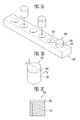
- FIG. 3A is a perspective view of a closed interconnector.
- a pair of interconnectors 200 are provided to be respectively coupled to both ends of unit cells 100.
- a plurality of consecutive accommodating grooves, or recesses, 210 are formed in the body 240 of the interconnector 200.
- the accommodating groove 210 is formed to have a suitable shape and size (e.g., diameter) so that the exposed portion 100a of the unit cell 100 can be inserted into the accommodating groove 210 with a suitable small looseness.
- a conductive connection member 230 is provided at a bottom surface of one accommodating groove 210 to be extended to a bottom surface of another accommodating groove 210 adjacent to the one accommodating groove 210.
- the conductive connection member 230 does not connect the bottom surfaces of all the accommodating grooves 210 to one another but connects the bottom surfaces of a pair of accommodating grooves 210 to each other.
- the conductive connection member 230 may be formed of a single metal such as nickel, copper or silver with high conductivity, an alloy thereof, or an alloy thereof with a heterogeneous metal.
- FIG. 3B is a perspective view of the closed projection 220.
- FIG. 3C is a sectional view of the projection 220 taken along line in FIG. 3B .
- the projection 220 is formed to have the shape with a cross section substantially similar or identical to the accommodating groove 210 so that it can be inserted into the accommodating groove 210 with a suitable small looseness.
- one portion of the projection 220 is inserted into the interior of the accommodating groove 210, and the other portion of the projection 220 is exposed.
- a conductive coating portion 221 is formed as an outer surface (e.g., circumferential surface) of the projection 220.
- An end portion of the projection 220, which is not inserted into the accommodating groove 210, may be finished with an insulating member so that the conductive coating portion 221 and an internal current collector (not shown) in the unit cell 100 are not short circuited.
- the conductive coating portion 221 may be formed of a single metal such as nickel, copper or silver with high conductivity, an alloy thereof, or an alloy thereof with a heterogeneous metal.
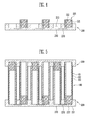
- FIG. 4 is a sectional view of a closed serial interconnector.
- One projection 220 is inserted into every other one of the accommodating grooves 210 so as to constitute the serial interconnector 200.
- the conductive coating portion 221 comes in contact with the conductive connection portion 230 described above so that they are electrically connected to each other.
- FIG. 5 is a sectional view showing the connection structure of a closed serial unit cell bundle.
- a pair of interconnectors 200 are aligned so that accommodating grooves 210 and projections 220 face each other.
- a plurality of unit cells 100 are coupled to the pair of interconnectors 200 so that the exposed portion 100a (see FIG. 1 ) of each of the unit cells 100 is inserted into the accommodating groove 210, and the extended portion 100b (see FIG. 1 ) of each of the unit cells 100 accommodates the projection 220.
- the unit cell 100 is provided with current collectors with various shapes at the interior and/or exterior thereof so as to collect current in the operation of the fuel cell.
- the internal current collector provided to the interior of the unit cell 100 is connected to the conductive connection member 230.
- the external current collector provided to the exterior of the unit cell 100 is connected to the conductive coating portion 221 of the projection 220 through a lower end of the extended portion 100b. In such a manner, the unit cells 100 are connected in series as many as required in the bundle.
- the second embodiment relates to a case where an opened serial interconnector is used.
- the opened interconnector described in this embodiment may be used to be properly combined with the closed interconnection described above.
- a unit cell 100 of the second embodiment is identical to that of the first embodiment.
- other components will be described.
- FIG. 6A is a perspective view of an opened projection 220a.
- FIG. 6B is a longitudinal sectional view showing another embodiment of the opened projection 220b.
- the projection 220a is formed in a cylindrical shape, and a through-hole that passes through in the centre axis direction of the projection 220a is formed in the projection 220a.
- a lower portion of the projection 220a may be formed only with a conductive coating portion 221a as shown in FIG. 6A .
- a projection 220b includes a conductive coating portion 221b formed only at a lower portion of an insulating portion 222b.
- FIG. 6C is a sectional view of an opened interconnector for connecting unit cells in series.
- a through-hole that passes through a body portion 240a of the interconnector 200a is formed at the bottom surface of an accommodating groove 210a.
- the size (e.g., diameter) of the through-hole is formed smaller than that of the accommodating groove 210.
- a conductive connection member 230 is formed so that bottom portions of adjacent accommodating grooves 210a are electrically connected to each other. In this embodiment, the conductive connection members 230 are formed between all the adjacent accommodating grooves 210a.
- FIG. 7 is a sectional view showing a state that unit cells 100 connected in series are coupled to opened interconnectors 200a.
- a pair of interconnectors 200a are aligned so that accommodating grooves 210a and projections 220a face each other.
- the unit cells 100 are coupled to the pair of interconnectors 200a so that the exposed portion 100a (see FIG. 1 ) of each of the unit cells 100 is inserted into the accommodating groove 210a, and the extended portion 100b (see FIG. 1 ) of each of the unit cells 100 accommodates the projection 220a (see FIG. 6 ).
- an internal current collector provided to the interior of the unit cell 100 is connected to the conductive connection member 230.
- An external current collector provided to the exterior of the unit cell 100 is connected to the conductive coating portion 221a of the projection 220a through a lower end of the extended portion 100b. In such a manner, the unit cells 100 are connected in series as many as required in the bundle.
- the third embodiment relates to a parallel interconnector and a unit cell bundle having the same.
- a closed interconnector has been used in this embodiment, the opened interconnector described above may be used in the same manner.
- Unit cells 100 and projections 220 of this embodiment are identical to those of the first embodiment, respectively. However, in a case where the opened interconnector is used, the projection 220 is changed to the projection 220a of the second embodiment.
- FIG. 8 is a sectional view showing the configuration of a closed interconnector for connecting unit cells in parallel.
- a pair of interconnectors 200b are provided to be respectively coupled to both ends of the unit cells 100.
- Accommodating grooves 210 substantially similar or identical to those of the first embodiment are formed in each of the interconnector 200b.
- conductive connection members 230 are formed between all the adjacent accommodating grooves 210 so that bottom surfaces of the accommodating grooves 210 are electrically connected to one another.
- the projections 220 are not inserted into all the accommodating grooves 210 of one interconnector 200b, the projections 220 are inserted into all the accommodating grooves 210 of another interconnector 200b as shown in FIG. 8 .
- the insertion direction of the projections 220 is substantially similar or identical to those of the first and second embodiments.
- FIG. 9 is a sectional view showing a state that unit cells connected in parallel are coupled to closed interconnectors.
- a pair of interconnectors 200b are aligned to face each other.
- a plurality of the unit cells 100 are coupled to the pair of interconnectors 200b so that the exposed portion 100a (see FIG. 1 ) of each of the unit cells 100 is inserted into the accommodating groove 210, and the extended portion 100b (see FIG. 1 ) of each of the unit cells 100 accommodates the projection 220.
- an internal current collector provided to the interior of the unit cell 100 is connected to the conductive connection member 230.
- An external current collector provided to the exterior of the unit cell 100 is connected to the conductive coating portion 221 of the projection 220 through a lower end of the extended portion 100b (see FIG. 1 ). In such a manner, the unit cells 100 are connected in parallel as many as required in the bundle.
Abstract
A bundle-type interconnector is used in a fuel cell. In one embodiment, a bundle-type interconnector includes an interconnector and a plurality of projections. A plurality of accommodating grooves are formed in the interconnector, and the interconnector has conductive connection members that electrically connect the interiors of the accommodating grooves. Each of the projections is inserted into the accommodating groove, and a conductive material is coated on an outer surface of each of the projections. Accordingly, a cell bundle can be configured regardless of opened and closed interconnectors and the connection structure thereof, and maintenance and repair can be easily performed during the operation of the fuel cell.
Description
- The present invention relates to an interconnector and a fuel cell having the same, particulary to a bundle-type interconnector.
- Since the voltage of a unit cell by itself is relatively low in a fuel cell, a plurality of unit cells are connected in parallel and/or series to one another so as to obtain desired current and voltage. A set of a plurality of unit cells is referred to as a stack.
- If unit cells are independently managed, the operation of the entire fuel cell system is stopped, and maintenance and repair are necessarily performed with respect to the entire stack even when only a portion of the unit cells has a defect.
- Aspects of embodiments according to the present invention are directed toward interconnectors that constitute a cell bundle and a cell bundle structure connected through the interconnectors.
- According to an embodiment of the present invention, there is provided a bundle-type interconnector including an interconnector and a plurality of projections. A plurality of accommodating grooves are formed in the interconnector, and the interconnector has conductive connection members that electrically connect interiors of the accommodating grooves. Each of the projections is inserted into a corresponding one of the accommodating grooves, and a conductive material is formed on an outer surface of each of the projections.
- The conductive connection member may electrically connect a pair of the accommodating grooves to each other.
- The conductive connection member may electrically connect adjacent ones of the accommodating grooves.
- The conductive connection member may pass through a portion of the interconnector to electrically connect bottoms of adjacent ones of the accommodating grooves.
- The interconnector may have a through-hole that passes through a portion of the interconnector at a bottom surface of one of the accommodating grooves, and the projection may have a through-hole that passes through a portion of the projection in a center axis direction of the projection.
- One end of the projection, exposed outside of the accommodating groove, may be finished with an insulating material.
- The conductive connection member may include at least one selected from the group consisting of nickel, copper, silver, and an alloy thereof.
- The conductive material coated on the projection may include at least one selected from the group consisting of nickel, copper, silver, and an alloy thereof.
- According to an embodiment of the present invention, there is provided a fuel cell including a unit cell bundle. The unit cell bundle includes a pair of interconnectors, a plurality of projections and a plurality of unit cells.
- A plurality of accommodating grooves are formed in each of the pair of interconnectors, and each of the pair of interconnectors has conductive connection members at bottom surfaces of the accommodating grooves to electrically connect adjacent ones of the accommodating grooves to each other. A conductive material is coated on an outer surface of each of the projections, and the projections are inserted into every other one of the accommodating grooves. The unit cells have a tubular shape, each of the unit cells including a first electrode layer, an electrolytic layer and a second electrode layer stacked in a radial direction from a centre axis thereof. An exposed portion in which a portion of the first electrode layer is exposed is located at one end of each of the unit cells, and an extended portion formed by extending the second electrode layer beyond the first electrode layer is at the other end of each of the unit cells. The exposed portion is inserted into a corresponding one of the accommodating grooves, and the extended portion accommodates a corresponding one of the projections so that the unit cells are electrically connected in series to one another.
- A through-hole that passes through a portion of the interconnector may be formed at the bottom surface of one of the accommodating grooves, and a through-hole that passes through the projection in a center axis direction of the projection may be formed in the projection.
- One end of the projection, inserted into a corresponding one of the unit cells, may be finished with insulating material.
- According to another embodiment of the present invention, there is provided a fuel cell including a unit cell bundle. The unit cell bundle includes a pair of interconnectors, a plurality of projections and a plurality of unit cells.
- A plurality of accommodating grooves are formed in each of the pair of interconnectors, and each of the pair of interconnectors has conductive connection members that electrically connect interiors of the accommodating grooves. A conductive material is coated on an outer surface of each of the projections, and the projections are inserted into all of the accommodating grooves of one of the interconnectors. The unit cells have a tubular shape, each of the unit cells including a first electrode layer, an electrolytic layer and a second electrode layer stacked in a radial direction from a center axis thereof. An exposed portion in which a portion of the first electrode layer is exposed is located at one end of each of the unit cells, and an extended portion formed by extending the second electrode layer beyond the first electrode layer is at the other end of each of the unit cells. The exposed portion is inserted into a corresponding one of the accommodating grooves, and the extended portion accommodates a corresponding one of the projections so that the unit cells are electrically connected in parallel to one another.
- The conductive connection member may pass through a portion of the interconnector to electrically connect bottoms of adjacent ones of the accommodating grooves.
- A through-hole that passes through a portion of the interconnector may be formed at the bottom surface of the accommodating groove, and a through-hole that passes through the projection in a center axis direction of the projection may be formed in the projection.
- One end of the projection, inserted into the unit cell, may be finished with an insulating material.
- As described above, according to embodiments of the present invention, a cell bundle having cells connected in parallel and/or series can be easily configured.
- Also, a prompt action on a cell bundle having a defect can be taken during the operation of the fuel cell.
- That is, a cell bundle can be configured regardless of opened and closed interconnectors and the connection structure thereof, and maintenance and repair can be easily performed during the operation of the fuel cell.
- The accompanying drawings, together with the specification, illustrate exemplary embodiments of the present invention, and, together with the description, serve to explain the principles of the present invention.
-
FIG. 1 is a longitudinal sectional view of a unit cell. -
FIG. 2 is a cross-sectional view of the unit cell. -
FIG. 3A is a perspective view showing the configuration of an interconnector for connecting unit cells in series. -
FIG. 3B is a perspective view of a closed projection. -
FIG. 3C is a longitudinal sectional view of the projection taken along the line V-V' inFIG. 3B . -
FIG. 4 is a sectional view showing the configuration of the interconnector for connecting unit cells in series. -
FIG. 5 is a sectional view showing a state that unit cells connected in series are coupled to interconnectors. -
FIG. 6A is a perspective view of an opened projection. -
FIG. 6B is a longitudinal sectional view showing another embodiment of the opened projection. -
FIG. 6C is a sectional view of an opened interconnector for connecting unit cells in series. -
FIG. 7 is a sectional view showing a state that unit cells connected in series are coupled to opened interconnectors. -
FIG. 8 is a sectional view showing the configuration of a closed interconnector for connecting unit cells in parallel. -
FIG. 9 is a sectional view showing a state that unit cells connected in parallel are coupled to closed interconnectors. - Hereinafter, a "tubular" unit cell refers to a cell-shaped unit cell formed in the shape of a hollow pipe regardless of the shape of a cross section thereof. That is, the shape of a cross section with respect to the central axis of the tubular unit cell may be formed in various shapes such as a circle and a polygon.
- Unit cells are also referred to herein as fuel cell elements.
- The first embodiment relates to a case where a serial interconnector is used. The serial interconnector of the first embodiment may be combined with an opened (or open-ended) interconnector which will be described in a second embodiment. However, in this embodiment, a closed (or close-ended) interconnector will be described. Thereafter, other types of interconnectors will be described.
- A
unit cell 100 will be described with reference toFIG. 1. FIG. 1 is a longitudinal sectional view of a tubular unit cell. - The unit cell, or fuel cell element, 100 is a component that receives fuel reformed from a fuel converter (not shown) to produce electricity through an oxidation reaction. The
unit cell 100 is formed in a tubular shape as shown inFIGS. 1 and 2 . Thetubular unit cell 100 has a structure in which afirst electrode layer 101, an electrolytic (electrolyte)layer 102 and asecond electrode layer 103 are stacked in a radial direction from the centre axis thereof. A plurality ofunit cells 100 ofFIG. 1 are provided as many as desired to be configured as a bundle. An exposedportion 100a having thefirst electrode layer 101 exposed therethrough is formed at one end of theunit cell 100, and anextended portion 100b formed by extending thesecond electrode layer 103 is formed at the other end of theunit cell 100. - The
unit cell 100 is formed as an anode-supported or cathode-supported unit cell according to its application. In this embodiment, theunit cell 100 may be the anode-supported or cathode-supported unit cell. That is, thefirst electrode layer 101 may be an anode or cathode. - In one embodiment, the cathode is formed of a pure electron conductor or mixed conductor such as a LaMnO3-based or LaCoO3-based material, which has high ion and electron conductivity, stability under an oxygen atmosphere, and no chemical reaction with the electrolytic layer which will be described later. The electrolytic layer is a portion that serves as a path along which oxygen ions produced through the cathode and hydrogen ions produced through the anode, which will be described later, are moved. The electrolytic layer is made of a ceramic material having a compactness with which gas does not penetrate the ceramic material. In one embodiment, yttria stabilized zirconia (hereinafter, referred to as YSZ) obtained by adding a small amount of Y2O3 to ZrO2 is used as the electrolytic layer. The YSZ is formed into a structure having high ion conductivity under oxidation and reduction atmospheres as well as chemical and physical stability. The anode is a portion to which hydrogen gas that is fuel of the fuel cell is supplied. The anode is basically made of a ceramic material such as YSZ. In one embodiment, a metal ceramic complex (cermet) such as NiO-8YSZ or Ni-8YSZ is used as the anode. Here, the metal ceramic complex (cermet) is economical and has suitable stability under a high-temperature reduction atmosphere.
- An
interconnector 200 will be described with reference toFIG. 3A. FIG. 3A is a perspective view of a closed interconnector. - A pair of
interconnectors 200 are provided to be respectively coupled to both ends ofunit cells 100. A plurality of consecutive accommodating grooves, or recesses, 210 are formed in thebody 240 of theinterconnector 200. Theaccommodating groove 210 is formed to have a suitable shape and size (e.g., diameter) so that the exposedportion 100a of theunit cell 100 can be inserted into theaccommodating groove 210 with a suitable small looseness. - As shown in
FIG. 4 , aconductive connection member 230 is provided at a bottom surface of oneaccommodating groove 210 to be extended to a bottom surface of anotheraccommodating groove 210 adjacent to the oneaccommodating groove 210. Here, theconductive connection member 230 does not connect the bottom surfaces of all theaccommodating grooves 210 to one another but connects the bottom surfaces of a pair ofaccommodating grooves 210 to each other. Theconductive connection member 230 may be formed of a single metal such as nickel, copper or silver with high conductivity, an alloy thereof, or an alloy thereof with a heterogeneous metal. - A
projection 220 will be described with reference toFIGS. 3B and 3C. FIG. 3B is a perspective view of theclosed projection 220.FIG. 3C is a sectional view of theprojection 220 taken along line inFIG. 3B . - The
projection 220 is formed to have the shape with a cross section substantially similar or identical to theaccommodating groove 210 so that it can be inserted into theaccommodating groove 210 with a suitable small looseness. Here, one portion of theprojection 220 is inserted into the interior of theaccommodating groove 210, and the other portion of theprojection 220 is exposed. Aconductive coating portion 221 is formed as an outer surface (e.g., circumferential surface) of theprojection 220. An end portion of theprojection 220, which is not inserted into theaccommodating groove 210, may be finished with an insulating member so that theconductive coating portion 221 and an internal current collector (not shown) in theunit cell 100 are not short circuited. In one embodiment, theconductive coating portion 221 may be formed of a single metal such as nickel, copper or silver with high conductivity, an alloy thereof, or an alloy thereof with a heterogeneous metal. - The connection structure between the interconnector 200 and the
projections 220 will be described with reference toFIG. 4. FIG. 4 is a sectional view of a closed serial interconnector. Oneprojection 220 is inserted into every other one of theaccommodating grooves 210 so as to constitute theserial interconnector 200. InFIG. 4 , theconductive coating portion 221 comes in contact with theconductive connection portion 230 described above so that they are electrically connected to each other. - The connection structure of a unit cell bundle will be described with reference to
FIG. 5. FIG. 5 is a sectional view showing the connection structure of a closed serial unit cell bundle. - A pair of
interconnectors 200 are aligned so thataccommodating grooves 210 andprojections 220 face each other. A plurality ofunit cells 100 are coupled to the pair ofinterconnectors 200 so that the exposedportion 100a (seeFIG. 1 ) of each of theunit cells 100 is inserted into theaccommodating groove 210, and theextended portion 100b (seeFIG. 1 ) of each of theunit cells 100 accommodates theprojection 220. - Further, the
unit cell 100 is provided with current collectors with various shapes at the interior and/or exterior thereof so as to collect current in the operation of the fuel cell. In one embodiment, the internal current collector provided to the interior of theunit cell 100 is connected to theconductive connection member 230. The external current collector provided to the exterior of theunit cell 100 is connected to theconductive coating portion 221 of theprojection 220 through a lower end of theextended portion 100b. In such a manner, theunit cells 100 are connected in series as many as required in the bundle. - The second embodiment relates to a case where an opened serial interconnector is used. The opened interconnector described in this embodiment may be used to be properly combined with the closed interconnection described above. Here, a
unit cell 100 of the second embodiment is identical to that of the first embodiment. Hereinafter, other components will be described. - Projections according to other embodiments will be described with reference to
FIGS. 6A and 6B. FIG. 6A is a perspective view of an openedprojection 220a.FIG. 6B is a longitudinal sectional view showing another embodiment of the openedprojection 220b. - The
projection 220a is formed in a cylindrical shape, and a through-hole that passes through in the centre axis direction of theprojection 220a is formed in theprojection 220a. A lower portion of theprojection 220a may be formed only with aconductive coating portion 221a as shown inFIG. 6A . Further, as shown inFIG. 6B , aprojection 220b includes aconductive coating portion 221b formed only at a lower portion of an insulatingportion 222b. - The connection structure between an interconnector 200a and the
projections 220a will be described with reference toFIG. 6C. FIG. 6C is a sectional view of an opened interconnector for connecting unit cells in series. A through-hole that passes through abody portion 240a of theinterconnector 200a is formed at the bottom surface of anaccommodating groove 210a. Here, the size (e.g., diameter) of the through-hole is formed smaller than that of theaccommodating groove 210. Aconductive connection member 230 is formed so that bottom portions of adjacentaccommodating grooves 210a are electrically connected to each other. In this embodiment, theconductive connection members 230 are formed between all the adjacentaccommodating grooves 210a. - The connection structure of a unit cell bundle according to an embodiment will be described with reference to
FIG. 7. FIG. 7 is a sectional view showing a state thatunit cells 100 connected in series are coupled to openedinterconnectors 200a. - A pair of
interconnectors 200a are aligned so thataccommodating grooves 210a andprojections 220a face each other. Theunit cells 100 are coupled to the pair ofinterconnectors 200a so that the exposedportion 100a (seeFIG. 1 ) of each of theunit cells 100 is inserted into theaccommodating groove 210a, and theextended portion 100b (seeFIG. 1 ) of each of theunit cells 100 accommodates theprojection 220a (seeFIG. 6 ). - Like the first embodiment, an internal current collector provided to the interior of the
unit cell 100 is connected to theconductive connection member 230. An external current collector provided to the exterior of theunit cell 100 is connected to theconductive coating portion 221a of theprojection 220a through a lower end of theextended portion 100b. In such a manner, theunit cells 100 are connected in series as many as required in the bundle. - The third embodiment relates to a parallel interconnector and a unit cell bundle having the same. Although a closed interconnector has been used in this embodiment, the opened interconnector described above may be used in the same manner.
-
Unit cells 100 andprojections 220 of this embodiment are identical to those of the first embodiment, respectively. However, in a case where the opened interconnector is used, theprojection 220 is changed to theprojection 220a of the second embodiment. - An interconnector 200b will be described with reference to
FIG. 8. FIG. 8 is a sectional view showing the configuration of a closed interconnector for connecting unit cells in parallel. - A pair of
interconnectors 200b are provided to be respectively coupled to both ends of theunit cells 100. Accommodatinggrooves 210 substantially similar or identical to those of the first embodiment are formed in each of the interconnector 200b. Here,conductive connection members 230 are formed between all the adjacentaccommodating grooves 210 so that bottom surfaces of theaccommodating grooves 210 are electrically connected to one another. While, theprojections 220 are not inserted into all theaccommodating grooves 210 of oneinterconnector 200b, theprojections 220 are inserted into all theaccommodating grooves 210 of another interconnector 200b as shown inFIG. 8 . The insertion direction of theprojections 220 is substantially similar or identical to those of the first and second embodiments. - The connection structure between the
unit cells 100 and theinterconnectors 200b will be described with reference toFIG. 9. FIG. 9 is a sectional view showing a state that unit cells connected in parallel are coupled to closed interconnectors. - A pair of
interconnectors 200b are aligned to face each other. A plurality of theunit cells 100 are coupled to the pair ofinterconnectors 200b so that the exposedportion 100a (seeFIG. 1 ) of each of theunit cells 100 is inserted into theaccommodating groove 210, and theextended portion 100b (seeFIG. 1 ) of each of theunit cells 100 accommodates theprojection 220. Like the first embodiment, an internal current collector provided to the interior of theunit cell 100 is connected to theconductive connection member 230. An external current collector provided to the exterior of theunit cell 100 is connected to theconductive coating portion 221 of theprojection 220 through a lower end of theextended portion 100b (seeFIG. 1 ). In such a manner, theunit cells 100 are connected in parallel as many as required in the bundle. - While the present invention has been described in connection with certain exemplary embodiments, it is to be understood that the invention is not limited to the disclosed embodiments, but, on the contrary, is intended to cover various modifications and equivalent arrangements included within the scope of the appended claims.
Claims (15)
- An interconnector (200, 200a, 200b) for connecting a plurality of fuel cell elements, comprising:a body (240, 240a) having a plurality of accommodating recesses (210, 210a) formed therein, the body having conductive connection members (230) that electrically connect interiors of the accommodating recesses; anda plurality of projections (220, 220a, 220b) inserted into corresponding ones of the accommodating recesses, each of the projections having a conductive material (221, 221a, 221b) formed on an outer surface thereof.
- The interconnector according to claim 1, wherein the conductive connection member (230) electrically connects a pair of the accommodating recesses to each other.
- The interconnector according to claim 1 or 2, wherein the conductive connection member (230) electrically connects adjacent ones of the accommodating recesses.
- The interconnector according to claim 3, wherein the conductive connection member passes through the body to electrically connect bottoms of adjacent ones of the accommodating recesses.
- The interconnector according to any one of the preceding claims, wherein the body has a through-hole that passes through the body at a bottom surface of one of the accommodating recesses, and the projection has a through-hole for alignment with the through hole in the body.
- The interconnector according to any one of the preceding claims, comprising an insulating material on one end of the projection.
- The interconnector according to any one of the preceding claims, wherein the conductive connection member comprises at least one selected from the group consisting of nickel, copper, silver, and an alloy thereof.
- The interconnector according to any one of the preceding claims, wherein the conductive material coated on the projection comprises at least one selected from the group consisting of nickel, copper, silver, and an alloy thereof.
- A fuel cell comprising a bundle of fuel cell elements,
wherein the bundle comprises:a pair of interconnectors each according to any one of the preceding claims,wherein the projections are inserted into every other one of the accommodating recesses; anda plurality of fuel cell elements disposed between the interconnectors. - The fuel cell according to claim 9, wherein each of the fuel cell elements are tubular and comprise a first electrode layer, an electrolytic layer and a second electrode layer stacked in a radial direction from a center axis thereof, wherein an exposed portion of the first electrode layer is located at one end of each of the fuel cell elements, and an extended portion of the second electrode layer extending beyond the first electrode layer is at the other end of each of the fuel cell elements,
wherein the exposed portion is inserted into a corresponding one of the accommodating recesses, and the extended portion accommodates a corresponding one of the projections so that the plurality of fuel cell elements are electrically connected in series to one another. - A fuel cell comprising a bundle of fuel cell elements, wherein the bundle comprises:a pair of interconnectors each according to any one of claims 1 to 8, wherein the projections are inserted into all the accommodating recesses of one of the interconnectors; anda plurality of fuel cell elements disposed between the interconnectors.
- The fuel cell according to claim 11, wherein each of the fuel cell elements are tubular and comprise a first electrode layer, an electrolytic layer and a second electrode layer stacked in a radial direction from a center axis thereof, wherein an exposed portion of the first electrode layer is located at one end of each of the unit cells, and an extended portion of the second electrode layer extending beyond the first electrode layer is at the other end of each of the unit cells,
wherein each exposed portion is inserted into a corresponding one of the accommodating recesses and each extended portion accommodates a corresponding one of the projections so that the plurality of unit cells are electrically connected in parallel to one another. - The fuel cell according to any one of claims 9 to 12, wherein the conductive connection member is arranged to electrically connect the conductive material of adjacent ones of the projections to one another or to connect the conductive material of one of the projections to the first electrode layer (101) of the adjacent fuel cell element or to connect the first electrode layers (101) of the adjacent fuel cell elements together.
- The fuel cell according to any one of claims 9 to 13, wherein through-holes in the body are aligned with through-holes in the projections.
- The fuel cell according to any one of claims 9 to 14, wherein the insulating material at one end of the projection is arranged to butt up against the first electrode layer (101) and the electrolytic layer (102) to insulate the layers from the conductive material (221).
Applications Claiming Priority (1)
| Application Number | Priority Date | Filing Date | Title |
|---|---|---|---|
| KR1020100069034A KR101178675B1 (en) | 2010-07-16 | 2010-07-16 | Bundle-type interconnector and the fuel cell having the same |
Publications (1)
| Publication Number | Publication Date |
|---|---|
| EP2408049A1 true EP2408049A1 (en) | 2012-01-18 |
Family
ID=44503598
Family Applications (1)
| Application Number | Title | Priority Date | Filing Date |
|---|---|---|---|
| EP11173833A Withdrawn EP2408049A1 (en) | 2010-07-16 | 2011-07-13 | Interconnector and fuel cell having the same |
Country Status (3)
| Country | Link |
|---|---|
| US (1) | US20120015277A1 (en) |
| EP (1) | EP2408049A1 (en) |
| KR (1) | KR101178675B1 (en) |
Families Citing this family (4)
| Publication number | Priority date | Publication date | Assignee | Title |
|---|---|---|---|---|
| JP6463828B2 (en) * | 2016-12-27 | 2019-02-06 | コリア インスティチュート オブ セラミック エンジニアリング アンド テクノロジー | Fuel cell including unit cell module that can be replaced individually during operation and stack module for high-temperature water electrolysis |
| KR102017328B1 (en) | 2016-12-27 | 2019-09-03 | 한국세라믹기술원 | Stack module for fuel battery and high temperature electrolysis comprising cell battery modules which can individually change under an operation |
| KR102200468B1 (en) * | 2019-12-17 | 2021-01-08 | (주)에프씨아이 | Detachable molten carbonate fuel cell module |
| CN114824403A (en) * | 2021-01-19 | 2022-07-29 | 中国科学院上海硅酸盐研究所 | Module combined reversible battery stack with high fault tolerance |
Citations (4)
| Publication number | Priority date | Publication date | Assignee | Title |
|---|---|---|---|---|
| US20030082434A1 (en) * | 2001-10-19 | 2003-05-01 | Conghua Wang | Solid oxide fuel cells and interconnectors |
| US20040053104A1 (en) * | 2002-09-12 | 2004-03-18 | Novkov Donald James | Current feeders for electrochemical cell stacks |
| US20060228615A1 (en) * | 2005-04-11 | 2006-10-12 | Armstrong Timothy R | Stack configurations for tubular solid oxide fuel cells |
| US20080096086A1 (en) * | 2006-10-19 | 2008-04-24 | Honda Motor Co., Ltd. | Fuel cell and fuel cell stack |
Family Cites Families (1)
| Publication number | Priority date | Publication date | Assignee | Title |
|---|---|---|---|---|
| JP4240530B2 (en) * | 2006-09-15 | 2009-03-18 | Toto株式会社 | Fuel cell body, fuel cell unit, fuel cell stack, and fuel cell including them |
-
2010
- 2010-07-16 KR KR1020100069034A patent/KR101178675B1/en not_active IP Right Cessation
-
2011
- 2011-06-24 US US13/168,923 patent/US20120015277A1/en not_active Abandoned
- 2011-07-13 EP EP11173833A patent/EP2408049A1/en not_active Withdrawn
Patent Citations (4)
| Publication number | Priority date | Publication date | Assignee | Title |
|---|---|---|---|---|
| US20030082434A1 (en) * | 2001-10-19 | 2003-05-01 | Conghua Wang | Solid oxide fuel cells and interconnectors |
| US20040053104A1 (en) * | 2002-09-12 | 2004-03-18 | Novkov Donald James | Current feeders for electrochemical cell stacks |
| US20060228615A1 (en) * | 2005-04-11 | 2006-10-12 | Armstrong Timothy R | Stack configurations for tubular solid oxide fuel cells |
| US20080096086A1 (en) * | 2006-10-19 | 2008-04-24 | Honda Motor Co., Ltd. | Fuel cell and fuel cell stack |
Also Published As
| Publication number | Publication date |
|---|---|
| KR20120008272A (en) | 2012-01-30 |
| US20120015277A1 (en) | 2012-01-19 |
| KR101178675B1 (en) | 2012-08-30 |
Similar Documents
| Publication | Publication Date | Title |
|---|---|---|
| EP2296212B1 (en) | A Cell Module for a Solid Oxide Fuel Cell | |
| US20070148523A1 (en) | Interconnection of bundled solid oxide fuel cells | |
| JP2009521793A (en) | Solid oxide fuel cell and stack configuration | |
| JP2008542977A (en) | Stack configuration for tubular solid oxide fuel cells | |
| US20080063916A1 (en) | Electrolytic/fuel cell bundles and systems including a current collector in communication with an electrode thereof, methods for generating electricity and/or performing electrolysis using the same | |
| KR101199175B1 (en) | Solid Oxide Fuel Cell | |
| US20100183938A1 (en) | Fuel cell | |
| EP2408049A1 (en) | Interconnector and fuel cell having the same | |
| US8835072B2 (en) | Solid oxide fuel cell stacks and fuel cell module having the same | |
| EP2006944A9 (en) | Solid oxide fuel cell | |
| US8895205B2 (en) | Solid oxide fuel cell comprising a coated wire current collector | |
| JP6773472B2 (en) | Electrochemical reaction unit and electrochemical reaction cell stack | |
| US9190672B2 (en) | Tubular solid oxide fuel cell including external current collector with plurality of connection portions | |
| US20130045435A1 (en) | Solid oxide fuel cell stack | |
| US9005845B2 (en) | Solid oxide fuel cell and manufacturing method thereof | |
| US9508996B2 (en) | Connecting material for a tubular solid oxide fuel cell, and tubular solid oxide fuel cell stack including same | |
| US20220140380A1 (en) | Cell stack device, module, and module housing device | |
| JP2018181568A (en) | Current collecting member-electrochemical reaction single cell composite, and electrochemical reaction cell stack | |
| JP6878257B2 (en) | Current collector-electrochemical reaction single cell complex and electrochemical reaction cell stack | |
| US20120015276A1 (en) | Solid oxide fuel cell and fuel cell stack | |
| JP6777473B2 (en) | Electrochemical reaction unit and electrochemical reaction cell stack | |
| US8951691B2 (en) | Solid oxide fuel cell stack | |
| JP2014191992A (en) | Method for manufacturing solid oxide fuel battery | |
| JP2017045601A (en) | Solid oxide fuel cell stack and solid oxide fuel cell module | |
| US20120237852A1 (en) | Solid oxide fuel cell |
Legal Events
| Date | Code | Title | Description |
|---|---|---|---|
| AK | Designated contracting states |
Kind code of ref document: A1 Designated state(s): AL AT BE BG CH CY CZ DE DK EE ES FI FR GB GR HR HU IE IS IT LI LT LU LV MC MK MT NL NO PL PT RO RS SE SI SK SM TR |
|
| AX | Request for extension of the european patent |
Extension state: BA ME |
|
| PUAI | Public reference made under article 153(3) epc to a published international application that has entered the european phase |
Free format text: ORIGINAL CODE: 0009012 |
|
| 17P | Request for examination filed |
Effective date: 20120629 |
|
| 17Q | First examination report despatched |
Effective date: 20120927 |
|
| STAA | Information on the status of an ep patent application or granted ep patent |
Free format text: STATUS: THE APPLICATION IS DEEMED TO BE WITHDRAWN |
|
| 18D | Application deemed to be withdrawn |
Effective date: 20130913 |