EP2407737B1 - Refrigerator - Google Patents
Refrigerator Download PDFInfo
- Publication number
- EP2407737B1 EP2407737B1 EP11173607.0A EP11173607A EP2407737B1 EP 2407737 B1 EP2407737 B1 EP 2407737B1 EP 11173607 A EP11173607 A EP 11173607A EP 2407737 B1 EP2407737 B1 EP 2407737B1
- Authority
- EP
- European Patent Office
- Prior art keywords
- water supply
- water
- supply unit
- refrigerator
- supplied
- Prior art date
- Legal status (The legal status is an assumption and is not a legal conclusion. Google has not performed a legal analysis and makes no representation as to the accuracy of the status listed.)
- Not-in-force
Links
Images





Classifications
-
- F—MECHANICAL ENGINEERING; LIGHTING; HEATING; WEAPONS; BLASTING
- F25—REFRIGERATION OR COOLING; COMBINED HEATING AND REFRIGERATION SYSTEMS; HEAT PUMP SYSTEMS; MANUFACTURE OR STORAGE OF ICE; LIQUEFACTION SOLIDIFICATION OF GASES
- F25C—PRODUCING, WORKING OR HANDLING ICE
- F25C1/00—Producing ice
- F25C1/04—Producing ice by using stationary moulds
-
- F—MECHANICAL ENGINEERING; LIGHTING; HEATING; WEAPONS; BLASTING
- F25—REFRIGERATION OR COOLING; COMBINED HEATING AND REFRIGERATION SYSTEMS; HEAT PUMP SYSTEMS; MANUFACTURE OR STORAGE OF ICE; LIQUEFACTION SOLIDIFICATION OF GASES
- F25D—REFRIGERATORS; COLD ROOMS; ICE-BOXES; COOLING OR FREEZING APPARATUS NOT OTHERWISE PROVIDED FOR
- F25D23/00—General constructional features
- F25D23/06—Walls
- F25D23/061—Walls with conduit means
-
- F—MECHANICAL ENGINEERING; LIGHTING; HEATING; WEAPONS; BLASTING
- F25—REFRIGERATION OR COOLING; COMBINED HEATING AND REFRIGERATION SYSTEMS; HEAT PUMP SYSTEMS; MANUFACTURE OR STORAGE OF ICE; LIQUEFACTION SOLIDIFICATION OF GASES
- F25C—PRODUCING, WORKING OR HANDLING ICE
- F25C2400/00—Auxiliary features or devices for producing, working or handling ice
- F25C2400/10—Refrigerator units
-
- F—MECHANICAL ENGINEERING; LIGHTING; HEATING; WEAPONS; BLASTING
- F25—REFRIGERATION OR COOLING; COMBINED HEATING AND REFRIGERATION SYSTEMS; HEAT PUMP SYSTEMS; MANUFACTURE OR STORAGE OF ICE; LIQUEFACTION SOLIDIFICATION OF GASES
- F25C—PRODUCING, WORKING OR HANDLING ICE
- F25C2400/00—Auxiliary features or devices for producing, working or handling ice
- F25C2400/14—Water supply
-
- F—MECHANICAL ENGINEERING; LIGHTING; HEATING; WEAPONS; BLASTING
- F25—REFRIGERATION OR COOLING; COMBINED HEATING AND REFRIGERATION SYSTEMS; HEAT PUMP SYSTEMS; MANUFACTURE OR STORAGE OF ICE; LIQUEFACTION SOLIDIFICATION OF GASES
- F25D—REFRIGERATORS; COLD ROOMS; ICE-BOXES; COOLING OR FREEZING APPARATUS NOT OTHERWISE PROVIDED FOR
- F25D23/00—General constructional features
- F25D23/12—Arrangements of compartments additional to cooling compartments; Combinations of refrigerators with other equipment, e.g. stove
- F25D23/126—Water cooler
-
- F—MECHANICAL ENGINEERING; LIGHTING; HEATING; WEAPONS; BLASTING
- F25—REFRIGERATION OR COOLING; COMBINED HEATING AND REFRIGERATION SYSTEMS; HEAT PUMP SYSTEMS; MANUFACTURE OR STORAGE OF ICE; LIQUEFACTION SOLIDIFICATION OF GASES
- F25D—REFRIGERATORS; COLD ROOMS; ICE-BOXES; COOLING OR FREEZING APPARATUS NOT OTHERWISE PROVIDED FOR
- F25D2323/00—General constructional features not provided for in other groups of this subclass
- F25D2323/122—General constructional features not provided for in other groups of this subclass the refrigerator is characterised by a water tank for the water/ice dispenser
Definitions
- a refrigerator is a home appliance providing a low-temperature storage that can be opened and closed by a door for storing foods at a low temperature.
- the refrigerator cools the inside of the storage space using cool air generated by heat-exchanging with a refrigerant that circulates a cooling cycle to store the foods in an optimum state.
- WO 2008/020707 discloses an ice tray assembly for a refrigerator.
- the ice tray assembly is installed in a door of a refrigerator.
- the ice tray assembly allows water to be supplied from a water container to an ice tray only when the door is closed.
- the ice tray assembly includes a valve for opening and closing a channel through which the water is supplied from the water container to the ice tray which is operated in cooperation with the operation of the door.
- JP 2005 257144 discloses a refrigerator with automatic ice making machine comprising a main tank part and auxiliary tank part mounted on the water supply container, a water supply port formed on a bottom part of the auxiliary tank part, an opening and closing valve for opening and closing the water supply port to naturally drop the water in the auxiliary tank part in supplying the water, and an air passage part for supplying air to the auxiliary tank part in supplying water, the water supply container having a double bottom structure formed by fitting the main tank container into a tank main body container, the inside of the main tank container is applied to the main tank part, and a double bottom structural part is applied to the auxiliary tank part.
- the water supply unit may be exposed to the outside of the refrigerator through the top surface of the cabinet.
- a side-by-side type refrigerator is described as an example in the embodiments.
- a blowing device may be disposed inside a freezing compartment.
- the present disclosure is not limited thereto. All types of refrigerator whether or not including a blowing device may incorporate the invention.
- the door 200 may include the freezing compartment door 210 and the refrigerating compartment door 220 which respectively open or close the refrigerating compartment 20 and the freezing compartment 10.
- the freezing compartment door 210 and the refrigerating compartment door 220 are rotatably disposed on the cabinet 100 to open or close the refrigerating compartment 20 and the freezing compartment 10.
- the ice making apparatus 300 may include the ice tray 310, the ice bank 320, and a frame 330.
- the frame 330 fixes the ice tray 310 or the ice tray 310 and the ice bank 320.
- the frame 330 is fixedly mounted on a top surface of the inside of the freezing compartment 10.
- the frame 330 is disposed on a position corresponding to that of the water supply unit mounting part 122. Also, the ice tray 310 may be easily accessible through the frame 330.
- the high-pressure water introduced through the connection tube 414 may be decreased in flow rate and pressure while being moved along an inner wall of the fill tank 410. Also, the water may be moved along the inclined bottom surface of the fill tank 410 and then discharged through the water discharge hole 416.
- Fig. 5 is a view illustrating a flow state of water in the water supply unit.
- the water introduced into the fill tank 410 is rotated along the inner surface of the fill tank 410 and moved downward along the bottom surface of the fill tank 410 inclined downward. Then, the water is introduced into the guide tube 412 through the water discharge hole 416 defined in the bottom surface of the fill tank 410.
- Fig. 8 is a sectional view illustrating a structure of an upper portion of a cabinet according to another embodiment.
- a cabinet 100 includes an outer case 120, an inner case 130, and an insulation material 140.
- a water supply unit mounting part 132 which is recessed upward is defined in a top surface of the inside of the inner case 130.
- the water supply unit case 620 may include a case body defining a space for receiving the fill tank 610 and a case cover 624 for covering an opened bottom surface of the case body 622.
- the case body 622 is fixedly mounted on the water supply unit mounting part 132.
- the case cover 624 may be openably disposed inside the storage space and exposed to a side of the inside of the refrigerator. In a state where the case cover 624 is closed, the case cover 624 may be flush with the inner case 130.
- a water supply unit 720 for supplying water into the ice maker 712 is disposed above the ice maker 712.
- the water supply unit 720 is connected to a water supply passage 440. Since the water supply unit 720 has the same inner structure as that of the water supply unit 400 according to the foregoing embodiments, their detailed description will be omitted.
- FIG. 10 is a side-sectional view of a refrigerator according to another embodiment.
- a refrigerator 3 includes a cabinet 50 defining a storage space and a door 60 for opening/closing the storage space.
- a cabinet 50 defining a storage space and a door 60 for opening/closing the storage space.
- an outer appearance of the refrigerator 2 is defined by the cabinet 50 and the door 60.
- the water supply passage 930 is disposed via the outside of the cabinet 70. As necessary, the water supply passage 930 may be disposed inside the cabinet 70. A pump 932 and a valve 934 for stably supplying water into the water supply passage 930 may be disposed on the water supply passage 930.
Landscapes
- Engineering & Computer Science (AREA)
- Physics & Mathematics (AREA)
- Mechanical Engineering (AREA)
- Thermal Sciences (AREA)
- General Engineering & Computer Science (AREA)
- Chemical & Material Sciences (AREA)
- Combustion & Propulsion (AREA)
- Devices That Are Associated With Refrigeration Equipment (AREA)
- Beverage Vending Machines With Cups, And Gas Or Electricity Vending Machines (AREA)
Description
- The invention relates to a refrigerator.
- A refrigerator is a home appliance providing a low-temperature storage that can be opened and closed by a door for storing foods at a low temperature. For this, the refrigerator cools the inside of the storage space using cool air generated by heat-exchanging with a refrigerant that circulates a cooling cycle to store the foods in an optimum state.
- The size of the refrigerator tends to increase more and more and multi-functions are provided to the refrigerator as dietary life changes and pursues high quality, and accordingly, refrigerators of various structures with consideration of user convenience and energy efficiency are brought to the market.
- Specifically, a refrigerator including an ice making apparatus in which water is automatically supplied to make ices is becoming popular these days. In this case, water within a water tank or a water supply source such as a water pipe is supplied into the ice making apparatus of the refrigerator to make ice. Here, when the water supplied into the ice making apparatus has a high pressure, the water may be spattered to tangle the stored ice with each other in the ice making apparatus. As a result, the ice-making performance and quality of the ice-making apparatus may be deteriorated.
-
US 2010/0083685 A1 discloses a refrigerator including a main body cabinet forming a storage compartment with a front opening, a door opening and closing the front opening of the storage compartment, and an ice making tray mounted to the door and making ice. The refrigerator includes a water supplying pipe which receives water from a water supplying source; a discharging pipe guide which includes a hollow part and is mounted to a through part penetrating from an outside region of the door to an upper side of the ice making tray; and a discharging pipe which includes a first end detachably connected to the water supplying pipe, and a second end disposed above the ice making tray after passing through the hollow part and detachably coupled to the door. -
US 5904054 discloses an apparatus for supplying an exact quantity of a water to an ice tray. The apparatus includes a first container having a same volume as the ice tray and being rotatably installed below the water tank, and a valve unit for opening and closing the water tank. A driving member for rotating the first container and at the same time, raising and lowering the valve unit is provided. A water supply member is installed in a partition wall which partitions off the freezing and refrigerating compartments. The water supply member flows water from an outlet pipe of a second container to the ice tray. At first, water is supplied to the first container, and then water supplied to the first container is supplied to the ice tray. -
GB 2282216 -
WO 2008/020707 discloses an ice tray assembly for a refrigerator. The ice tray assembly is installed in a door of a refrigerator. The ice tray assembly allows water to be supplied from a water container to an ice tray only when the door is closed. To this end, the ice tray assembly includes a valve for opening and closing a channel through which the water is supplied from the water container to the ice tray which is operated in cooperation with the operation of the door. -
JP 2005 257144 -
WO 2008/033000 discloses an ice making apparatus. A fluid passage guide is formed in a water supply unit to prevent water discharged from the water supply unit from being splashed to an external side of a tray. -
GB 2299657 -
US 6041607 discloses a refrigerator which can supply water from a household water supply system into an ice tray, or alternatively, can supply water from a separate water tank into the ice tray. The refrigerator has a housing having a refrigerating chamber, a freezing chamber, and an evaporator chamber which is disposed at a rear portion of the freezing chamber, an ice tray disposed in the freezing chamber, a motor assembly for rotating the ice tray when a liquid filled in the ice tray is frozen, a valve box installed on an upper surface of the housing for receiving the liquid from a household water supply system or from a liquid tank, a fluid path for guiding the liquid from the valve box to the ice tray, a rotating fan assembly for detecting an amount of the liquid flowed into the ice tray, a solenoid valve assembly for adjusting the amount of the liquid being supplied into the ice tray, and an electric control unit for operating the solenoid valve assembly based on an electric signal inputted from the rotating fan assembly. - According to the invention, there is provided a refrigerator as defined in
claim 1. This refrigerator comprises, in particular, an ice making apparatus which uses water supplied from a water supply source to make ice ; a cabinet defining a storage space which is opened or closed by a door; a water supply passage extending from a water supply source toward the ice making apparatus; and a water supply unit disposed above the ice making apparatus, the water supply unit having a sectional area greater than that of the water supply passage and being connected to the water supply passage to receive water supplied through the water supply passage. - The water supply unit may be mounted on an outer top surface of the cabinet.
- The water supply unit may be mounted to so that a top surface thereof is exposed to an outer case defining an outer appearance of the cabinet.
- The water supply unit may be buried into an insulation material filled into the cabinet.
- The water supply unit may be exposed to the outside of the refrigerator through the top surface of the cabinet.
- The water supply unit may be mounted inside the storage space.
- The water supply unit may be disposed on the door for opening or closing the storage space.
- The water supply unit may be disposed on a barrier for partitioning the storage space.
- The water supply source may be at least one of a water pipe disposed outside the refrigerator or a water tank detachably disposed inside the refrigerator.
- A flow direction of water supplied into the water supply unit may cross that of water supplied outside the water supply unit.
- According to the invention, the water supply unit includes a case mounted on the cabinet; a fill tank disposed inside the case, the fill tank providing an expanded space relative to a space within the water supply passage to receive the supplied water; and a guide tube disposed in the fill tank to extend toward the inside of the refrigerator, thereby guiding water to the ice making apparatus; and the refrigerator is characterised by a connection tube disposed on a side wall of the fill tank, said connection tube being configured such that the the water introduced therethrough flows spirally along an inner surface of the fill tank and then flows towards the guide tube.
- The case may include: a case body disposed on the cabinet, the case body receiving the fill tank; and a case cover opening or closing an opened surface of the case body, the case cover being exposed to the outside of the refrigerator.
- At least one portion of an inner surface of the water supply unit may be curved so that the supplied water is supplied into the ice making apparatus while being rotated along the inner surface of the water supply unit.
- At least one portion of an inner surface of the water supply unit may be inclined so that the supplied water is supplied into the ice making apparatus while being moved along the inclined inside surface of the water supply unit.
- In the drawings
-
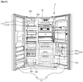
Fig. 1 is a view of a refrigerator with a door opened according to an embodiment. -
Fig. 2 is a partially perspective view illustrating an upper portion of a cabinet according to an embodiment. -
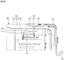
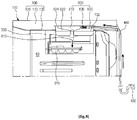
Fig. 3 is a partially schematic sectional view illustrating a structure of the upper portion of the cabinet. -
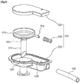
Fig. 4 is an exploded perspective view illustrating a structure of a water supply unit according to an embodiment. -
Fig. 5 is a view illustrating a flow state of water in the water supply unit. -
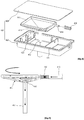
Fig. 6 is an exploded perspective view illustrating a structure of a water supply unit according to another embodiment. -
Fig. 7 is a view illustrating a flow state of water in the water supply unit. -
Fig. 8 is a sectional view illustrating a structure of an upper portion of a cabinet according to another embodiment. -
Fig. 9 is a view of a refrigerator with a door opened according to another embodiment. -
FIG. 10 is a side-sectional view of a refrigerator according to another embodiment. -
Fig. 11 is a view of a refrigerator with a door opened according to another embodiment. - For convenience of description, a side-by-side type refrigerator is described as an example in the embodiments. Also, in the refrigerator, a blowing device may be disposed inside a freezing compartment. However, the present disclosure is not limited thereto. All types of refrigerator whether or not including a blowing device may incorporate the invention.
- Referring to
Fig. 1 , arefrigerator 1 includes acabinet 100 defining a storage space and adoor 200 which is openable or closable on thecabinet 100. An outer appearance of the refrigerator may be defined by thecabinet 100 and thedoor 200. - The inside of the
cabinet 100 is partitioned into left and right sides by abarrier 110. A freezingcompartment 10 is defined at the left side of thecabinet 100, and arefrigerating compartment 20 is defined at the right side of thecabinet 100. A plurality of shelves and drawers are disposed inside the freezingcompartment 20 and therefrigerating compartment 10 to receive foods. - An
ice making apparatus 300 is disposed inside the freezingcompartment 10. Theice making apparatus 300 is configured to make and store an ice. Theice making apparatus 300 includes anice tray 310 in which ices are made and an ice bank disposed under theice tray 310 to store the made ices. - Each of the
ice tray 310 and theice bank 320 which constitute theice making apparatus 300 may have various shapes according to a shape of theice making apparatus 300. Theice making apparatus 300 may be disposed in a freezingcompartment door 210 except the freezingcompartment 10. As necessary, theice making apparatus 300 may be disposed inside an ice making chamber having an independent insulating space in therefrigerating compartment 20 or arefrigerating compartment door 220. - The
door 200 may include the freezingcompartment door 210 and the refrigeratingcompartment door 220 which respectively open or close therefrigerating compartment 20 and the freezingcompartment 10. The freezingcompartment door 210 and the refrigeratingcompartment door 220 are rotatably disposed on thecabinet 100 to open or close therefrigerating compartment 20 and the freezingcompartment 10. - A
home bar 222 disposed on the outside of the refrigeratingcompartment door 220 to define an openable receiving space may be disposed on therefrigerating compartment door 220. Also, a dispenser (not shown) may be disposed in the freezingcompartment door 210 to dispense purified water or ices made in theice making apparatus 300 to the outside. Anice chute 212 may be disposed on the freezingcompartment door 210 to allow theice making apparatus 300 to communicate with the dispenser in a state where the freezingcompartment door 210 is closed. -
Fig. 2 is a partially perspective view illustrating an upper portion of a cabinet according to an embodiment.Fig. 3 is a partially schematic sectional view illustrating a structure of the upper portion of the cabinet.Fig. 4 is an exploded perspective view illustrating a structure of a water supply unit according to an embodiment. - Referring to
Figs. 2 to 4 , thecabinet 100 has a hexahedral shape with a front surface opened. Also, thecabinet 100 includes anouter case 120 defining an outer appearance thereof and aninner case 130 coupled to theouter case 120 to define the storage space. Aninsulation material 140 is foamed and filled into a space between theouter case 120 and theinner case 130. - A
main control unit 150 is disposed on a top surface of thecabinet 100. Themain control unit 150 includes a main printed circuit board (PCB) for operating the refrigerator. Themain control unit 150 protrudes upward from the top surface of thecabinet 100. - Also, a
water supply unit 400 is disposed on the top surface of thecabinet 100. Thewater supply unit 400 may be disposed directly above theice making apparatus 300. Thus, thewater supply unit 400 is disposed on the top surface of thecabinet 100 at a side of the freezingcompartment 10. A water supplyunit mounting part 122 which is recessed downward may be defined in the top surface of thecabinet 100 corresponding to the mounted position of theice making apparatus 300 to mount thewater supply unit 400. - The
ice making apparatus 300 may include theice tray 310, theice bank 320, and aframe 330. Theframe 330 fixes theice tray 310 or theice tray 310 and theice bank 320. Theframe 330 is fixedly mounted on a top surface of the inside of the freezingcompartment 10. Theframe 330 is disposed on a position corresponding to that of the water supplyunit mounting part 122. Also, theice tray 310 may be easily accessible through theframe 330. - A
water supply passage 440 is connected to awater supply source 450 such as a water pipe disposed outside the refrigerator and is also connected to thewater supply unit 400. Here, a portion of thewater supply passage 440 is exposed to the outside, and the remaining portion of thewater supply passage 440 is buried into theinsulation material 140. A water tank disposed within the refrigerator may be used as thewater supply source 450. Thewater supply passage 440 may be disposed inside the refrigerator to connect thewater supply source 450 to thewater supply unit 400. - The
water supply unit 400 includes afill tank 410 into which water is supplied, a watersupply unit case 420 for receiving thefill tank 410, and atube connector 430 connecting thefill tank 410 to thewater supply unit 400. - The
fill tank 410 defines a space into which water supplied through thewater supply passage 440 is introduced. Thefill tank 410 has an inner sectional area greater than a sectional area of thewater supply passage 440. Thus, when water having a high pressure is introduced into thefill tank 410, the inside of thefill tank 410 is decreased in pressure. Thefill tank 410 may seal portions remaining except aguide tube 412 and aconnection tube 414. Also, thefill tank 410 has a predetermined volume. - The
guide tube 412 is disposed on a bottom surface of thefill tank 410 to extend downward so that water within thefill tank 410 is supplied into theice tray 310. Theguide tube 412 vertically extends downward toward theice tray 310. - The
guide tube 412 may be integrally formed when thefill tank 410 is formed. Theguide tube 412 may be mounted at a side of thefill tank 410. Theconnection tube 414 extends outward and is connected to thewater supply passage 440 through thetube connector 430. - The
fill tank 410 may have a rounded inner surface so that water introduced through theconnection tune 414 is moved while being rotated. Also, a bottom surface of thefill tank 410 may be inclined downward. In addition, the bottom surface of thefill tank 410 may be inclined toward awater discharge hole 416 corresponding to an upper end of theguide tube 412. - Thus, the high-pressure water introduced through the
connection tube 414 may be decreased in flow rate and pressure while being moved along an inner wall of thefill tank 410. Also, the water may be moved along the inclined bottom surface of thefill tank 410 and then discharged through thewater discharge hole 416. - The water
supply unit case 420 is mounted on the water supplyunit mounting part 122. The watersupply unit case 420 includes acase body 422 defining a space in which thefill tank 410 is received and acase cover 424 for opening or closing an opened top surface of the case body. - A fixing
part 426 on which thefill tank 410 is fixedly mounted is disposed inside thecase body 422. Thefill tank 410 may be maintained in a state in which it is fixed to the inside of the watersupply unit case 420 by the fixingpart 426. A space for receiving thetube connector 430 may be defined inside thecase body 422. Thus, thewater supply passage 440 and thefill tank 410 may be connected to each other inside the watersupply unit case 420 by thetube connector 430. - The
case cover 424 may open or close thecase body 422. In a state where thecase cover 424 is closed, thecase cover 424 may be flush with theouter case 120. - The
case body 422 may be assembled with theouter case 120 and then fixedly mounted. Also, thecase body 422 may contact a portion of theinsulation material 140 disposed inside the cabinet and then be fixedly mounted. - Hereinafter, a water supply process of the refrigerator according to an embodiment will be described in detail with reference to the accompanying drawings.
-
Fig. 5 is a view illustrating a flow state of water in the water supply unit. - Referring to
Figs. 3 to 5 , when a water supply signal for making an ice is transmitted, water is supplied through thewater supply passage 440 connected to thewater supply source 450. In case where a water pipe is used as thewater supply source 450, water is supplied up to thewater supply unit 400 by its water pressure. When a pump (not shown) is provided on thewater supply passage 440, water is supplied through thewater supply passage 440 by an operation of the pump. - The water supplied through the
water supply passage 440 connected to thewater supply unit 400 is supplied into thefill tank 410 through theconnection tube 414. Thefill tank 410 has an inner space greater than that of thewater supply passage 440. Thus, the inflowing water is decreased in flow rate and water pressure. - The water introduced into the
fill tank 410 is rotated along the inner surface of thefill tank 410 and moved downward along the bottom surface of thefill tank 410 inclined downward. Then, the water is introduced into theguide tube 412 through thewater discharge hole 416 defined in the bottom surface of thefill tank 410. - The water within the
fill tank 410 is supplied into theice making apparatus 300 through theguide tube 412. A lower end of theguide tube 412 may be disposed above theice tray 310, and water supplied from theguide tube 412 may be filled into theice tray 310 at a predetermined rate. - The water introduced into the
fill tank 410 is vertically moved downward through theguide tube 412 while being filled into thefill tank 410. Here, the water within thefill tank 410 drops down by a self-weight. If thefill tank 410 is not completely filled, the water is discharged at a pressure less than that of thewater supply passage 440. - Since the water dropping down through the
guide tube 412 is not affected by a pressure of the introduced water, the water may be supplied into theice tray 310 at a uniform pressure and flow rate always. Thus, it may prevent the water from being spattered or locally supplied. - In addition to the foregoing embodiment, a refrigerator according to various embodiments may be exemplified. Hereinafter, a refrigerator according to another embodiment will be described.
- In the refrigerator according to another embodiment, a fill tank being part of a water supply unit has a circular shape so that water smoothly flows inside the fill tank.
- Thus, according to another embodiment, the parts except for the water supply unit are the same as those of the foregoing embodiments, and thus descriptions thereof will be omitted. Also, like reference numeral denote like elements.
-
Fig. 6 is an exploded perspective view illustrating a structure of a water supply unit according to another embodiment.Fig. 7 is a view illustrating a flow state of water in the water supply unit. - Referring to
Figs. 6 and7 , a water supply unit 500 according to another embodiment includes afill tank 510 into which water is supplied from a water supply passage 540, a watersupply unit case 520 for receiving thefill tank 510, and atube connector 530 connecting the water supply passage 540 to thefill tank 510. - In detail, the
fill tank 510 has an expanded space relative to an inner space of the water supply passage 540. Thus, the water supplied through the water supply passage 540 is may reduced in pressure within thefill tank 510. - The
fill tank 510 has a circular sectional shape. Thus, when water is supplied through aconnection tube 514 disposed on a side of thefill tank 510, the water is moved along a wall of thefill tank 510. Here, since thefill tank 510 has the circular sectional shape, the water may be moved along the inner wall of thefill tank 510 by its inflow pressure. - The
fill tank 510 is inclined toward awater discharge hole 516 defined in a bottom surface thereof. Thus, the water introduced through theconnection tube 514 flows spirally along the inner surface of thefill tank 510 and then flows toward thewater discharge hole 516. The water inflowing into thewater discharge hole 516 is supplied into theice tray 310 through theguide tube 512 which extends downward. - The water
supply unit case 520 may include acase body 522 defining a space in which thefill tank 510 is received and acase cover 524 for opening or closing an opened top surface of the case body. The watersupply unit case 520 may include a filltank receiving part 526 having a shape corresponding to that of thefill tank 510 and a connector part on which thetube connector 530 is disposed and protruding from the filltank receiving part 526. Thus, the water supply passage 540 and thefill tank 514 may be connected to each other inside theconnector part 528 by thetube connector 530. - A refrigerator according to various other embodiments may be exemplified. Hereinafter, a refrigerator according to another embodiment will be described.
- In the refrigerator according to another embodiment, a water supply unit is mounted inside a storage space.
- Thus, according to another embodiment, the parts except for the water supply unit are the same as those of the foregoing embodiments, and thus descriptions thereof will be omitted. Also, like reference numeral denote like elements.
-
Fig. 8 is a sectional view illustrating a structure of an upper portion of a cabinet according to another embodiment. - Referring to
Fig. 8 , acabinet 100 according to another embodiment include anouter case 120, aninner case 130, and aninsulation material 140. A water supplyunit mounting part 132 which is recessed upward is defined in a top surface of the inside of theinner case 130. - A
water supply unit 600 includes afill tank 610 connected to thewater supply passage 440 to receive water, a watersupply unit case 620 for receiving thefill tank 610, and atube connector 630 connecting thewater supply passage 440 to thefill tank 610. - The water
supply unit case 620 may include a case body defining a space for receiving thefill tank 610 and acase cover 624 for covering an opened bottom surface of thecase body 622. Thecase body 622 is fixedly mounted on the water supplyunit mounting part 132. Thecase cover 624 may be openably disposed inside the storage space and exposed to a side of the inside of the refrigerator. In a state where thecase cover 624 is closed, thecase cover 624 may be flush with theinner case 130. - The
water supply unit 600 has the same inner structure as that of thewater supply unit 400 according to the foregoing embodiments except that it is mounted on theinner case 130. - The
water supply passage 440 passes through acabinet 100 from a rear side toward the inside of thecabinet 100. Also, thewater supply unit 440 is connected to thewater supply unit 600. Also, thewater supply passage 440 is buried within and fixed to aninsulation material 140. - Thus, water supplied through the
water supply passage 440 may be stably supplied into anice tray 310 inside a freezingcompartment 10 through aguide tube 612 after a pressure thereof is reduced inside thefill tank 610 of thewater supply unit 600. - A refrigerator according to various other embodiments may be exemplified. Hereinafter, a refrigerator according to another embodiment will be described.
- In the refrigerator according to another embodiment, an ice making apparatus and a water supply unit are disposed in a refrigerating compartment door.
-
Fig. 9 is a view of a refrigerator with a door opened according to another embodiment. - Referring to
Fig. 9 , arefrigerator 2 according to another embodiment includes acabinet 30 defining a storage space and a door for opening/closing the storage space. Here, an outer appearance of therefrigerator 2 is defined by thecabinet 30 and the door. - Also, the storage space inside the
cabinet 30 is vertically partitioned to define a refrigerating compartment 32 at an upper side and a freezing compartment 34 at a lower side. Thedoor 40 may include arefrigerating compartment door 42 for covering the refrigerating compartment 32 and a freezingcompartment door 44 for covering the freezing compartment 34. - The refrigerating
compartment door 42 is coupled to thecabinet 30 by ahinge 46. Thus, a pair of doors may be rotatably mounted on thecabinet 30. Anice making chamber 700 that is an independent insulation space may be defined in therefrigerating compartment door 42. Theice making chamber 700 provides a space in which ices are mode and stored. Cool air supplied from the freeing compartment 34 or an evaporator may be guided to theice making chamber 700 by a duct. - An
ice making apparatus 710 for making ices is disposed inside theice making chamber 700. Theice making apparatus 710 may include anice maker 712 for making ices and anice bank 714 for storing the made ices. - A
water supply unit 720 for supplying water into theice maker 712 is disposed above theice maker 712. Thewater supply unit 720 is connected to awater supply passage 440. Since thewater supply unit 720 has the same inner structure as that of thewater supply unit 400 according to the foregoing embodiments, their detailed description will be omitted. - The
water supply unit 720 may be disposed above theice making chamber 700. Also, at least one portion of thewater supply unit 720 may be buried into the refrigeratingcompartment door 42 or the insulation material of theice making chamber 700 to prevent the water from being frozen. Then, thewater supply passage 440 is guided to therefrigerating compartment door 42 through thehinge 46. Thus, thewater supply passage 440 is connected to thewater supply unit 720. - A refrigerator according to various other embodiments may be exemplified. Hereinafter, a refrigerator according to another embodiment will be described.
- In the refrigerator according to another embodiment, a water supply unit is mounted on a barrier.
-
FIG. 10 is a side-sectional view of a refrigerator according to another embodiment. - Referring to
Fig. 10 , a refrigerator 3 according to another embodiment includes acabinet 50 defining a storage space and a door 60 for opening/closing the storage space. Here, an outer appearance of therefrigerator 2 is defined by thecabinet 50 and the door 60. - Also, the storage space inside the
cabinet 50 is vertically partitioned by a barrier 52 to define arefrigerating compartment 54 at an upper side and a freezingcompartment 56 at a lower side. The door 60 may include a refrigerating compartment door 60 for covering therefrigerating compartment 54 and a freezing compartment door 60 for covering the freezingcompartment 56. - An
ice making apparatus 810 is disposed inside the freezingcompartment 56. Theice making apparatus 810 may be disposed under the barrier 52 or mounted on the barrier 52. Theice maker 810 may include theice tray 812 for making ices and a basket 814 for storing the ices made in theice tray 812. - A
water supply unit 820 may be disposed on the barrier 52 above theice making apparatus 810. Thewater supply unit 820 is connected to awater supply passage 440 to receive water for making ices from awater supply source 450. Thewater supply unit 820 has the same structure as that of thewater supply unit 400 according to the foregoing embodiments. - The
water supply unit 820 is seated upward on the barrier 5. Aguide tube 822 passes through the barrier 52 to vertically extend upward form theice tray 812, thereby supplying water for making ices. - The
water supply passage 440 connected to thewater supply unit 820 is guided inside the barrier 52 on a rear surface of thecabinet 50. Then, thewater supply passage 440 may be guided along the inside of the barrier 52 and connected to thewater supply unit 820. - As necessary, the
water supply unit 820 may be disposed under the freezingcompartment 56 and fixedly mounted on a bottom surface of the barrier 52. - A refrigerator according to various other embodiments may be exemplified. Hereinafter, a refrigerator according to another embodiment will be described.
- In the refrigerator according to another embodiment, water within a detachable water tank is supplied into an ice making apparatus through a water supply unit.
-
Fig. 11 is a view of a refrigerator with a door opened according to another embodiment. - Referring to
Fig. 11 , a refrigerator 4 according to another embodiment includes a cabinet partitioned into left and right sides to define a freezingcompartment 72 and arefrigerating compartment 74 and a door including a freezingcompartment door 82 and arefrigerating compartment door 84 which respectively cover the freezingcompartment 72 and the freezingcompartment 74. - An
ice making apparatus 910 for making ices is disposed at an upper side of the freezingcompartment 72. Theice making apparatus 910 may include anice tray 912 for making ices and an ice bank 914 for storing the made ices. The ices stored in the ice bank 914 may be dispensed to the outside through a dispenser (not shown) of the freezingcompartment door 82. - A
water supply unit 920 is disposed above theice making apparatus 910. Thewater supply unit 920 is mounted on an outer upper side of thecabinet 70. Thewater supply unit 920 may supply water into theice making apparatus 910 through aguide tube 922 passing through thecabinet 70. Also, thewater supply unit 920 is connected to awater supply passage 930 connected to a water supply source 940. - The water supply source 940 constituted as a detachable water tank is disposed on the
refrigerating compartment door 84. The water supply source 940 may be aplastic bottle 942. Alternatively, the water supply source 940 may be a water tank 944 which is detachably designed. The water supply source 940 may be disposed inside the refrigeratingcompartment 74, but therefrigerating compartment door 84. - The
water supply passage 930 is disposed via the outside of thecabinet 70. As necessary, thewater supply passage 930 may be disposed inside thecabinet 70. Apump 932 and avalve 934 for stably supplying water into thewater supply passage 930 may be disposed on thewater supply passage 930. - According to the embodiments, the water supplied from the water supply source is supplied into the water supply unit through the water supply unit. The water introduced into the water supply unit is supplied into the ice making apparatus in a state where the pressure and flow rate of the water are adjusted while flowing inside the water supply unit.
- Thus, it may prevent the water supplied into the ice making apparatus from being spattered or overflowing due to a high pressure. In addition, it may prevent the stored ices from being tangled with each other or deteriorated when the ices are made.
- Also, since the water supply unit is disposed vertically above the ice making apparatus to supply the water, the water spattering phenomenon may be minimized to further stably supply the water at the more stable position.
- Although embodiments have been described with reference to a number of illustrative embodiments thereof, it should be understood that numerous other modifications and embodiments can be devised by those skilled in the art that will fall within the scope of the claims. More particularly, various variations and modifications are possible in the component parts and/or arrangements of the subject combination arrangement within the scope of the appended claims.
Claims (13)
- A refrigerator (1) with an ice making apparatus (300) which uses water supplied from a water supply source to make ice, the refrigerator comprising:a cabinet (100) defining a storage space which is opened or closed by a door (200);a water supply passage (440) extending from the water supply source (450) toward the ice making apparatus; anda water supply unit (400) disposed above the ice making apparatus, the water supply unit having a sectional area greater than that of the water supply passage and being connected to the water supply passage to receive water supplied through the water supply passage,wherein the water supply unit comprises:a case (520) mounted on the cabinet;a fill tank (510) disposed inside the case, the fill tank providing an expanded space relative to a space within the water supply passage to receive the supplied water; anda guide tube (512) disposed in the fill tank to extend toward the inside of the refrigerator, thereby guiding water to the ice making apparatus;the refrigerator being characterised by:
a connection tube (514) disposed on a side wall of the fill tank, configured such that the water introduced therethrough flows spirally along an inner surface of the fill tank and then flows towards the guide tube. - The refrigerator according to claim 1, wherein the water supply unit is mounted on an outer top surface of the cabinet.
- The refrigerator according to claim 2, wherein the water supply unit is mounted so that a top surface thereof is exposed to an outer case (120) defining an outer appearance of the cabinet.
- The refrigerator according to claim 2, wherein the water supply unit is buried into an insulation material filled into the cabinet.
- The refrigerator according to claim 2, wherein the water supply unit is exposed to the outside of the refrigerator through the top surface of the cabinet.
- The refrigerator according to claim 1, wherein the water supply unit is mounted inside the storage space.
- The refrigerator according to claim 1, wherein the water supply unit is disposed on the door for opening or closing the storage space.
- The refrigerator according to claim 1, wherein the water supply unit is disposed on a barrier (52) for partitioning the storage space.
- The refrigerator according to claim 1, wherein the water supply source is at least one of a water pipe disposed outside the refrigerator or a water tank detachably disposed inside the refrigerator.
- The refrigerator according to claim 1, wherein a flow direction of water supplied into the water supply unit crosses that of water supplied outside the water supply unit.
- The refrigerator according to claim 1, wherein the case comprises:a case body (522) disposed on the cabinet, the case body receiving the fill tank; anda case cover (524) opening or closing an opened surface of the case body, the case cover being exposed to the outside of the refrigerator.
- The refrigerator according to claim 1, wherein at least one portion of an inner surface of the water supply unit is curved so that the supplied water is supplied into the ice making apparatus while being rotated along the inner surface of the water supply unit.
- The refrigerator according to claim 1, wherein at least one portion of an inner surface of the water supply unit is inclined so that the supplied water is supplied into the ice making apparatus while being moved along the inclined inside surface of the water supply unit.
Applications Claiming Priority (1)
| Application Number | Priority Date | Filing Date | Title |
|---|---|---|---|
| KR1020100067828A KR101713327B1 (en) | 2010-07-14 | 2010-07-14 | Refirgerator |
Publications (3)
| Publication Number | Publication Date |
|---|---|
| EP2407737A2 EP2407737A2 (en) | 2012-01-18 |
| EP2407737A3 EP2407737A3 (en) | 2018-01-24 |
| EP2407737B1 true EP2407737B1 (en) | 2020-09-02 |
Family
ID=44582199
Family Applications (1)
| Application Number | Title | Priority Date | Filing Date |
|---|---|---|---|
| EP11173607.0A Not-in-force EP2407737B1 (en) | 2010-07-14 | 2011-07-12 | Refrigerator |
Country Status (4)
| Country | Link |
|---|---|
| US (1) | US8800315B2 (en) |
| EP (1) | EP2407737B1 (en) |
| KR (1) | KR101713327B1 (en) |
| CN (1) | CN102338533B (en) |
Families Citing this family (17)
| Publication number | Priority date | Publication date | Assignee | Title |
|---|---|---|---|---|
| CN103162502B (en) * | 2011-12-16 | 2017-02-15 | 博西华电器(江苏)有限公司 | Refrigeration device |
| CN102927764B (en) * | 2012-11-26 | 2015-02-25 | 合肥美的电冰箱有限公司 | Water tank for refrigerator and refrigerator |
| US20150201723A1 (en) * | 2013-02-01 | 2015-07-23 | Treefrog Developments, Inc. | Encasements for an electronic device having a biometric scanner |
| CN105352240A (en) * | 2015-12-14 | 2016-02-24 | 合肥华凌股份有限公司 | Ice making component and refrigerator |
| CN105650955B (en) * | 2015-12-31 | 2018-03-30 | 海信容声(广东)冰箱有限公司 | A kind of water guide funnel and ice maker |
| US10627147B2 (en) | 2016-04-21 | 2020-04-21 | Electrolux Home Products, Inc. | Fill section heater for a refrigeration appliance |
| KR102345097B1 (en) * | 2016-11-29 | 2021-12-31 | 엘지전자 주식회사 | Refrigerator |
| US10252198B2 (en) * | 2017-03-02 | 2019-04-09 | Bsh Hausgeraete Gmbh | Filter device for a beverage and/or ice dispenser unit of a household cooling appliance and household appliance having a filter device |
| CN112050510B (en) * | 2019-06-06 | 2022-03-25 | 青岛海尔电冰箱有限公司 | Ice making assembly and refrigerator having the same |
| CN112050509A (en) * | 2019-06-06 | 2020-12-08 | 青岛海尔电冰箱有限公司 | Ice making assembly and refrigerator having the same |
| PL3875875T3 (en) * | 2019-07-04 | 2024-04-29 | Arçelik Anonim Sirketi | A cooling appliance having an icemaker |
| CN110779259A (en) * | 2019-11-05 | 2020-02-11 | 青岛海尔电冰箱有限公司 | refrigerator |
| CN111288720B (en) * | 2020-03-02 | 2022-03-29 | 海信(山东)冰箱有限公司 | Refrigerator with ice maker |
| CN218645839U (en) * | 2022-02-25 | 2023-03-17 | 青岛海尔电冰箱有限公司 | Liquid storage device and refrigerator with same |
| CN116697672A (en) * | 2022-02-25 | 2023-09-05 | 青岛海尔电冰箱有限公司 | Refrigerator with a refrigerator body |
| CN115875921B (en) * | 2022-12-29 | 2025-12-19 | Tcl家用电器(合肥)有限公司 | Refrigerator with a refrigerator body |
| CN119998609A (en) * | 2023-01-13 | 2025-05-13 | 三星电子株式会社 | refrigerator |
Family Cites Families (20)
| Publication number | Priority date | Publication date | Assignee | Title |
|---|---|---|---|---|
| JPH0826664B2 (en) * | 1989-06-02 | 1996-03-13 | 学校法人早稲田大学 | Pillar assembly method using a robot |
| JPH0776659B2 (en) * | 1989-10-24 | 1995-08-16 | 株式会社東芝 | refrigerator |
| JP2735170B2 (en) * | 1993-09-07 | 1998-04-02 | 松下冷機株式会社 | Freezer refrigerator ice making equipment |
| TW330978B (en) * | 1995-03-31 | 1998-05-01 | Mitsubishi Electric Corp | Automatic ice-making device and refrigerator the invention relates to an automatic ice-making device comprising a water supply tank, an ice-making plate and a water-supply pump. |
| JP3434943B2 (en) | 1995-10-06 | 2003-08-11 | 株式会社日立製作所 | refrigerator |
| JP3744043B2 (en) * | 1996-01-09 | 2006-02-08 | 株式会社日立製作所 | Refrigerator with automatic ice machine |
| KR100197906B1 (en) * | 1996-10-21 | 1999-06-15 | 전주범 | Automatic ice maker water dispenser in refrigerator |
| KR100276739B1 (en) * | 1998-10-31 | 2001-02-01 | 전주범 | Water supply device for automatic ice maker |
| JP3541147B2 (en) | 1999-08-03 | 2004-07-07 | 株式会社東芝 | Water supply equipment for ice making equipment |
| US6574982B1 (en) * | 2001-11-30 | 2003-06-10 | General Electric Company | Icemaker fill tube assembly |
| JP4172247B2 (en) | 2002-01-08 | 2008-10-29 | 三菱電機株式会社 | refrigerator |
| CN2543002Y (en) | 2002-03-25 | 2003-04-02 | 海尔集团公司 | Electric refrigerator |
| US7484382B2 (en) * | 2003-03-28 | 2009-02-03 | Lg Electronics Inc. | Refrigerator |
| JP4004479B2 (en) * | 2004-03-11 | 2007-11-07 | 三洋電機株式会社 | Refrigerator with automatic ice machine |
| US7337620B2 (en) * | 2005-05-18 | 2008-03-04 | Whirlpool Corporation | Insulated ice compartment for bottom mount refrigerator |
| KR20070075670A (en) * | 2006-01-14 | 2007-07-24 | 삼성전자주식회사 | Refrigerator and its control method |
| GB2454378B (en) * | 2006-08-15 | 2011-10-19 | Lg Electronics Inc | Ice tray assembly and refrigerator having same |
| EP2052196B1 (en) * | 2006-08-17 | 2018-12-26 | LG Electronics Inc. | Ice-making assembly and refrigerator using the same |
| KR101334576B1 (en) * | 2006-09-15 | 2013-11-28 | 엘지전자 주식회사 | Refrigerator ice maker |
| KR101548263B1 (en) * | 2008-10-02 | 2015-08-28 | 삼성전자 주식회사 | Refrigerator |
-
2010
- 2010-07-14 KR KR1020100067828A patent/KR101713327B1/en not_active Expired - Fee Related
-
2011
- 2011-07-12 EP EP11173607.0A patent/EP2407737B1/en not_active Not-in-force
- 2011-07-13 US US13/181,553 patent/US8800315B2/en active Active
- 2011-07-14 CN CN201110232819.7A patent/CN102338533B/en not_active Expired - Fee Related
Non-Patent Citations (1)
| Title |
|---|
| None * |
Also Published As
| Publication number | Publication date |
|---|---|
| US20120011877A1 (en) | 2012-01-19 |
| KR101713327B1 (en) | 2017-03-08 |
| EP2407737A2 (en) | 2012-01-18 |
| KR20120007202A (en) | 2012-01-20 |
| EP2407737A3 (en) | 2018-01-24 |
| CN102338533A (en) | 2012-02-01 |
| US8800315B2 (en) | 2014-08-12 |
| CN102338533B (en) | 2015-04-22 |
Similar Documents
| Publication | Publication Date | Title |
|---|---|---|
| US8800315B2 (en) | Refrigerator | |
| US8042353B2 (en) | Refrigerator door having a splash guide | |
| EP2568235B1 (en) | Refrigerator | |
| KR101997259B1 (en) | Refrigerator | |
| CN102235797B (en) | Refrigerator having a drawer | |
| EP2455691B1 (en) | Refrigerator | |
| KR101718995B1 (en) | Refrigerator | |
| CA2674507C (en) | Ice making and water delivery apparatus | |
| EP2519792B1 (en) | Refrigerator and control method thereof | |
| KR101631089B1 (en) | Ice maker and refrigerator having the same | |
| US20120111049A1 (en) | Refrigerator | |
| KR101830513B1 (en) | Refrigerator and method for controlling the same | |
| KR101512123B1 (en) | Refrigerator | |
| KR20190103807A (en) | Refrigerator and control method thereof | |
| KR20100027955A (en) | Refrigerator | |
| KR20170096326A (en) | A refrigerator | |
| EP4220052A1 (en) | Refrigerator | |
| KR101079469B1 (en) | Refrigerator | |
| US20260126242A1 (en) | Refrigerator | |
| KR101132481B1 (en) | An ice dispenser for refrigerator | |
| KR20240051625A (en) | Refrigerator | |
| KR20170026425A (en) | Refirgerator | |
| JP2008032368A (en) | refrigerator |
Legal Events
| Date | Code | Title | Description |
|---|---|---|---|
| 17P | Request for examination filed |
Effective date: 20110712 |
|
| AK | Designated contracting states |
Kind code of ref document: A2 Designated state(s): AL AT BE BG CH CY CZ DE DK EE ES FI FR GB GR HR HU IE IS IT LI LT LU LV MC MK MT NL NO PL PT RO RS SE SI SK SM TR |
|
| AX | Request for extension of the european patent |
Extension state: BA ME |
|
| PUAI | Public reference made under article 153(3) epc to a published international application that has entered the european phase |
Free format text: ORIGINAL CODE: 0009012 |
|
| RAP1 | Party data changed (applicant data changed or rights of an application transferred) |
Owner name: LG ELECTRONICS INC. |
|
| PUAL | Search report despatched |
Free format text: ORIGINAL CODE: 0009013 |
|
| AK | Designated contracting states |
Kind code of ref document: A3 Designated state(s): AL AT BE BG CH CY CZ DE DK EE ES FI FR GB GR HR HU IE IS IT LI LT LU LV MC MK MT NL NO PL PT RO RS SE SI SK SM TR |
|
| AX | Request for extension of the european patent |
Extension state: BA ME |
|
| RIC1 | Information provided on ipc code assigned before grant |
Ipc: F25D 23/12 20060101ALN20171219BHEP Ipc: F25C 1/04 20180101AFI20171219BHEP |
|
| GRAP | Despatch of communication of intention to grant a patent |
Free format text: ORIGINAL CODE: EPIDOSNIGR1 |
|
| STAA | Information on the status of an ep patent application or granted ep patent |
Free format text: STATUS: GRANT OF PATENT IS INTENDED |
|
| RIC1 | Information provided on ipc code assigned before grant |
Ipc: F25C 1/04 20180101AFI20200210BHEP Ipc: F25D 23/12 20060101ALN20200210BHEP |
|
| INTG | Intention to grant announced |
Effective date: 20200313 |
|
| GRAS | Grant fee paid |
Free format text: ORIGINAL CODE: EPIDOSNIGR3 |
|
| GRAA | (expected) grant |
Free format text: ORIGINAL CODE: 0009210 |
|
| STAA | Information on the status of an ep patent application or granted ep patent |
Free format text: STATUS: THE PATENT HAS BEEN GRANTED |
|
| AK | Designated contracting states |
Kind code of ref document: B1 Designated state(s): AL AT BE BG CH CY CZ DE DK EE ES FI FR GB GR HR HU IE IS IT LI LT LU LV MC MK MT NL NO PL PT RO RS SE SI SK SM TR |
|
| REG | Reference to a national code |
Ref country code: GB Ref legal event code: FG4D |
|
| REG | Reference to a national code |
Ref country code: AT Ref legal event code: REF Ref document number: 1309306 Country of ref document: AT Kind code of ref document: T Effective date: 20200915 Ref country code: CH Ref legal event code: EP |
|
| REG | Reference to a national code |
Ref country code: DE Ref legal event code: R096 Ref document number: 602011068426 Country of ref document: DE |
|
| REG | Reference to a national code |
Ref country code: IE Ref legal event code: FG4D |
|
| REG | Reference to a national code |
Ref country code: LT Ref legal event code: MG4D |
|
| PG25 | Lapsed in a contracting state [announced via postgrant information from national office to epo] |
Ref country code: HR Free format text: LAPSE BECAUSE OF FAILURE TO SUBMIT A TRANSLATION OF THE DESCRIPTION OR TO PAY THE FEE WITHIN THE PRESCRIBED TIME-LIMIT Effective date: 20200902 Ref country code: SE Free format text: LAPSE BECAUSE OF FAILURE TO SUBMIT A TRANSLATION OF THE DESCRIPTION OR TO PAY THE FEE WITHIN THE PRESCRIBED TIME-LIMIT Effective date: 20200902 Ref country code: GR Free format text: LAPSE BECAUSE OF FAILURE TO SUBMIT A TRANSLATION OF THE DESCRIPTION OR TO PAY THE FEE WITHIN THE PRESCRIBED TIME-LIMIT Effective date: 20201203 Ref country code: FI Free format text: LAPSE BECAUSE OF FAILURE TO SUBMIT A TRANSLATION OF THE DESCRIPTION OR TO PAY THE FEE WITHIN THE PRESCRIBED TIME-LIMIT Effective date: 20200902 Ref country code: NO Free format text: LAPSE BECAUSE OF FAILURE TO SUBMIT A TRANSLATION OF THE DESCRIPTION OR TO PAY THE FEE WITHIN THE PRESCRIBED TIME-LIMIT Effective date: 20201202 Ref country code: BG Free format text: LAPSE BECAUSE OF FAILURE TO SUBMIT A TRANSLATION OF THE DESCRIPTION OR TO PAY THE FEE WITHIN THE PRESCRIBED TIME-LIMIT Effective date: 20201202 Ref country code: LT Free format text: LAPSE BECAUSE OF FAILURE TO SUBMIT A TRANSLATION OF THE DESCRIPTION OR TO PAY THE FEE WITHIN THE PRESCRIBED TIME-LIMIT Effective date: 20200902 |
|
| REG | Reference to a national code |
Ref country code: NL Ref legal event code: MP Effective date: 20200902 |
|
| REG | Reference to a national code |
Ref country code: AT Ref legal event code: MK05 Ref document number: 1309306 Country of ref document: AT Kind code of ref document: T Effective date: 20200902 |
|
| PG25 | Lapsed in a contracting state [announced via postgrant information from national office to epo] |
Ref country code: PL Free format text: LAPSE BECAUSE OF FAILURE TO SUBMIT A TRANSLATION OF THE DESCRIPTION OR TO PAY THE FEE WITHIN THE PRESCRIBED TIME-LIMIT Effective date: 20200902 Ref country code: LV Free format text: LAPSE BECAUSE OF FAILURE TO SUBMIT A TRANSLATION OF THE DESCRIPTION OR TO PAY THE FEE WITHIN THE PRESCRIBED TIME-LIMIT Effective date: 20200902 Ref country code: RS Free format text: LAPSE BECAUSE OF FAILURE TO SUBMIT A TRANSLATION OF THE DESCRIPTION OR TO PAY THE FEE WITHIN THE PRESCRIBED TIME-LIMIT Effective date: 20200902 |
|
| PG25 | Lapsed in a contracting state [announced via postgrant information from national office to epo] |
Ref country code: SM Free format text: LAPSE BECAUSE OF FAILURE TO SUBMIT A TRANSLATION OF THE DESCRIPTION OR TO PAY THE FEE WITHIN THE PRESCRIBED TIME-LIMIT Effective date: 20200902 Ref country code: RO Free format text: LAPSE BECAUSE OF FAILURE TO SUBMIT A TRANSLATION OF THE DESCRIPTION OR TO PAY THE FEE WITHIN THE PRESCRIBED TIME-LIMIT Effective date: 20200902 Ref country code: NL Free format text: LAPSE BECAUSE OF FAILURE TO SUBMIT A TRANSLATION OF THE DESCRIPTION OR TO PAY THE FEE WITHIN THE PRESCRIBED TIME-LIMIT Effective date: 20200902 Ref country code: PT Free format text: LAPSE BECAUSE OF FAILURE TO SUBMIT A TRANSLATION OF THE DESCRIPTION OR TO PAY THE FEE WITHIN THE PRESCRIBED TIME-LIMIT Effective date: 20210104 Ref country code: CZ Free format text: LAPSE BECAUSE OF FAILURE TO SUBMIT A TRANSLATION OF THE DESCRIPTION OR TO PAY THE FEE WITHIN THE PRESCRIBED TIME-LIMIT Effective date: 20200902 Ref country code: EE Free format text: LAPSE BECAUSE OF FAILURE TO SUBMIT A TRANSLATION OF THE DESCRIPTION OR TO PAY THE FEE WITHIN THE PRESCRIBED TIME-LIMIT Effective date: 20200902 |
|
| PG25 | Lapsed in a contracting state [announced via postgrant information from national office to epo] |
Ref country code: ES Free format text: LAPSE BECAUSE OF FAILURE TO SUBMIT A TRANSLATION OF THE DESCRIPTION OR TO PAY THE FEE WITHIN THE PRESCRIBED TIME-LIMIT Effective date: 20200902 Ref country code: IS Free format text: LAPSE BECAUSE OF FAILURE TO SUBMIT A TRANSLATION OF THE DESCRIPTION OR TO PAY THE FEE WITHIN THE PRESCRIBED TIME-LIMIT Effective date: 20210102 Ref country code: AL Free format text: LAPSE BECAUSE OF FAILURE TO SUBMIT A TRANSLATION OF THE DESCRIPTION OR TO PAY THE FEE WITHIN THE PRESCRIBED TIME-LIMIT Effective date: 20200902 Ref country code: AT Free format text: LAPSE BECAUSE OF FAILURE TO SUBMIT A TRANSLATION OF THE DESCRIPTION OR TO PAY THE FEE WITHIN THE PRESCRIBED TIME-LIMIT Effective date: 20200902 |
|
| REG | Reference to a national code |
Ref country code: DE Ref legal event code: R097 Ref document number: 602011068426 Country of ref document: DE |
|
| PG25 | Lapsed in a contracting state [announced via postgrant information from national office to epo] |
Ref country code: SK Free format text: LAPSE BECAUSE OF FAILURE TO SUBMIT A TRANSLATION OF THE DESCRIPTION OR TO PAY THE FEE WITHIN THE PRESCRIBED TIME-LIMIT Effective date: 20200902 |
|
| PLBE | No opposition filed within time limit |
Free format text: ORIGINAL CODE: 0009261 |
|
| STAA | Information on the status of an ep patent application or granted ep patent |
Free format text: STATUS: NO OPPOSITION FILED WITHIN TIME LIMIT |
|
| 26N | No opposition filed |
Effective date: 20210603 |
|
| PG25 | Lapsed in a contracting state [announced via postgrant information from national office to epo] |
Ref country code: DK Free format text: LAPSE BECAUSE OF FAILURE TO SUBMIT A TRANSLATION OF THE DESCRIPTION OR TO PAY THE FEE WITHIN THE PRESCRIBED TIME-LIMIT Effective date: 20200902 Ref country code: SI Free format text: LAPSE BECAUSE OF FAILURE TO SUBMIT A TRANSLATION OF THE DESCRIPTION OR TO PAY THE FEE WITHIN THE PRESCRIBED TIME-LIMIT Effective date: 20200902 |
|
| PG25 | Lapsed in a contracting state [announced via postgrant information from national office to epo] |
Ref country code: IT Free format text: LAPSE BECAUSE OF FAILURE TO SUBMIT A TRANSLATION OF THE DESCRIPTION OR TO PAY THE FEE WITHIN THE PRESCRIBED TIME-LIMIT Effective date: 20200902 |
|
| REG | Reference to a national code |
Ref country code: CH Ref legal event code: PL |
|
| GBPC | Gb: european patent ceased through non-payment of renewal fee |
Effective date: 20210712 |
|
| PG25 | Lapsed in a contracting state [announced via postgrant information from national office to epo] |
Ref country code: MC Free format text: LAPSE BECAUSE OF FAILURE TO SUBMIT A TRANSLATION OF THE DESCRIPTION OR TO PAY THE FEE WITHIN THE PRESCRIBED TIME-LIMIT Effective date: 20200902 |
|
| REG | Reference to a national code |
Ref country code: BE Ref legal event code: MM Effective date: 20210731 |
|
| PG25 | Lapsed in a contracting state [announced via postgrant information from national office to epo] |
Ref country code: LI Free format text: LAPSE BECAUSE OF NON-PAYMENT OF DUE FEES Effective date: 20210731 Ref country code: GB Free format text: LAPSE BECAUSE OF NON-PAYMENT OF DUE FEES Effective date: 20210712 Ref country code: CH Free format text: LAPSE BECAUSE OF NON-PAYMENT OF DUE FEES Effective date: 20210731 |
|
| PG25 | Lapsed in a contracting state [announced via postgrant information from national office to epo] |
Ref country code: LU Free format text: LAPSE BECAUSE OF NON-PAYMENT OF DUE FEES Effective date: 20210712 Ref country code: FR Free format text: LAPSE BECAUSE OF NON-PAYMENT OF DUE FEES Effective date: 20210731 |
|
| PG25 | Lapsed in a contracting state [announced via postgrant information from national office to epo] |
Ref country code: IE Free format text: LAPSE BECAUSE OF NON-PAYMENT OF DUE FEES Effective date: 20210712 Ref country code: BE Free format text: LAPSE BECAUSE OF NON-PAYMENT OF DUE FEES Effective date: 20210731 |
|
| PG25 | Lapsed in a contracting state [announced via postgrant information from national office to epo] |
Ref country code: HU Free format text: LAPSE BECAUSE OF FAILURE TO SUBMIT A TRANSLATION OF THE DESCRIPTION OR TO PAY THE FEE WITHIN THE PRESCRIBED TIME-LIMIT; INVALID AB INITIO Effective date: 20110712 Ref country code: CY Free format text: LAPSE BECAUSE OF FAILURE TO SUBMIT A TRANSLATION OF THE DESCRIPTION OR TO PAY THE FEE WITHIN THE PRESCRIBED TIME-LIMIT Effective date: 20200902 |
|
| PG25 | Lapsed in a contracting state [announced via postgrant information from national office to epo] |
Ref country code: MK Free format text: LAPSE BECAUSE OF FAILURE TO SUBMIT A TRANSLATION OF THE DESCRIPTION OR TO PAY THE FEE WITHIN THE PRESCRIBED TIME-LIMIT Effective date: 20200902 |
|
| PG25 | Lapsed in a contracting state [announced via postgrant information from national office to epo] |
Ref country code: MT Free format text: LAPSE BECAUSE OF FAILURE TO SUBMIT A TRANSLATION OF THE DESCRIPTION OR TO PAY THE FEE WITHIN THE PRESCRIBED TIME-LIMIT Effective date: 20200902 |
|
| PGFP | Annual fee paid to national office [announced via postgrant information from national office to epo] |
Ref country code: DE Payment date: 20240604 Year of fee payment: 14 |
|
| PG25 | Lapsed in a contracting state [announced via postgrant information from national office to epo] |
Ref country code: TR Free format text: LAPSE BECAUSE OF FAILURE TO SUBMIT A TRANSLATION OF THE DESCRIPTION OR TO PAY THE FEE WITHIN THE PRESCRIBED TIME-LIMIT Effective date: 20200902 |
|
| REG | Reference to a national code |
Ref country code: DE Ref legal event code: R119 Ref document number: 602011068426 Country of ref document: DE |
|
| PG25 | Lapsed in a contracting state [announced via postgrant information from national office to epo] |
Ref country code: DE Free format text: LAPSE BECAUSE OF NON-PAYMENT OF DUE FEES Effective date: 20260203 |